CN103068342A - Expandable implant - Google Patents
Expandable implantDownload PDFInfo
- Publication number
- CN103068342A CN103068342ACN2010800685263ACN201080068526ACN103068342ACN 103068342 ACN103068342 ACN 103068342ACN 2010800685263 ACN2010800685263 ACN 2010800685263ACN 201080068526 ACN201080068526 ACN 201080068526ACN 103068342 ACN103068342 ACN 103068342A
- Authority
- CN
- China
- Prior art keywords
- implant
- chamber
- implant body
- expansion
- implant according
- Prior art date
- Legal status (The legal status is an assumption and is not a legal conclusion. Google has not performed a legal analysis and makes no representation as to the accuracy of the status listed.)
- Granted
Links
Images


Classifications
- A—HUMAN NECESSITIES
- A61—MEDICAL OR VETERINARY SCIENCE; HYGIENE
- A61B—DIAGNOSIS; SURGERY; IDENTIFICATION
- A61B17/00—Surgical instruments, devices or methods
- A61B17/56—Surgical instruments or methods for treatment of bones or joints; Devices specially adapted therefor
- A61B17/58—Surgical instruments or methods for treatment of bones or joints; Devices specially adapted therefor for osteosynthesis, e.g. bone plates, screws or setting implements
- A61B17/68—Internal fixation devices, including fasteners and spinal fixators, even if a part thereof projects from the skin
- A61B17/686—Plugs, i.e. elements forming interface between bone hole and implant or fastener, e.g. screw
- A—HUMAN NECESSITIES
- A61—MEDICAL OR VETERINARY SCIENCE; HYGIENE
- A61B—DIAGNOSIS; SURGERY; IDENTIFICATION
- A61B17/00—Surgical instruments, devices or methods
- A61B17/56—Surgical instruments or methods for treatment of bones or joints; Devices specially adapted therefor
- A61B17/58—Surgical instruments or methods for treatment of bones or joints; Devices specially adapted therefor for osteosynthesis, e.g. bone plates, screws or setting implements
- A61B17/68—Internal fixation devices, including fasteners and spinal fixators, even if a part thereof projects from the skin
- A61B17/70—Spinal positioners or stabilisers, e.g. stabilisers comprising fluid filler in an implant
- A—HUMAN NECESSITIES
- A61—MEDICAL OR VETERINARY SCIENCE; HYGIENE
- A61B—DIAGNOSIS; SURGERY; IDENTIFICATION
- A61B17/00—Surgical instruments, devices or methods
- A61B17/56—Surgical instruments or methods for treatment of bones or joints; Devices specially adapted therefor
- A61B17/58—Surgical instruments or methods for treatment of bones or joints; Devices specially adapted therefor for osteosynthesis, e.g. bone plates, screws or setting implements
- A61B17/68—Internal fixation devices, including fasteners and spinal fixators, even if a part thereof projects from the skin
- A61B17/80—Cortical plates, i.e. bone plates; Instruments for holding or positioning cortical plates, or for compressing bones attached to cortical plates
- A61B17/809—Cortical plates, i.e. bone plates; Instruments for holding or positioning cortical plates, or for compressing bones attached to cortical plates with bone-penetrating elements, e.g. blades or prongs
- A—HUMAN NECESSITIES
- A61—MEDICAL OR VETERINARY SCIENCE; HYGIENE
- A61B—DIAGNOSIS; SURGERY; IDENTIFICATION
- A61B17/00—Surgical instruments, devices or methods
- A61B17/56—Surgical instruments or methods for treatment of bones or joints; Devices specially adapted therefor
- A61B17/58—Surgical instruments or methods for treatment of bones or joints; Devices specially adapted therefor for osteosynthesis, e.g. bone plates, screws or setting implements
- A61B17/88—Osteosynthesis instruments; Methods or means for implanting or extracting internal or external fixation devices
- A61B17/885—Tools for expanding or compacting bones or discs or cavities therein
- A61B17/8852—Tools for expanding or compacting bones or discs or cavities therein capable of being assembled or enlarged, or changing shape, inside the bone or disc
- A61B17/8855—Tools for expanding or compacting bones or discs or cavities therein capable of being assembled or enlarged, or changing shape, inside the bone or disc inflatable, e.g. kyphoplasty balloons
- A—HUMAN NECESSITIES
- A61—MEDICAL OR VETERINARY SCIENCE; HYGIENE
- A61F—FILTERS IMPLANTABLE INTO BLOOD VESSELS; PROSTHESES; DEVICES PROVIDING PATENCY TO, OR PREVENTING COLLAPSING OF, TUBULAR STRUCTURES OF THE BODY, e.g. STENTS; ORTHOPAEDIC, NURSING OR CONTRACEPTIVE DEVICES; FOMENTATION; TREATMENT OR PROTECTION OF EYES OR EARS; BANDAGES, DRESSINGS OR ABSORBENT PADS; FIRST-AID KITS
- A61F2/00—Filters implantable into blood vessels; Prostheses, i.e. artificial substitutes or replacements for parts of the body; Appliances for connecting them with the body; Devices providing patency to, or preventing collapsing of, tubular structures of the body, e.g. stents
- A61F2/02—Prostheses implantable into the body
- A61F2/30—Joints
- A61F2/30767—Special external or bone-contacting surface, e.g. coating for improving bone ingrowth
- A—HUMAN NECESSITIES
- A61—MEDICAL OR VETERINARY SCIENCE; HYGIENE
- A61F—FILTERS IMPLANTABLE INTO BLOOD VESSELS; PROSTHESES; DEVICES PROVIDING PATENCY TO, OR PREVENTING COLLAPSING OF, TUBULAR STRUCTURES OF THE BODY, e.g. STENTS; ORTHOPAEDIC, NURSING OR CONTRACEPTIVE DEVICES; FOMENTATION; TREATMENT OR PROTECTION OF EYES OR EARS; BANDAGES, DRESSINGS OR ABSORBENT PADS; FIRST-AID KITS
- A61F2/00—Filters implantable into blood vessels; Prostheses, i.e. artificial substitutes or replacements for parts of the body; Appliances for connecting them with the body; Devices providing patency to, or preventing collapsing of, tubular structures of the body, e.g. stents
- A61F2/02—Prostheses implantable into the body
- A61F2/30—Joints
- A61F2/44—Joints for the spine, e.g. vertebrae, spinal discs
- A61F2/441—Joints for the spine, e.g. vertebrae, spinal discs made of inflatable pockets or chambers filled with fluid, e.g. with hydrogel
- A—HUMAN NECESSITIES
- A61—MEDICAL OR VETERINARY SCIENCE; HYGIENE
- A61F—FILTERS IMPLANTABLE INTO BLOOD VESSELS; PROSTHESES; DEVICES PROVIDING PATENCY TO, OR PREVENTING COLLAPSING OF, TUBULAR STRUCTURES OF THE BODY, e.g. STENTS; ORTHOPAEDIC, NURSING OR CONTRACEPTIVE DEVICES; FOMENTATION; TREATMENT OR PROTECTION OF EYES OR EARS; BANDAGES, DRESSINGS OR ABSORBENT PADS; FIRST-AID KITS
- A61F2/00—Filters implantable into blood vessels; Prostheses, i.e. artificial substitutes or replacements for parts of the body; Appliances for connecting them with the body; Devices providing patency to, or preventing collapsing of, tubular structures of the body, e.g. stents
- A61F2/02—Prostheses implantable into the body
- A61F2/30—Joints
- A61F2/46—Special tools for implanting artificial joints
- A61F2/4603—Special tools for implanting artificial joints for insertion or extraction of endoprosthetic joints or of accessories thereof
- A61F2/4611—Special tools for implanting artificial joints for insertion or extraction of endoprosthetic joints or of accessories thereof of spinal prostheses
- A—HUMAN NECESSITIES
- A61—MEDICAL OR VETERINARY SCIENCE; HYGIENE
- A61L—METHODS OR APPARATUS FOR STERILISING MATERIALS OR OBJECTS IN GENERAL; DISINFECTION, STERILISATION OR DEODORISATION OF AIR; CHEMICAL ASPECTS OF BANDAGES, DRESSINGS, ABSORBENT PADS OR SURGICAL ARTICLES; MATERIALS FOR BANDAGES, DRESSINGS, ABSORBENT PADS OR SURGICAL ARTICLES
- A61L27/00—Materials for grafts or prostheses or for coating grafts or prostheses
- A61L27/40—Composite materials, i.e. containing one material dispersed in a matrix of the same or different material
- A61L27/44—Composite materials, i.e. containing one material dispersed in a matrix of the same or different material having a macromolecular matrix
- A61L27/46—Composite materials, i.e. containing one material dispersed in a matrix of the same or different material having a macromolecular matrix with phosphorus-containing inorganic fillers
- A—HUMAN NECESSITIES
- A61—MEDICAL OR VETERINARY SCIENCE; HYGIENE
- A61L—METHODS OR APPARATUS FOR STERILISING MATERIALS OR OBJECTS IN GENERAL; DISINFECTION, STERILISATION OR DEODORISATION OF AIR; CHEMICAL ASPECTS OF BANDAGES, DRESSINGS, ABSORBENT PADS OR SURGICAL ARTICLES; MATERIALS FOR BANDAGES, DRESSINGS, ABSORBENT PADS OR SURGICAL ARTICLES
- A61L27/00—Materials for grafts or prostheses or for coating grafts or prostheses
- A61L27/50—Materials characterised by their function or physical properties, e.g. injectable or lubricating compositions, shape-memory materials, surface modified materials
- A—HUMAN NECESSITIES
- A61—MEDICAL OR VETERINARY SCIENCE; HYGIENE
- A61F—FILTERS IMPLANTABLE INTO BLOOD VESSELS; PROSTHESES; DEVICES PROVIDING PATENCY TO, OR PREVENTING COLLAPSING OF, TUBULAR STRUCTURES OF THE BODY, e.g. STENTS; ORTHOPAEDIC, NURSING OR CONTRACEPTIVE DEVICES; FOMENTATION; TREATMENT OR PROTECTION OF EYES OR EARS; BANDAGES, DRESSINGS OR ABSORBENT PADS; FIRST-AID KITS
- A61F2/00—Filters implantable into blood vessels; Prostheses, i.e. artificial substitutes or replacements for parts of the body; Appliances for connecting them with the body; Devices providing patency to, or preventing collapsing of, tubular structures of the body, e.g. stents
- A61F2/02—Prostheses implantable into the body
- A61F2/30—Joints
- A61F2002/30001—Additional features of subject-matter classified in A61F2/28, A61F2/30 and subgroups thereof
- A61F2002/30316—The prosthesis having different structural features at different locations within the same prosthesis; Connections between prosthetic parts; Special structural features of bone or joint prostheses not otherwise provided for
- A61F2002/30535—Special structural features of bone or joint prostheses not otherwise provided for
- A61F2002/30579—Special structural features of bone or joint prostheses not otherwise provided for with mechanically expandable devices, e.g. fixation devices
- A—HUMAN NECESSITIES
- A61—MEDICAL OR VETERINARY SCIENCE; HYGIENE
- A61F—FILTERS IMPLANTABLE INTO BLOOD VESSELS; PROSTHESES; DEVICES PROVIDING PATENCY TO, OR PREVENTING COLLAPSING OF, TUBULAR STRUCTURES OF THE BODY, e.g. STENTS; ORTHOPAEDIC, NURSING OR CONTRACEPTIVE DEVICES; FOMENTATION; TREATMENT OR PROTECTION OF EYES OR EARS; BANDAGES, DRESSINGS OR ABSORBENT PADS; FIRST-AID KITS
- A61F2/00—Filters implantable into blood vessels; Prostheses, i.e. artificial substitutes or replacements for parts of the body; Appliances for connecting them with the body; Devices providing patency to, or preventing collapsing of, tubular structures of the body, e.g. stents
- A61F2/02—Prostheses implantable into the body
- A61F2/30—Joints
- A61F2002/30001—Additional features of subject-matter classified in A61F2/28, A61F2/30 and subgroups thereof
- A61F2002/30316—The prosthesis having different structural features at different locations within the same prosthesis; Connections between prosthetic parts; Special structural features of bone or joint prostheses not otherwise provided for
- A61F2002/30535—Special structural features of bone or joint prostheses not otherwise provided for
- A61F2002/30581—Special structural features of bone or joint prostheses not otherwise provided for having a pocket filled with fluid, e.g. liquid
- A61F2002/30584—Special structural features of bone or joint prostheses not otherwise provided for having a pocket filled with fluid, e.g. liquid filled with gas
- A—HUMAN NECESSITIES
- A61—MEDICAL OR VETERINARY SCIENCE; HYGIENE
- A61F—FILTERS IMPLANTABLE INTO BLOOD VESSELS; PROSTHESES; DEVICES PROVIDING PATENCY TO, OR PREVENTING COLLAPSING OF, TUBULAR STRUCTURES OF THE BODY, e.g. STENTS; ORTHOPAEDIC, NURSING OR CONTRACEPTIVE DEVICES; FOMENTATION; TREATMENT OR PROTECTION OF EYES OR EARS; BANDAGES, DRESSINGS OR ABSORBENT PADS; FIRST-AID KITS
- A61F2/00—Filters implantable into blood vessels; Prostheses, i.e. artificial substitutes or replacements for parts of the body; Appliances for connecting them with the body; Devices providing patency to, or preventing collapsing of, tubular structures of the body, e.g. stents
- A61F2/02—Prostheses implantable into the body
- A61F2/30—Joints
- A61F2002/30001—Additional features of subject-matter classified in A61F2/28, A61F2/30 and subgroups thereof
- A61F2002/30316—The prosthesis having different structural features at different locations within the same prosthesis; Connections between prosthetic parts; Special structural features of bone or joint prostheses not otherwise provided for
- A61F2002/30535—Special structural features of bone or joint prostheses not otherwise provided for
- A61F2002/30581—Special structural features of bone or joint prostheses not otherwise provided for having a pocket filled with fluid, e.g. liquid
- A61F2002/30586—Special structural features of bone or joint prostheses not otherwise provided for having a pocket filled with fluid, e.g. liquid having two or more inflatable pockets or chambers
- A—HUMAN NECESSITIES
- A61—MEDICAL OR VETERINARY SCIENCE; HYGIENE
- A61F—FILTERS IMPLANTABLE INTO BLOOD VESSELS; PROSTHESES; DEVICES PROVIDING PATENCY TO, OR PREVENTING COLLAPSING OF, TUBULAR STRUCTURES OF THE BODY, e.g. STENTS; ORTHOPAEDIC, NURSING OR CONTRACEPTIVE DEVICES; FOMENTATION; TREATMENT OR PROTECTION OF EYES OR EARS; BANDAGES, DRESSINGS OR ABSORBENT PADS; FIRST-AID KITS
- A61F2/00—Filters implantable into blood vessels; Prostheses, i.e. artificial substitutes or replacements for parts of the body; Appliances for connecting them with the body; Devices providing patency to, or preventing collapsing of, tubular structures of the body, e.g. stents
- A61F2/02—Prostheses implantable into the body
- A61F2/30—Joints
- A61F2002/30001—Additional features of subject-matter classified in A61F2/28, A61F2/30 and subgroups thereof
- A61F2002/30667—Features concerning an interaction with the environment or a particular use of the prosthesis
- A61F2002/30668—Means for transferring electromagnetic energy to implants
- A—HUMAN NECESSITIES
- A61—MEDICAL OR VETERINARY SCIENCE; HYGIENE
- A61F—FILTERS IMPLANTABLE INTO BLOOD VESSELS; PROSTHESES; DEVICES PROVIDING PATENCY TO, OR PREVENTING COLLAPSING OF, TUBULAR STRUCTURES OF THE BODY, e.g. STENTS; ORTHOPAEDIC, NURSING OR CONTRACEPTIVE DEVICES; FOMENTATION; TREATMENT OR PROTECTION OF EYES OR EARS; BANDAGES, DRESSINGS OR ABSORBENT PADS; FIRST-AID KITS
- A61F2/00—Filters implantable into blood vessels; Prostheses, i.e. artificial substitutes or replacements for parts of the body; Appliances for connecting them with the body; Devices providing patency to, or preventing collapsing of, tubular structures of the body, e.g. stents
- A61F2/02—Prostheses implantable into the body
- A61F2/30—Joints
- A61F2/30767—Special external or bone-contacting surface, e.g. coating for improving bone ingrowth
- A61F2002/3092—Special external or bone-contacting surface, e.g. coating for improving bone ingrowth having an open-celled or open-pored structure
- A—HUMAN NECESSITIES
- A61—MEDICAL OR VETERINARY SCIENCE; HYGIENE
- A61F—FILTERS IMPLANTABLE INTO BLOOD VESSELS; PROSTHESES; DEVICES PROVIDING PATENCY TO, OR PREVENTING COLLAPSING OF, TUBULAR STRUCTURES OF THE BODY, e.g. STENTS; ORTHOPAEDIC, NURSING OR CONTRACEPTIVE DEVICES; FOMENTATION; TREATMENT OR PROTECTION OF EYES OR EARS; BANDAGES, DRESSINGS OR ABSORBENT PADS; FIRST-AID KITS
- A61F2/00—Filters implantable into blood vessels; Prostheses, i.e. artificial substitutes or replacements for parts of the body; Appliances for connecting them with the body; Devices providing patency to, or preventing collapsing of, tubular structures of the body, e.g. stents
- A61F2/02—Prostheses implantable into the body
- A61F2/30—Joints
- A61F2/46—Special tools for implanting artificial joints
- A61F2/4603—Special tools for implanting artificial joints for insertion or extraction of endoprosthetic joints or of accessories thereof
- A61F2002/4629—Special tools for implanting artificial joints for insertion or extraction of endoprosthetic joints or of accessories thereof connected to the endoprosthesis or implant via a threaded connection
- A—HUMAN NECESSITIES
- A61—MEDICAL OR VETERINARY SCIENCE; HYGIENE
- A61F—FILTERS IMPLANTABLE INTO BLOOD VESSELS; PROSTHESES; DEVICES PROVIDING PATENCY TO, OR PREVENTING COLLAPSING OF, TUBULAR STRUCTURES OF THE BODY, e.g. STENTS; ORTHOPAEDIC, NURSING OR CONTRACEPTIVE DEVICES; FOMENTATION; TREATMENT OR PROTECTION OF EYES OR EARS; BANDAGES, DRESSINGS OR ABSORBENT PADS; FIRST-AID KITS
- A61F2/00—Filters implantable into blood vessels; Prostheses, i.e. artificial substitutes or replacements for parts of the body; Appliances for connecting them with the body; Devices providing patency to, or preventing collapsing of, tubular structures of the body, e.g. stents
- A61F2/02—Prostheses implantable into the body
- A61F2/30—Joints
- A61F2/46—Special tools for implanting artificial joints
- A61F2002/465—Special tools for implanting artificial joints using heating means
- A—HUMAN NECESSITIES
- A61—MEDICAL OR VETERINARY SCIENCE; HYGIENE
- A61F—FILTERS IMPLANTABLE INTO BLOOD VESSELS; PROSTHESES; DEVICES PROVIDING PATENCY TO, OR PREVENTING COLLAPSING OF, TUBULAR STRUCTURES OF THE BODY, e.g. STENTS; ORTHOPAEDIC, NURSING OR CONTRACEPTIVE DEVICES; FOMENTATION; TREATMENT OR PROTECTION OF EYES OR EARS; BANDAGES, DRESSINGS OR ABSORBENT PADS; FIRST-AID KITS
- A61F2310/00—Prostheses classified in A61F2/28 or A61F2/30 - A61F2/44 being constructed from or coated with a particular material
- A61F2310/00389—The prosthesis being coated or covered with a particular material
- A61F2310/00592—Coating or prosthesis-covering structure made of ceramics or of ceramic-like compounds
- A61F2310/00796—Coating or prosthesis-covering structure made of a phosphorus-containing compound, e.g. hydroxy(l)apatite
- A—HUMAN NECESSITIES
- A61—MEDICAL OR VETERINARY SCIENCE; HYGIENE
- A61L—METHODS OR APPARATUS FOR STERILISING MATERIALS OR OBJECTS IN GENERAL; DISINFECTION, STERILISATION OR DEODORISATION OF AIR; CHEMICAL ASPECTS OF BANDAGES, DRESSINGS, ABSORBENT PADS OR SURGICAL ARTICLES; MATERIALS FOR BANDAGES, DRESSINGS, ABSORBENT PADS OR SURGICAL ARTICLES
- A61L2430/00—Materials or treatment for tissue regeneration
- A61L2430/02—Materials or treatment for tissue regeneration for reconstruction of bones; weight-bearing implants
Landscapes
- Health & Medical Sciences (AREA)
- Orthopedic Medicine & Surgery (AREA)
- Life Sciences & Earth Sciences (AREA)
- Engineering & Computer Science (AREA)
- Biomedical Technology (AREA)
- General Health & Medical Sciences (AREA)
- Veterinary Medicine (AREA)
- Public Health (AREA)
- Animal Behavior & Ethology (AREA)
- Surgery (AREA)
- Heart & Thoracic Surgery (AREA)
- Transplantation (AREA)
- Neurology (AREA)
- Oral & Maxillofacial Surgery (AREA)
- Chemical & Material Sciences (AREA)
- Cardiology (AREA)
- Nuclear Medicine, Radiotherapy & Molecular Imaging (AREA)
- Vascular Medicine (AREA)
- Medical Informatics (AREA)
- Molecular Biology (AREA)
- Medicinal Chemistry (AREA)
- Dermatology (AREA)
- Epidemiology (AREA)
- Physical Education & Sports Medicine (AREA)
- Dispersion Chemistry (AREA)
- Materials Engineering (AREA)
- Inorganic Chemistry (AREA)
- Composite Materials (AREA)
- Prostheses (AREA)
- Materials For Medical Uses (AREA)
- Surgical Instruments (AREA)
- Chemical Kinetics & Catalysis (AREA)
- Polymers & Plastics (AREA)
- Organic Chemistry (AREA)
Abstract
Translated fromChineseDescription
Translated fromChinese相关申请的交叉引用Cross References to Related Applications
本申请要求美国临时专利申请No.61/372219(申请日为2010年8月10日)和美国临时专利申请No.61/372245(申请日为2010年8月10日)的优先权,这两篇文献的全部内容结合到本申请中,作为参考,如同其全部内容在这里阐述那样。This application claims priority to U.S. Provisional Patent Application No. 61/372219 (filed August 10, 2010) and U.S. Provisional Patent Application No. 61/372245 (filed August 10, 2010), both of which The entire content of this document is incorporated into this application by reference as if set forth in its entirety herein.
技术领域technical field
本发明通常涉及一种聚合物材料和一种植入体,该植入体有包括聚合物材料的至少一部分,该植入体为医疗植入体或仪器的形式,它的形状能够在植入后变化。更特别是,本发明涉及一种植入体系统,该植入体系统包括植入体,该植入体有一个或多个封闭腔室,该封闭腔室容纳可生物相容的液体,本发明还涉及一种能量发射器,该能量发射器设置成使得植入体固定在骨中。更特别是,本发明涉及一种使用植入体和植入体系统的方法。The present invention generally relates to a polymeric material and an implant having at least a portion comprising the polymeric material, the implant being in the form of a medical implant or instrument, shaped so that after implantation Variety. More particularly, the present invention relates to an implant system comprising an implant having one or more closed chambers containing a biocompatible fluid, the present invention It also relates to an energy transmitter which is arranged to fix the implant in the bone. More particularly, the present invention relates to a method of using implants and implant systems.
背景技术Background technique
目前,由聚合物材料制造的骨固定装置通常用作销、螺钉或栓钉。遇到的一个临床问题是这些装置的拉出强度相当低。为了增加保持强度而使用焊接,例如通过将热量引入这些聚合物植入体。根据骨的解剖形状或密度,焊接可能无法充分增加保持强度。另一临床问题可能由于薄或较弱的骨结构而产生。Currently, bone fixation devices manufactured from polymeric materials are commonly used as pins, screws or pegs. One clinical problem encountered is the relatively low pull-out strength of these devices. Welding is used to increase retention strength, for example by introducing heat into these polymer implants. Depending on the anatomical shape or density of the bone, welding may not add sufficient retention strength. Another clinical problem may arise from thin or weak bone structure.
发明内容Contents of the invention
一种植入体设置成在植入目标解剖位置后使它的体积膨胀。An implant is configured to expand its volume after implantation at a target anatomical location.
根据一个实施例,植入体可通过穿过植入体本体传播的能量的作用和加热在预先引入植入体中的封装液体而膨胀。According to one embodiment, the implant is expandable by the action of energy transmitted through the body of the implant and by heating the encapsulating liquid previously introduced into the implant.
蒸气压力(当液体从它的液态变成它的气态时)在植入体本体上施加膨胀力,从而改变植入体本体的形状,该植入体本体的可膨胀部分或者整个植入体可以为聚合物。通过加热预先引入布置在植入体本体中的至少一个腔室内的少量液体(例如水或盐溶液)而产生蒸气。任意合适的加热源都能够用于加热封装液体。加热程度(温度和持续时间)例如能够取决于聚合物的类型(玻璃态转变温度)以及腔室的尺寸和分布。并不需要达到坏死温度(necrotic temperature)。Vapor pressure (when a liquid changes from its liquid state to its gaseous state) exerts an expansive force on the implant body, thereby changing the shape of the implant body, the expandable portion of the implant body or the entire implant can be for the polymer. The vapor is generated by heating a small amount of liquid, such as water or a saline solution, previously introduced into at least one chamber arranged in the body of the implant. Any suitable heating source can be used to heat the encapsulating liquid. The degree of heating (temperature and duration) can eg depend on the type of polymer (glass transition temperature) and the size and distribution of the cavities. There is no need to reach necrotic temperature.
根据一个实施例的植入体本体的聚合物材料具有一定总体积,并包括多个腔室,各腔室有一定容积,使得腔室的总计容积小于植入体本体的总体积。至少一个腔室包含可生物相容的介质,该介质在第一温度(例如室温)下为液体。该至少一个腔室封闭,使得通过增加液体的温度,在腔室中的压力增加。The polymeric material of the implant body according to one embodiment has a total volume and includes a plurality of chambers, each chamber having a volume such that the aggregate volume of the chambers is less than the total volume of the implant body. At least one chamber contains a biocompatible medium that is liquid at a first temperature (eg, room temperature). The at least one chamber is closed such that by increasing the temperature of the liquid, the pressure in the chamber increases.
因此,当在腔室中的液体从它的液态转变成它的气态时腔室中的压力明显增加,从而能够在聚合物植入体本体上施加相当大的膨胀力。Consequently, the pressure in the chamber increases significantly when the liquid in the chamber changes from its liquid state to its gaseous state, enabling considerable expansion forces to be exerted on the body of the polymer implant.
在一个实施例中,聚合物材料与骨状物质混合,骨状物质例如磷酸钙或磷灰石。In one embodiment, the polymeric material is mixed with a bone-like substance such as calcium phosphate or apatite.
在另一实施例中,聚合物材料用作骨状物质的基质或芯材料,骨状物质例如磷酸钙或磷灰石。In another embodiment, a polymeric material is used as a matrix or core material for a bone-like substance such as calcium phosphate or apatite.
根据另一实施例,植入体还能够包括能量吸收部件,该能量吸收部件设置成使得植入体本体的聚合物材料的至少一部分软化,增加容纳于腔室中的液体的温度,并因此增加在该至少一个腔室中的蒸气压力,从而通过蒸气压力在软化的聚合物材料上的作用而使得植入体本体的总体积膨胀。According to another embodiment, the implant can further comprise an energy absorbing member arranged to soften at least a portion of the polymer material of the implant body, increasing the temperature of the liquid contained in the chamber and thus increasing the The vapor pressure in the at least one chamber thereby expands the overall volume of the implant body by the action of the vapor pressure on the softened polymer material.
在植入体的另一实施例中,聚合物材料为透明的。In another embodiment of the implant, the polymeric material is transparent.
在还一实施例中,植入体还包括能量发射器,该能量发射器设置成使得聚合物材料的至少一部分软化,增加液体的温度,并因此增加在该至少一个腔室中的蒸气压力,从而通过蒸气压力在软化的聚合物材料上的作用而使得植入体本体的总体积膨胀。In yet another embodiment, the implant further comprises an energy emitter arranged to soften at least a portion of the polymer material, increasing the temperature of the liquid and thus increasing the vapor pressure in the at least one chamber, The overall volume of the implant body is thereby expanded by the action of the vapor pressure on the softened polymer material.
在植入体的还一实施例中,可生物相容的液体是基于极性分子的化合物,优选是液体水或水溶液。可生物相容的液体能够具有最多100℃的沸点(在正常压力下测量)。In yet another embodiment of the implant, the biocompatible liquid is a compound based on polar molecules, preferably liquid water or an aqueous solution. Biocompatible liquids can have a boiling point (measured at normal pressure) of up to 100°C.
在植入体的还一实施例中,能量吸收部件是发色团。In yet another embodiment of the implant, the energy absorbing member is a chromophore.
在植入体的还一实施例中,可生物相容的液体有颜色,因此提供为能量接收器或吸收器。In yet another embodiment of the implant, the biocompatible liquid is coloured, thus providing an energy receiver or absorber.
在植入体的还一实施例中,能量吸收部件布置在该至少一个腔室的内表面处。In a further embodiment of the implant, an energy absorbing member is arranged at the inner surface of the at least one chamber.
在植入体的还一实施例中,植入体本体的可膨胀部分的聚合物材料能够吸收能量。In yet another embodiment of the implant, the polymer material of the expandable portion of the implant body is capable of absorbing energy.
在植入体的另一实施例中,该至少一个腔室具有小于100mm3的容积,优选是小于1mm3。In another embodiment of the implant, the at least one chamber has a volume of less than 100 mm3 , preferably less than 1 mm3 .
在植入体的还一实施例中,在植入体本体或植入体本体的可膨胀部分的总体积和腔室的容积总和之间的比率在2:1至5:1的范围内。In a further embodiment of the implant, the ratio between the total volume of the implant body or expandable parts of the implant body and the sum of the volumes of the chambers is in the range of 2:1 to 5:1.
在植入体的另一实施例中,该至少一个腔室并不与任何其它腔室相互连接。In another embodiment of the implant, the at least one chamber is not interconnected with any other chamber.
在植入体的还一实施例中,该至少一个腔室至植入体本体表面的最小距离为0.1mm,优选是0.2mm。In a further embodiment of the implant, the minimum distance of the at least one chamber to the surface of the implant body is 0.1 mm, preferably 0.2 mm.
在植入体的又一实施例中,聚合物材料为聚甲基丙烯酸甲酯。In yet another embodiment of the implant, the polymeric material is polymethyl methacrylate.
在植入体的还一实施例中,该至少一个腔室完全充满可生物相容的液体。In yet another embodiment of the implant, the at least one chamber is completely filled with a biocompatible liquid.
在植入体的另一实施例中,该至少一个腔室只局部填充可生物相容的液体,优选是小于50%。In another embodiment of the implant, the at least one chamber is only partially filled, preferably less than 50%, with the biocompatible liquid.
在植入体的还一实施例中,还包括阀,该阀连接于该至少一个腔室和植入体本体的内表面之间,使得能量发射器能够压配合装入植入体本体的空腔内,如果在能量发射过程中在该至少一个腔室中达到最大所需压力,压力通过阀和对能量发射器来释放,以便将能量发射器推出植入体和释放过大压力。In yet another embodiment of the implant, further comprising a valve connected between the at least one chamber and the inner surface of the implant body such that the energy transmitter can be press fit into the cavity of the implant body. Inside the chamber, if the maximum required pressure is reached in the at least one chamber during energy firing, the pressure is released through the valve and to the energy emitter in order to push the energy emitter out of the implant and relieve excess pressure.
在植入体的还一实施例中,由聚合物材料制造的部分布置在包围内部芯的外层中,该内部芯没有腔室。这种结构提高了植入体的稳定性。In yet another embodiment of the implant, the part made of polymer material is arranged in an outer layer surrounding an inner core which has no cavity. This structure increases the stability of the implant.
在植入体的还一实施例中,由聚合物材料制造的部分布置在内部空心空间中,该内部空心空间由一个或多个可膨胀部分包围。In a further embodiment of the implant, the part made of polymer material is arranged in an inner hollow space surrounded by one or more expandable parts.
在植入体的还一实施例中,由聚合物材料制造的部分包括嵌入海绵状材料中的腔室,该海绵状材料有开口孔。In yet another embodiment of the implant, the part made of polymer material comprises a cavity embedded in a spongy material having open pores.
在另一实施例中,植入体包括骨板部分,且由聚合物材料制造的部分能够固定在骨板部分上。In another embodiment, the implant includes a bone plate portion and the portion made of polymer material is fixable to the bone plate portion.
在植入体的还一实施例中,由聚合物材料制造的部分能够有包括宏观三维结构的表面。In yet another embodiment of the implant, the part made of polymer material can have a surface comprising a macroscopic three-dimensional structure.
在还一实施例中,植入体由刚性材料来制造。In yet another embodiment, the implant is fabricated from a rigid material.
根据另一方面,提供了一种使用植入体将外科手术植入体固定在骨中的方法,该方法包括以下步骤:According to another aspect, there is provided a method of securing a surgical implant in bone using the implant, the method comprising the steps of:
将处于未膨胀状态的植入体插入骨中的空腔内;inserting the implant in its unexpanded state into a cavity in the bone;
向植入体由聚合物材料制造的部分供给能量;以及supplying energy to the portion of the implant made of polymeric material; and
通过供给由能量发射器发射的能量来增加液体的温度并因此增加在一个或多个腔室中的蒸气压力,直到植入体实现它的膨胀状态。The temperature of the liquid and thus the vapor pressure in the chamber or chambers is increased by supplying energy emitted by the energy emitter until the implant achieves its expanded state.
根据另一方面,提供了一种使用材料来增强骨的方法,该方法包括以下步骤:According to another aspect, there is provided a method of using a material to reinforce bone, the method comprising the steps of:
在骨中产生空腔;create a cavity in the bone;
将处于未膨胀状态的可膨胀部分插入该空腔内;以及inserting the expandable portion in the unexpanded state into the cavity; and
通过供给由能量发射器发射的能量来增加液体的温度并因此增加在聚合物材料的一个或多个腔室中的蒸气压力,直到聚合物材料实现它的膨胀状态。The temperature of the liquid and thus the vapor pressure in the chamber or chambers of the polymer material is increased by supplying energy emitted by the energy emitter until the polymer material achieves its expanded state.
根据另一实施例,本发明涉及一种用于骨固定的套件以及该套件的部件。套件能够包括:植入体,该植入体包括聚合物植入体本体,该聚合物植入体本体再限定内部腔室;以及膨胀组件,该膨胀组件能够与植入体连接。膨胀组件包括:膨胀装置,该膨胀装置设置成与植入体连接;以及注射装置,该注射装置设置成将可生物相容的流体(例如液体或蒸气)注入腔室中。腔室限定了开口端,膨胀装置设置成以流体密封方式与植入体连接,以便提供在它们之间的流体密封。According to another embodiment, the invention relates to a kit for bone fixation and components of the kit. The kit can include: an implant including a polymeric implant body that in turn defines an interior chamber; and an expansion assembly connectable to the implant. The expansion assembly includes: an expansion device configured to couple with the implant; and an injection device configured to inject a biocompatible fluid (eg, liquid or vapor) into the chamber. The chamber defines an open end, and the expansion device is configured to fluid-tightly connect with the implant so as to provide a fluid-tight seal therebetween.
膨胀装置能够包括任意合适的加热部件,该加热部件设置成加热植入体。加热程度(例如温度和持续时间)能够例如取决于植入体的聚合物类型(玻璃态转变温度)。希望热量在一定水平施加,该水平不会由于过多引入的热量而产生骨坏死。The expansion device can comprise any suitable heating element arranged to heat the implant. The degree of heating (eg temperature and duration) can eg depend on the polymer type (glass transition temperature) of the implant. It is desirable that heat be applied at a level that does not produce osteonecrosis due to too much heat introduced.
根据一个实施例,将聚合物加热至它的玻璃态转变温度。另外,当聚合物被加热至它的玻璃态转变温度时,注射的可生物相容流体被加热至它的气体转变温度。因此,注入腔室内的可生物相容流体蒸发,并在植入体上施加很大的膨胀力。因为聚合物已经被加热至它的玻璃态转变温度,因此膨胀力使得植入体膨胀。因此,植入体能够以第一或初始状态来提供,并能够从第一状态膨胀至第二或膨胀状态。植入体在第二状态中的体积大于在第一状态中的体积,该第一状态能够是未膨胀状态或局部膨胀状态。而且,膨胀装置能够有简单的结构。According to one embodiment, the polymer is heated to its glass transition temperature. Additionally, when the polymer is heated to its glass transition temperature, the injected biocompatible fluid is heated to its gas transition temperature. As a result, the biocompatible fluid injected into the chamber evaporates and exerts a large expansive force on the implant. Because the polymer has been heated to its glass transition temperature, expansion forces cause the implant to expand. Thus, the implant can be provided in a first or initial state, and can be expanded from the first state to a second or expanded state. The volume of the implant in the second state is greater than the volume in the first state, which can be an unexpanded state or a partially expanded state. Furthermore, the expansion device can have a simple structure.
在另一实施例中,腔室具有:进口部分,该进口部分具有在植入体的外表面处的孔;以及可膨胀部分,该可膨胀部分设置为凹部。In another embodiment, the chamber has an inlet portion having an aperture at the outer surface of the implant, and an expandable portion configured as a recess.
在另一实施例中,腔室具有内周边壁,膨胀装置在可膨胀部分的范围内并不与腔室的周边壁接触。In another embodiment, the chamber has an inner peripheral wall and the expansion means is not in contact with the peripheral wall of the chamber within the extent of the expandable portion.
在另一实施例中,膨胀装置包括套筒,该套筒限定了中心开口以及穿过套筒延伸的一个或多个径向穿孔。穿孔能够根据需要来分布,例如分布在套筒与在植入体中的腔室的可膨胀部分的长度相对应的长度上面。In another embodiment, the expansion device includes a sleeve defining a central opening and one or more radial perforations extending through the sleeve. The perforations can be distributed as desired, for example over the length of the sleeve corresponding to the length of the expandable portion of the chamber in the implant.
在另一实施例中,膨胀装置通过互补接合部件而与植入体可释放地固定或连接。In another embodiment, the expansion device is releasably secured or connected to the implant by complementary engagement means.
在还一实施例中,接合部件设置为外螺纹,该外螺纹可与在腔室的进口部分中的内螺纹接合。In yet another embodiment, the engaging means are provided as external threads engageable with internal threads in the inlet portion of the chamber.
在还一实施例中,接合部件能够限定卡扣锁、插销锁或者Luer锁,以便使得膨胀装置与植入体以流体密封方式可释放地连接。In yet another embodiment, the engagement means can define a snap lock, a latch lock or a Luer lock for releasably connecting the expansion device with the implant in a fluid-tight manner.
在还一实施例中,膨胀装置包括加热部件,例如电阻加热部件。In yet another embodiment, the expansion device comprises a heating element, such as a resistive heating element.
在还一实施例中,当植入体处于未膨胀状态时,可膨胀部分的截面面积大于进口部分的截面面积。In yet another embodiment, the cross-sectional area of the expandable portion is greater than the cross-sectional area of the inlet portion when the implant is in an unexpanded state.
在另一实施例中,可膨胀部分具有棱柱形状,例如基本立方体形状。In another embodiment, the expandable portion has a prismatic shape, such as a substantially cubic shape.
在还一实施例中,植入体具有外壁,当植入体处于未膨胀状态时,该外壁凹形弯曲,使得外壁设置成当植入体膨胀时向外凸出。In yet another embodiment, the implant has an outer wall that is concavely curved when the implant is in an unexpanded state such that the outer wall is configured to bulge outward when the implant is expanded.
在另一实施例中,膨胀装置包括手柄,该手柄有电源,该电源可与加热部件电连接。In another embodiment, the expansion device includes a handle having a power source electrically connectable to the heating element.
在还一实施例中,注射装置包括缸和活塞,该活塞用于将可生物相容的液体从缸注入套筒的中心开口中。注射装置还能够包括套管,该套管布置成与缸和活塞流体连通,并可插入套筒的中心开口内。In yet another embodiment, the injection device comprises a cylinder and a piston for injecting the biocompatible liquid from the cylinder into the central opening of the sleeve. The injection device can also comprise a cannula arranged in fluid communication with the cylinder and piston and insertable into the central opening of the sleeve.
在还一实施例中,聚合物材料能够是聚甲基丙烯酸甲酯或者聚乙交酯(PLLA)。In yet another embodiment, the polymeric material can be polymethyl methacrylate or polyglycolide (PLLA).
根据还一方面,膨胀组件设置成使得植入体膨胀,膨胀组件包括膨胀装置和注射装置。膨胀装置包括套筒,该套筒可插入植入体的腔室内,并有中心开口和多个径向穿孔,这些径向穿孔穿过套筒延伸。注射装置能够与套筒连接,并设置成将可生物相容的流体(例如液体或蒸气)注入套筒的中心开口中。注射装置包括装有流体的缸和活塞,该活塞适用于将可生物相容的液体从缸注入套筒的中心开口内。According to a further aspect, an expansion assembly is provided to expand the implant, the expansion assembly comprising expansion means and injection means. The expansion device includes a sleeve insertable into the cavity of the implant and has a central opening and a plurality of radial perforations extending through the sleeve. An injection device is connectable to the sleeve and configured to inject a biocompatible fluid, such as a liquid or vapor, into the central opening of the sleeve. The injection device includes a fluid-filled cylinder and a piston adapted to inject a biocompatible liquid from the cylinder into the central opening of the sleeve.
活塞能够由外科医生手动驱动,从而能够触觉控制在植入体的腔室中的压力。The piston can be manually actuated by the surgeon, enabling tactile control of the pressure in the cavity of the implant.
在另一实施例中,膨胀装置的外螺纹可与植入体的内螺纹接合。In another embodiment, the external threads of the expansion device are engageable with the internal threads of the implant.
在另一实施例中,套筒通过卡扣锁、插销锁或Luer锁而以流体密封方式可释放地固定在植入体上。In another embodiment, the sleeve is releasably secured to the implant in a fluid-tight manner by snap locks, latch locks, or Luer locks.
在另一实施例中,膨胀装置包括加热部件,例如电阻加热部件。因此,除了向植入体施加热量,注入套筒的中心开口内的液体能够在穿过中心开口注入套筒的径向穿孔中时被加热或蒸发。流体的加热或蒸发使得附加压力积聚在植入体的腔室中,从而提供偏压植入体向外膨胀的力。In another embodiment, the expansion device comprises a heating element, such as a resistive heating element. Thus, in addition to applying heat to the implant, liquid injected into the central opening of the sleeve can be heated or evaporated when injected through the central opening into the radial perforations of the sleeve. Heating or vaporization of the fluid allows additional pressure to build up in the cavity of the implant, thereby providing a force that biases the implant outwardly to expand.
在还一实施例中,膨胀装置包括手柄,该手柄有电源,该电源可与加热部件电连接。In yet another embodiment, the expansion device includes a handle having a power source electrically connectable to the heating element.
在还一实施例中,注射装置包括套管,该套管布置成与缸和活塞流体连通,该套管可插入套筒的中心开口内。套管使得注射的可生物相容流体能够在套筒的中心开口中基本均匀地加热。In yet another embodiment, the injection device comprises a sleeve arranged in fluid communication with the cylinder and the piston, the sleeve being insertable into the central opening of the sleeve. The cannula enables substantially uniform heating of the injected biocompatible fluid in the central opening of the sleeve.
根据另一方面,植入体包括由聚合物材料制造的植入体本体。膨胀组件设置成使得植入体本体从未膨胀状态膨胀至膨胀状态。According to another aspect, the implant comprises an implant body manufactured from a polymer material. The expansion assembly is configured to expand the implant body from an unexpanded state to an expanded state.
根据还一方面,提供了一种用于将外科手术植入体固定于骨中的方法。该方法包括以下步骤:According to yet another aspect, a method for securing a surgical implant in bone is provided. The method includes the following steps:
将植入体插入骨中的孔内,该植入体有腔室;Inserting an implant, which has a chamber, into a hole in the bone;
加热植入体直到该植入体软化和塑性变形;heating the implant until the implant softens and plastically deforms;
使得膨胀组件与植入体以流体密封方式连接;以及connecting the expansion assembly to the implant in a fluid-tight manner; and
将可生物相容的流体从膨胀装置注入植入体的腔室中。A biocompatible fluid is injected from the expansion device into the lumen of the implant.
加热植入体和注射可生物相容流体使得植入体本体能够在需要时膨胀。而且,套件能够有简单结构。Heating the implant and injecting a biocompatible fluid enables the implant body to expand when required. Also, the kit can have a simple structure.
在另一实施例中,植入体由聚合物材料例如聚甲基丙烯酸甲酯来制造。In another embodiment, the implant is fabricated from a polymer material such as polymethyl methacrylate.
在另一实施例中,植入体被加热至40至200℃,优选是100至160℃,例如150℃。In another embodiment, the implant is heated to 40 to 200°C, preferably 100 to 160°C, eg 150°C.
在还一实施例中,植入体只通过流体力(例如液压或气动力)而膨胀。In yet another embodiment, the implant expands only by fluid force, such as hydraulic or pneumatic force.
在方法的还一实施例中,腔室具有进口部分,该进口部分在植入体的外表面处具有孔,其中,膨胀装置并不超过进口部分与腔室的周边壁接触。In a further embodiment of the method, the chamber has an inlet portion with a hole at the outer surface of the implant, wherein the expansion means does not contact the peripheral wall of the chamber beyond the inlet portion.
在另一实施例中,腔室有进口部分,该进口部分在植入体的外表面处具有孔,其中,腔室的进口部分包括内螺纹。In another embodiment, the chamber has an inlet portion having a hole at the outer surface of the implant, wherein the inlet portion of the chamber includes internal threads.
在另一实施例中,膨胀装置包括外螺纹,该外螺纹可与腔室的进口部分中的内螺纹接合,以便使得膨胀装置与植入体连接。In another embodiment, the expansion device includes external threads engageable with internal threads in the inlet portion of the chamber to connect the expansion device to the implant.
在还一实施例中,膨胀装置通过互补的接合部件而可释放地固定在植入体上,互补接合部件例如上述螺纹。In yet another embodiment, the expansion device is releasably secured to the implant by complementary engagement means, such as the threads described above.
在还一实施例中,接合部件提供卡扣锁、插销锁或Luer锁。In yet another embodiment, the engagement means provide a snap lock, a deadbolt lock or a Luer lock.
附图说明Description of drawings
当结合附图阅读时将更好地理解前面的概述以及后面对本申请的优选实施例的详细说明。为了示例说明本申请的实施例,附图中表示了优选实施例。不过应当知道,本申请并不局限于所示的确切布置和手段。附图中:The foregoing summary, followed by the following detailed description of the preferred embodiments of the present application, will be better understood when read in conjunction with the accompanying drawings. In order to illustrate embodiments of the application, preferred embodiments are shown in the drawings. It should be understood, however, that the application is not limited to the precise arrangements and instrumentalities shown. In the attached picture:
图1A是根据一个实施例构成的可膨胀植入体的透视图,表示处于未膨胀结构;Figure 1A is a perspective view of an expandable implant constructed in accordance with one embodiment, shown in an unexpanded configuration;
图1B是图1B中所示的植入体沿线1B-1B的侧剖图,表示限定出腔室的植入体本体;Figure 1B is a side sectional view of the implant shown in Figure 1B along line 1B-1B, showing the implant body defining a cavity;
图2A是植入体系统的侧剖图,该植入体系统包括图1B中所示的可膨胀植入体和与该植入体连接的能量发射器,该能量发射器设置成向布置在腔室中的膨胀流体发射能量;2A is a side cross-sectional view of an implant system comprising the expandable implant shown in FIG. 1B and an energy transmitter connected to the implant configured to be positioned toward the expanding fluid in the chamber emits energy;
图2B是图2A中所示的植入体系统的侧剖图,但是表示膨胀流体的一部分蒸发,以使得植入体处于膨胀结构;Figure 2B is a side sectional view of the implant system shown in Figure 2A, but showing a portion of the expansion fluid evaporated so that the implant is in an expanded configuration;
图2C是图2B中所示的植入体系统的侧剖图,但是表示更大部分(直到全部)膨胀流体蒸发,以使得植入体处于完全膨胀结构;Figure 2C is a side sectional view of the implant system shown in Figure 2B, but showing a greater portion (up to all) of the expansion fluid evaporated so that the implant is in a fully expanded configuration;
图2D是在能量发射器除去之后穿过图2C中所示的植入体的侧剖图;Figure 2D is a side sectional view through the implant shown in Figure 2C after the energy emitter has been removed;
图3A是插入受损椎骨本体中的植入体的侧剖图;3A is a side sectional view of an implant inserted into a damaged vertebral body;
图3B是类似于图3A的侧剖图,但是表示与植入体可操作地连接的电磁辐射发射器;Figure 3B is a side sectional view similar to Figure 3A, but showing an electromagnetic radiation emitter operably connected to the implant;
图3C是类似于图3B的侧剖图,但是表示电磁辐射发射器处于激励状态;Figure 3C is a side sectional view similar to Figure 3B, but showing the electromagnetic radiation emitter in an activated state;
图3D是类似于图3C的侧剖图,但是表示植入体处于局部膨胀状态;Figure 3D is a side sectional view similar to Figure 3C, but showing the implant in a partially expanded state;
图3E是类似于图3D的侧剖图,但是表示植入体处于更膨胀状态;Figure 3E is a side sectional view similar to Figure 3D, but showing the implant in a more expanded state;
图3F是类似于图3E的侧剖图,但是表示植入体处于完全膨胀状态;Figure 3F is a side sectional view similar to Figure 3E, but showing the implant in a fully expanded state;
图3G是类似于图3F的侧剖图,但是表示在电磁辐射发射器已经除去时的植入体;Figure 3G is a side sectional view similar to Figure 3F, but showing the implant when the electromagnetic radiation emitter has been removed;
图4A是类似于图1B中所示可膨胀植入体的可膨胀植入体的侧剖图,但是根据另一实施例具有多个腔室;4A is a side sectional view of an expandable implant similar to that shown in FIG. 1B , but with multiple chambers according to another embodiment;
图4B是植入体系统的侧剖图,该植入体系统包括图4A中所示的可膨胀植入体和与该植入体连接的能量发射器,该能量发射器设置成向布置在腔室中的膨胀流体发射能量;Figure 4B is a side sectional view of an implant system comprising the expandable implant shown in Figure 4A and an energy transmitter connected to the implant, the energy transmitter being arranged to be positioned at the expanding fluid in the chamber emits energy;
图5A是类似于图4A中所示可膨胀植入体的可膨胀植入体的侧剖图,但是根据另一实施例构成,该植入体表示处于未膨胀状态;Figure 5A is a side sectional view of an expandable implant similar to the expandable implant shown in Figure 4A, but constructed in accordance with another embodiment, the implant shown in an unexpanded state;
图5B是植入体系统的侧剖图,该植入体系统包括图5A中所示的可膨胀植入体和与该植入体连接的能量发射器;Figure 5B is a side sectional view of an implant system comprising the expandable implant shown in Figure 5A and an energy transmitter connected to the implant;
图5C是图5B中所示的植入体系统的侧剖图,表示植入体处于膨胀结构;Figure 5C is a side sectional view of the implant system shown in Figure 5B, showing the implant in an expanded configuration;
图6A是图5A中所示的植入体的侧视图,该植入体以未膨胀结构植入椎间空间中;Figure 6A is a side view of the implant shown in Figure 5A implanted in the intervertebral space in an unexpanded configuration;
图6B是图5B中所示的植入体系统的侧视图,该植入体系统植入图6A中所示的椎间空间中;Figure 6B is a side view of the implant system shown in Figure 5B implanted in the intervertebral space shown in Figure 6A;
图6C是图6B中所示的植入体系统的侧视图,表示植入体处于膨胀结构;Figure 6C is a side view of the implant system shown in Figure 6B, showing the implant in an expanded configuration;
图6D是图6C中所示的植入体的侧视图,其中能量发射器已经从植入体上除去;Fig. 6D is a side view of the implant shown in Fig. 6C, wherein the energy emitter has been removed from the implant;
图7A是根据另一实施例构成的可膨胀植入体的侧剖图,表示植入体处于未膨胀结构;Figure 7A is a side cross-sectional view of an expandable implant constructed in accordance with another embodiment, showing the implant in an unexpanded configuration;
图7B是图7A中所示的可膨胀植入体的侧剖图,表示处于膨胀结构;Figure 7B is a side sectional view of the expandable implant shown in Figure 7A, shown in an expanded configuration;
图8是根据另一实施例构成的可膨胀植入体的侧剖图;Figure 8 is a side sectional view of an expandable implant constructed according to another embodiment;
图9A是根据另一实施例构成的可膨胀植入体的侧剖图;Figure 9A is a side cross-sectional view of an expandable implant constructed in accordance with another embodiment;
图9B是类似于图9A的可膨胀植入体的侧剖图,但是有根据另一实施例构成的多个上部和下部滑动器部件;Figure 9B is a side cross-sectional view of an expandable implant similar to Figure 9A, but with multiple upper and lower slider components constructed in accordance with another embodiment;
图10是根据另一实施例表示为榫钉的可膨胀植入体的侧剖图;Figure 10 is a side cross-sectional view of an expandable implant shown as a dowel according to another embodiment;
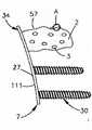
图11A是植入体系统的侧视图,该植入体系统包括表示为骨固定板的可膨胀植入体,表示该植入体处于未膨胀结构;11A is a side view of an implant system comprising an expandable implant shown as a bone fixation plate, showing the implant in an unexpanded configuration;
图11B是图28A中所示的植入体系统的侧视图,该植入体系统植入下部骨中;FIG. 11B is a side view of the implant system shown in FIG. 28A implanted in the lower bone;
图11C是图28B中所示的植入体系统的侧视图,表示植入体处于膨胀结构;Figure 11C is a side view of the implant system shown in Figure 28B, showing the implant in an expanded configuration;
图12A是图12B中所示的区域A的放大侧剖图;Figure 12A is an enlarged side sectional view of area A shown in Figure 12B;
图12B是植入体系统的侧视图,该植入体系统包括可膨胀植入体,该可膨胀植入体有在区域A处表示的骨生长区域;Fig. 12B is the side view of implant system, and this implant system comprises expandable implant body, and this expandable implant body has the bone growth area represented at area A place;
图12C是图12A中所示的植入体系统的侧视图,表示植入下部骨中和随后膨胀;Figure 12C is a side view of the implant system shown in Figure 12A, showing implantation in the lower bone and subsequent expansion;
图13A是具有植入体本体的植入体的侧剖图,根据另一实施例,该植入体本体限定了多孔包装件;13A is a side cross-sectional view of an implant having an implant body defining a porous package according to another embodiment;
图13B是图13A中所示的植入体的一部分的放大侧剖图;Figure 13B is an enlarged side cross-sectional view of a portion of the implant shown in Figure 13A;
图13C是类似于图13A的植入体的侧剖图,但是包括多个腔室;Figure 13C is a side cross-sectional view of an implant similar to Figure 13A, but including multiple chambers;
图14A是植入体组件的侧剖图,该植入体组件包括可膨胀植入体,该可膨胀植入体有由PLLA包封部限定的多个腔室,这些腔室嵌入多孔包装件中;14A is a side sectional view of an implant assembly comprising an expandable implant having a plurality of chambers defined by a PLLA envelope embedded in a porous package middle;
图14B是图14A中所示的植入体的可膨胀部分的侧剖图;Figure 14B is a side sectional view of the expandable portion of the implant shown in Figure 14A;
图14C是图14B中所示的植入体的可膨胀部分的示意侧剖图;Figure 14C is a schematic side sectional view of the expandable portion of the implant shown in Figure 14B;
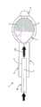
图15A是根据可选实施例构成的植入体系统的透视图,该植入体系统包括可膨胀植入体和膨胀组件,该膨胀组件包括膨胀装置、注射装置和能量发射器;15A is a perspective view of an implant system constructed in accordance with an alternative embodiment, the implant system comprising an expandable implant and an expansion assembly comprising an expansion device, an injection device, and an energy transmitter;
图15B是图15A中所示的植入体系统的侧剖图;Figure 15B is a side sectional view of the implant system shown in Figure 15A;
图15C是图15A中所示的可膨胀植入体和膨胀装置的放大侧剖图;Figure 15C is an enlarged side sectional view of the expandable implant and expansion device shown in Figure 15A;
图15D是图15C中所示的膨胀装置的侧剖图;Figure 15D is a side sectional view of the expansion device shown in Figure 15C;
图16A是与图15A中所示的可膨胀植入体类似的可膨胀植入体的侧剖图,但是根据另一实施例构成,该植入体表示处于未膨胀状态;Figure 16A is a side cross-sectional view of an expandable implant similar to that shown in Figure 15A, but constructed in accordance with another embodiment, the implant shown in an unexpanded state;
图16B是植入体系统的侧剖图,该植入体系统包括图16A中所示的可膨胀植入体,并表示膨胀装置与植入体可操作地连接;Figure 16B is a side sectional view of the implant system comprising the expandable implant shown in Figure 16A and showing that the expansion device is operatively connected to the implant;
图16C是图5B中所示的植入体系统的侧剖图,表示植入体处于膨胀结构;Figure 16C is a side sectional view of the implant system shown in Figure 5B, showing the implant in an expanded configuration;
图17A是图16A中所示的植入体的侧视图,该植入体以未膨胀结构植入椎间空间中;17A is a side view of the implant shown in FIG. 16A implanted in the intervertebral space in an unexpanded configuration;
图17B是图16B中所示的植入体系统的侧视图,该植入体系统植入图17A中所示的椎间空间中;17B is a side view of the implant system shown in FIG. 16B implanted in the intervertebral space shown in FIG. 17A;
图17C是图17B中所示的植入体系统的侧视图,表示植入体处于膨胀结构;以及Figure 17C is a side view of the implant system shown in Figure 17B, showing the implant in an expanded configuration; and
图17D是图17C中所示的植入体的侧视图,其中能量发射器已经从植入体上除去。Figure 17D is a side view of the implant shown in Figure 17C, with the energy emitters removed from the implant.
具体实施方式Detailed ways
在下面的说明中频繁使用的术语的定义如下:Definitions of frequently used terms in the description below are as follows:
光电导体:这里使用的术语光电导体是指柔性或刚性的光导结构,例如玻璃纤维电缆、反射软管(例如纳米管),该光导结构传导光,并可用于将电磁辐射从源传递给植入体本体7。为了引导光穿过光电导体进入植入体本体7直至所需点,在植入体中的光电导体可以一方面实际上传导光,例如意味着传导到销的尖端,然后在该处分配光,以便到达腔室3的内表面,例如通过散射。Photoconductor: The term photoconductor is used here to refer to flexible or rigid light-conducting structures such as fiberglass cables, reflective hoses (e.g. nanotubes) that conduct light and can be used to transfer electromagnetic radiation from a source to an implant body body7. In order to guide the light through the photoconductor into the
光源:这里使用的光源是指任何电磁辐射源,例如白炽灯泡、蒸气发射灯、二极管、半导体、电火花、火焰、阳光等。Light source: Light source as used here refers to any source of electromagnetic radiation such as incandescent light bulbs, vapor emitting lamps, diodes, semiconductors, electric sparks, flames, sunlight, etc.
激光:激光是优选的能量源,因为它们通常只发射很窄的限定频率电磁辐射。因此,植入体的非吸收部分的一个发色团(或者多个,直到很多发色团)的吸收波谱和本体周围的吸收波谱可以相互调谐。在优选用途中,激光在优选是单色频率中辐射,该单色频率只由植入体吸收,由发色团强烈吸收,而周围环境几乎不吸收。这能够向植入体中的不同区域供给不同发色团,并可以通过根据情况需要的电磁辐射频率来特别加热它们。Lasers: Lasers are the preferred energy source because they typically emit only narrowly defined frequencies of electromagnetic radiation. Thus, the absorption spectrum of one chromophore (or multiple, up to many chromophores) of the non-absorbing part of the implant and the absorption spectrum of the surrounding bulk can be tuned to each other. In a preferred application, the laser light is radiated in a preferably monochromatic frequency which is absorbed only by the implant, strongly by the chromophore, and hardly absorbed by the surroundings. This makes it possible to supply different chromophores to different regions in the implant and to heat them specifically by the frequency of electromagnetic radiation required by the situation.
发色团:这里使用的术语发色团是指添加在聚合物上或涂覆在聚合物上的颜色或色素,以便吸收电磁辐射和将它转变成热量。在一种用途中,物质能够添加或涂覆在植入体上,而没有发色团特性。不过,当引入人体内时,这些物质在与人体接触时变化,例如作为对身体组织的pH值的反应以及对身体盐、身体水分或身体温度的反应,且这使得物质褪色,并使得它能吸收电磁辐射。因此,与身体接触的区域能够变热,因为植入体在该温度点褪色。发色团的实例包括:叶绿素、碳黑、石墨、荧光素、亚甲基蓝、靛青绿、曙光红、曙光红Y(514nm)、ethyleosine(532nm)、吖啶、吖啶橙、铜酞菁、铬-钴-氧化铝、柠檬酸亚铁铵、焦榈酚、苏木浸膏、叶绿素-铜复合体、D&C蓝No.9、D&C绿No.5、[酞化青(2-)]铜、D&C蓝No.2、D&C蓝No.6、D&C绿No.6、D&C紫No.2、D&C黄No.10。某些荧光发色团在特定环境中并不吸收电磁辐射,但是辐射从周围环境、聚合物或任意另外引入的发色团吸收的光。Chromophore: The term chromophore as used herein refers to a color or pigment added to or coated on a polymer in order to absorb electromagnetic radiation and convert it into heat. In one use, a substance can be added or coated on an implant without chromophore properties. However, when introduced into the human body, these substances change on contact with the human body, for example as a reaction to the pH of body tissues and in response to body salt, body moisture or body temperature, and this causes the substance to fade and make it Absorbs electromagnetic radiation. Therefore, the areas in contact with the body can become hot, as the implant discolors at this point. Examples of chromophores include: chlorophyll, carbon black, graphite, fluorescein, methylene blue, indigo green, eosin, eosin Y (514nm), ethyleosine (532nm), acridine, acridine orange, copper phthalocyanine, chromium- Cobalt-Alumina, Ferrous Ammonium Citrate, Pyropalmitol, Hematoxylin Extract, Chlorophyll-Copper Complex, D&C Blue No.9, D&C Green No.5, [Phthalocyanine (2-)] Copper, D&C Blue No.2, D&C Blue No.6, D&C Green No.6, D&C Purple No.2, D&C Yellow No.10. Certain fluorescent chromophores do not absorb electromagnetic radiation in a particular environment, but radiate light absorbed from the surrounding environment, polymer, or any additionally introduced chromophore.
吸光、无色聚合物:这里使用的吸光聚合物是指自身具有吸收某种波长光的特性的聚合物,而并不添加发色团。聚合物能够预先加热至褪色点,因此能够吸收更多光。聚合物能够局部碳化或焦糖化,并因此能吸光。Light-absorbing, colorless polymer: The light-absorbing polymer used here refers to a polymer that itself has the property of absorbing a certain wavelength of light without adding a chromophore. The polymer can be preheated to the point of fading, so it absorbs more light. Polymers can be partially carbonized or caramelized, and thus absorb light.
参考图1A-2D,植入体系统1包括骨固定装置或植入体34以及能量发射器36,该能量发射器36设置成与植入体34可操作地连接,以便向植入体34提供能量。植入体34包括植入体本体7,该植入体本体7表示为沿中心纵向轴线9为细长的。植入体本体7能够为基本圆柱形或棱柱形,或者根据需要限定任意合适的可选几何形状。植入体本体7限定了第一和前端10以及第二或后端11,该第二或后端11沿纵向轴线9与前端10纵向间隔开。这里,前端10能够称为布置在后端11的远侧,后端11能够称为布置在前端10的近侧。1A-2D, the
植入体本体7限定了可膨胀部分2,该可膨胀部分2布置在后端11的纵向远侧的位置处。可膨胀部分2包括内表面37,该内表面37再限定内部腔室3的外周,该内部腔室3的尺寸和形状能够根据需要来设置。例如,腔室3能够为基本圆柱形或矩形。内部腔室3设置成充满可生物相容的膨胀流体5,该膨胀流体5能够例如提供为普通盐溶液。腔室3布置在植入体本体7的前端10的近侧,并在它的纵向前端处开口。因此,可以说腔室3开口于植入体本体7的前端10处,并纵向穿透至植入体本体7内深度T(从前端10朝着后端11测量)。可生物相容的膨胀流体5能够注入腔室3的前端内。腔室3能够布置在纵向轴线9上,如图所示。The
植入体34还包括帽8,该帽8能够固定在植入体本体7上,例如固定在植入体本体7的前端10上,以便封闭和密封内部腔室3。帽8有:插入部分15,该插入部分15适合装配至腔室3中;以及尖端部分16,该尖端部分16限定了植入体34的尖端部分。植入体本体7、腔室3和帽8表示为沿纵向轴线9彼此向远侧间隔开。帽8能够例如通过焊接来固定在植入体本体7的前端10上,以便封闭和密封腔室3。The
另外,植入体34包括限定于植入体本体7中的内部空腔12,该内部空腔12从后端11朝着前端10纵向向远侧延伸,并终止于与腔室3间隔开的位置处,以使得空腔12与内部腔室3纵向对齐。内部空腔12设置成接收能量发射器36,该能量发射器36例如能够为电磁辐射发射器14(例如光电导体),如图2C中所示,或者为热发射器17(见图4A-4B)。由下面的附图可知,能量发射器36设置成向植入体34提供能量,从而在植入后使得植入体本体7的至少一部分膨胀。根据示例实施例,内部腔室3限定了植入体本体7的可膨胀部分2,该可膨胀部分2设置成在能量发射器36向植入体34提供能量之后膨胀。In addition, the
如图1A-2D中所示,内表面37能够由能量吸收部件4涂覆或以其它方式覆盖,该能量吸收部件4例如为一层发色团。植入体本体7能够由任意合适材料来制造,例如聚合物材料,例如PMMA,该PMMA为透明,因此植入体本体7能够在空腔12和腔室3之间的位置处用作光电导体和光扩散器。因此,在电磁辐射发射器14向植入体本体7施加光之后,光通过植入体本体7传导,直到它到达内表面37。As shown in Figures 1A-2D, the
膨胀流体5能够在第一或初始状态中呈液体形式。如图2B-C中所示,能量105供给植入体本体7的可膨胀部分2和供给腔室3中的膨胀流体5将使得膨胀流体5的温度升高至足够水平,这使得膨胀流体5蒸发至第二状态的气体。因此,应当知道,当液态膨胀流体5蒸发成气体时,可生物相容的流体的压力增加。植入体本体7的温度增加和膨胀流体5增加的压力(由于蒸发)将使得植入体本体7的可膨胀部分2塑性膨胀。在来自能量发射器26的能量中断之后,膨胀流体5随后冷却,植入体本体7的已膨胀部分2将由于植入体本体7的塑性变形而保持在它的膨胀状态(图2D)。因此,尽管膨胀流体5能够冷凝至第三状态的液体,可膨胀部分2仍然由于塑性变形而保持膨胀。The
参考图3A-3G,植入体系统1能够设置成将植入体34固定在下部骨中。例如,通过植入体系统1来使得受损的椎骨本体13稳定的方法能够包括以下步骤:Referring to Figures 3A-3G, the
i)在要治疗的椎骨本体13中产生空腔20;i) creating a
ii)将处于未膨胀状态的植入体本体7插入空腔20中(图3A);ii) inserting the
iii)将能量发射器36(例如成光电导体14的形式)插入植入体本体7中,其中,该光电导体14与能量源(例如激光器)连接(图3B);iii) Inserting an energy transmitter 36 (for example in the form of a photoconductor 14 ) into the
iv)供给由能量发射器36发射的能量,以便增加膨胀流体5的温度,从而增加在植入体34的一个或多个腔室3中的内部蒸气压力,直到植入体34达到它的膨胀状态(图3C-3F);以及iv) supplying energy emitted by the
v)从植入体本体7中取出能量发射器(图3G)。v) Remove the energy transmitter from the implant body 7 (Fig. 3G).
下面参考图4A-B,空腔12能够从后部部分11朝着前部部分10纵向向远侧或向前延伸,并终止于邻近尖端部分16的位置处。尖端部分16表示为与植入体本体7成一体。植入体本体7限定了多个内表面37,这些内表面37限定了相应多个内部腔室3。腔室3能够根据需要限定任意尺寸和形状,并能够相对于一个或多个(直到全部)其它腔室3具有相同或不同的尺寸和形状。腔室3表示为圆形,例如球形或椭圆形,且能够相对于纵向轴线9偏离。也可以说,腔室3的形状设置为多个气泡,这些气泡结合或捕获于植入体本体7的周边壁25中。周边壁25相对于中心轴线9布置在腔室12的外侧,并沿横向或径向方向(相对于纵向轴线9成角度偏离,例如垂直)与空腔12对齐。因此,可以说,周边壁25包围或基本包围空腔12。Referring now to FIGS. 4A-B , the
腔室3沿周边壁25分布。因此腔室3限定在植入体本体7的基本整个长度上延伸的可膨胀部分2。如图4B中所示,空腔设置成接收能量发射器36,该能量发射器36表示为插入空腔12中的电加热器17。应当知道,植入体34的一部分能够在并不形成可膨胀部分2的部分的区域处没有腔室3,且植入体34因此能够限定多个可膨胀部分2或者至少一个可膨胀部分。能量发射器36能够设置成加热器17,该加热器17设置成向布置于腔室3中的膨胀流体5提供热量,从而使得流体从液体蒸发成气体,并以上述方式使得可膨胀部分2膨胀。The
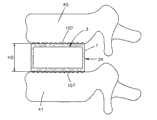
下面参考图5A-5C,植入体本体7能够基本形成为立方体,具有沿纵向轴线9间隔开的相对外壁18,当植入体34处于第一或未膨胀状态时,该相对外壁18朝向彼此凹形弯曲。在施加能量(该能量成例如由能量发射器36提供的热量的形式)的过程中,膨胀流体5蒸发,因此在腔室3中的内部压力增加。压力增加使得凹形弯曲的周边壁18向外凸出,以使得植入体34实现第二膨胀状态,其中,周边壁18基本为平的,或者比当植入体34处于第一未膨胀状态时更平。因此,植入体本体7的可膨胀部分从在相对骨接合表面107之间具有第一高度H1的第一状态膨胀至在相对骨接合表面107之间具有第二高度H2的第二状态,该第二高度H2大于第一高度H1。在第二状态中,平的周边壁18具有更大的变形阻力。Referring now to FIGS. 5A-5C , the
参考图6A-6D,在图5A-5C中所示的植入体34能够设置为椎间植入体,并插入布置在一对相邻椎骨40和41之间的椎间盘空间39中,使得骨接合表面107与相应椎骨端板接合。植入体34能够如上述膨胀,使得植入体本体7在植入体34未膨胀时限定第一高度H1,并在植入体34膨胀之后限定比第一高度H1更大的第二高度H2,从而提供对椎间盘空间39的高度恢复。Referring to FIGS. 6A-6D , the
下面参考图7A-7B,腔室3的形状能够设置为分别结合在沿纵向轴线9间隔开的相对第一和第二端部部分22和23中的气泡,该第一和第二端部部分22和23限定了植入体本体7的相应可膨胀部分。植入体本体7限定了中间部分109,该中间部分109沿纵向布置在端部部分22和23之间,且没有腔室3。应当知道,腔室3能够根据需要可选择地布置在第一和第二端部中的一个内。因此,可以说,植入体34包括布置在植入体本体7的至少一个第一和第二端部中的多个腔室。植入体本体7的第一和第二包含腔室的端部22和23能够由气隙间隔开和/或由植入体本体材料7(该植入体本体材料7没有腔室3,或者以其它方式包含比布置在植入体本体7的第一和第二端部部分22和23中更少的腔室3)间隔开。而且,植入体本体7的第一和第二端部部分22和23能够具有基本相等数目的腔室3,或者具有比另一端部部分少或多的腔室3。换句话说,各第一和第二端部部分22和23可以设置成与另一端部部分膨胀相同距离,或者与另一端部部分膨胀不同距离(例如更大或更小)。还应当知道,中间部分109能够没有腔室3,如图所示,或者能够包括一个或多个(例如多个)腔室3,使得中间部分109能够与一个或两个端部部分22和23基本相等地膨胀,或者与一个或两个端部部分22和23不同地膨胀(例如更大或更小)。Referring now to Figures 7A-7B, the
腔室3表示为均匀地分布在第一和第二端部部分22和23中,尽管应当知道,腔室3能够根据需要不规则地分布。根据示例实施例,腔室3覆盖植入体本体7的基本全部截面。植入体34还能够包括布置在第一和第二端部部分22和23中的一个或两个处的能量吸收部件4。如图7B中所示,当能量105例如通过激光器或可选的能量发射器而提供给能量吸收部件4时,第一和第二端部部分22、23以上述方式沿横过纵向轴线9的方向膨胀,从而使得植入体本体7成狗骨形。能量源能够以上述方式插入第一端部部分22中、以上述方式插入第二端部部分中、或者插入两个端部部分22和24中(如果需要的话)。The
下面参考图8,植入体34能够包括多个腔室3,这些腔室3能够根据需要可选地成形,并能够例如沿与纵向轴线9基本平行的方向为细长的,以便沿横过腔室3细长方向的方向(例如相对于纵向轴线9成角度偏离或者基本横过纵向轴线9)比沿与腔室3的细长方向基本平行的方向(例如基本平行于纵向轴线9)更多地膨胀。植入体系统1还能够包括能量发射器36,如上所述,且还能够包括辅助植入体,例如可膨胀(例如聚合的)椎间植入体19,该可膨胀椎间植入体19接收植入体34。在该方面,应当知道,植入体34对椎间植入体19提供膨胀力,从而使得椎间植入体19在椎间盘空间39中膨胀。特别是,椎间植入体19限定了孔24,该孔24的尺寸设置成接收植入体本体7,特别是接收植入体本体7的可膨胀部分2。能够提供为电热发射器17的能量发射器36向植入体本体7的可膨胀部分2施加呈热量形式的能量,从而使得腔室3以上述方式膨胀。在腔室3已经随后冷却之后,植入体本体7的可膨胀部分2能够从已经塑性变形的椎间植入体19上除去。Referring now to FIG. 8 , the
下面参考图9A,植入体34能够提供为椎间植入体19,该椎间植入体19包括:植入体本体7,该植入体本体7限定了内部空心空隙43;以及可膨胀部分2,该可膨胀部分2布置在空隙43内。当可膨胀部分2处于它的未膨胀状态时,该可膨胀部分2能够有比空隙43小的高度。植入体本体7还包括第一或上部引导部分45a和第二或下部引导部分45b,以使得第一或上部槽道47a从空隙43向上穿过上部引导部分45a延伸,并使得第二或下部槽道47b从空隙43向下穿过下部引导部分45b延伸。植入体本体7还包括第一或上部可膨胀部分或者滑动器部件26a以及第二或下部可膨胀部分或滑动器部件26b,它们分别至少局部布置在第一和第二槽道47a和47b中。当植入体34处于它的未膨胀状态时,第一和第二滑动器部件26a和26b凸出至内部空心空间中,并接触可膨胀部分2。而且,在未膨胀状态中,滑动器部件26a-b并不分别凸出超过上部和下部引导部分45a-b的上表面和下表面。Referring now to Figure 9A, the
如图所示,滑动器部件26a-b能够基本与引导部分45a-b的上表面和下表面平齐,尽管滑动器部件26a-b能够根据需要可选择地从引导部分45a-b的上表面和下表面凹入或者能够延伸超过该上表面和下表面。植入体34能够根据需要包括分布在可膨胀部分2中的至少一个(例如多个)腔室3。为了使得植入体34膨胀,能量以上述方式施加给可膨胀部分2。在可膨胀部分2的膨胀过程中,可膨胀部分2将滑动器部件26a-b分别向外离开内部空隙43朝着相邻的上部和下部椎骨本体推压。滑动器部件26a-b限定了相应外部接触表面,该外部接触表面包括多个齿29,以便使得可膨胀部分26和(因此)椎间植入体34初始锚固在椎骨中。在膨胀流体5冷却之后,已膨胀部分2和椎间植入体19由于塑性变形而保持膨胀状态。As shown, the slider members 26a-b can be substantially flush with the upper and lower surfaces of the guide portions 45a-b, although the slider members 26a-b can alternatively be positioned from the upper surfaces of the guide portions 45a-b as desired. The upper and lower surfaces are recessed or are capable of extending beyond the upper and lower surfaces. The
下面参考图9B,应当知道,在图9A中所示的植入体34能够根据需要包括任意数目的上部和下部滑动器部件26。例如,如图9B中所示,植入体34包括两个上部滑动器部件26a和三个下部滑动器部件26b。因此,植入体34能够包括至少一个(例如多个)上部滑动器部件26a和至少一个(例如多个)下部滑动器部件26b。植入体34能够包括相同或不同数目的上部和下部滑动器部件26a和26b。Referring now to FIG. 9B, it should be appreciated that the
下面参考图10,植入体34能够提供为骨固定元件,该骨固定元件呈榫钉的形式,该榫钉包括第一和第二相对的可膨胀部分或偏转部件51a和51b,该第一和第二可膨胀部分或偏转部件51a和51b各自可塑性变形。偏转部件从植入体本体7的基部部分55向下延伸。植入体34还包括可膨胀部分2,该可膨胀部分2布置在位于偏转部件51a和51b之间的空间53中。植入体34包括布置在内部空心空间中的可膨胀部分2。两个可膨胀部件26形成限制内部空心空间的侧壁。在可膨胀部分2的膨胀过程中,可膨胀部分向外推压偏转部件51a和51b离开纵向轴线9,以便绕基部部分55朝着周围骨组织铰接运动,以使得植入体34能够类似于榫钉锚固在例如骨中的孔内。Referring now to FIG. 10 , the
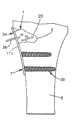
下面参考图11A-11C,植入体34能够设置为骨板111,使得植入体本体7包括骨板部分27,并限定了可膨胀部分2,该可膨胀部分2从骨板部分27向外伸出。植入体系统1还能够包括至少一个骨锚固件30,例如多个骨锚固件30,表示为骨螺钉,该骨锚固件30从骨板部分27伸出,并设置成附接在下部骨6上,以便提供骨锚固。骨板部分27能够限定多个孔,这些孔设置成接收骨锚固件30。可膨胀部分2能够提供初始的骨锚固,且可膨胀部分2能够包括多个腔室3,如上所述。植入体34能够以它的未膨胀状态插入空腔20中,该空腔20例如由骨的缺陷产生。在骨板部分27通过骨锚固件30而固定在下部骨6上之后,可膨胀部分2能够以上述方式通过从能量发射器36向可膨胀部分2供给能量而膨胀。Referring now to Figures 11A-11C, the
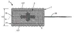
下面参考图12A-12C,植入体本体7能够包括多个宏观结构或纤维28,这些宏观结构或纤维28从可膨胀部分2的外表面57向外延伸,并能够促进或方便新骨在其上生长。这样的新骨生长能够用于增加在植入体34和骨6之间的界面的稳定性和减小微观运动。可膨胀部分2能够有这样的形状,在膨胀过程中,该形状适应骨缺陷或空腔20的形状。可膨胀部分2能够在需要时可重新吸收。另外,骨板部分27和骨锚固件30中的任意一个或两个能够根据需要可重新吸收。合适的可重新吸收材料能够包括例如聚交酯(PLA)族或聚己酸内酯(PCL)族。Referring now to Figures 12A-12C, the
下面参考图13A-13B,植入体34包括植入体本体7,该植入体本体7具有可膨胀部分2,该可膨胀部分2能够由PLLA(聚乙交酯)来制造。植入体本体7能够限定具有开口孔的包装件32以及嵌入包装件32中的长圆形或细长形腔室3。植入体34能够包括单个腔室3,如图13A中所示,或者包括设置为气泡(当未膨胀时,该气泡能够为基本球形或者可选的形状)的多个腔室3,如图13C中所示。腔室3由设置为硬包封部31的外周边限定,该腔室装满膨胀流体5,例如水。包封部31在加热过程中软化,并能够在冷却时再次硬化,以便提供稳定性。包封部31能够由PLLA(聚乙交酯)来制造。包装件32能够是具有开口孔的海绵状材料,或者能够是颗粒或微粒的涂层33,如图13B中所示。涂层33的颗粒或微粒能够由磷酸钙制造,例如TCP(磷酸三钙)或磷灰石,例如HAP(羟磷灰石)。因此,包装件32能够用于提供骨/植入体界面,该骨/植入体界面能够促进新骨生长,并能够提供植入体34至骨上的附加锚固(植入体34插入该骨中)。Referring now to Figures 13A-13B, the
下面参考图14A-14C,植入体34能够提供为骨板111,该骨板111包括具有骨板部分27的植入体本体7,且植入体本体7从限定可膨胀部分2的骨板部分27向外伸出。可膨胀部分2能够填充至下部骨6的空腔20中。骨板27能够以上述方式通过多个骨锚固件30(例如骨螺钉)而附接在骨6上。当可膨胀部分2膨胀时,骨板部分27防止植入体34凸出空腔20外。以上述方式,可膨胀部分2能够包括至少一个腔室3,例如多个腔室3,该腔室3由提供为包封部31的封闭外周边来限定,该包封部31由PLLA(聚乙交酯)制造,该腔室嵌入包括海绵状材料(具有开口孔)的包装件32中。在可膨胀部分2已经膨胀和随后冷却之后,植入体34设置成承受更大的机械应变。例如,一旦包封部31冷却至低于它的玻璃态转变温度,聚合物(例如PLLA)将硬化,因此能够在没有内部增压气体和并不经历变形的情况下承受更大力。Referring now to FIGS. 14A-14C , the
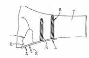
参考图15A-15D,根据可选实施例的可膨胀植入体系统50包括可膨胀植入体54和膨胀组件52,该膨胀组件52包括膨胀装置56、注射装置58和能量发射器61。植入体54限定了内部空腔59,该内部空腔59设置成接收膨胀装置56,以便使得膨胀组件52与植入体54可操作地连接,从而使得膨胀组件52能够在操作过程中使植入体54膨胀。Referring to FIGS. 15A-15D , an
植入体54包括植入体本体60,该植入体本体60沿中心纵向轴线62沿纵向为细长的。植入体本体60能够为圆柱形或棱柱形,或者能够根据需要限定任意可选的合适形状。植入体本体60限定了第一或前端64以及纵向相对的第二或后端66。植入体本体60限定了腔室59,该腔室59沿纵向轴线62纵向同轴线地延伸。腔室59限定了具有孔70的进口部分68,该孔70布置成邻近植入体本体60的、位于第二端部66处的外表面72。进口部分68设置成接收膨胀装置56,从而允许膨胀装置56插入腔室59中。植入体本体60限定了可膨胀部分74,该可膨胀部分74与腔室59操作对齐,该可膨胀部分74布置成邻近进口部分68和与进口部分68同延地延伸。腔室59在植入体54的第一端部处或附近封闭。植入体本体60包括内螺纹76,该内螺纹76伸入腔室59中,以便限定接合部件,该接合部件设置成与膨胀装置56的、呈外螺纹78形式的相应接合部件匹配。The
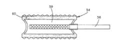
膨胀装置56包括杆形套筒80,该杆形套筒80沿中心纵向轴线82沿纵向是细长的,当膨胀装置56插入植入体54中时,该中心纵向轴线82能够与植入体54的中心纵向轴线62对齐。膨胀装置56限定了第一或前端84以及第二或后端86,该第二或后端86与前端84纵向间隔开。套筒80包括基本环形或管形的周边壁88,该周边壁88限定了中心内部开口90,该中心内部开口90提供在前端84处封闭的凹部。套筒80限定了至少一个径向穿孔92,例如多个径向穿孔92,该径向穿孔92穿透周边壁88。The
因此,当套筒80定位在植入体54的腔室59中时,从套筒80的后端86注入中心开口90的可生物相容膨胀流体94(例如液体或蒸气)能够穿过孔92并透入腔室59中。套筒80限定了:第一或前部部分96,该第一或前部部分96能够由膨胀装置56的前端84封闭;以及纵向相对的第二或后部部分98,该第二或后部部分98包括外螺纹78,该外螺纹78可与腔室59的进口部分68的内螺纹76接合。因此,通过使得套筒80的外螺纹78旋转和拧入进口部分68的内螺纹76中,套筒80能够以流体密封的方式固定在植入体54上。因此,膨胀装置56能够将增压膨胀流体94(例如液体或蒸气)注入腔室59的可膨胀部分74中。另外,膨胀装置56能够包括加热部件100,例如电加热部件,该加热部件布置在套筒80上,并设置成向腔室和(因此向)注入的可生物相容流体施加热量。根据一个实施例,加热部件100包括穿过套筒的后部部分98延伸的导电布线102。Thus, when the
下面参考图15B,膨胀装置56包括手柄104,该手柄104直接或间接地与套筒80连接。能量发射器61能够包括布置在手柄104中的集成电源106(例如电池)。电源106设置成向导电布线102供给电能,并因此向加热部件100供给电能。这样,可膨胀植入体系统50能够包括能量发射器61,该能量发射器61包括加热部件电源100和106,并设置成供给发射能量,该发射能量增加膨胀流体94的温度。膨胀装置56还包括注射装置58,该注射装置58有套管108、充满流体94的缸110以及可在缸110中移动的活塞112。套管108附接在缸110的前端上,以使得套管108能够插入套筒的后部部分98中和插入套筒80的中心开口90中。活塞112提供了促动器,该促动器能够朝着套管108被向前按压至缸110中,以便提供压力,该压力推压膨胀流体94穿过套管108进入套管80的中心开口90中。Referring now to FIG. 15B , the
在使得膨胀装置56固定于植入体54上之后,加热部件100被启动,以便向植入体54传送热量,直到植入体54充分软化和可塑性变形。例如,加热部件100的温度能够设置为比植入体本体60的温度高的值,使得从加热部件传送的热量能够使得植入体本体60的温度升高,从而使得植入体本体60软化,该植入体本体60能够由聚合物材料制造。随后,膨胀流体94能够注入套筒80的中心开口90中,使得在植入体本体60软化之后,膨胀流体94在腔室59中产生膨胀力,该膨胀力使得植入体54膨胀。在该方面,应当知道,流体94能够在植入体本体60软化之前或之后注入腔室59中。After securing the
膨胀流体94通过套筒80的中心内部开口90注射使得流体94穿过孔92运行进入植入体54的腔室59中。例如,当膨胀流体94是液体时,膨胀流体94能够通过来自加热部件100的热量而被加热和蒸发,使得膨胀流体94转变成蒸气,该蒸气在腔室59中对植入体本体60产生膨胀力。膨胀力足以使得植入体本体60(例如在可膨胀部分74处)从第一状态膨胀至膨胀的第二状态。因此,膨胀力能够通过加热膨胀流体94来产生,直到膨胀流体94蒸发,以便产生膨胀力。An
一旦蒸发的流体已经使得植入体54膨胀至它的所需形状,加热部件100能够关闭。然后,植入体54能够冷却,使得植入体本体60的温度降低至低于它的玻璃态转变温度,从而使得植入体本体60硬化成刚性体。使得植入体54冷却将进一步使得加压的蒸气局部或完全冷凝或液化,从而降低内部腔室59中的压力。在植入体54冷却之后,膨胀装置56能够除去,且植入体54保持它的膨胀状态。当除去膨胀装置56时或者在除去膨胀装置56之后,一些或全部注射流体94也能够被排出或者以其它方式从植入体腔室59中去除。Once the evaporated fluid has caused the
尽管在一个实施例中通过使得提供为液体的流体94蒸发而产生膨胀力,但是应当知道,膨胀力能够根据可选实施例产生。例如,膨胀力能够通过加热流体(但是并不使得流体蒸发)而产生。例如,流体能够被注射为蒸气,从而随后加热蒸气将使得蒸气膨胀,由此产生膨胀力。在该方面,尽管流体是加热的蒸气(该加热蒸气施加膨胀力),但是应当知道,其它流体(例如液体)同样在加热时膨胀。因此,膨胀力能够通过加热流体94而产生,且在一些实施例中,热量能够使得流体蒸发。也可选择或者另外,膨胀力能够通过流体94的注射压力来产生,该注射压力在由注射装置58产生的压力下传递给腔室59。Although in one embodiment the expansion force is generated by evaporating
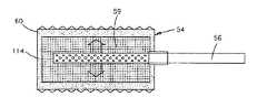
应当知道,植入体54能够根据需要采取任意尺寸和形状。例如,下面参考图16A-16C,植入体54的植入体本体60表示为基本立方体形状,包括相对的外壁114,当植入体54处于未膨胀状态时,该外壁114凹形弯曲。在以上述方式施加热量和增压的可生物相容流体时,植入体本体60膨胀,这使得相对壁114向外凸出,以便当植入体54处于膨胀状态时采取基本平的方位,或者采取比当植入体54处于未膨胀状态时平的结构。在第二状态中,更平的周边壁114具有更大的变形阻力。It should be appreciated that the
图17A-17D表示了根据图16A-16C的植入体54的实施例用作椎间植入体,该椎间植入体插入布置在一对相邻椎骨118和120之间的椎间盘空间116中。植入体54能够膨胀,如上所述,使得植入体本体60在植入体54处于未膨胀时限定第一高度H1,并在植入体54膨胀之后限定第二高度H2,该第二高度H2比第一高度H1更大,因此使椎间盘空间116的高度恢复。FIGS. 17A-17D show an embodiment of the
应当知道,骨固定套件能够提供为具有这里所述的一个或多个实施例的部件。例如,骨固定套件能够包括植入体,该植入体有限定一定体积的植入体本体。植入体本体限定了至少一个腔室,该腔室设置成保持处于一定压力的膨胀流体。套件还能够包括能量发射器,该能量发射器设置成向植入体施加能量,以便将热量传递给植入体本体。施加的能量使得膨胀流体的压力在该至少一个腔室内部增加,以便使得植入体本体的可膨胀部分膨胀。It should be appreciated that bone fixation kits can be provided as components having one or more of the embodiments described herein. For example, a bone fixation kit can include an implant having an implant body defining a volume. The implant body defines at least one chamber configured to maintain an inflation fluid at pressure. The kit can also include an energy transmitter configured to apply energy to the implant to transfer heat to the implant body. The applied energy increases the pressure of the inflation fluid inside the at least one chamber to expand the expandable portion of the implant body.
尽管已经详细介绍了各种实施例,但是应当知道,在不脱离例如由附加权利要求限定的本发明精神和范围的情况下可以进行多种变化、代替和改变。而且,本申请的范围并不局限于在说明书中所述的处理、机器、制造、物质组分、装置、方法和步骤的特殊实施例。本领域技术人员由前述说明很容易知道,执行基本相同功能或获得与这里所述的相应实施例基本相同结果的、目前存在或以后开发的处理、机器、制造、物质组分、装置、方法和步骤也可以使用。Although various embodiments have been described in detail, it should be understood that various changes, substitutions and alterations can be made therein without departing from the spirit and scope of the invention, for example as defined by the appended claims. Furthermore, the scope of the present application is not limited to the particular embodiments of the process, machine, manufacture, composition of matter, means, methods and steps described in the specification. Those skilled in the art will readily appreciate from the foregoing description that processes, machines, manufacture, compositions of matter, means, methods, and Steps can also be used.
Claims (56)
Applications Claiming Priority (5)
| Application Number | Priority Date | Filing Date | Title |
|---|---|---|---|
| US37224510P | 2010-08-10 | 2010-08-10 | |
| US37221910P | 2010-08-10 | 2010-08-10 | |
| US61/372,245 | 2010-08-10 | ||
| US61/372,219 | 2010-08-10 | ||
| PCT/US2010/058343WO2012021148A1 (en) | 2010-08-10 | 2010-11-30 | Expandable implant |
Publications (2)
| Publication Number | Publication Date |
|---|---|
| CN103068342Atrue CN103068342A (en) | 2013-04-24 |
| CN103068342B CN103068342B (en) | 2016-01-06 |
Family
ID=43639968
Family Applications (1)
| Application Number | Title | Priority Date | Filing Date |
|---|---|---|---|
| CN201080068526.3AExpired - Fee RelatedCN103068342B (en) | 2010-08-10 | 2010-11-30 | Expandable implant |
Country Status (8)
| Country | Link |
|---|---|
| US (1) | US9265616B2 (en) |
| EP (1) | EP2603175B1 (en) |
| JP (1) | JP5916726B2 (en) |
| KR (1) | KR101759509B1 (en) |
| CN (1) | CN103068342B (en) |
| BR (1) | BR112013000994A2 (en) |
| CA (1) | CA2807764C (en) |
| WO (1) | WO2012021148A1 (en) |
Cited By (1)
| Publication number | Priority date | Publication date | Assignee | Title |
|---|---|---|---|---|
| CN106994038A (en)* | 2017-05-23 | 2017-08-01 | 温州医科大学附属第二医院、温州医科大学附属育英儿童医院 | One kind remedies fixing device for vertebral arch pedicle of vertebral column broken wall |
Families Citing this family (29)
| Publication number | Priority date | Publication date | Assignee | Title |
|---|---|---|---|---|
| JP2879054B2 (en) | 1997-08-19 | 1999-04-05 | ヤンマー農機株式会社 | Harvester harvester |
| JP2900028B2 (en) | 1997-08-19 | 1999-06-02 | ヤンマー農機株式会社 | Harvester harvester |
| DE10154163A1 (en) | 2001-11-03 | 2003-05-22 | Advanced Med Tech | Device for straightening and stabilizing the spine |
| US7806900B2 (en) | 2006-04-26 | 2010-10-05 | Illuminoss Medical, Inc. | Apparatus and methods for delivery of reinforcing materials to bone |
| US8275594B2 (en)* | 2006-10-30 | 2012-09-25 | The Regents Of The University Of Michigan | Engineered scaffolds for intervertebral disc repair and regeneration and for articulating joint repair and regeneration |
| CA2669129C (en) | 2006-11-10 | 2014-09-16 | Illuminoss Medical, Inc. | Systems and methods for internal bone fixation |
| US7879041B2 (en) | 2006-11-10 | 2011-02-01 | Illuminoss Medical, Inc. | Systems and methods for internal bone fixation |
| AU2007356033B2 (en) | 2007-07-03 | 2014-05-29 | Synergy Biosurgical Ag | Medical implant |
| KR101617051B1 (en) | 2007-09-17 | 2016-04-29 | 씨너지 바이오써지컬 아게 | medical implant |
| US9427289B2 (en)* | 2007-10-31 | 2016-08-30 | Illuminoss Medical, Inc. | Light source |
| US8403968B2 (en) | 2007-12-26 | 2013-03-26 | Illuminoss Medical, Inc. | Apparatus and methods for repairing craniomaxillofacial bones using customized bone plates |
| BRPI1015207A2 (en)* | 2009-04-07 | 2016-05-03 | Illuminoss Medical Inc | photodynamic bone stabilization systems and methods for treating spine conditions |
| US8998924B2 (en) | 2009-04-16 | 2015-04-07 | Coalign Innovations, Inc. | Insertion handle for surgical implants |
| EP2467098A4 (en)* | 2009-08-19 | 2015-07-08 | Illuminoss Medical Inc | Devices and methods for bone alignment, stabilization and distraction |
| JP2013512048A (en) | 2009-11-30 | 2013-04-11 | シンセス ゲゼルシャフト ミット ベシュレンクテル ハフツング | Expandable implant |
| EP2654584A1 (en) | 2010-12-22 | 2013-10-30 | Illuminoss Medical, Inc. | Systems and methods for treating conditions and diseases of the spine |
| US8695726B2 (en) | 2010-12-29 | 2014-04-15 | Medical Enterprises LLC | Electric motor driven tool for orthopedic impacting |
| CN104519813A (en) | 2010-12-29 | 2015-04-15 | 澳擞技术有限责任公司 | Motor-driven tools for orthopedic impact |
| US8486149B2 (en)* | 2011-02-23 | 2013-07-16 | DePuy Synthes Products, LLC | Expandable interbody fusion implant |
| US20130023876A1 (en) | 2011-07-19 | 2013-01-24 | Illuminoss Medical, Inc. | Combination Photodynamic Devices |
| US8936644B2 (en) | 2011-07-19 | 2015-01-20 | Illuminoss Medical, Inc. | Systems and methods for joint stabilization |
| US8939977B2 (en) | 2012-07-10 | 2015-01-27 | Illuminoss Medical, Inc. | Systems and methods for separating bone fixation devices from introducer |
| US9687281B2 (en) | 2012-12-20 | 2017-06-27 | Illuminoss Medical, Inc. | Distal tip for bone fixation devices |
| US9247981B2 (en) | 2013-03-12 | 2016-02-02 | DePuy Synthes Products, Inc. | Laser type fixation member securement device and activation system, and related system and methods |
| JP2018110603A (en)* | 2015-05-21 | 2018-07-19 | テルモ株式会社 | Implant member |
| WO2017147602A1 (en) | 2016-02-26 | 2017-08-31 | Cimphoni Life Sciences LLC | Light emitting bone implants |
| US10285825B2 (en)* | 2016-04-07 | 2019-05-14 | Howmedica Osteonics Corp. | Surgical insertion instruments |
| EP3456297B1 (en) | 2017-09-15 | 2023-10-04 | Howmedica Osteonics Corp. | Instruments for expandable interbody implants |
| US11071572B2 (en) | 2018-06-27 | 2021-07-27 | Illuminoss Medical, Inc. | Systems and methods for bone stabilization and fixation |
Citations (6)
| Publication number | Priority date | Publication date | Assignee | Title |
|---|---|---|---|---|
| US20040186576A1 (en)* | 2003-03-20 | 2004-09-23 | Spineco, Inc., An Ohio Corporation | Expandable spherical spinal implant |
| CN1561185A (en)* | 2001-12-05 | 2005-01-05 | 马斯医药技术股份公司 | Intervertebral disk prosthesis or nucleus replacement prosthesis |
| US20060229628A1 (en)* | 2004-10-02 | 2006-10-12 | Csaba Truckai | Biomedical treatment systems and methods |
| US20070233250A1 (en)* | 2006-02-07 | 2007-10-04 | Shadduck John H | Systems for treating bone |
| US20070270953A1 (en)* | 2006-03-29 | 2007-11-22 | Sdgi Holdings, Inc. | Transformable spinal implants and methods of use |
| WO2008079864A1 (en)* | 2006-12-21 | 2008-07-03 | Warsaw Orthopedic, Inc. | Orthopedic implant devices curable in vivo |
Family Cites Families (14)
| Publication number | Priority date | Publication date | Assignee | Title |
|---|---|---|---|---|
| US5972015A (en) | 1997-08-15 | 1999-10-26 | Kyphon Inc. | Expandable, asymetric structures for deployment in interior body regions |
| US6964667B2 (en) | 2000-06-23 | 2005-11-15 | Sdgi Holdings, Inc. | Formed in place fixation system with thermal acceleration |
| US7294187B2 (en) | 2001-01-24 | 2007-11-13 | Ada Foundation | Rapid-hardening calcium phosphate cement compositions |
| CA2495404C (en) | 2002-08-15 | 2011-05-03 | Justin K. Coppes | Intervertebral disc implant |
| US6733533B1 (en) | 2002-11-19 | 2004-05-11 | Zimmer Technology, Inc. | Artificial spinal disc |
| AU2004212942A1 (en) | 2003-02-14 | 2004-09-02 | Depuy Spine, Inc. | In-situ formed intervertebral fusion device |
| US20060064170A1 (en)* | 2004-09-17 | 2006-03-23 | Smith Jeffrey A | Closed system artificial intervertebral disc |
| US20060089719A1 (en)* | 2004-10-21 | 2006-04-27 | Trieu Hai H | In situ formation of intervertebral disc implants |
| US7182783B2 (en)* | 2005-04-25 | 2007-02-27 | Sdgi Holdings, Inc. | Selectively expandable composite structures for spinal arthroplasty |
| US20060282166A1 (en) | 2005-06-09 | 2006-12-14 | Sdgi Holdings, Inc. | Compliant porous coating |
| US8496657B2 (en) | 2006-02-07 | 2013-07-30 | P Tech, Llc. | Methods for utilizing vibratory energy to weld, stake and/or remove implants |
| US20080269745A1 (en) | 2007-04-24 | 2008-10-30 | Osteolign, Inc. | Thermo-chemically activated intramedullary bone stent |
| EP2180850B1 (en) | 2007-07-25 | 2018-11-21 | Depuy Spine, Inc. | Expandable bone filler materials and methods of using same |
| JP2013512048A (en) | 2009-11-30 | 2013-04-11 | シンセス ゲゼルシャフト ミット ベシュレンクテル ハフツング | Expandable implant |
- 2010
- 2010-11-30BRBR112013000994Apatent/BR112013000994A2/enactiveSearch and Examination
- 2010-11-30KRKR1020137003152Apatent/KR101759509B1/ennot_activeExpired - Fee Related
- 2010-11-30CACA2807764Apatent/CA2807764C/ennot_activeExpired - Fee Related
- 2010-11-30WOPCT/US2010/058343patent/WO2012021148A1/enactiveApplication Filing
- 2010-11-30EPEP10793357.4Apatent/EP2603175B1/ennot_activeNot-in-force
- 2010-11-30JPJP2013524072Apatent/JP5916726B2/enactiveActive
- 2010-11-30USUS12/956,367patent/US9265616B2/ennot_activeExpired - Fee Related
- 2010-11-30CNCN201080068526.3Apatent/CN103068342B/ennot_activeExpired - Fee Related
Patent Citations (6)
| Publication number | Priority date | Publication date | Assignee | Title |
|---|---|---|---|---|
| CN1561185A (en)* | 2001-12-05 | 2005-01-05 | 马斯医药技术股份公司 | Intervertebral disk prosthesis or nucleus replacement prosthesis |
| US20040186576A1 (en)* | 2003-03-20 | 2004-09-23 | Spineco, Inc., An Ohio Corporation | Expandable spherical spinal implant |
| US20060229628A1 (en)* | 2004-10-02 | 2006-10-12 | Csaba Truckai | Biomedical treatment systems and methods |
| US20070233250A1 (en)* | 2006-02-07 | 2007-10-04 | Shadduck John H | Systems for treating bone |
| US20070270953A1 (en)* | 2006-03-29 | 2007-11-22 | Sdgi Holdings, Inc. | Transformable spinal implants and methods of use |
| WO2008079864A1 (en)* | 2006-12-21 | 2008-07-03 | Warsaw Orthopedic, Inc. | Orthopedic implant devices curable in vivo |
Cited By (2)
| Publication number | Priority date | Publication date | Assignee | Title |
|---|---|---|---|---|
| CN106994038A (en)* | 2017-05-23 | 2017-08-01 | 温州医科大学附属第二医院、温州医科大学附属育英儿童医院 | One kind remedies fixing device for vertebral arch pedicle of vertebral column broken wall |
| CN106994038B (en)* | 2017-05-23 | 2024-03-26 | 温州医科大学附属第二医院、温州医科大学附属育英儿童医院 | Be used for broken wall of backbone pedicle of vertebral arch to remedy fixing device |
Also Published As
| Publication number | Publication date |
|---|---|
| EP2603175B1 (en) | 2016-03-09 |
| JP5916726B2 (en) | 2016-05-11 |
| CA2807764A1 (en) | 2012-02-16 |
| JP2014500731A (en) | 2014-01-16 |
| US9265616B2 (en) | 2016-02-23 |
| CA2807764C (en) | 2018-01-02 |
| WO2012021148A1 (en) | 2012-02-16 |
| KR20130139849A (en) | 2013-12-23 |
| BR112013000994A2 (en) | 2017-07-11 |
| CN103068342B (en) | 2016-01-06 |
| US20120041557A1 (en) | 2012-02-16 |
| KR101759509B1 (en) | 2017-07-19 |
| EP2603175A1 (en) | 2013-06-19 |
Similar Documents
| Publication | Publication Date | Title |
|---|---|---|
| CN103068342B (en) | Expandable implant | |
| US10022228B2 (en) | Expandable implant | |
| US8480718B2 (en) | Curable orthopedic implant devices configured to be hardened after placement in vivo | |
| US7771476B2 (en) | Curable orthopedic implant devices configured to harden after placement in vivo by application of a cure-initiating energy before insertion | |
| US8758407B2 (en) | Methods for positioning a load-bearing orthopedic implant device in vivo | |
| US9161797B2 (en) | Bone treatment systems and methods | |
| CN101801280B (en) | Medical implant | |
| EP2023839A1 (en) | Reinforcement of boney material surrounding a bone implant | |
| JP2010514471A5 (en) |
Legal Events
| Date | Code | Title | Description |
|---|---|---|---|
| C06 | Publication | ||
| PB01 | Publication | ||
| C10 | Entry into substantive examination | ||
| SE01 | Entry into force of request for substantive examination | ||
| C14 | Grant of patent or utility model | ||
| GR01 | Patent grant | ||
| CF01 | Termination of patent right due to non-payment of annual fee | Granted publication date:20160106 Termination date:20201130 | |
| CF01 | Termination of patent right due to non-payment of annual fee |