CN103066450A - Multiport RJ Stacking Connectors with Interlock Mechanism - Google Patents
Multiport RJ Stacking Connectors with Interlock MechanismDownload PDFInfo
- Publication number
- CN103066450A CN103066450ACN2012104098832ACN201210409883ACN103066450ACN 103066450 ACN103066450 ACN 103066450ACN 2012104098832 ACN2012104098832 ACN 2012104098832ACN 201210409883 ACN201210409883 ACN 201210409883ACN 103066450 ACN103066450 ACN 103066450A
- Authority
- CN
- China
- Prior art keywords
- connector
- type female
- connectors
- connector body
- female connector
- Prior art date
- Legal status (The legal status is an assumption and is not a legal conclusion. Google has not performed a legal analysis and makes no representation as to the accuracy of the status listed.)
- Pending
Links
- 230000000295complement effectEffects0.000claimsdescription19
- 230000015572biosynthetic processEffects0.000claimsdescription5
- 238000005755formation reactionMethods0.000claimsdescription5
- DCMURXAZTZQAFB-UHFFFAOYSA-N1,4-dichloro-2-(2-chlorophenyl)benzeneChemical compoundClC1=CC=C(Cl)C(C=2C(=CC=CC=2)Cl)=C1DCMURXAZTZQAFB-UHFFFAOYSA-N0.000description11
- 238000003780insertionMethods0.000description7
- 230000037431insertionEffects0.000description7
- 238000000034methodMethods0.000description3
- 238000009434installationMethods0.000description2
- 238000012986modificationMethods0.000description2
- 230000004048modificationEffects0.000description2
- 230000004075alterationEffects0.000description1
- 238000003491arrayMethods0.000description1
- 230000000712assemblyEffects0.000description1
- 238000000429assemblyMethods0.000description1
- 230000005540biological transmissionEffects0.000description1
- 230000013011matingEffects0.000description1
Images


Landscapes
- Details Of Connecting Devices For Male And Female Coupling (AREA)
Abstract
Description
Translated fromChinese技术领域technical field
本发明涉及包括至少三排竖直堆叠的RJ连接器的多端口RJ连接器,其中竖直堆叠的RJ连接器具有延伸至多端口RJ连接器的底壁的相应的接触件以便插入到印刷电路板(PCB)内。本发明包括在可安装在PCB上的共同的连接器主体中所堆叠的至少三个RJ型凹入式连接器。每个多端口RJ连接器的连接器主体可以选择性地安装到另一个多端口RJ连接器的连接器主体上以便形成高密度的连接器。The present invention relates to a multiport RJ connector comprising at least three rows of vertically stacked RJ connectors, wherein the vertically stacked RJ connectors have corresponding contacts extending to the bottom wall of the multiport RJ connector for insertion into a printed circuit board (PCB) inside. The present invention includes at least three RJ-style female connectors stacked in a common connector body mountable on a PCB. The connector body of each multiport RJ connector is selectively mountable to the connector body of another multiport RJ connector to form a high density connector.
背景技术Background technique
RJ连接器是用于互联网和计算机产品的电连接器。RJ连接器还应用于电话产业。RJ connectors are electrical connectors used in Internet and computer products. RJ connectors are also used in the telephone industry.
模块化连接器普遍用于电话系统、数据网络和低速串行连接。这些连接器便宜、相对容易端接且易于插拔。模块化连接器典型地具有透明的塑料主体,该主体具有在连接时协力将插塞(凹入式连接器)和插头(凸出式连接器)锁定到位的凸片或弹簧锁栓以及锁栓缺口。Modular connectors are commonly used in telephone systems, data networks, and low-speed serial connections. These connectors are inexpensive, relatively easy to terminate, and easy to plug and unplug. Modular connectors typically have a clear plastic body with a tab or spring latch and a latch that cooperate to lock the plug (female connector) and plug (male connector) in place when connected gap.
按照科技产业领域所使用的术语,这些模块化插塞被称为“RJ”连接器。该命名约定从技术的角度而言不够精准,但是却被广泛使用。RJ是注册插座(registered jack)的首字母缩写,该注册插座是1970年代AT&T公司为将电话服务和设备分类而发展出的代码系统的一部分。被称为通用服务命令码(USOC)的这一系统使用以字母RJ开头的命名表示在建筑中插座的容量以及为了将它们与公用电话网络连接起来应该如何对它们配线。In terms used in the technology industry, these modular plugs are known as "RJ" connectors. This naming convention is technically imprecise, but it is widely used. RJ is an acronym for registered jack, which was part of a code system developed by AT&T in the 1970s to classify telephone service and equipment. Known as the Universal Service Order Code (USOC), the system uses designations beginning with the letters RJ to indicate the capacity of outlets in a building and how they should be wired to connect them to the public telephone network.
注册插座(RJ)是标准化物理网络接口,用于使电讯或数据设备与服务器连接的插座构造和配线图案均是由本地交换运营商或长途运营商提供的。这些连接器及其配线的标准化设计被称为RJ11、RJ14、RJ21、RJ45、RJ48等。这些接口标准中的很大部分常用于北美,尽管其中一些接口在全球范围内使用。A Registered Jack (RJ) is a standardized physical network interface. The socket configuration and wiring pattern used to connect telecommunications or data equipment to the server are provided by the local exchange operator or long-distance operator. The standardized designs for these connectors and their wiring are known as RJ11, RJ14, RJ21, RJ45, RJ48, etc. A large number of these interface standards are commonly used in North America, although some of these interfaces are used worldwide.
RJ型凹入式连接器具有供RJ型凸出式插塞插入以形成连接的插座壳体(或开口)。RJ型凹入式壳体具有许多可使用的构造,包括:单个端口;水平布置的一排两个端口;以及可堆叠式连接器,其是堆叠的RJ连接器的排。然而,在现有的构造和布置中,这些可堆叠式连接器仅由两排构成。RJ-style female connectors have a receptacle housing (or opening) into which an RJ-style male plug is inserted to make a connection. RJ style female housings are available in a number of configurations including: a single port; a row of two ports arranged horizontally; and a stackable connector, which is a row of stacked RJ connectors. However, in existing configurations and arrangements, these stackable connectors consist of only two rows.
发明内容Contents of the invention
本发明涉及容纳在连接器主体中的竖直堆叠的三个或更多个RJ型凹入式连接器,以便增加在单个组件或单元中RJ型凹入式连接器的密度和数量。由于RJ型凹入式连接器的密度增加,故而本发明还增加了需要延伸的接触针的数量,从而连接器的深度增大以提供用于将这些接触针容纳和收容在连接器主体中的空间。这些RJ型凹入式连接器的排通常具有保持连接器的尺寸最小化的对称的取向。在本发明中,连接器的对称的取向有助于使连接器主体具有节约空间的小的尺寸。The present invention relates to vertically stacking three or more RJ type female connectors housed in a connector body in order to increase the density and number of RJ type female connectors in a single assembly or unit. Due to the increased density of RJ type female connectors, the present invention also increases the number of contact pins that need to be extended, thereby increasing the depth of the connector to provide for accommodating and accommodating these contact pins in the connector body. space. The rows of these RJ-style female connectors generally have a symmetrical orientation that keeps the size of the connectors to a minimum. In the present invention, the symmetrical orientation of the connector contributes to the small, space-saving size of the connector body.
更具体地说,本发明包括位于连接器主体内的多个竖直堆叠的RJ型凹入式连接器,该连接器主体能够安装到类似堆叠的RJ型凹入式连接器的连接器主体上,以便增加端口的密度和数量。在一个非限制性实施例中,本发明的RJ型凹入式连接器在每个连接器主体内包括顶排RJ型凹入式连接器、中间排RJ型凹入式连接器和底排RJ型凹入式连接器,每个连接器主体可以安装到同样具有堆叠的三个RJ型凹入式连接器的另一个连接器主体上,从而实质上它们具有围绕和封入全部RJ型凹入式连接器的单个遮盖件。More specifically, the present invention includes a plurality of vertically stacked RJ-type female connectors within a connector body capable of being mounted to a connector body of similarly stacked RJ-type female connectors , in order to increase the density and number of ports. In one non-limiting embodiment, the RJ-type female connector of the present invention includes a top row of RJ-type female connectors, a middle row of RJ-type female connectors, and a bottom row of RJ-type female connectors within each connector body. type female connectors, each connector body can be mounted to another connector body that also has a stack of three RJ type female A single cover for the connector.
本发明还涉及多端口RJ连接器组件,该多端口RJ连接器组件包括接合在一起的多个多端口RJ连接器(连接器主体),每个多端口RJ连接器包括堆叠的三个RJ型凹入式连接器。多端口RJ连接器组件可以包括三端口、六端口、九端口、十二端口、十五端口、十八端口、二十一端口等构造。The present invention also relates to a multiport RJ connector assembly comprising a plurality of multiport RJ connectors (connector bodies) joined together, each multiport RJ connector comprising a stack of three RJ type Recessed connector. Multi-port RJ connector assemblies may include three-port, six-port, nine-port, twelve-port, fifteen-port, eighteen-port, twenty-one-port, etc. configurations.
可以预见到,每个多端口RJ连接器可以安装到另一个多端口RJ连接器或者包括USB、HDMI和SATA连接器在内的其他类型的连接器上。可以为全部安装使用同样的互锁结构。在一个非限定性实施例中,该互锁结构可以包括从多端口RJ连接器主体的一侧突出的塑料楔入件,该塑料楔入件插入并锁定在位于另一个多端口RJ连接器主体的另一侧上的槽内,该槽与该塑料楔入件对准相同的位置。因此,在安装USB、HDMI和SATA连接器时,突出的塑料楔入件对准相同的位置以完成安装。It is contemplated that each multiport RJ connector may mount to another multiport RJ connector or other types of connectors including USB, HDMI and SATA connectors. The same interlock structure can be used for all installations. In one non-limiting embodiment, the interlocking structure may include a plastic wedge protruding from one side of the body of the multiport RJ connector, the plastic wedge inserting and locking into the body of the other multiport RJ connector. In the slot on the other side of the plastic wedge, the slot is aligned in the same location as the plastic wedge. Therefore, when installing the USB, HDMI, and SATA connectors, the protruding plastic wedges line up in the same position to complete the installation.
在与USB、HDMI或SATA连接器组合以便将其接安装和锁定在一起时,可以保持包括三个RJ型凹入式连接器的多端口RJ连接器的相同的高度和尺寸。When combined with a USB, HDMI or SATA connector to mount and lock them together, the same height and size of the multi-port RJ connector including three RJ-type female connectors can be maintained.
本发明还涉及安装用于互联网和计算机产业的所有类型的连接器的方法。该方法包括:将容纳有三个RJ型凹入式连接器的连接器主体与容纳有两个或三个或更多个RJ型凹入式连接器的另一个连接器主体接合,以增加在单个多端口RJ型连接器组件中连接器的密度。The invention also relates to a method of installing all types of connectors used in the Internet and computer industry. The method includes: engaging a connector body accommodating three RJ-type female connectors with another connector body accommodating two or three or more RJ-type female connectors to increase the The density of connectors in a multiport RJ-style connector assembly.
更具体地说,提供一种多端口RJ连接器,其包括:连接器主体,其包括竖直堆叠的RJ型凹入式连接器,所述竖直堆叠的RJ型凹入式连接器从所述连接器主体的底部到顶部包括第一RJ型凹入式连接器、第二RJ型凹入式连接器和第三RJ型凹入式连接器;每个RJ型凹入式连接器在该RJ型凹入式连接器的开口内包括并排布置的多个具有接触部分的接触件,其中,每个接触件包括从所述接触部分朝向所述连接器主体的底部延伸的接触针,从所述第三RJ型凹入式连接器的接触部分延伸的接触针的长度长于从所述第二RJ型凹入式连接器的接触部分延伸的接触针的长度,从所述第二RJ型凹入式连接器的接触部分延伸的接触针的长度长于从所述第一RJ型凹入式连接器的接触部分延伸的接触针的长度;以及位于所述连接器主体的相反两侧上的互补式第一互锁结构和互补式第二互锁结构,其中,所述连接器主体的第一互锁结构或第二互锁结构构造为与另一个连接器主体的相应的互补式第二互锁结构或互补式第一互锁结构相配合。More specifically, there is provided a multi-port RJ connector comprising: a connector body including vertically stacked RJ type female connectors from the The bottom to top of the connector body includes a first RJ-type female connector, a second RJ-type female connector, and a third RJ-type female connector; each RJ-type female connector in the The opening of the RJ-type female connector includes a plurality of contact pieces with contact portions arranged side by side, wherein each contact piece includes a contact pin extending from the contact portion toward the bottom of the connector body, from which The length of the contact pin extending from the contact portion of the third RJ type female connector is longer than the length of the contact pin extending from the contact portion of the second RJ type female connector, from the second RJ type female connector The length of the contact pin extending from the contact portion of the in-type connector is longer than the length of the contact pin extending from the contact portion of the first RJ type female connector; A first interlock structure and a complementary second interlock structure, wherein the first interlock structure or the second interlock structure of the connector body is configured to cooperate with the corresponding complementary second interlock structure of the other connector body The locking structure or the complementary first interlocking structure cooperates.
所述连接器主体可以包括位于所述连接器主体的顶面、背面和至少一个侧面上的导电且导磁的遮盖件。所述连接器主体可不包括覆盖下述位置中的至少一者的所述导电且导磁的遮盖件:所述连接器主体的底面;以及每个RJ型凹入式连接器的开口附近的所述连接器主体的前面。The connector body may include an electrically and magnetically conductive cover on a top surface, a rear surface, and at least one side surface of the connector body. The connector body may not include the conductive and magnetically permeable cover covering at least one of: the bottom surface of the connector body; and all areas near the opening of each RJ-type female connector. the front of the connector body.
每个RJ型凹入式连接器的开口可以构造为接纳互补式RJ型插塞。The opening of each RJ-style female connector can be configured to receive a complementary RJ-style plug.
至少一个接触针可以包括延伸针。The at least one contact pin may include an extension pin.
每个RJ型凹入式连接器的所述多个接触件可以在所述连接器主体的两侧之间沿水平方向并排布置。The plurality of contacts of each RJ-type female connector may be arranged side by side in a horizontal direction between both sides of the connector body.
每个RJ型凹入式连接器的开口可以包括锁栓缺口。所述三个RJ型凹入式连接器中的两个RJ型凹入式连接器的锁栓缺口可以沿相同方向朝向所述连接器主体的顶部或底部取向。所述三个RJ型凹入式连接器中的另一个RJ型凹入式连接器的锁栓缺口可以沿相反方向朝向所述连接器主体的底部或顶部取向。The opening of each RJ-style female connector may include a latch notch. The latch notches of two of the three RJ-type female connectors may be oriented in the same direction toward the top or bottom of the connector body. The latch notches of the other of the three RJ-type female connectors may be oriented in opposite directions towards the bottom or top of the connector body.
在与每个RJ型凹入式连接器的开口相邻处可以包括LED。An LED may be included adjacent the opening of each RJ-style female connector.
所述第一互锁结构可以是槽,并且第二互锁结构可以是楔入件。The first interlocking structure may be a slot and the second interlocking structure may be a wedge.
每个RJ型凹入式连接器的开口可以包括朝向所述连接器主体的相应的顶部和底部取向的顶部和底部。所述第二RJ型凹入式连接器的接触部分可以设置在所述第二RJ型凹入式连接器的开口的底部,所述第三RJ型凹入式连接器的接触部分可以设置在所述第三RJ型凹入式连接器的底部。所述第一RJ型凹入式连接器的接触部分设置在所述第一RJ型凹入式连接器的开口的顶部。一个或多个一体化磁性部件可以包括在所述连接器主体中并且可以与一个或多个接触件连接。The opening of each RJ-style female connector may include a top and a bottom oriented toward respective tops and bottoms of the connector body. The contact portion of the second RJ type female connector may be disposed at the bottom of the opening of the second RJ type female connector, and the contact portion of the third RJ type female connector may be disposed at the bottom of the opening of the second RJ type female connector. the bottom of the third RJ-type female connector. The contact portion of the first RJ-type female connector is disposed on top of the opening of the first RJ-type female connector. One or more integral magnetic components may be included in the connector body and may be connected with one or more contacts.
本发明还披露了一种多端口RJ连接器组件,其包括接合在一起的多个上述类型的多端口RJ连接器,其中一个多端口RJ连接器的第一互锁结构与另一个多端口RJ连接器的第二互锁结构接合。所述多端口RJ连接器可以包括:覆盖每个多端口RJ连接器的遮盖件,或者覆盖所述多个多端口RJ连接器的单个遮盖件。The present invention also discloses a multi-port RJ connector assembly, which includes a plurality of multi-port RJ connectors of the above type joined together, wherein the first interlocking structure of one multi-port RJ connector is aligned with the other multi-port RJ connector The second interlocking structure of the connector engages. The multi-port RJ connectors may include a cover covering each of the multi-port RJ connectors, or a single cover covering the plurality of multi-port RJ connectors.
附图说明Description of drawings
图1是安装在PCB上的本发明的多端口RJ连接器的一个实例的透视图;1 is a perspective view of an example of the multi-port RJ connector of the present invention mounted on a PCB;
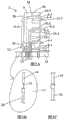
图2A是沿图1中的线II-II截取的视图;FIG. 2A is a view taken along line II-II in FIG. 1;
图2B是图2A所示的接触针的单独视图和分解图,接触针包括与接触针间隔开的延伸针;Figure 2B is an isolated and exploded view of the contact pin shown in Figure 2A, the contact pin including an extension pin spaced apart from the contact pin;
图2C是图2B中的接触针和延伸针接合在一起的视图;Fig. 2C is a view of the contact pin and the extension pin in Fig. 2B joined together;
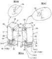
图3A是从图1所示的多端口RJ连接器的两个实例的后方观察到的并排透视图;Figure 3A is a side-by-side perspective view viewed from the rear of two examples of the multi-port RJ connector shown in Figure 1;
图3B是图3A中具有槽的形式的第一互锁结构的端视图;Figure 3B is an end view of the first interlocking structure in the form of a slot in Figure 3A;
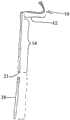
图3C是第二互锁结构的俯视图,该第二互锁结构具有通过支柱与多端口RJ连接器的侧壁间隔开的楔入件或楔形件的形式;3C is a top view of a second interlock structure in the form of a wedge or wedge spaced from the sidewall of the multi-port RJ connector by a post;
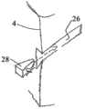
图4是示出将图3C中的第二互锁结构(楔入件)向图3B中的第一互锁结构(槽)插入的单独的透视图;Figure 4 is an isolated perspective view showing insertion of the second interlocking structure (wedge) in Figure 3C into the first interlocking structure (slot) in Figure 3B;
图5是从图1所示类型的多端口RJ连接器的三个实例的后方观察到的透视图,这三个多端口RJ连接器的通过它们的第一互锁结构和第二互锁结构接合在一起;Figure 5 is a perspective view from the rear of three examples of multi-port RJ connectors of the type shown in Figure 1, through their first and second interlocking structures joined together;
图6是沿图3A中的线VI-VI截取的视图;FIG. 6 is a view taken along line VI-VI in FIG. 3A;
图7是图1中的RJ型凹入式连接器的接触件的一个实例的单独视图,该接触件包括RJ接触部分和接触针部分;以及7 is an isolated view of an example of a contact of the RJ type female connector in FIG. 1, the contact including an RJ contact portion and a contact pin portion; and
图8是在PCB的顶部间隔布置的图1所示的多端口RJ连接器的四个实例的正视图,图中的箭头示出多端口RJ连接器的移动,多端口RJ连接器移动到一起并通过它们各自的第一互锁结构和第二互锁结构形成由接合在一起的四个多端口RJ连接器构成的多端口RJ连接器组件。Figure 8 is a front view of four instances of the multi-port RJ connectors shown in Figure 1 spaced apart on the top of the PCB, the arrows in the figure show the movement of the multi-port RJ connectors, the multi-port RJ connectors move together And form a multi-port RJ connector assembly composed of four multi-port RJ connectors joined together by their respective first and second interlocking structures.
具体实施方式Detailed ways
下面将参考附图对本发明进行描述,在附图中,相似的附图标记表示相似的元件。The invention will now be described with reference to the drawings, in which like reference numerals indicate like elements.
参考图1,本发明的多端口RJ连接器2包括连接器主体4,连接器主体4容纳有三个或更多个竖直堆叠的RJ型凹入式连接器6。在图1所示的多端口RJ连接器2中,连接器主体4分别容纳有第一RJ型凹入式连接器6-1、第二RJ型凹入式连接器6-2、第三RJ型凹入式连接器6-3。尽管在此示出和讨论具有三个RJ型凹入式连接器6的多端口RJ连接器2,但是不应该认为本发明局限于此,这是因为可以预见到连接器主体4可以包括四个或更多个竖直堆叠的RJ型凹入式连接器6。Referring to FIG. 1 , the
RJ型凹入式连接器6-1、6-2和6-3分别包括开口8-1、8-2和8-3。开口8-1包括在开口8-1内并排布置的多个接触件10-1(以假想线示出)。类似地,开口8-2包括并排布置的多个接触件10-2而开口8-3包括并排布置的多个接触件10-3。RJ type female connectors 6-1, 6-2 and 6-3 include openings 8-1, 8-2 and 8-3, respectively. The opening 8 - 1 includes a plurality of contacts 10 - 1 (shown in phantom lines) arranged side by side within the opening 8 - 1 . Similarly, the opening 8-2 includes a plurality of contacts 10-2 arranged side by side and the opening 8-3 includes a plurality of contacts 10-3 arranged side by side.
参考图2A至图2C并且继续参考图1,每个接触件10-1包括RJ接触部分12-1和接触针14-1,接触针14-1从接触部分12-1朝向连接器主体4的底部延伸以便插入印刷电路板(PCB)18的通孔16中。Referring to FIGS. 2A to 2C and with continued reference to FIG. 1 , each contact 10-1 includes an RJ contact portion 12-1 and a contact pin 14-1, the contact pin 14-1 extending from the contact portion 12-1 toward the end of the
每个接触件10-2包括接触部分12-2和接触针14-2,接触针14-2从接触部分12-2朝向连接器主体4的底部延伸以便插入PCB 18的通孔16中。最后,每个接触件10-3包括RJ接触部分12-3和接触针14-3,接触针14-3从接触部分12-3朝向连接器主体4的底部延伸以便插入PCB 18的通孔16中。如图2B和图2C所示,任何一个接触针14的远端21可以与延伸针20接合以便在需要时为了有助于所述接触针14插入PCB 18的通孔16内而增加所述接触针14的长度。Each contact 10-2 includes a contact portion 12-2 and a contact pin 14-2 extending from the contact portion 12-2 toward the bottom of the
虽然图1和图2A示出了从连接器主体4中的切口22延伸的接触针14的远端,但是不应该认为本发明局限于此,这是因为能够预见到连接器主体4可以形成为不具有切口22,如图1和图2A中的假想线24所示。Although FIGS. 1 and 2A illustrate the distal ends of contact pins 14 extending from
参考图3A至图3C并继续参考图1和图2A,图3A至图3C示出了两个多端口RJ连接器2的背面的透视图。如从图中可见,每个多端口RJ连接器2在连接器主体4的相反两侧上包括互补式第一互锁结构26和互补式第二互锁结构28。在图示的实施例中,第一互锁结构26的每个实例是槽而第二互锁结构28的每个实例是楔入件。从图3A至图3C中可以看出,连接器主体4的第一互锁结构或第二互锁结构构造为与其他连接器主体4的相应的互补式第二互锁结构或互补式第一互锁结构相配合。尽管在此示出和讨论的第一互锁结构26和第二互锁结构28是槽和楔入件,但是不应该认为本发明局限于此,这是因为使用其他互补式互锁结构也是能够预见到的。Referring to FIGS. 3A-3C with continued reference to FIGS. 1 and 2A , FIGS. 3A-3C show perspective views of the rear of two
图4示出了一个楔入件28和一个槽26的单独视图,其中楔入件28从连接器主体4的背面插入槽26内(如图4中的虚线箭头所示)。FIG. 4 shows a separate view of a wedging
图5示出经由相邻的连接器主体4的互补式第一互锁结构26和互补式第二互锁结构28接合在一起的三个多端口RJ连接器2的后方透视图。FIG. 5 shows a rear perspective view of three
图6示出了沿图3A中的线VI-VI截取的剖视图,其中更清晰地示出了接触针14-1至14-3的阵列。在图示的实施例中,接触针14-1至14-3形成了3×7的接触针14阵列。然而,不应该认为本发明局限于此,这是因为使用其他尺寸的接触针阵列也是能够预见到的。Fig. 6 shows a cross-sectional view taken along line VI-VI in Fig. 3A, more clearly showing the array of contact pins 14-1 to 14-3. In the illustrated embodiment, contact pins 14 - 1 to 14 - 3 form a 3×7 array of contact pins 14 . However, the invention should not be considered so limited, as the use of contact pin arrays of other sizes is also contemplated.
图7示出了包括RJ接触部分12和接触针部分14的单个接触件10的单独视图。如果利用延伸针20来延伸接触针14的长度,则接触针14包括其原始接触针部分加上延伸针20。FIG. 7 shows an isolated view of a
图8示出了在PCB 18的顶部彼此间隔开的四个多端口RJ连接器2/连接器主体4。图8中所示的四个多端口RJ连接器2可以如箭头30所示的那样一起移动并且经由相邻的连接器2上的第一互锁结构26和第二互锁结构28锁定到一起。随后,四个多端口RJ连接器2的接触针以公知的方式插入PCB 18的通孔(在图8中未示出)中并以公知的方式固定(焊接)于该通孔中。FIG. 8 shows four
尤其如图1所示,每个RJ型凹入式连接器包括锁栓缺口32,锁栓缺口32用于在匹配的RJ型凸出式连接器36插入RJ型凹入式连接器6之一的开口8时与该RJ型凸出式连接器36的弹簧锁栓34配合。如图1和图8所示,RJ型凹入式连接器6-1的锁栓缺口32的每个实例朝向相应的连接器主体4的底部。与之对比,多端口RJ连接器2的RJ型凹入式连接器6-2和6-3的锁栓缺口32的每个实例朝向连接器主体4的顶部。一个锁栓缺口面向底部(或顶部)而另两个锁栓缺口面向顶部(或底部)的RJ型凹入式连接器6-1至6-3的布置有助于接触针14-1和14-3(以及任何延伸针20)的紧凑走线。锁栓缺口32的这一布置与所有锁栓缺口32沿同一方向取向(朝向连接器主体4的顶部或连接器主体4的底部)的布置相比还有助于使RJ型凹入式连接器6-1至6-3获得更紧凑的布置以及使连接器主体4获得更低的整体高度。As shown particularly in FIG. 1 , each RJ-type female connector includes a
归因于图1中所示出的每个RJ型凹入式连接器6的锁栓缺口32的取向,RJ型凹入式连接器6-2和6-3的接触部分12设置或取向在开口8-2和8-3的底部,同时RJ型凹入式连接器6-1的RJ接触部分12-1设置或取向在开口8-1的顶部。Due to the orientation of the
优选地,每个多端口RJ连接器2可以选择性地包括位于连接器主体4的顶面、背面和至少一个侧面(优选为两个侧面)的导电且导磁的(接地)遮盖件38。由于多端口RJ连接器2的每个实例与PCB 18接合,因此在连接器主体的底面(在使用时定位成接近PCB18)上可以选择性地不包括导电且导磁的遮盖件38。类似地,在每个RJ型凹入式连接器6的开口8上不包括导电且导磁的遮盖件38。Preferably, each
当分别包括遮盖件38的多个多端口RJ连接器2经由相邻的连接主体4的互补式第一互锁结构26和互补式第二互锁结构28接合在一起(图5)时,这些相邻的连接器2的遮盖件38可以:(1)通过接触(直接地和/或经由联接的互锁结构26和28)在二者之间形成电连接;(2)经由任何适当的装置以公知的方式与PCB 18的地线或平面电接触和机械接触从而与PCB 18的地线或平面电连接;或者(3)由此在多个多端口RJ连接器2的周围以及相邻的所述多端口RJ连接器2之间均形成由所述多个相邻的连接器2的遮盖件38构成的导电且导磁的(接地)遮盖件44(图5)。When a plurality of
作为选择,每个多端口RJ连接器2可以不包括遮盖件38。在该可选实施例中,当多个多端口RJ连接器2经由相邻的连接器主体4的互补式第一互锁结构26和互补式第二互锁结构28接合到一起(图5)时,一个单独的遮盖件44'可以设置成覆盖多个接合的相邻连接器主体4以形成围绕所述多个多端口RJ连接器2的接地遮盖件,该遮盖件44'具有有助于通向所述多个多端口RJ连接器2的RJ型凹入式连接器6的开口8的一个或多个开口。遮盖件44'随后可以经由任何适当的装置以公知的方式与PCB 18的地线或平面电接触和机械接触从而与PCB 18的地线或平面电连接。在本实施例中,遮盖件44'没有任何部分位于相邻的多端口RJ连接器2之间。Alternatively, each
每个RJ型凹入式连接器6可以选择性地包括位于其开口8附近的LED 40(或者任何其他适当种类或类型的灯)。每个LED 40可以以下述方式根据需要与信号或电力接触件10和接地接触件10或遮盖件38连接:该方式允许LED 40经由信号或电力接触件10响应于电力的施加或数据的传输而发光。Each RJ-type female connector 6 may optionally include an LED 40 (or any other suitable kind or type of light) located adjacent its opening 8. Each
RJ型凹入式连接器6-1至6-3中的一个或多个或全部可以选择性地在多端口RJ连接器2的主体4内包括一个或多个一体化磁性部件42(图1)。每个一体化磁性部件可以是绕线部件,绕线部件例如但不限于绕线电感器。关于可包括一体化磁性部件42的其他装置的详细描述可参见US 8,177,585和US 8,033,871,这两篇专利以引用的方式并入本文。在本领域普通技术人员认为适当和/或期望的情况下,可将每个一体化磁性部件与一个或多个接触件10连接。One or more or all of the RJ-type female connectors 6-1 to 6-3 may optionally include one or more integral
已参考附图对本发明进行了描述。显然,在阅读和理解上述详细说明的基础上,本领域技术人员可以进行修改和变型。本发明应解释为包括落入所附权利要求书及其等同内容所限定的范围以内的所有修改与变型。The present invention has been described with reference to the accompanying drawings. Obviously, those skilled in the art will make modifications and alterations upon reading and understanding the above detailed description. The present invention should be construed as including all modifications and variations within the scope defined by the appended claims and their equivalents.
本申请要求2011年10月24日提交的美国临时专利申请No.61/628,074的优先权,该申请的全部内容以引用的方式并入本文。This application claims priority to US Provisional Patent Application No. 61/628,074, filed October 24, 2011, which is hereby incorporated by reference in its entirety.
Claims (13)
Translated fromChineseApplications Claiming Priority (4)
| Application Number | Priority Date | Filing Date | Title |
|---|---|---|---|
| US201161628074P | 2011-10-24 | 2011-10-24 | |
| US61/628,074 | 2011-10-24 | ||
| US13/654,762 | 2012-10-18 | ||
| US13/654,762US20130102195A1 (en) | 2011-10-24 | 2012-10-18 | Multiport RJ Stack Connector With Interlocking Mechanism to Attach to Additional Multiport Stack |
Publications (1)
| Publication Number | Publication Date |
|---|---|
| CN103066450Atrue CN103066450A (en) | 2013-04-24 |
Family
ID=48108965
Family Applications (1)
| Application Number | Title | Priority Date | Filing Date |
|---|---|---|---|
| CN2012104098832APendingCN103066450A (en) | 2011-10-24 | 2012-10-24 | Multiport RJ Stacking Connectors with Interlock Mechanism |
Country Status (1)
| Country | Link |
|---|---|
| CN (1) | CN103066450A (en) |
Citations (4)
| Publication number | Priority date | Publication date | Assignee | Title |
|---|---|---|---|---|
| US6425781B1 (en)* | 1999-01-28 | 2002-07-30 | Bel-Fuse, Inc. | RJ jack with integrated interface magnetics |
| CN1465121A (en)* | 2000-09-17 | 2003-12-31 | 贝尔费斯股份有限公司 | High density rj connector assembly |
| CN101589511A (en)* | 2006-10-23 | 2009-11-25 | 阿兰·L·波克拉斯 | Multi-functional RJ connector with internal cavity of split housing opening |
| US7786009B2 (en)* | 2004-06-29 | 2010-08-31 | Pulse Engineering, Inc. | Universal connector assembly and method of manufacturing |
- 2012
- 2012-10-24CNCN2012104098832Apatent/CN103066450A/enactivePending
Patent Citations (5)
| Publication number | Priority date | Publication date | Assignee | Title |
|---|---|---|---|---|
| US6425781B1 (en)* | 1999-01-28 | 2002-07-30 | Bel-Fuse, Inc. | RJ jack with integrated interface magnetics |
| CN1465121A (en)* | 2000-09-17 | 2003-12-31 | 贝尔费斯股份有限公司 | High density rj connector assembly |
| US7786009B2 (en)* | 2004-06-29 | 2010-08-31 | Pulse Engineering, Inc. | Universal connector assembly and method of manufacturing |
| CN101589511A (en)* | 2006-10-23 | 2009-11-25 | 阿兰·L·波克拉斯 | Multi-functional RJ connector with internal cavity of split housing opening |
| US8033871B2 (en)* | 2006-10-23 | 2011-10-11 | Pocrass Alan L | Multiple function RJ connector with split internal housing opening cavity |
Similar Documents
| Publication | Publication Date | Title |
|---|---|---|
| CN100416939C (en) | Stackable Electrical Connectors | |
| US6099349A (en) | Dual multiport RJ connector arrangement | |
| CN102405564B (en) | Vertical Connectors for Printed Circuit Boards | |
| US7121898B2 (en) | Shielding configuration for a multi-port jack assembly | |
| AU2007291879B2 (en) | Adapter and plug-in connection system | |
| CN2766392Y (en) | Electric connector | |
| CN101710661B (en) | Modular electrical connector with opposing contact support members | |
| CN103066425B (en) | Electric coupler component | |
| US9246276B2 (en) | Electrical connector having a shielding member disposed between two magnetic modules | |
| US8070512B2 (en) | Stacked USB 3.0 connector having a length equal to that of stacked USB 2.0 connector | |
| CN1211348A (en) | Shielded electrical connector | |
| JP2019515477A (en) | High density receptacle | |
| CN105098516B (en) | Mezzanine Socket Connector | |
| US20050255746A1 (en) | Connector assembly | |
| CN103296537A (en) | Electric coupler and electric coupler assembly | |
| US6659809B2 (en) | Receptacle connector assembly with keying devices | |
| US6736680B2 (en) | Modular jack assembly for ethernet applications | |
| EP2224546B1 (en) | Cassette having interchangeable rear mating connectors | |
| US9089065B2 (en) | Electrical connector having a connector standoff | |
| US20130102195A1 (en) | Multiport RJ Stack Connector With Interlocking Mechanism to Attach to Additional Multiport Stack | |
| CN103066450A (en) | Multiport RJ Stacking Connectors with Interlock Mechanism | |
| US8465319B2 (en) | Connector system | |
| JP2006269107A (en) | connector | |
| CN116154514A (en) | Connector and connector assembly | |
| TWM379228U (en) | Electronic connector |
Legal Events
| Date | Code | Title | Description |
|---|---|---|---|
| C06 | Publication | ||
| PB01 | Publication | ||
| C10 | Entry into substantive examination | ||
| SE01 | Entry into force of request for substantive examination | ||
| C02 | Deemed withdrawal of patent application after publication (patent law 2001) | ||
| WD01 | Invention patent application deemed withdrawn after publication | Application publication date:20130424 |