CN103064182A - Image forming apparatus - Google Patents
Image forming apparatusDownload PDFInfo
- Publication number
- CN103064182A CN103064182ACN2012105683867ACN201210568386ACN103064182ACN 103064182 ACN103064182 ACN 103064182ACN 2012105683867 ACN2012105683867 ACN 2012105683867ACN 201210568386 ACN201210568386 ACN 201210568386ACN 103064182 ACN103064182 ACN 103064182A
- Authority
- CN
- China
- Prior art keywords
- movable platen
- movable plate
- axle
- image processing
- processing system
- Prior art date
- Legal status (The legal status is an assumption and is not a legal conclusion. Google has not performed a legal analysis and makes no representation as to the accuracy of the status listed.)
- Granted
Links
- 238000006073displacement reactionMethods0.000claimsdescription64
- 239000000758substrateSubstances0.000claimsdescription23
- 229910004298SiO 2Inorganic materials0.000claimsdescription18
- 238000005452bendingMethods0.000claimsdescription16
- 230000000116mitigating effectEffects0.000claims10
- 238000002347injectionMethods0.000claims7
- 239000007924injectionSubstances0.000claims7
- 230000003760hair shineEffects0.000claims1
- 230000003287optical effectEffects0.000description123
- 238000000034methodMethods0.000description21
- 238000010586diagramMethods0.000description12
- 230000000694effectsEffects0.000description12
- 238000005530etchingMethods0.000description12
- 238000004519manufacturing processMethods0.000description8
- 239000000463materialSubstances0.000description6
- 238000000926separation methodMethods0.000description5
- 238000005304joiningMethods0.000description4
- 229910052751metalInorganic materials0.000description4
- 239000002184metalSubstances0.000description4
- KRHYYFGTRYWZRS-UHFFFAOYSA-NFluoraneChemical compoundFKRHYYFGTRYWZRS-UHFFFAOYSA-N0.000description3
- 230000005540biological transmissionEffects0.000description3
- 239000003086colorantSubstances0.000description3
- 230000007246mechanismEffects0.000description3
- -1polyethylenePolymers0.000description3
- 238000004544sputter depositionMethods0.000description3
- XEEYBQQBJWHFJM-UHFFFAOYSA-NIronChemical compound[Fe]XEEYBQQBJWHFJM-UHFFFAOYSA-N0.000description2
- VYPSYNLAJGMNEJ-UHFFFAOYSA-NSilicium dioxideChemical compoundO=[Si]=OVYPSYNLAJGMNEJ-UHFFFAOYSA-N0.000description2
- XUIMIQQOPSSXEZ-UHFFFAOYSA-NSiliconChemical compound[Si]XUIMIQQOPSSXEZ-UHFFFAOYSA-N0.000description2
- 239000000853adhesiveSubstances0.000description2
- 230000001070adhesive effectEffects0.000description2
- 230000008859changeEffects0.000description2
- 230000008878couplingEffects0.000description2
- 238000010168coupling processMethods0.000description2
- 238000005859coupling reactionMethods0.000description2
- 230000006378damageEffects0.000description2
- 238000010030laminatingMethods0.000description2
- 238000001020plasma etchingMethods0.000description2
- 238000007747platingMethods0.000description2
- 230000004043responsivenessEffects0.000description2
- 239000010703siliconSubstances0.000description2
- 229910052710siliconInorganic materials0.000description2
- 238000001039wet etchingMethods0.000description2
- 239000004925Acrylic resinSubstances0.000description1
- 229920000178Acrylic resinPolymers0.000description1
- 239000004952PolyamideSubstances0.000description1
- 239000004698PolyethyleneSubstances0.000description1
- 239000004743PolypropyleneSubstances0.000description1
- 239000004793PolystyreneSubstances0.000description1
- BQCADISMDOOEFD-UHFFFAOYSA-NSilverChemical compound[Ag]BQCADISMDOOEFD-UHFFFAOYSA-N0.000description1
- 230000002159abnormal effectEffects0.000description1
- 229920000122acrylonitrile butadiene styrenePolymers0.000description1
- 230000009471actionEffects0.000description1
- 229910045601alloyInorganic materials0.000description1
- 239000000956alloySubstances0.000description1
- 229910000828alnicoInorganic materials0.000description1
- 229910052782aluminiumInorganic materials0.000description1
- XAGFODPZIPBFFR-UHFFFAOYSA-NaluminiumChemical compound[Al]XAGFODPZIPBFFR-UHFFFAOYSA-N0.000description1
- 230000015572biosynthetic processEffects0.000description1
- 238000003486chemical etchingMethods0.000description1
- 229910052681coesiteInorganic materials0.000description1
- 229920001577copolymerPolymers0.000description1
- 229910052906cristobaliteInorganic materials0.000description1
- 238000001312dry etchingMethods0.000description1
- 238000007772electroless platingMethods0.000description1
- 238000010894electron beam technologyMethods0.000description1
- 238000009713electroplatingMethods0.000description1
- 239000003822epoxy resinSubstances0.000description1
- 239000011888foilSubstances0.000description1
- 239000011521glassSubstances0.000description1
- PCHJSUWPFVWCPO-UHFFFAOYSA-NgoldChemical compound[Au]PCHJSUWPFVWCPO-UHFFFAOYSA-N0.000description1
- 229910052737goldInorganic materials0.000description1
- 239000010931goldSubstances0.000description1
- 229910000040hydrogen fluorideInorganic materials0.000description1
- 238000009434installationMethods0.000description1
- 238000007733ion platingMethods0.000description1
- 229910052742ironInorganic materials0.000description1
- 239000000696magnetic materialSubstances0.000description1
- 239000000203mixtureSubstances0.000description1
- 229910001172neodymium magnetInorganic materials0.000description1
- 238000001579optical reflectometryMethods0.000description1
- 239000003973paintSubstances0.000description1
- 230000000704physical effectEffects0.000description1
- 239000011295pitchSubstances0.000description1
- 229920002647polyamidePolymers0.000description1
- 229920000647polyepoxidePolymers0.000description1
- 229920000573polyethylenePolymers0.000description1
- 229920000642polymerPolymers0.000description1
- 229920001155polypropylenePolymers0.000description1
- 229920002223polystyrenePolymers0.000description1
- 229920000915polyvinyl chloridePolymers0.000description1
- 239000004800polyvinyl chlorideSubstances0.000description1
- 229920005989resinPolymers0.000description1
- 239000011347resinSubstances0.000description1
- 229910000938samarium–cobalt magnetInorganic materials0.000description1
- 239000000377silicon dioxideSubstances0.000description1
- 235000012239silicon dioxideNutrition0.000description1
- 229920002050silicone resinPolymers0.000description1
- 229910052709silverInorganic materials0.000description1
- 239000004332silverSubstances0.000description1
- 229910052682stishoviteInorganic materials0.000description1
- 230000009466transformationEffects0.000description1
- 229910052905tridymiteInorganic materials0.000description1
- 238000001771vacuum depositionMethods0.000description1
- 238000007740vapor depositionMethods0.000description1
- 229910000859α-FeInorganic materials0.000description1
Images


Classifications
- B—PERFORMING OPERATIONS; TRANSPORTING
- B41—PRINTING; LINING MACHINES; TYPEWRITERS; STAMPS
- B41J—TYPEWRITERS; SELECTIVE PRINTING MECHANISMS, i.e. MECHANISMS PRINTING OTHERWISE THAN FROM A FORME; CORRECTION OF TYPOGRAPHICAL ERRORS
- B41J2/00—Typewriters or selective printing mechanisms characterised by the printing or marking process for which they are designed
- B41J2/435—Typewriters or selective printing mechanisms characterised by the printing or marking process for which they are designed characterised by selective application of radiation to a printing material or impression-transfer material
- B41J2/47—Typewriters or selective printing mechanisms characterised by the printing or marking process for which they are designed characterised by selective application of radiation to a printing material or impression-transfer material using the combination of scanning and modulation of light
- B41J2/471—Typewriters or selective printing mechanisms characterised by the printing or marking process for which they are designed characterised by selective application of radiation to a printing material or impression-transfer material using the combination of scanning and modulation of light using dot sequential main scanning by means of a light deflector, e.g. a rotating polygonal mirror
- B41J2/473—Typewriters or selective printing mechanisms characterised by the printing or marking process for which they are designed characterised by selective application of radiation to a printing material or impression-transfer material using the combination of scanning and modulation of light using dot sequential main scanning by means of a light deflector, e.g. a rotating polygonal mirror using multiple light beams, wavelengths or colours
- G—PHYSICS
- G02—OPTICS
- G02B—OPTICAL ELEMENTS, SYSTEMS OR APPARATUS
- G02B26/00—Optical devices or arrangements for the control of light using movable or deformable optical elements
- G02B26/08—Optical devices or arrangements for the control of light using movable or deformable optical elements for controlling the direction of light
- G02B26/0816—Optical devices or arrangements for the control of light using movable or deformable optical elements for controlling the direction of light by means of one or more reflecting elements
- G02B26/0833—Optical devices or arrangements for the control of light using movable or deformable optical elements for controlling the direction of light by means of one or more reflecting elements the reflecting element being a micromechanical device, e.g. a MEMS mirror, DMD
- G02B26/085—Optical devices or arrangements for the control of light using movable or deformable optical elements for controlling the direction of light by means of one or more reflecting elements the reflecting element being a micromechanical device, e.g. a MEMS mirror, DMD the reflecting means being moved or deformed by electromagnetic means
- G—PHYSICS
- G02—OPTICS
- G02B—OPTICAL ELEMENTS, SYSTEMS OR APPARATUS
- G02B26/00—Optical devices or arrangements for the control of light using movable or deformable optical elements
- G02B26/08—Optical devices or arrangements for the control of light using movable or deformable optical elements for controlling the direction of light
- G02B26/10—Scanning systems
- G02B26/101—Scanning systems with both horizontal and vertical deflecting means, e.g. raster or XY scanners
Landscapes
- Physics & Mathematics (AREA)
- General Physics & Mathematics (AREA)
- Optics & Photonics (AREA)
- Electromagnetism (AREA)
- Mechanical Optical Scanning Systems (AREA)
- Mechanical Light Control Or Optical Switches (AREA)
- Micromachines (AREA)
- Exposure Or Original Feeding In Electrophotography (AREA)
- Facsimile Scanning Arrangements (AREA)
Abstract
Description
Translated fromChinese本申请是申请日为2011年02月22日、申请号为201110043790.8、发明名称为“图像形成装置”的发明申请的分案申请。This application is a divisional application of an invention application with a filing date of February 22, 2011, an application number of 201110043790.8, and an invention title of "image forming device".
技术领域technical field
本发明涉及图像形成装置。The present invention relates to an image forming apparatus.
背景技术Background technique
例如,作为在激光打印机等中通过光扫描进行描绘的光扫描仪,公知有使用由扭转振子构成的致动器的光扫描仪(例如参照专利文献1)。For example, an optical scanner using an actuator composed of a torsional vibrator is known as an optical scanner that performs drawing by optical scanning in a laser printer or the like (for example, refer to Patent Document 1).
在专利文献1中公开了具有绝缘基板和扫描仪主体的致动器,在所述绝缘基板设置有一对永磁铁,所述扫描仪主体由绝缘基板支承为位于一对永磁铁之间。并且,扫描仪主体具有框状的支承部、设置在支承部的内侧的框状的外侧可动板、以及设置在外侧可动板的内侧的内侧可动板(反射镜)。并且,外侧可动板经由在X轴方向延伸的一对第一扭转杆与支承部连结,内侧可动板经由在与X轴方向正交的Y轴方向延伸的第二扭转杆与外侧可动板连结。并且,在外侧可动板和内侧可动板分别设置有线圈。
在这种结构的致动器中,通过使借助通电从各线圈产生的磁场与在一对永磁铁之间产生的磁场发挥作用,外侧可动板与内侧可动板一起以第一扭转杆作为中心轴绕X轴转动,内侧可动板以第二扭转杆作为中心轴绕Y轴转动。这样,在专利文献1的致动器中,通过使内侧可动板二维地转动,能够二维地扫描由内侧可动板反射的光。这种结构在利用1个光扫描仪二维地扫描光的方面是有效的。In the actuator with such a structure, the outer movable plate and the inner movable plate use the first torsion bar as the first torsion bar by causing the magnetic field generated from each coil and the magnetic field generated between the pair of permanent magnets to act. The central axis rotates around the X axis, and the inner movable plate rotates around the Y axis with the second torsion bar as the central axis. In this manner, in the actuator of
然而,在专利文献1的致动器中,由于内侧可动板的转动角存在界限,因此难以增大能够扫描光的区域。为了使用专利文献1的致动器而将光扫描区域设定得大,例如考虑延长光扫描区域与致动器之间的间隔距离,但是,由此,人等障碍物容易进入光扫描区域与致动器之间,光被上述侵入物遮挡的可能性高,并且会产生设置条件受限的问题。However, in the actuator of
专利文献1:日本特开2005-181395号公报Patent Document 1: Japanese Patent Laid-Open No. 2005-181395
发明内容Contents of the invention
本发明的目的在于提供一种即便设置在光扫描区域的附近也能够确保大的光扫描区域的图像形成装置。An object of the present invention is to provide an image forming apparatus capable of securing a large light scanning area even if it is installed near the light scanning area.
这种目的通过下述的本发明达成。This object is achieved by the present invention described below.
本发明的图像形成装置的特征在于,The image forming apparatus of the present invention is characterized in that
上述图像形成装置具有:The image forming apparatus described above has:
光射出部,该光射出部射出光;a light emitting part that emits light;
光扫描仪,该光扫描仪具有用于反射从上述光射出部射出的光的光反射部,使该光反射部分别绕相互正交的第一轴和第二轴转动,从而分别绕上述第一轴和上述第二轴扫描由上述光反射部反射的上述光;以及An optical scanner, the optical scanner has a light reflecting part for reflecting the light emitted from the light emitting part, and the light reflecting part is respectively rotated around a first axis and a second axis orthogonal to each other, so as to respectively rotate around the above-mentioned first axis scanning the light reflected by the light reflection part on one axis and the second axis; and
驱动构件,使上述第一轴和上述第二轴的交点与上述光射出部之间的相对位置关系保持恒定,并使上述光扫描仪绕预定的轴线转动,a driving member for maintaining a constant relative positional relationship between the intersection of the first axis and the second axis and the light emitting portion, and rotating the optical scanner around a predetermined axis,
上述光扫描仪具有:The above optical scanner has:
可动板,该可动板具备光反射部;a movable plate having a light reflection portion;
支承部,该支承部支承上述可动板;以及a support portion that supports the above-mentioned movable plate; and
4个连结部,这4个连结部连结上述可动板和上述支承部,4 connecting parts, these 4 connecting parts connect the above-mentioned movable plate and the above-mentioned supporting part,
在上述可动板的俯视图中,上述4个连结部在上述可动板的外周沿着周方向以90度间隔设置,In the plan view of the above-mentioned movable plate, the above-mentioned four connecting parts are arranged at intervals of 90 degrees along the circumferential direction on the outer periphery of the above-mentioned movable plate,
各上述连结部具有:Each of the above connecting parts has:
驱动部,该驱动部与上述可动板离开配置,且能够相对于上述支承部转动;以及a driving part, which is arranged away from the movable plate and is rotatable relative to the supporting part; and
轴部,该轴部连结上述可动板和上述驱动部,a shaft portion connecting the movable plate and the driving portion,
各上述连结部的上述轴部构成为:通过上述驱动部的转动,各上述连接部的上述轴部在与上述可动板离开的方向的中途在上述可动板的厚度方向弯折变形,The shaft portion of each of the connecting portions is configured to be bent and deformed in the thickness direction of the movable plate in the middle of a direction away from the movable plate by the rotation of the driving portion,
通过使各上述轴部独立地进行上述弯折变形,上述可动板绕上述第一轴和上述第二轴中的各轴转动。The movable plate rotates about each of the first axis and the second axis by independently performing the bending deformation on each of the shaft portions.
由此,能够提供一种即便设置在光扫描区域的附近也能够确保大的光扫描区域的图像形成装置。Accordingly, it is possible to provide an image forming apparatus capable of securing a large light scanning area even if it is installed near the light scanning area.
在本发明的图像形成装置中,优选上述光扫描仪通过依次形成线段的矢量扫描来对上述光进行扫描,上述线段是连结由上述光反射部反射的光所照射的显示面上的不同的2点之间的线段。In the image forming apparatus according to the present invention, it is preferable that the optical scanner scans the light by vector scanning that sequentially forms line segments connecting two different display surfaces irradiated by the light reflected by the light reflection section. The line segment between the points.
根据这种扫描方法(矢量扫描),能够仅对想要照射光的区域扫描光,因此能够高效地显示图像。According to such a scanning method (vector scanning), it is possible to scan light only on an area to be irradiated with light, and thus it is possible to efficiently display an image.
在本发明的图像形成装置中,优选上述图像形成装置具有支承部,上述支承部在维持上述光射出部和上述光扫描仪相互的相对位置关系的状态下支承上述光射出部和上述光扫描仪,In the image forming apparatus according to the present invention, it is preferable that the image forming apparatus includes a supporting portion that supports the light emitting portion and the optical scanner while maintaining the relative positional relationship between the light emitting portion and the optical scanner. ,
上述驱动构件构成为能够使上述光射出部和上述光扫描仪与上述支承部一起转动。The driving means is configured to be able to rotate the light emitting part and the optical scanner together with the supporting part.
由此,无需进行光射出部和光扫描仪的对准调整就能够变更光的扫描区域(显示图像的区域)。This makes it possible to change the light scanning area (area where an image is displayed) without adjusting the alignment between the light emitting unit and the optical scanner.
在本发明的图像形成装置中,优选上述驱动构件具备电动机。In the image forming apparatus of the present invention, it is preferable that the driving means includes a motor.
由此,能够比较简单且廉价地形成图像形成装置。As a result, the image forming apparatus can be formed relatively simply and inexpensively.
在本发明的实施方式中,优选当将在上述可动板的俯视图中正交的2轴设为X轴和Y轴时,In the embodiment of the present invention, it is preferable that when two axes orthogonal to each other in a plan view of the movable plate are referred to as the X axis and the Y axis,
上述4个连结部具有:隔着上述可动板在X轴方向对置的第一连结部和第二连结部;以及隔着上述可动板在Y轴方向对置的第三连结部和第四连结部,The four connecting parts include: a first connecting part and a second connecting part opposed in the X-axis direction across the movable plate; and a third connecting part and a second connecting part opposed in the Y-axis direction across the movable plate. four links,
上述第一连结部和上述第二连结部分别具有:上述驱动部,该驱动部与上述可动板在X轴方向离开配置;作为上述轴部的第一轴部,该第一轴部连结上述可动板和上述驱动部、且沿X轴方向延伸;以及第二轴部,该第二轴部连结上述驱动部和上述扫描仪支承部、且沿Y轴方向延伸,The first connecting portion and the second connecting portion each have: the driving portion disposed away from the movable plate in the X-axis direction; a first shaft portion serving as the shaft portion connected to the a movable plate and the driving unit extending in the X-axis direction; and a second shaft connecting the driving unit and the scanner supporting unit and extending in the Y-axis direction,
上述第三连结部和上述第四连结部分别具有:上述驱动部,该驱动部与上述可动板在Y轴方向离开配置;作为上述轴部的第一轴部,该第一轴部连结上述可动板和上述驱动部、且沿Y轴方向延伸;以及第二轴部,该第二轴部连结上述驱动部和上述扫描仪支承部、且沿X轴方向延伸。The third connecting portion and the fourth connecting portion each have: the driving portion disposed away from the movable plate in the Y-axis direction; a first shaft portion serving as the shaft portion connected to the a movable plate and the drive unit extending in the Y-axis direction; and a second shaft linking the drive unit and the scanner support unit and extending in the X-axis direction.
由此,能够以稳定的状态支承可动板。并且,能够使可动板独立地进行绕相互正交的2个轴的各轴的转动。因此,形成为适用于矢量扫描的光扫描仪。Thereby, the movable panel can be supported in a stable state. In addition, the movable plate can be independently rotated around two axes that are perpendicular to each other. Therefore, it is an optical scanner suitable for vector scanning.
在本发明的图像形成装置中,优选当将与上述X轴和上述Y轴正交的轴设为Z轴时,In the image forming apparatus of the present invention, it is preferable that when an axis perpendicular to the above-mentioned X-axis and the above-mentioned Y-axis is referred to as the Z-axis,
上述4个连结部中的上述第一轴部分别能够形成为以下两种变形:The above-mentioned first shaft parts in the above-mentioned four connecting parts can be formed into the following two deformations respectively:
以形成朝Z轴方向的一方侧凸出的V字状的方式弯折的第一变形;以及以形成朝Z轴方向的另一方侧凸出的V字状的方式弯折的第二变形。A first deformation bent so as to form a V-shape projecting toward one side in the Z-axis direction; and a second deformation bent so as to form a V-shape projecting toward the other side in the Z-axis direction.
通过以这种方式使各第一轴部弯折,能够高效地使可动板变位。By bending the first shaft portions in this way, the movable plate can be efficiently displaced.
在本发明的图像形成装置中,优选通过交替地反复形成以下两种状态,使上述可动板绕上述Y轴转动,上述两种状态为:使上述第一连结部的上述第一轴部进行上述第一变形,同时使上述第二连结部的上述第一轴部进行第二变形的状态;以及使上述第一连结部的上述第一轴部进行上述第二变形,同时使上述第二连结部的上述第一轴部进行上述第一变形的状态,In the image forming apparatus according to the present invention, it is preferable that the movable plate is rotated about the Y-axis by alternately repeating the following two states: the first shaft portion of the first coupling portion is rotated. A state in which the first deformation is performed while the first shaft portion of the second connection portion undergoes the second deformation; and the first shaft portion of the first connection portion is subjected to the second deformation while the second connection The state where the above-mentioned first shaft portion of the portion undergoes the above-mentioned first deformation,
通过交替地反复形成以下两种状态,使上述可动板绕上述X轴转动,上述两种状态为:使上述第三连结部的上述第一轴部进行上述第一变形,同时使上述第四连结部的上述第一轴部进行上述第二变形的状态;以及使上述第三连结部的上述第一轴部进行上述第二变形,同时使上述第四连结部的上述第一轴部进行上述第一变形的状态。The movable plate is rotated about the X-axis by alternately repeating the following two states: the first shaft portion of the third coupling portion undergoes the first deformation, and the fourth A state in which the first shaft portion of the connecting portion undergoes the second deformation; and the first shaft portion of the third connecting portion undergoes the second deformation while simultaneously causing the first shaft portion of the fourth connecting portion The state of the first deformation.
由此,能够使可动板顺畅地转动。Thereby, the movable plate can be rotated smoothly.
在本发明的图像形成装置中,优选上述4个连结部的上述第一轴部分别具有:应力缓和部,该应力缓和部设置在上述可动板与上述驱动部之间;可动板侧轴部,该可动板侧轴部连结上述应力缓和部与上述可动板;以及驱动部侧轴部,该驱动部侧轴部连结上述应力缓和部与上述驱动部,上述4个连结部的第一轴部在上述应力缓和部弯折。In the image forming apparatus according to the present invention, it is preferable that each of the first shaft portions of the four connecting portions includes: a stress relieving portion provided between the movable plate and the driving portion; part, the movable plate side shaft part connects the above-mentioned stress relieving part and the above-mentioned movable plate; The one shaft portion is bent at the stress relaxation portion.
由此,能够利用应力缓和部缓和可动板侧轴部受到的应力,能够防止或者抑制应力朝驱动部侧轴部传递。Thereby, the stress received by the movable plate side shaft portion can be relieved by the stress relieving portion, and transmission of the stress to the driving portion side shaft portion can be prevented or suppressed.
在本发明的图像形成装置中,优选上述4个连结部的上述可动板侧轴部分别绕该可动板侧轴部的中心轴扭转变形。In the image forming apparatus according to the present invention, it is preferable that the movable plate-side shaft portions of the four connecting portions are twisted and deformed around the central axes of the movable plate-side shaft portions.
由此,通过另一对连结部的可动板侧轴部扭转变形,能够允许可动板以4个连结部中的对置的一对连结部为轴转动。因此,能够使可动板绕相互正交的2个轴的各轴顺畅地转动。As a result, the movable plate can be allowed to rotate about the pair of opposing connecting portions among the four connecting portions by twisting and deforming the movable plate-side shaft portion of the other pair of connecting portions. Therefore, it is possible to smoothly rotate the movable plate around each of the two axes perpendicular to each other.
在本发明的图像形成装置中,优选上述4个连结部的上述驱动部侧轴部分别并不变形。In the image forming apparatus of the present invention, it is preferable that the drive unit side shaft portions of the four connecting portions are not deformed.
由此,能够高效地将通过驱动部的转动产生的应力用于可动板的转动。因此,能够使可动板以大的转动角度、且节省电力地变位。Thereby, the stress generated by the rotation of the driving portion can be efficiently used for the rotation of the movable plate. Therefore, it is possible to displace the movable plate at a large rotation angle while saving power.
在本发明的图像形成装置中,优选上述4个连结部的上述应力缓和部分别具有变形部,在上述可动板的俯视图中,该变形部沿着与可动板侧轴部和驱动部侧轴部的延伸方向正交的方向延伸,且绕中心轴扭转变形。In the image forming apparatus of the present invention, it is preferable that each of the stress relieving parts of the four connecting parts has a deformation part, and in a plan view of the movable plate, the deformation part is aligned with the shaft part on the side of the movable plate and the side of the driving part. The shaft portion extends in a direction perpendicular to the direction in which it extends, and is twisted and deformed around the central axis.
由此,通过变形部扭转变形,能够有效地缓和施加于第一轴部的应力。Thereby, the stress applied to the first shaft portion can be effectively relieved by the torsional deformation of the deformation portion.
在本发明的图像形成装置中,优选上述4个连结部的上述应力缓和部分别具有一对上述变形部,In the image forming apparatus of the present invention, it is preferable that each of the stress relieving portions of the four connecting portions has a pair of the deforming portions,
上述一对变形部中的一方的上述变形部与上述可动板侧轴部连结,另一方的上述变形部与上述驱动部侧轴部连结。One of the pair of deforming portions is connected to the movable plate-side shaft portion, and the other deforming portion is connected to the drive portion-side shaft portion.
由此,通过变形部扭转变形,能够有效地缓和施加于第一轴部的应力。Thereby, the stress applied to the first shaft portion can be effectively relieved by the torsional deformation of the deformation portion.
在本发明的图像形成装置中,优选上述4个连结部的上述应力缓和部分别具有非变形部,该非变形部设置在上述一对变形部之间,沿与上述变形部的延伸方向平行的方向延伸,且并不绕中心轴扭转变形。In the image forming apparatus of the present invention, it is preferable that each of the stress relieving portions of the four connecting portions has a non-deformable portion provided between the pair of deformable portions along a direction parallel to the extending direction of the deformable portion. direction, and does not twist around the central axis.
由此,在各连结部中,能够使第一轴部以非变形部为轴弯折。因此,能够简单且可靠地使各连结部的第一轴部弯折,能够使可动板稳定地变位。Accordingly, in each connecting portion, the first shaft portion can be bent about the non-deformable portion as an axis. Therefore, the first shaft portion of each connecting portion can be easily and reliably bent, and the movable plate can be stably displaced.
在本发明的图像形成装置中,优选上述4个连结部中的上述应力缓和部分别具有沿着上述X轴方向和上述Y轴方向交替地延伸而曲折的部位。In the image forming apparatus according to the present invention, it is preferable that each of the stress relieving portions among the four connecting portions has portions extending alternately along the X-axis direction and the Y-axis direction to meander.
由此,能够利用应力缓和部缓和可动板侧轴部受到的应力,能够防止或者抑制应力朝驱动部侧轴部传递。Thereby, the stress received by the movable plate side shaft portion can be relieved by the stress relieving portion, and transmission of the stress to the driving portion side shaft portion can be prevented or suppressed.
在本发明的图像形成装置中,优选上述4个连结部的上述应力缓和部分别具有沿着上述X轴方向延伸的多个延伸部和沿着Y轴方向延伸的多个延伸部,上述多个延伸部分别能够绕中心轴扭转变形且能够弯曲变形。In the image forming apparatus of the present invention, it is preferable that the stress relieving portions of the four connecting portions each have a plurality of extending portions extending in the X-axis direction and a plurality of extending portions extending in the Y-axis direction, and the plurality of The extension parts are respectively capable of twisting deformation around the central axis and capable of bending deformation.
由此,通过各延伸部进行扭转变形和弯曲变形中的至少一方的变形,能够有效地缓和施加于第一轴部的应力。As a result, the stress applied to the first shaft portion can be effectively relaxed by deforming at least one of torsional deformation and bending deformation of each extending portion.
在本发明的图像形成装置中,优选上述4个连结部分别由SOI基板形成,上述SOI基板通过按照顺序层叠第一Si层、SiO2层以及第二Si层而成的SOI基板而形成。In the image forming apparatus of the present invention, it is preferable that each of the four connecting portions is formed of an SOI substrate formed by sequentially laminating a first Si layer, an SiO2 layer, and a second Si layer.
由此,能够简单地形成各连结部。Thereby, each connection part can be formed easily.
在本发明的图像形成装置中,优选上述4个连结部的上述非变形部、驱动部侧轴部以及驱动部分别由上述第一Si层、上述SiO2层以及上述第二Si层构成,上述可动板侧轴部、上述变形部以及上述第二轴部分别由上述第二Si层构成。In the image forming apparatus of the present invention, it is preferable that the non-deformable portion, the driving portion side shaft portion, and the driving portion of the four connecting portions are respectively composed of the first Si layer, theSiO2 layer, and the second Si layer, and the The movable plate side shaft portion, the deformation portion, and the second shaft portion are each formed of the second Si layer.
由此,能够简单地形成各连结部。Thereby, each connection part can be formed easily.
在本发明的图像形成装置中,优选上述图像形成装置具有使上述可动板相对于上述支承部变位的变位构件,In the image forming apparatus according to the present invention, it is preferable that the image forming apparatus includes a displacement member for displacing the movable plate relative to the support portion,
上述变位构件与上述4个连结部对应地设置有4个。Four displacement members are provided corresponding to the four connection parts.
由此,能够独立地控制各连结部的动作。Thereby, it is possible to independently control the operation of each connection part.
在本发明的图像形成装置中,优选上述4个变位构件分别具有:永磁铁,该永磁铁设置于对应的上述驱动部;以及线圈,该线圈用于产生作用于上述永磁铁的磁场。In the image forming apparatus according to the present invention, each of the four displacement members preferably includes a permanent magnet provided in the corresponding driving unit, and a coil for generating a magnetic field acting on the permanent magnet.
由此,变位构件的结构变得简单。并且,由于是电磁驱动,因此能够产生大的力。Thereby, the structure of a displacement member becomes simple. In addition, since it is driven electromagnetically, a large force can be generated.
在本发明的图像形成装置中,优选在上述4个变位构件中,上述永磁铁以两极在上述可动板的厚度方向对置的方式设置,上述线圈以产生与上述可动板的厚度方向正交的方向的磁场的方式设置。In the image forming apparatus according to the present invention, it is preferable that among the four displacement members, the permanent magnets are provided so that their two poles face each other in the thickness direction of the movable plate, and the coils are arranged so as to be aligned with the thickness direction of the movable plate. Orthogonal directions of the magnetic field are set in a manner.
由此,能够使可动板稳定地变位。Thereby, the movable plate can be displaced stably.
在本发明的图像形成装置中,优选上述4个变位构件的上述永磁铁分别贯通上述驱动部而设置。In the image forming apparatus according to the present invention, it is preferable that the permanent magnets of the four displacement members respectively pass through the drive unit.
由此,能够使可动板稳定地变位。Thereby, the movable plate can be displaced stably.
附图说明Description of drawings
图1是示出本发明的图像形成装置的第一实施方式的图。FIG. 1 is a diagram showing a first embodiment of an image forming apparatus of the present invention.
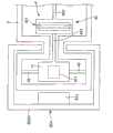
图2是示出图1所示的图像形成装置的概要结构的图。FIG. 2 is a diagram showing a schematic configuration of the image forming apparatus shown in FIG. 1 .
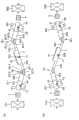
图3是图1所示的图像形成装置所具有的光扫描仪的平面图。3 is a plan view of an optical scanner included in the image forming apparatus shown in FIG. 1 .
图4是图3所示的光扫描仪的剖视图(沿着图3中A-A线的剖视图)。FIG. 4 is a cross-sectional view of the optical scanner shown in FIG. 3 (a cross-sectional view along line AA in FIG. 3 ).
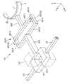
图5是图3所示的光扫描仪所具有的连结部的立体图。FIG. 5 is a perspective view of a connecting portion included in the optical scanner shown in FIG. 3 .
图6是用于说明图3所示的光扫描仪所具有的振动系统的制造方法的剖视图。6 is a cross-sectional view for explaining a method of manufacturing a vibration system included in the optical scanner shown in FIG. 3 .
图7是用于说明图3所示的光扫描仪所具有的振动系统的制造方法的剖视图。7 is a cross-sectional view illustrating a method of manufacturing a vibration system included in the optical scanner shown in FIG. 3 .
图8是用于说明图3所示的光扫描仪所具有的变位构件的图。FIG. 8 is a diagram for explaining a displacement member included in the optical scanner shown in FIG. 3 .
图9是用于说明图3所示的光扫描仪的驱动的图。FIG. 9 is a diagram for explaining driving of the optical scanner shown in FIG. 3 .
图10是用于说明图3所示的光扫描仪的驱动的图。FIG. 10 is a diagram for explaining driving of the optical scanner shown in FIG. 3 .
图11是用于说明图3所示的光扫描仪的驱动的图。FIG. 11 is a diagram for explaining driving of the optical scanner shown in FIG. 3 .
图12是用于说明图3所示的光扫描仪的驱动的图。FIG. 12 is a diagram for explaining driving of the optical scanner shown in FIG. 3 .
图13是示出图1所示的图像形成装置所具有的驱动构件的剖视图。FIG. 13 is a cross-sectional view showing a driving member included in the image forming apparatus shown in FIG. 1 .
图14是用于说明图13所示的驱动构件的驱动的俯视图。Fig. 14 is a plan view for explaining driving of the driving member shown in Fig. 13 .
图15是示出图1所示的图像形成装置的动作的图。FIG. 15 is a diagram showing the operation of the image forming apparatus shown in FIG. 1 .
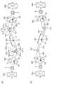
图16是本发明所涉及的第二实施方式的图像形成装置所具有的光扫描仪的平面图。16 is a plan view of an optical scanner included in an image forming apparatus according to a second embodiment of the present invention.
图17是本发明所涉及的第三实施方式的图像形成装置所具有的光扫描仪的平面图。17 is a plan view of an optical scanner included in an image forming apparatus according to a third embodiment of the present invention.
图18是本发明所涉及的第四实施方式的图像形成装置所具有的光扫描仪的立体图。18 is a perspective view of an optical scanner included in an image forming apparatus according to a fourth embodiment of the present invention.
图19是本发明所涉及的第五实施方式的图像形成装置所具有的光扫描仪的剖视图。19 is a cross-sectional view of an optical scanner included in an image forming apparatus according to a fifth embodiment of the present invention.
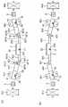
图20是示出本发明的第六实施方式所涉及的图像形成装置所具有的光扫描仪的平面图。20 is a plan view showing an optical scanner included in an image forming apparatus according to a sixth embodiment of the present invention.
图21是图20所示的光扫描仪所具有的连结部的放大立体图。FIG. 21 is an enlarged perspective view of a connecting portion included in the optical scanner shown in FIG. 20 .
图22是示出本发明所涉及的第六实施方式的图像形成装置所具有的光扫描仪的立体图。22 is a perspective view showing an optical scanner included in an image forming apparatus according to a sixth embodiment of the present invention.
标号说明Label description
1…光扫描仪;11…振动系统;12…基座;121…基部;122…框部;2、2D…可动板;21…面;22…光反射部;23D…基部;24D…柱部;25D…光反射板;3…支承部;4、4C、5、6、7…连结部;41、51、61、71…驱动板;42、42C、52、62、72…第一轴部;421、421C、421E、521、521E、621、621E、721、721E…应力缓和部;4211、4212、5211、5212、6211、6212、7211、7212…变形部;4213、4213C、5213、6213、7213…非变形部;4214、4215、5214、5215、6214、6215、7214、7215…连接部;4211E…第一延伸部;4212E…第二延伸部;4213E…第三延伸部;4214E…第四延伸部;4215E…第五延伸部;4216E…第六延伸部;4217E…第七延伸部;422、522、622、722…可动板侧轴部;423、523、623、723…驱动板侧轴部;43、53、63、73…第二轴部;8…变位构件;81、81B…第一变位构件;82…第二变位构件;83…第三变位构件;84…第四变位构件;811、811B、821、831、841…永磁铁;812、812B、822、832、842…线圈;813、813B、823、833、843…电源;85、85A…线圈固定部;851…突出部;852A…主体部;100…图像形成装置;200…光源单元;210r…红色光源装置;210g…绿色光源装置;210b…蓝色光源装置;220r、220g、220b…准直透镜;230r、230g、230b…分色镜(dichroicmirror);300…驱动构件;310…第一齿轮;320…第二齿轮;330…电动机;331…轴部;400…支承部;410…轴部;411…贯通孔;420…轴承;430…安装部;500…SOI基板;510…第一Si层;520…SiO2层;530…第二Si层;M1、M2…SiO2膜;X1~X3、Y1~Y3…转动中心轴;X4、X5、Y4、Y5…中心轴;J1、J2…预定的轴线;S…投影屏;S1、S2…光扫描区域。1... Optical scanner; 11... Vibration system; 12... Base; 121... Base; 122... Frame; 2, 2D... Movable plate; 21... Surface; 22... Light reflection part; Part; 25D...light reflection plate; 3...supporting part; 4, 4C, 5, 6, 7... connecting part; 41, 51, 61, 71... drive plate; 42, 42C, 52, 62, 72... first shaft Part; 421, 421C, 421E, 521, 521E, 621, 621E, 721, 721E... Stress relief part; 4211, 4212, 5211, 5212, 6211, 6212, 7211, 7212... Deformation part; 4213, 4213C, 5213, 6213 , 7213...non-deformable part; 4214, 4215, 5214, 5215, 6214, 6215, 7214, 7215... connecting part; 4211E... first extending part; 4212E... second extending part; 4213E... third extending part; 4214E... first extending part Four extensions; 4215E...fifth extension; 4216E...sixth extension; 4217E...seventh extension; 422, 522, 622, 722... movable plate side shaft; Side shaft part; 43, 53, 63, 73...second shaft part; 8...displacement member; 81, 81B...first displacement member; 82...second displacement member; 83...third displacement member; 84 ...the fourth displacement member; 811, 811B, 821, 831, 841...permanent magnet; 812, 812B, 822, 832, 842...coil; 813, 813B, 823, 833, 843...power supply; 85, 85A...coil fixed 851...protruding part; 852A...main body; 100...image forming device; 200...light source unit; 210r...red light source device; 210g...green light source device; 210b...blue light source device; Lens; 230r, 230g, 230b... dichroic mirror; 300... driving member; 310... first gear; 320... second gear; 330... motor; 331... shaft; 400... supporting part; 410... shaft ;411...Through hole; 420...Bearing; 430...Mounting part; 500...SOI substrate; 510...First Si layer; 520...SiO2 layer; 530...Second Si layer; M1, M2...SiO2 film; X3, Y1~Y3...the central axis of rotation; X4, X5, Y4, Y5...the central axis; J1, J2...the predetermined axis; S...the projection screen; S1, S2...the optical scanning area.
具体实施方式Detailed ways
以下,参照附图对本发明的图像形成装置的优选的实施方式进行说明。Hereinafter, preferred embodiments of the image forming apparatus of the present invention will be described with reference to the drawings.
<第一实施方式><First Embodiment>
首先,对本发明的图像形成装置的第一实施方式进行说明。First, a first embodiment of the image forming apparatus of the present invention will be described.
图1是示出本发明的图像形成装置的第一实施方式的图,图2是示出图1所示的图像形成装置的概要结构的图,图3是图1所示的图像形成装置所具有的光扫描仪的平面图,图4是图3所示的光扫描仪的剖视图(沿着图3中的A-A线的剖视图),图5是图3所示的光扫描仪所具有的连结部的立体图,图6和图7分别是用于说明图3所示的光扫描仪所具有的振动系统的制造方法的图,图8是用于说明图3所示的光扫描仪所具有的变位构件的图,图9是用于说明图3所示的光扫描仪的驱动的图,图10、图11、以及图12分别是用于说明图3所示的光扫描仪的驱动的图,图13是示出图1所示的图像形成装置所具有的驱动构件的剖视图,图14是用于说明图13所示的驱动构件的驱动的俯视图,是示出图1所示的图像形成装置的动作的图。1 is a diagram showing a first embodiment of an image forming apparatus according to the present invention, FIG. 2 is a diagram showing a schematic configuration of the image forming apparatus shown in FIG. 1 , and FIG. There is a plan view of the optical scanner, Fig. 4 is a sectional view of the optical scanner shown in Fig. 3 (a sectional view along the A-A line in Fig. 3), and Fig. 5 is a sectional view of the optical scanner shown in Fig. 3 6 and 7 are views for explaining a method of manufacturing a vibration system included in the optical scanner shown in FIG. 3, and FIG. Figure 9 is a diagram for explaining the driving of the optical scanner shown in Figure 3, and Figure 10, Figure 11, and Figure 12 are respectively used to explain the driving of the optical scanner shown in Figure 3 13 is a cross-sectional view showing the driving member of the image forming apparatus shown in FIG. A diagram of the operation of the image forming apparatus.
另外,以下,为了说明的方便,将图3中的左侧称为“左”、将右侧称为“右”,将图4~图12中的上侧称为“上”、将下侧称为“下”。并且,如图3所示,将相互正交的3轴设为X轴(第一轴)、Y轴(第二轴)以及Z轴,非驱动状态的可动板的面与由X轴和Y轴形成的面一致(平行),可动板的厚度方向与Z轴一致。并且,以下,将与X轴平行的方向称为“X轴方向”、将与Y轴平行的方向称为“Y轴方向”、将与Z轴平行的方向称为“Z轴方向”。In addition, hereinafter, for convenience of description, the left side in FIG. 3 is referred to as “left”, the right side is referred to as “right”, the upper side in FIGS. Called "down". In addition, as shown in FIG. 3, let the three mutually orthogonal axes be the X axis (first axis), the Y axis (second axis), and the Z axis, and the surface of the movable plate in the non-driven state is aligned with the X axis and the The plane formed by the Y axis coincides (parallel), and the thickness direction of the movable plate coincides with the Z axis. In addition, hereinafter, the direction parallel to the X-axis is referred to as "X-axis direction", the direction parallel to the Y-axis is referred to as "Y-axis direction", and the direction parallel to the Z-axis is referred to as "Z-axis direction".
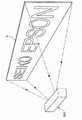
图1所示的图像形成装置100例如是用于在设置于大楼等建筑物内或者室外的投影屏(显示对象物)S显示静态图像或动态图像等预定的图像的装置。如图2所示,这种图像形成装置100具有:光射出部200,该光射出部200用于射出激光(光);光扫描仪1,该光扫描仪1用于反射从光射出部200射出的光;以及驱动构件300,该驱动构件300用于使光扫描仪1绕预定的轴线转动。The
作为投影屏S的构成材料,并无特殊限定,例如能够举出聚乙烯、聚丙烯、聚氯乙烯、聚苯乙烯、聚酰胺、丙烯类树脂、ABS树脂、氟树脂、环氧树脂、有机硅树脂、或者以上述材料为主的共聚物、混合物、聚合物合金等,能够使用上述材料中的1种或者组合2种以上进行使用。由此,能够提高图像的目视确认性。另外,投影屏S也可以省略,例如直接在建筑物的墙面或者地面显示图像。The material constituting the projection screen S is not particularly limited, and examples thereof include polyethylene, polypropylene, polyvinyl chloride, polystyrene, polyamide, acrylic resin, ABS resin, fluororesin, epoxy resin, and silicone resin. Resins, or copolymers, mixtures, polymer alloys, and the like mainly composed of the above-mentioned materials can be used by using one of the above-mentioned materials or in combination of two or more. Thereby, the visibility of an image can be improved. In addition, the projection screen S can also be omitted, such as directly displaying images on the wall or ground of the building.
以下,依次对图像形成装置的各结构进行详细说明。Hereinafter, each configuration of the image forming apparatus will be described in detail in order.
(光射出部200)(light emitting part 200)
如图2所示,光射出部(光源单元)200具备:各种颜色的激光光源210r、210g、210b;以及与各种颜色的激光光源210r、210g、210b对应地设置的准直透镜2220r、220g、220b和分色镜230r、230g、230b。As shown in FIG. 2 , the light emitting unit (light source unit) 200 includes: laser light sources 210r, 210g, and 210b of various colors; and collimator lenses 2220r, 2220r, and 220g, 220b and dichroic mirrors 230r, 230g, 230b.
各种颜色的激光光源210r、210g、210b分别射出红色、绿色以及蓝色的激光RR、GG、BB。激光RR、GG、BB分别以与从未图示的控制部发送的驱动信号对应地被调制的状态射出,并由作为准直光学元件的准直透镜220r、220g、220b平行化而形成细光束。Laser light sources 210r, 210g, and 210b of respective colors emit red, green, and blue laser light RR, GG, and BB, respectively. The laser beams RR, GG, and BB are respectively emitted in a modulated state corresponding to driving signals sent from a control unit not shown in the figure, and are collimated by collimator lenses 220r, 220g, and 220b as collimator optical elements to form thin beams. .
分色镜230r、230g、230b分别具有反射红色激光RR、绿色激光GG、蓝色激光BB的特性,结合各种颜色的激光RR、GG、BB而射出1条激光LL。The dichroic mirrors 230r, 230g, and 230b have characteristics of reflecting red laser light RR, green laser light GG, and blue laser light BB, respectively, and combine laser light RR, GG, and BB of each color to emit a single laser light LL.
另外,能够代替准直透镜220r、220g、220b使用准直反射镜,在该情况下,也能够形成平行光束的细光束。并且,在从各种颜色的激光光源210r、210g、210b射出平行光束的情况下,能够省略准直透镜220r、220g、220b。进一步,对于激光光源210r、210g、210b,能够更换成产生同样的光束的发光二极管等光源。并且,图2的各种颜色的激光光源210r、210g、210b、准直透镜220r、220g、220b以及分色镜230r、230g、230b的次序只不过是一例,能够在保持各种颜色的组合(红色为激光光源210r、准直透镜220r、分色镜230r,绿色为激光光源210g、准直透镜220g、分色镜230g,蓝色为激光光源210b、准直透镜220b、分色镜230b)的状态下自由地设定顺序。例如,能够按照依次接近光扫描仪1的顺序形成蓝色、红色、绿色的组合。In addition, a collimating mirror can be used instead of the collimating lenses 220r, 220g, and 220b, and in this case, a narrow beam of parallel beams can also be formed. Furthermore, when the laser light sources 210r, 210g, and 210b of each color emit parallel light beams, the collimator lenses 220r, 220g, and 220b can be omitted. Furthermore, the laser light sources 210r, 210g, and 210b can be replaced with light sources such as light emitting diodes that generate similar light beams. Moreover, the order of laser light sources 210r, 210g, 210b, collimator lenses 220r, 220g, 220b, and dichroic mirrors 230r, 230g, 230b of various colors in FIG. Red is laser light source 210r, collimating lens 220r, dichroic mirror 230r, green is laser light source 210g, collimating lens 220g, dichroic mirror 230g, blue is laser light source 210b, collimating lens 220b, dichroic mirror 230b) The order can be freely set in the state. For example, a combination of blue, red, and green can be formed in the order of approaching the
(光扫描仪)(optical scanner)
其次,对光扫描仪1进行说明。Next, the
光扫描仪1是使用光栅扫描(raster scan)、矢量扫描(vector scan)等扫描方法对投影屏S的表面(显示面)扫描从光源单元200射出的激光LL的装置。此处,所谓光栅扫描是指当在水平方向扫描激光LL的同时在垂直方向扫描激光LL的方法,与应当在投影屏S显示的图像无关,一律在显示面的整个区域规则地扫描激光LL。所谓另一方面的矢量扫描是指以依次形成连结投影屏S的表面上的不同的2点的线段的方式进行扫描的方法,根据应当在显示面显示的图像仅在显示面的必要的部位不规则地扫描激光LL。另外,在本实施方式中使用的光扫描仪1能够利用光栅扫描和矢量扫描中的任一种方法扫描激光LL,但是,在结构上优选利用矢量扫描来扫描激光LL。The
如图3和图4所示,光扫描仪1具有:振动系统11,该振动系统11由可动板2、支承部3、以及4个连结部4、5、6、7构成,所述支承部3用于支承可动板2,所述4个连结部4、5、6、7用于连结可动板2和支承部3;基座12,该基座12用于支承振动系统11;以及变位构件8,该变位构件8用于使可动板2变位。以下,依次对光扫描仪1的各结构进行详细说明。另外,将相互正交的3轴设为X轴、Y轴以及Z轴,非驱动状态的可动板的面与由X轴和Y轴形成的面一致(平行),可动板的厚度方向与Z轴一致。并且,以下,将与X轴平行的方向称为“X轴方向”,将与Y轴平行的方向称为“Y轴方向”,将与Z轴平行的方向称为“Z轴方向”。As shown in FIGS. 3 and 4 , the
[振动系统11][vibration system 11]
在本实施方式中,振动系统11通过利用干蚀刻(dry etching)和湿蚀刻(wet etching)等各种蚀刻方法将SOI基板的不需要的部位除去而一体地形成。另外,对于振动系统11的制造方法在后面详细叙述。In the present embodiment, the
支承部3具有支承可动板2的功能。这种支承部3形成为框状,并以包围可动板2的周围的方式设置。另外,作为支承部3的形状,只要能够支承可动板2即可,并无特殊限定,例如,也可以以隔着可动板2在X轴方向或者Y轴方向对置的方式设置有一对。The
可动板2设置在支承部3的内侧。可动板2形成为平板状,且在一方的面(与基座12相反侧的面)21形成有具有光反射性的光反射部22。光反射部22例如通过在面21上借助蒸镀等形成金、银、铝等的金属膜等而得到。The
另外,在本实施方式中,可动板2的俯视形状为圆形,但是,可动板2的俯视形状并无特殊限定,例如也可以是长方形、正方向等多边形,或者是椭圆形等。In addition, in this embodiment, the top view shape of the
这种可动板2借助4个连结部4、5、6、7与支承部3连结。4个连结部4、5、6、7在可动板2的俯视图中沿着可动板2的周方向等间隔地、即以90度间隔配置。Such a
进而,4个连结部4、5、6、7中的连结部4、6隔着可动板2在X轴方向对置、且相对于可动板2对称地形成,连结部5、7隔着可动板2在Y轴方向对置、且相对于可动板2对称地形成。通过利用这种连结部4、5、6、7支承可动板2,能够以稳定的状态支承可动板2。并且,如后所述,能够分别独立地进行可动板2的绕转动中心轴X1的转动和绕转动中心轴Y1的转动。Furthermore, among the four connecting
4个连结部4、5、6、7相互形成为同样的结构。The four
具体地说,连结部(第一连结部)4具有:驱动板(驱动部)41;第一轴部42,该第一轴部42连结驱动板41和可动板2;以及一对第二轴部43,这一对第二轴部43连结驱动板41和支承部3。并且,连结部(第三连结部)5具有:驱动板51;第一轴部52,该第一轴部52连结驱动板51和可动板2;以及一对第二轴部53,这一对第二轴部53连结驱动板51和支承部3。并且,连结部(第二连结部)6具有:驱动板61;第一轴部62,该第一轴部62连结驱动板61和可动板2;以及一对第二轴部63,这一对第二轴部63连结驱动板61和支承部3。并且,连结部(第四连结部)7具有:驱动板71;第一轴部72,该第一轴部72连结驱动板71和可动板2;以及一对第二轴部73,这一对第二轴部73连结驱动板71和支承部3。另外,上述“同样的结构”是指构成连结部的要素相同。因此,外形形状不需要一致。Specifically, the connection part (first connection part) 4 has: a drive plate (drive part) 41; a
通过将各连结部4、5、6、7形成为这种结构,连结部的结构变得简单,并且,如后所述,能够使可动板2顺畅地进行绕转动中心轴X1、Y1的转动等。By forming the connecting
以下,对连结部4、5、6、7进行具体说明,但是,由于连结部4、5、6、7的结构相互同样,因此以连结部4作为代表进行说明,省略对其他的连结部5、6、7的说明。另外,连结部5、7在可动板2的俯视图中配置成相对于连结部4旋转90度后的状态。因此,对于连结部5、7,能够通过将下述的连结部4的说明中的“Y轴方向”改成“X轴方向”、将“X轴方向”改成“Y轴方向”进行说明。Hereinafter, the connecting
如图5所示,一对第二轴部43隔着驱动板41在Y轴方向对置配置,对驱动板41进行双支承。并且,一对第二轴部43分别形成为在Y轴方向延伸的棒状。并且,一对第二轴部43能够绕中心轴扭转变形。这种一对第二轴部43同轴地设置,在一对第二轴部43以该轴(以下也称为“转动中心轴Y2”)为中心扭转变形的同时,驱动板41转动。As shown in FIG. 5 , the pair of
驱动板41在X轴方向相对于可动板2离开设置。并且,如前面所述,驱动板41由一对第二轴部43双支承。在这种驱动板41形成有贯通孔411,永磁铁811插通并固定在该贯通孔中。永磁铁811例如通过嵌合(压入)或者借助粘接剂固定于驱动板41。永磁铁811是变位构件8的结构的一部分,因此在后面进行说明。The
并且,在本实施方式中,驱动板41的俯视形状形成为以Y轴方向作为长边的长方形。通过将驱动板41形成为这种形状,能够确保固定永磁铁811的空间,并且能够抑制驱动板41的宽度(X轴方向的长度)。通过抑制驱动板41的宽度,能够抑制当驱动板41绕转动中心轴Y2转动时产生的惯性矩,驱动板41的响应性提高,能够更高速地转动。并且,当驱动板41的响应性提高时,能够抑制由于驱动板41的转动(特别是转动方向转换的反转时)而产生非本意的振动。因此,能够稳定地驱动光扫描仪1。In addition, in the present embodiment, the
另外,作为驱动板41的俯视形状,并无特殊限定,例如可以是正方形或五边形以上的多边形,也可以是圆形。In addition, the top view shape of the
这种驱动板41借助第一轴部42与可动板2连结。第一轴部42以整体在X轴方向延伸的方式设置。这种第一轴部42具有:应力缓和部421,该应力缓和部421设置在驱动板41与可动板2之间;可动板侧轴部422,该可动板侧轴部422用于连结应力缓和部421和可动板2;以及驱动板侧轴部(驱动部侧轴部)423,该驱动板侧轴部423用于连结应力缓和部421和驱动板41。Such a
可动板侧轴部422和驱动板侧轴部423分别呈在X轴方向延伸的棒状。并且,可动板侧轴部422和驱动板侧轴部423同轴地设置。The movable plate
这两个轴部中的驱动板侧轴部423优选设定成当光扫描仪1的驱动时不会产生大的变形的硬度,更加优选设定成实质上不会变形的硬度。与此相对,可动板侧轴部422能够绕其中心轴扭转变形。这样,第一轴部42具有实质上不变形的硬部分以及位于该硬部分的前端侧的可扭转变形的部位,由此,如后所述,能够使可动板2绕X轴和Y轴的各轴稳定地转动。另外,上述“不变形”是指实质上不会产生朝向Z轴方向的弯折或者弯曲以及绕中心轴的扭转变形。Of these two shafts, the drive plate
这种可动板侧轴部422和驱动板侧轴部423经由应力缓和部421连结。应力缓和部421具有以下功能:作为第一轴部42弯折变形时的节部的功能;以及缓和(吸收)通过可动板侧轴部422的扭转变形产生的扭矩,防止或者抑制上述扭矩传递到驱动板侧轴部423。The movable plate
如图5所示,应力缓和部421具有:一对变形部4211、4212;非变形部4213,该非变形部4213设置在一对变形部4211、4212之间;用于将变形部4211连接于非变形部4213的一对连接部4214;以及用于将变形部4212连接于非变形部4213的一对连接部4215。As shown in Figure 5, the
非变形部4213呈在Y轴方向延伸的棒状。这种非变形部4213设定成当光扫描仪1的驱动时实质上不会变形的硬度。由此,如后所述,能够使第一轴部42以非变形部4213的中心轴Y4为中心弯折,能够使应力缓和部421可靠地发挥作为节部的功能,能够稳定地驱动光扫描仪1。The
一对变形部4211、4212相对于这种非变形部4213对称地配置。变形部4211、4212分别呈在Y轴方向延伸的棒状。并且,变形部4211、4212相互在X轴方向离开而并列设置。这种变形部4211、4212分别能够绕其中心轴扭转变形。The pair of
位于可动板2侧的变形部4211在其长度方向的大致中央与可动板侧轴部422的一端连结,并且,在其两端部借助一对连接部4214与非变形部4213连结。同样,位于驱动板41侧的变形部4212在其长度方向的大致中央与驱动板侧轴部423的一端连结,并且,在其两端部借助一对连接部4215与非变形部4213连结。The
一对连接部4214中的一个连接部将变形部4211和非变形部4213的一端部彼此连结在一起,另一个连接部将变形部4211和非变形部4213的另一端部彼此连结在一起。并且,一对连接部4215中的一个连接部将变形部4212和非变形部4213的一端部彼此连结在一起,另一个连接部将变形部4212和非变形部4213的另一端彼此连结在一起。One of the pair of
这种各连接部4214、4215呈在X轴方向延伸的棒状。并且,各连接部4214、4215能够在Z轴方向弯曲、且能够绕其中心轴扭转变形。Each of these connecting
以上对振动系统11的结构进行了具体说明。The configuration of the
如前面所述,这种结构的振动系统11由SOI基板一体地形成。由此,振动系统11的形成变得容易。具体地说,如前面所述,在振动系统11共存有积极地变形的部位和不变形(难以变形)的部位。另一方面,SOI基板是通过按照顺序层叠第一Si层、SiO2层、以及第二Si层而成的基板。此处,通过利用上述3个层的所有层构成不变形的部位、且仅利用第二Si层构成积极地变形的部位,即、使SOI基板的厚度不同,由此,能够简单地形成共存有变形部位和不变形部位的振动系统11。另外,积极地变形的部位也可以由第二Si层和SiO2层这2层构成。As described above, the
在上述“变形的部位”中包括第二轴部43、53、63、73、可动板侧轴部422、522、622、722、变形部4211、4212、5211、5212、6211、6212、7211、7212、以及连接部4214、4215、5214、5215、6214、6215、7214、7215。The above "deformed parts" include the
在上述“不变形的部位”中包括可动板2、支承部3、驱动板41、51、61、71、驱动板侧轴部423、523、623、723、以及非变形部4213、5213、6213、7213。The above "non-deformable parts" include the
以下,根据图6和图7对振动系统11的制造方法的一例进行简单说明。另外,图6和图7分别是与沿着图3中的A-A线的剖视图对应的剖视图。并且,振动系统11的制造方法并不限定于此。Hereinafter, an example of a method of manufacturing the
首先,如图6(a)所示,准备按照第一Si层510、SiO2层520、第二Si层530的顺序从上侧层叠而成的SOI基板(硅基板)500。First, as shown in FIG. 6( a ), prepare an SOI substrate (silicon substrate) 500 in which a
接着,如图6(b)所示,在SOI基板500的两面形成SiO2膜M1、M2。接着,如图6(c)所示,通过对SiO2膜M2进行蚀刻而形成可动板2、支承部3、以及连结部4、5、6、7的俯视形状的图案,同时,通过对SiO2膜M1进行蚀刻而形成与可动板2、支承部3、驱动板41、51、61、71、驱动板侧轴部423、523、623、723、以及非变形部4213、5213、6213、7213对应的形状的图案。Next, as shown in FIG. 6( b ), SiO2 films M1 and M2 are formed on both surfaces of the
接着,如图7(a)所示,经由SiO2膜M1对SOI基板500进行蚀刻。此时,作为SOI基板500的中间层的SiO2层520作为上述蚀刻的停止层发挥功能。在该蚀刻结束之后,此次经由SiO2膜M2对SOI基板500进行蚀刻。此时,作为SOI基板500的中间层的SiO2层520作为上述蚀刻的停止层发挥功能。Next, as shown in FIG. 7( a ), the
另外,作为蚀刻方法,并无特殊限定,例如能够使用等离子蚀刻、反应离子蚀刻、电子束蚀刻、光辅助蚀刻等物理蚀刻方法、湿蚀刻等化学蚀刻方法中的1种方法,或者组合使用2种以上的方法。另外,在以下的各工序中的蚀刻中也能够使用同样的方法。In addition, the etching method is not particularly limited, and for example, one of physical etching methods such as plasma etching, reactive ion etching, electron beam etching, and photo-assisted etching, and chemical etching methods such as wet etching, or a combination of two methods can be used. method above. In addition, the same method can also be used for etching in each of the following steps.
接着,如图7(b)所示,通过利用BFH(Buffered Hydrogen Fluoride:缓冲氢氟酸)等将SiO2膜M1、M2以及SiO2层520的露出的部分蚀刻除去而加工出可动板2、支承部3、以及连结部4、5、6、7的外形形状。Next, as shown in FIG. 7( b ), the
进一步,如图7(c)所示,在可动板2的上表面21形成金属膜,从而形成光反射部22。作为金属膜(光反射部22)的形成方法,能够举出真空蒸镀、溅射(低温溅射)、离子镀等干镀法、电解电镀、非电解电镀等湿镀法、喷镀法、金属箔的接合等。Furthermore, as shown in FIG.7(c), the metal film is formed on the upper surface 21 of the
能够以这种方式得到振动系统11。
[基座12][base 12]
如图4所示,基座12具有平板状的基部121和沿基部121的边缘部设置的框部122,且形成为箱状(斗状)。这种基座12利用框部122与振动系统11的支承部3的下表面接合。由此,利用基座12支承振动系统11。这种基座12例如以玻璃或硅作为主材料构成。另外,作为基座12与支承部3的接合方法,并无特殊限定,例如可以使用粘接剂进行接合,也可以使用阳极接合等各种接合方法。As shown in FIG. 4 , the
[变位构件8][Transformation member 8]
如图3所示,变位构件8具有:第一变位构件81,该第一变位构件81具有永磁铁811、线圈812、以及电源813;第二变位构件82,该第二变位构件82具有永磁铁821、线圈822、以及电源823;第三变位构件83,该第三变位构件83具有永磁铁831、线圈832、以及电源833;以及第四变位构件84,该第四变位构件84具有永磁铁841、线圈842、以及电源843。As shown in Figure 3, the
进而,第一变位构件81与连结部4对应地设置,第二变位构件82与连结部5对应地设置,第三变位构件83与连结部6对应的设置,第四变位构件84与连结部7对应地设置。Furthermore, the
根据这种结构,变位构件8的结构变得简单。并且,通过将变位构件8形成为电磁驱动,能够产生比较大的力,能够使可动板2更可靠地转动。并且,由于在各连结部4、5、6、7均设置有1个变位构件,因此能够使各连结部4、5、6、7独立地变形。因此,如后所述,能够使可动板2以各种各样的形式变位。According to this structure, the structure of the
以下,对第一变位构件81、第二变位构件82、第三变位构件83、以及第四变位构件84进行说明,但是,由于上述变位构件分别为同样的结构,因此,以下,以第一变位构件81作为代表进行说明,省略对第二变位构件82、第三变位构件83、以及第四变位构件84的说明。另外,第二变位构件82和第四变位构件84在可动板2的俯视图中配置成相对于第一变位构件81旋转90度的状态。因此,对于第二变位构件82和第四变位构件84,能够将下述的第一变位构件81的说明中的“Y轴方向”改成“X轴方向”、将“X轴方向”改成“Y轴方向”进行说明。Hereinafter, the
如图8所示,永磁铁811形成为棒状,且沿长度方向被磁化。即,永磁铁811的长度方向的一端侧为S极、另一端侧为N极。这种永磁铁811插通在形成于驱动板41的贯通孔411,且在长度方向的大致中央被固定于驱动板41。进而,永磁铁811在驱动板41的上方和下方突出相同的长度,且S极和N极隔着驱动板41(转动中心轴Y2)对置。由此,如后所述,能够使可动板2稳定地变位。As shown in FIG. 8 , the
并且,永磁铁811以长度方向与驱动板41的面方向正交的方式设置。并且,永磁铁811以中心轴与转动中心轴Y2交叉的方式设置。In addition, the
作为这种永磁铁811,并无特殊限定,例如能够适当地使用钕磁铁、铁氧体磁铁、钐钴磁铁、铝铁镍钴磁铁、粘结磁铁(bond magnet)等对硬磁体进行磁化而成的磁铁。The
另外,在本实施方式中,永磁铁811形成为棒状,但是,作为永磁铁的形状,并无特殊限定,例如也可以形成为板状。在该情况下,只要使永磁铁811在面方向磁化,并以面方向与X轴方向正交的方式固定于驱动板41即可。由此,能够缩短永磁铁811的X轴方向长度,因此能够抑制伴随着驱动板41的转动产生的惯性矩。In addition, in the present embodiment, the
线圈812产生作用于永磁铁811的磁场。这种线圈812在振动系统11的外侧附近以在X轴方向与永磁铁811对置的方式配置。并且,线圈812以能够产生X轴方向的磁场的方式设置,即以能够产生线圈812的永磁铁811侧为N极且相反侧为S极的状态和线圈812的永磁铁811侧为S极且相反侧为N极的状态的方式设置。The
本实施方式的光扫描仪1在振动系统11的外侧具有与基座12固定设置的线圈固定部85。线圈812卷绕于该线圈固定部85所具有的沿X轴方向延伸的突出部851。通过形成为这种结构,能够使线圈812相对于振动系统11固定,并且,能够简单地产生如前面所述的磁场。并且,通过利用铁等软磁体构成突出部851,能够将突出部851用作线圈812的磁芯,能够更高效地产生如前面所述的磁场。The
电源813与线圈812电连接。进而,通过从电源813对线圈812施加期望的电压,能够从线圈812产生如前面所述的磁场。在本实施方式中,电源813能够选择施加交变电压和直流电压。并且,当施加交变电压时,能够变更交变电压的强度、频率,进一步,能够重叠偏置电压(直流电压)。The
以上对光扫描仪1的结构进行了说明。接着,对光扫描仪1的动作进行说明。The configuration of the
在如上所述的结构的光扫描仪1中,至少能够选择使可动板2转动的图案、使可动板2振动的图案、以及使可动板2在预定位置静止的图案。这样,如后所述,光扫描仪1能够利用各种图案进行驱动是通过使各连结部4、5、6、7的第一轴部42、52、62、72弯折变形而得到的效果。In
以下,依次对上述3个图案进行说明。另外,以下,为了说明的方便,以永磁铁811、821、831、841都以N极位于上侧的方式配置的结构作为代表进行说明。Hereinafter, the above three patterns will be described in order. In addition, in the following, for the sake of convenience of description, a typical configuration in which the
[转动][turn]
<绕Y轴的转动><rotation around the Y axis>
根据图9对可动板2的绕Y轴的转动进行说明。另外,图9是与沿着图3中的A-A线的剖视图对应的剖视图。The rotation around the Y-axis of the
首先,以第一状态和第二状态交替地周期性地转换的方式从电源813、833对线圈812、832施加交变电压,在第一状态下,线圈812的永磁铁811侧为N极、线圈832的永磁铁831侧为S极,在第二状态下,线圈812的永磁铁811侧为S极、线圈832的永磁铁8311侧为N极。优选从电源813、833对线圈812、832施加的交变电压相互为相同的波形(强度和频率相同)。First, an alternating voltage is applied to the
在图9(a)所示的第一状态下,永磁铁811的S极被向线圈812吸引、同时N极远离线圈812,因此,一对第二轴部43扭转变形,并且,驱动板41以上表面朝向可动板2侧的方式绕转动中心轴Y2倾斜。与此同时,永磁铁831的N极被向线圈832吸引、同时S极远离线圈832,因此,一对第二轴部63扭转变形,并且,驱动板61以下表面朝向可动板2侧的方式绕转动中心轴Y3倾斜。即、驱动板41、61都朝图9(a)中的顺时针方向倾斜。In the first state shown in FIG. 9( a), the S pole of the
在该驱动板41、61倾斜的同时,驱动板侧轴部423以位于可动板2侧的端部朝向下侧的方式倾斜,驱动板侧轴部623以位于可动板2侧的端部朝向上侧的方式倾斜。由此,成为驱动板侧轴部423、623的位于可动板2侧的端部彼此在Z轴方向偏移的状态。At the same time as the
进而,通过驱动板侧轴部423、623的位于可动板2侧的端部彼此在Z轴方向偏移,一边使扭转变形部4211、4212、6211、6212绕其中心轴扭转变形并使各连接部4214、4215、6214、6215弯曲变形,一边使可动板侧轴部422、622以及可动板2一体地朝图9(a)中的逆时针方向倾斜。Furthermore, by shifting the end portions of the drive plate
这样,在第一状态下,连结部4的第一轴部42在位于其中途的应力缓和部421以呈朝下侧凸出的V字状的方式弯折变形(第一变形),同时,连结部6的第一轴部62在位于其中途的节部621以呈朝上侧凸出的V字状的方式弯折变形(第二变形),由此,可动板2以转动中心轴Y1为中心朝图9(a)中的逆时针方向倾斜。Thus, in the first state, the
另一方面,在图9(b)所示的第二状态下,会产生与前面所述的第一状态相反的变形。即,在第二状态下,连结部4的第一轴部42在应力缓和部421以呈朝上侧凸出的V字状的方式弯折变形(第二变形),同时,连结部6的第一轴部62在应力缓和部621以呈朝下侧凸出的V字状的方式弯折变形(第一变形),由此,可动板2以转动中心轴Y1为中心朝图9(b)中的逆时针方向倾斜。On the other hand, in the second state shown in FIG. 9( b ), deformation opposite to that of the aforementioned first state occurs. That is, in the second state, the
通过交替地周期性地切换上述的第一状态和第二状态,能够使可动板2绕转动中心轴Y1转动。另外,通过连结部5、7所具有的可动板侧轴部522、722的绕其中心轴的扭转变形,允许可动板2的绕转动中心轴Y1的转动。By alternately and periodically switching the above-mentioned first state and second state, the
另外,作为对线圈812、832施加的交变电压的频率,并无特殊限定,可以与由可动板2和连结部4、5、6、7构成的振动系统的共振频率相等也可以不同,优选与上述共振频率不同。即,优选以非共振方式驱动光扫描仪1。由此,能够实现光扫描仪1的更稳定的驱动。In addition, the frequency of the alternating voltage applied to the
<绕X轴的转动><rotation around X-axis>
接着,根据图10对可动板2的绕X轴的转动进行说明。另外,图10是与沿着图3中的B-B线的剖视图对应的剖视图。Next, rotation around the X-axis of the
首先,以第一状态和第二状态交替地周期性地转换的方式从电源823、843对线圈822、842施加交变电压,在第一状态下,线圈822的永磁铁821侧为N极、线圈842的永磁铁841侧为S极,在第二状态下,线圈822的永磁铁821侧为S极、线圈842的永磁铁841侧为N极。优选从电源823、843对线圈822、842施加的交变电压相互为相同的波形(强度和频率相同)。First, an alternating voltage is applied to the
与上述的可动板2的绕转动中心轴Y1的转动同样,在图10(a)所示的状态下,连结部5的第一轴部52在位于其中途的应力缓和部521以呈朝下侧凸出的V字状的方式弯折变形(第一变形),同时,连结部7的第一轴部72在位于其中途的应力缓和部721以呈朝上侧凸出的V字状的方式弯折变形(第二变形),由此,可动板2以转动中心轴X1为中心朝图10(a)中的逆时针方向倾斜。Similar to the above-mentioned rotation of the
另一方面,图10(b)所示的第二状态下,产生与上述的第一状态相反的变形。即,在第二状态下,连结部5的第一轴部51在应力缓和部521以呈朝上侧凸出的V字状的方式弯折变形(第二变形),同时,连结部7的第一轴部72在应力缓和部721以呈朝下侧凸出的V字状的方式弯折变形(第一变形),由此,可动板2以转动中心轴X1为中心朝图10(b)中的逆时针方向倾斜。On the other hand, in the second state shown in FIG. 10( b ), deformation opposite to that of the above-mentioned first state occurs. That is, in the second state, the
通过交替地周期性地切换上述的第一状态和第二状态,能够使可动板2绕转动中心轴X1转动。另外,通过连结部4、6所具有的可动板侧轴部422、622的绕其中心轴的扭转变形,允许可动板2的绕转动中心轴X1的转动。By alternately and periodically switching the above-mentioned first state and second state, the
另外,作为对线圈822、842施加的交变电压的频率,并无特殊限定,可以与由可动板2和连结部4、5、6、7构成的振动系统的共振频率相等也可以不同,优选与上述共振频率不同。即,优选以非共振方式驱动光扫描仪1。由此,能够实现光扫描仪1的更稳定的驱动。In addition, the frequency of the alternating voltage applied to the
<绕X轴和Y轴的各轴的转动><Rotation around each axis of X-axis and Y-axis>
通过同时且独立地进行如前面所述的绕X轴的转动和绕Y轴的转动,能够使可动板2绕转动中心轴Y1和转动中心轴X1的各轴二维地转动。如前面所述,通过可动板侧轴部522、722绕其中心轴扭转变形,允许可动板2的绕转动中心轴Y1的转动,通过可动板侧轴部422、622绕其中心轴扭转变形,允许可动板2的绕转动中心轴X1的转动。By simultaneously and independently performing the rotation around the X axis and the rotation around the Y axis as described above, the
在绕X轴和Y轴的各轴的转动中,作为对线圈812、822、832、842施加的交变电压的频率,并无特殊限定,可以与由可动板2和连结部4、5、6、7构成的振动系统的共振频率相等也可以不同,优选与上述共振频率不同。即,优选以非共振方式驱动光扫描仪1。由此,能够实现光扫描仪1的更稳定的驱动。The frequency of the alternating voltage applied to the
并且,为了使可动板2绕转动中心轴Y1转动而对线圈812、832施加的交变电压的频率与为了使可动板2绕转动中心轴X1转动而对线圈822、842施加的交变电压的频率可以相等也可以不同。例如,在想要使可动板2绕转动中心轴X1比绕转动中心轴Y1更快地转动的情况下,可以将对线圈812、832施加的交变电压的频率设定的比对线圈822、842施加的交变电压的频率高。In addition, the frequency of the alternating voltage applied to the
并且,对线圈812、832施加的交变电压的强度和对线圈822、842施加的交变电压的强度可以相等也可以不同。例如,在想要使可动板2绕转动中心轴X1比绕转动中心轴Y1更大幅度地转动的情况下,可以使对线圈812、832施加的交变电压的强度比对线圈822、842施加的交变电压的强度强。In addition, the intensity of the alternating voltage applied to the
上面说明了对线圈812、822、832、842施加交变电压的驱动方法,但是,也可以利用下面的驱动方法使可动板2转动。即,可以对从电源813、823、833、843对线圈812、822、832、842施加的交变电压重叠(+)或者(-)的偏置电压(直流电压)。换言之,可以使永磁铁811、821、831、841的N极被向线圈812、822、832、842吸引的强度(以下仅称为“N极吸引强度”)和永磁铁811、821、831、841的S极被向线圈812、822、832、842吸引的强度(以下仅称为“S极吸引强度”)不同。The driving method of applying an alternating voltage to the
以下进行具体说明,将前面所述的N极吸引强度和S极吸引强度相等的状态称为“通常状态”。Hereinafter, it will be specifically described, and the state in which the above-mentioned N-pole attraction strength and S-pole attraction strength are equal is referred to as a "normal state".
在线圈812、822、832、842的S极吸引强度比N极吸引强度大的情况下,与通常状态相比较,驱动板41、51、61、71的转动的上死点和下死点(转动方向转换的点)分别朝上侧移动。结果,如图11所示,可动板2的转动中心轴Y1比通常状态朝上侧移动。相反,在线圈812、822、832、842的S极吸引强度比N极吸引强度弱的情况下,与通常状态相比较,驱动板41、51、61、71的转动的上死点和下死点分别朝下侧移动。结果,可动板2的转动中心轴Y1比通常状态朝下侧移动。When the S-pole attraction strength of the
这样,通过对从电源813、823、833、843对线圈812、822、832、842施加的交变电压重叠偏置电压,能够使可动板2的转动中心轴X1、Y1在Z轴方向偏移。由此,例如在图像形成装置100中,即便在装配该图像形成装置100之后也能够调整从光源单元200射出的激光LL距离可动板2的光路长度。即,当装配图像形成装置100时,虽然精密地进行了光源单元200与可动板2的定位,但是,即便是在假设光源单元200和可动板2的位置相对于设定值偏移的情况下,也能够在装配后对光源单元200和可动板2的位置进行补正。In this way, by superimposing the bias voltage on the alternating voltage applied to the
[振动][vibration]
首先,以第一状态和第二状态交替地周期性地转换的方式从电源813、823、833、843对线圈812、822、832、842施加交变电压,在第一状态下,线圈812、822、832、842的永磁铁811、821、831、841侧分别为N极,在第二状态下,线圈812、822、832、842的永磁铁811、821、831、841侧分别为S极。优选从电源813、823、833、843对线圈812、822、832、842施加的交变电压相互为相同的波形。First, an alternating voltage is applied to the
在图12(a)所示的第一状态下,与前面所述的转动的情况同样,驱动板41、51、61、71分别以上表面朝向可动板2侧的方式绕转动中心轴Y2、X2、Y3、X3倾斜。伴随着驱动板41、51、61、71的这种倾斜,驱动板侧轴部423、523、623、723分别以可动板2侧的端部朝向下侧的位置的方式倾斜。由此,第一轴部42、52、62、72在应力缓和部421、521、621、721弯折,可动板侧轴部422、522、622、722和可动板2一体地且在将可动板2的姿态(即面方向)保持为一定的姿态的状态下朝下侧移动。In the first state shown in FIG. 12( a ), similar to the aforementioned rotation, the driving
另一方面,在图12(b)所示的第二状态下,驱动板41、51、61、71分别以下表面朝向可动板2侧的方式绕转动中心轴Y2、X2、Y3、X3倾斜。伴随着驱动板41、51、61、71的这种倾斜,驱动板侧轴部423、523、623、723分别以可动板2侧的端部朝向上侧的方式倾斜。由此,第一轴部42、52、62、72在应力缓和部421、521、621、721弯折,可动板侧轴部422、522、622、722和可动板2一体地且在将可动板2的姿态保持为一定的姿态的状态下朝上侧移动。On the other hand, in the second state shown in FIG. 12( b ), the
通过交替地转换这种第一状态和第二状态,能够使可动板2在保持其姿态的同时、即保持光反射部22的表面与X-Y平面平行的同时在Z轴方向振动。By alternately switching between the first state and the second state, the
另外,作为对线圈812、822、832、842施加的交变电压的频率并无特殊限定,可以与由可动板2和连结部4、5、6、7构成的振动系统的共振频率相等也可以不同,优选与上述共振频率相等。即,优选以共振方式驱动光扫描仪1。由此,能够实现光扫描仪1的更稳定的驱动。In addition, the frequency of the alternating voltage applied to the
即便是这种振动图案,与前面所述的转动图案同样,也能够通过对施加于线圈812、822、832、842的交变电压重叠偏置电压而使其从自然状态在Z轴方向移动而使可动板2振动。Even such a vibration pattern can be moved in the Z-axis direction from the natural state by superimposing a bias voltage on the alternating voltage applied to the
[静止][still]
例如,以形成线圈812、822、832、842的永磁铁811、821、831、841侧分别为N极的状态的方式从电源813、823、833、843对线圈812、822、832、842施加直流电压。优选从813、823、833、843对线圈812、822、832、842施加的直流电压相互为相同的强度。当对线圈812、822、832、842施加这种电压时,可动板2在如图12(a)所示的状态静止。For example, the
相反,当以形成线圈812、822、832、842的永磁铁811、821、831、841侧分别为S极的状态的方式从电源813、823、833、843对线圈812、822、832、842施加直流电压时,可动板2在如图12(b)所示的状态静止。On the contrary, when the
这样,能够将可动板2维持在与自然状态不同的位置。根据这种驱动,例如能够使由光反射部22反射的激光LL的光路相对于自然状态时偏移,因此例如当将光扫描仪1作为光开关利用时特别有效。In this way, the
并且,例如在图像形成装置100中,在由于从光源单元200射出异常的激光LL等的原因而不得不停止朝装置外部射出激光LL的情况下,通过使可动板2退避至与自然状态不同的位置(不与激光LL的光路交叉的位置),能够防止由光反射部22引起的激光LL的反射。由此,能够防止朝装置外部射出激光LL。并且,也可以通过使可动板2变位来变更由光反射部22反射的激光LL的光路,由此来防止朝装置外部射出激光LL。由此,可以不另外组装用于解决这种问题的安全机构,图像形成装置100的制造工序简单化,并且能够削减制造成本。In addition, for example, in the
通过应用这种可动板2的静止驱动,并使对线圈812、822、832、842施加的直流电压的强度相互不同,能够以相对于自然状态倾斜的状态维持可动板2。并且,通过使对线圈812、822、832、842施加的直流电压的强度分别独立且随时间推移而变化,能够使可动板2连续地或者阶段性地不规则地变位。这种驱动方法在前面所述的通过矢量扫描来扫描激光LL时是有效的。By applying such stationary drive of the
以上对光扫描仪1的驱动进行了详细说明。The driving of the
在这种光扫描仪1中,能够以相同的机构进行可动板2的绕转动中心轴Y1的转动和绕转动中心轴X1的转动。并且,在光扫描仪1中,能够独立地进行可动板2的绕转动中心轴Y1的转动和绕转动中心轴X1的转动。即、在光扫描仪1中,绕转动中心轴Y1的转动不会受绕转动中心轴X1的转动的影响,相反,绕转动中心轴X1的转动也不会受绕转动中心轴Y1的转动的影响。因此,根据光扫描仪1,能够使可动板2绕转动中心轴Y1和转动中心轴X1的各轴稳定地转动。In such an
并且,如前面所述,在光扫描仪1中,通过可动板侧轴部522、722绕其中心轴扭转变形,允许可动板2的绕转动中心轴Y1的转动,通过可动板侧轴部422、622绕其中心轴扭转变形,允许可动板2的绕转动中心轴X1的转动。这样,由于各连结部4、5、6、7具有能够绕中心轴扭转变形的可动板侧轴部422、522、622、722,因此能够使可动板2绕转动中心轴Y1、X1的各轴顺畅地转动。And, as mentioned above, in the
进一步,在光扫描仪1中,由于可动板侧轴部422、522、622、722直接与可动板2连结,因此能够更顺畅地使可动板2绕转动中心轴Y1、X1的各轴转动、或者朝Z轴方向振动。Furthermore, in the
并且,在光扫描仪1中,在连结部4中,如前面所述,在扭转变形的可动板侧轴部422和不想使其变形的驱动板侧轴部423之间设置有应力缓和部421。因此,由上述的扭转变形而产生的应力通过应力缓和部421的变形部4211、4212或连接部4214、4215变形而被吸收/缓和,不会传递到驱动板侧轴部423。即,通过设置应力缓和部421,能够可靠地防止在可动板2的转动中驱动板侧轴部423绕其中心轴扭转变形。该情况对于连结部4以外的其他的连接部5、6、7也同样。因此,能够使可动板2绕转动中心轴Y1、X1的各轴顺畅地转动。In addition, in the
进一步,能够有效地防止各驱动板侧轴部423、523、623、723的破坏。即,从技术上可以清楚,在棒状的部件中,从产生绕中心轴的扭转变形的状态施加Z轴方向的应力时的破坏强度比从自然状态施加Z轴方向的应力时的破坏强度低。因此,如上所述,通过设置应力缓和部421、521、621、721而使驱动板侧轴部423、523、623、723不产生扭转变形,能够有效地防止驱动板侧轴部423、523、623、723的破坏。Furthermore, it is possible to effectively prevent breakage of the drive plate
并且,在连结部4中,由于驱动板侧轴部423实质上并不变形,因此能够高效地将通过驱动板41的转动产生的应力用于可动板2的转动。该情况对于连结部5、6、7也同样。因此,能够使可动板2以大的转动角度且节省电力地转动、或者使可动板2以大的振幅在Z轴方向振动。In addition, since the drive plate
并且,在连结部4中,由于应力缓和部421具有非变形部4213,因此,能够使第一轴部42以该非变形部4213为轴弯折。该情况对于连结部5、6、7也同样。因此,能够使各连结部4、5、6、7的第一轴部42、52、62、72简单且可靠地弯折,能够使可动板2稳定地转动、振动。In addition, in the connecting
并且,在连结部4中,应力缓和部421具有与可动板侧轴部422连结的变形部4211和与驱动板侧轴部423连结的变形部4212,当第一轴部42弯折时,变形部4211、4212绕其中心轴扭转变形,由此,能够有效地缓和由于弯折而产生的应力。该情况对于连结部5、6、7也同样。因此,能够可靠地使各连结部4、5、6、7的第一轴部42、52、62、72弯折,并且,能够防止第一轴部42、52、62、72的破坏。即,能够稳定地驱动光扫描仪1。Furthermore, in the
并且,在连结部4中,由于应力缓和部421具有一对变形部4211、4212,因此能够发挥如下的效果。即,例如,通过变形部4211、4212变形,能够允许由通过通电从线圈812产生的热或照射在光反射部22的激光LL产生的热等引起的可动板侧轴部422和驱动板侧轴部423的热膨胀。该情况对于连结部5、6、7也同样。因此,光扫描仪1能够防止或者抑制应力残留于振动系统11,能够不受温度影响地发挥期望的振动特性。Furthermore, in the
此处,返回对光扫描仪1的结构的说明,对于连结部4、6,当将转动中心轴Y1与非变形部4213的中心轴Y4之间的间隔距离以及转动中心轴Y1与非变形部6213的中心轴Y5之间的间隔距离分别设为L1、将中心轴Y4与转动中心轴Y2之间的间隔距离以及中心轴Y5与转动中心轴Y3之间的间隔距离设为L2时,L1与L2的大小关系并无特殊限定,可以满足L1>L2的关系,也可以满足L1=L2的关系,也可以满足L1<L2的关系。Here, returning to the description of the structure of the
在L1=L2的情况下,当使可动板2绕转动中心轴Y1转动时、即第一轴部42弯折时的可动板侧轴部422相对于X轴的倾斜和驱动板侧轴部423相对于X轴的倾斜相等。因此,在该情况下,在应力缓和部421的一对变形部4211、4212施加有大致相等的扭矩。并且,驱动板41的转动角和可动板2的转动角大致相等。该情况对于连结部6的第一轴部62也同样。因此,能够更高效地使第一轴部42、62弯折。并且,由于容易进行可动板2的转动角的控制,因此能够使可动板2绕转动中心轴Y1稳定地转动等。In the case of L1=L2, when the
并且,如前面所述,在L1=L2的情况下,在变形部4211、4212施加有大致相等的扭矩,因此,优选构成为变形部4211、4212相互显示相同的形状、且显示相同的物理特性(扭转变形的容易度)。由此,能够防止在变形部4211、4212中的某一方产生过度的扭转、或者与此相反某一方的扭转不足,能够使第一轴部42顺畅地弯折。该情况对于连结部6也同样。In addition, as described above, in the case of L1=L2, substantially equal torques are applied to the
在L1>L2的情况下,与L1=L2的情况相比较,可动板2的转动角变小,但是能够更高精度地对可动板2的姿态进行控制。即,在该情况下,第一轴部42弯折时的可动板侧轴部422相对于X轴的倾斜比驱动板侧轴部423相对于X轴的倾斜小。该情况对于连结部6也同样。因此,可动板2的转动角比驱动板41、61的转动角小。由此,能够高精度地对可动板2的转动角或静止时的倾斜进行控制。In the case of L1>L2, compared with the case of L1=L2, the rotation angle of the
并且,如前面所述,在L1>L2的情况下,第一轴部42弯折时的驱动板侧轴部423相对于X轴的倾斜比可动板侧轴部422相对于X轴的倾斜大,因此施加于变形部4212的扭矩比施加于变形部4211的扭矩大。因此,在该情况下,优选构成为变形部4212比变形部4211容易扭转变形。具体地说,例如优选使变形部4212的宽度比扭转变形部4211的宽度细。这是因为,如前面所述,连结部4通过在SOI基板500的厚度方向对SOI基板500进行蚀刻而形成,因此能够简单且无需增加工序地对与SOI基板500的面方向一致的宽度的控制。该情况对于连结部6也同样。Furthermore, as described above, in the case of L1>L2, the inclination of the driving plate
在L1<L2的情况下,与L1=L2的情况相比较,能够增大可动板2的转动角。即、在该情况下,第一轴部42弯折时的可动板侧轴部422相对于X轴的倾斜比驱动板侧轴部423相对于X轴的倾斜大。该情况对于连结部6也同样。因此,能够使可动板2的转动角比驱动板41、61的转动角大。由此,能够增大可动板2的转动角或静止时的倾斜。In the case of L1<L2, the rotation angle of the
并且,在L1<L2的情况下,与L1>L2的情况相反,优选构成为变形部4211比变形部4212容易扭转变形。该情况对于连结部6也同样。In addition, in the case of L1<L2, contrary to the case of L1>L2, it is preferable to configure the
以上对连结部4、6进行了说明,但是,对于连结部5、7也可以说是同样的情况。即,当设转动中心轴X1与非变形部5213的中心轴X1之间的间隔距离以及转动中心轴X1与非变形部7213的中心轴X5之间的间隔距离分别为L3、设中心轴X4与转动中心轴X2之间的间隔距离和中心轴X5与转动中心轴X3之间的间隔距离分别为L4时,L3和L4的大小关系并无特殊限定,可以满足L3>L4的关系,也可以满足L3=L4的关系,也可以满足L3<L4的关系。另外,L3>L4、L3=L4、以及L3<L4的情况下的效果分别与上述的L1>L2、L1=L2、以及L1<L2的情况下的效果同样,因此省略说明。The
L1、L2的关系和L3、L4的关系可以一致,也可以不一致。即,可以是L1=L2且L3=L4、L1>L2且L3>L4、L1<L2且L3<L4,也可以是L1=L2且L3>L4、L1>L2且L3=L4、L1>L2且L3<L4等。并且,L1和L3以及L2和L4也可以分别相等或者不同。The relationship between L1 and L2 and the relationship between L3 and L4 may or may not match. That is, it can be L1=L2 and L3=L4, L1>L2 and L3>L4, L1<L2 and L3<L4, or L1=L2 and L3>L4, L1>L2 and L3=L4, L1>L2 And L3<L4 etc. In addition, L1 and L3 and L2 and L4 may be equal to or different from each other.
这样,在光扫描仪1中,通过使L1、L2、L3、L4的长度或关系变化,能够发挥不同的效果。因此,光扫描仪1具有优异的便利性。另外,L1、L2、L3、L4的长度或关系可以根据光扫描仪1的使用用途(所谋求的特性)适当设定。In this way, in the
(驱动构件300)(drive member 300)
其次,对驱动构件300进行说明。Next, the
如图13所示,在图像形成装置100中,光源单元200和光扫描仪1由支承部400支承。该支承部400具有轴部410,该轴部410经由轴承420安装于安装部430。安装部430例如固定设置于图像形成装置100的框体(未图示)。进而,驱动构件300使光源单元200和光扫描仪1与支承部400一起绕预定的轴线J转动。通过以这种方式使光源单元200和光扫描仪1一体地转动,能够在确保光源单元200和可动板2(转动中心轴X1、Y1的交点)的相对位置关系的状态下、即无需进行光源单元200和光扫描仪1的对准调整的状态下变更激光LL的扫描区域(显示图像的区域)。As shown in FIG. 13 , in
另外,预定的轴线J例如能够以与光扫描仪1的转动中心轴X1、Y1的任一方正交的方式设置,也能够以不与任一方正交且也不与任一方平行的方式设置。In addition, the predetermined axis line J may be provided so as to be perpendicular to either of the rotational central axes X1 and Y1 of the
驱动构件310由第一齿轮310、第二齿轮320、以及电动机330构成,第一齿轮310设置于前面所述的支承部400,第二齿轮320与该第一齿轮310啮合,电动机330使第二齿轮320旋转。第一齿轮310具有沿着轴部410的周方向形成的多个齿。另一方面,第二齿轮320安装于电动机330的轴部331,且具有沿着轴部331的周方向形成的多个齿,该齿与第一齿轮310啮合。The driving
电动机330安装于安装部430,使第二齿轮320旋转。更具体地说明,如图14(a)所示,电动机330通过使第二齿轮320朝逆时针方向旋转预定角度而使支承部400绕轴部410朝顺时针方向旋转,从而成为第一状态。另一方面,如图14(b)所示,电动机330通过使第二齿轮320朝顺时针方向旋转预定角度而使支承部400绕轴部410朝逆时针方向旋转,从而成为第二状态。The
具备这种电动机330的驱动构件300能够使图像形成装置比较简单且廉价。The
以上对图像形成装置100的结构进行了说明。在这种图像形成装置100中,由于设置有驱动构件300,因此,如以下详细叙述的那样,能够将光扫描仪1设置在投影屏S的附近,并且能够增大可扫描(照射)激光LL的区域(光扫描区域)。The configuration of the
即,如图15所示,例如在以不对驱动构件300进行驱动的方式固定支承部400的状态下能够利用光扫描仪1扫描激光LL的区域为S1,与此相对,能够一边对驱动构件300进行驱动而使支承部400转动一边利用光扫描仪1扫描激光LL的区域为S2。这样,根据图像形成装置100,与以往的图像形成装置(未设置驱动构件300的图像形成装置)相比较,能够增大光扫描区域。并且,图像形成装置100能够通过适当地设定是否对驱动构件300进行驱动、在进行驱动的情况下使支承部400的转动角为多少度而使光扫描区域的大小在S1到S2之间适当变更,在这方面便利性优异。That is, as shown in FIG. 15 , for example, in a state where the
这种图像形成装置100例如以下述方式在投影屏S显示图像。如图15所示,当想要在投影屏S上显示“SEIKO EPSON”的文字列的情况下,图像形成装置100对驱动构件300进行驱动而使支承部400转动,同时,与该支承部400的转动同步地从光源单元200射出期望的颜色的激光LL并利用光扫描仪1进行矢量扫描,由此在投影屏S上显示“SEIKO EPSON”的文字列。此时,光扫描仪1使可动板2绕转动中心轴X1、Y1的各轴不规则地转动,以描绘“SEIKO EPSON”的各文字的方式、或者以描绘各文字的轮廓的方式扫描激光LL。根据这种扫描方法(矢量扫描),能够仅对想要照射激光LL的区域扫描激光,因此能够高效地在投影屏S上显示图像。Such an
<第二实施方式><Second Embodiment>
其次,对本发明的图像形成装置的第二实施方式进行说明。Next, a second embodiment of the image forming apparatus of the present invention will be described.
图16是本发明所涉及的第二实施方式的图像形成装置所具有的光扫描仪的俯视图。16 is a plan view of an optical scanner included in an image forming apparatus according to a second embodiment of the present invention.
以下,对于第二实施方式的图像形成装置,以与前面所述的实施方式的图像形成装置的不同点为中心进行说明,省略对同样的事项的说明。Hereinafter, the image forming apparatus of the second embodiment will be described focusing on differences from the image forming apparatuses of the above-described embodiments, and descriptions of the same items will be omitted.
第二实施方式的图像形成装置除了光扫描仪所具有的线圈固定部的结构不同以外都与第一实施方式的图像形成装置大致同样。另外,对与前面所述的第一实施方式同样的结构赋予同一标号。The image forming apparatus of the second embodiment is substantially the same as the image forming apparatus of the first embodiment except for the difference in the structure of the coil fixing portion included in the optical scanner. In addition, the same code|symbol is attached|subjected to the structure similar to 1st Embodiment mentioned above.
在本实施方式的光扫描仪1中,线圈固定部85A具有以包围线圈812和永磁铁811的方式(使与第一轴部42相应的部分缺损)形成的主体部852A。这种主体部852A使从线圈812产生的磁力作用于永磁铁811,并防止或者抑制从线圈812产生的磁力漏出至线圈固定部85A的外侧。即,主体部852A具有防磁性。由此,例如能够防止从线圈812产生的磁场作用于相反侧的永磁铁821、831、841,能够稳定地驱动光扫描仪1。In the
主体部852A的结构只要能够发挥前面所述的效果即可,并无特殊限定,例如,可以由防磁性的材料构成,也可以在表面涂敷防磁性的涂料。The structure of the
另外,用于固定线圈822、832、842的未图示的线圈固定部也是与线圈固定部85A同样的结构。In addition, the unillustrated coil fixing part for fixing the
根据这种第二实施方式,能够发挥与第一实施方式同样的效果。According to such a second embodiment, the same effect as that of the first embodiment can be exhibited.
<第三实施方式><Third Embodiment>
其次,对本发明的图像形成装置的第三实施方式进行说明。Next, a third embodiment of the image forming apparatus of the present invention will be described.
图17是本发明所涉及的第三实施方式的图像形成装置所具有的光扫描仪的平面图。17 is a plan view of an optical scanner included in an image forming apparatus according to a third embodiment of the present invention.
以下,对于第三实施方式的图像形成装置,以与前面所述的图像形成装置的不同点为中心进行说明,省略对同样的事项的说明。Hereinafter, the image forming apparatus according to the third embodiment will be described focusing on differences from the image forming apparatuses described above, and descriptions of the same items will be omitted.
第三实施方式的图像形成装置除了光扫描仪所具有的变位构件的结构不同以外都与前面所述的图像形成装置大致同样。另外,在本实施方式中,变位构件所具有的第一变位构件、第二变位构件、第三变位构件、以及第四变位构件的结构相互为同样的结构,因此以第一变位构件为代表进行说明,省略对第二变位构件、第三变位构件、以及第四变位构件的说明。并且,对与前面所述的第一实施方式同样的结构赋予同一标号。The image forming apparatus according to the third embodiment is substantially the same as the image forming apparatus described above except that the structure of the displacement member included in the optical scanner is different. In addition, in this embodiment, the structures of the first displacement member, the second displacement member, the third displacement member, and the fourth displacement member included in the displacement member are the same as each other. The displacement member will be described as a representative, and the description of the second displacement member, the third displacement member, and the fourth displacement member will be omitted. In addition, the same reference numerals are assigned to the same configurations as in the first embodiment described above.
如图17所示,第一变位构件81B具有永磁铁811B、线圈812B、以及电源813B。永磁铁811B呈平板状,且固定于驱动板41的下表面(位于基座12侧的面)。并且,永磁铁811B在固定于驱动板41的状态下以S极和N极相对于转动中心轴Y2对置的方式设置。As shown in FIG. 17 , the
线圈812B设置在永磁铁811B的下侧。该线圈812B能够通过从电源813B施加电压而产生X轴方向的磁场。进而,利用从线圈812B产生的磁场的作用吸引永磁铁811B的S极和N极中的一方,并使另一方远离线圈812B,由此能够使驱动板41绕转动中心轴Y2倾斜。The
根据这种第三实施方式,能够发挥与第一实施方式同样的效果。According to such a third embodiment, the same effect as that of the first embodiment can be exhibited.
<第四实施方式><Fourth Embodiment>
其次,对本发明的图像形成装置的第四实施方式进行说明。Next, a fourth embodiment of the image forming apparatus of the present invention will be described.
图18是本发明所涉及的第四实施方式的图像形成装置所具有的光扫描仪的立体图。18 is a perspective view of an optical scanner included in an image forming apparatus according to a fourth embodiment of the present invention.
以下,对于第四实施方式的图像形成装置,以与前面所述的实施方式的图像形成装置的不同点为中心进行说明,省略对同样的事项的说明。Hereinafter, the image forming apparatus of the fourth embodiment will be described focusing on differences from the image forming apparatuses of the above-described embodiments, and descriptions of the same items will be omitted.
第四实施方式的图像形成装置除了光扫描仪所具有的各连结部的应力缓和部的非变形部的结构不同以外都与前面所述的图像形成装置同样。另外,在本实施方式中,由于各连结部4、5、6、7中的非变形部的结构相互为同样的结构,因此以连结部4为代表进行说明,省略对连结部5、6、7的说明。并且,对与前面所述的第一实施方式同样的结构赋予同一标号。The image forming apparatus according to the fourth embodiment is the same as the image forming apparatus described above except that the structure of the stress relieving portion and the non-deformable portion of each connection portion included in the optical scanner is different. In addition, in this embodiment, since the structures of the non-deformable parts in the respective connecting
如图18所示,在连结部4C的应力缓和部421C设置有一对非变形部4213C。一对非变形部4213C相互在Y轴方向离开,且位于与Y轴平行的1条轴线上。在这种结构的连结部4C中,也能够使第一轴部42C以连结一对非变形部4213C的线段为轴局部地弯折。As shown in FIG. 18 , a pair of
根据这种第四实施方式,也能够发挥与第一实施方式同样的效果。According to such a fourth embodiment as well, the same effect as that of the first embodiment can be exhibited.
<第五实施方式><Fifth Embodiment>
其次,对本发明的图像形成装置的第五实施方式进行说明。Next, a fifth embodiment of the image forming apparatus of the present invention will be described.
图19是本发明所涉及的第五实施方式的图像形成装置所具有的光扫描仪的剖视图。19 is a cross-sectional view of an optical scanner included in an image forming apparatus according to a fifth embodiment of the present invention.
以下,对于第五实施方式的图像形成装置,以与前面所述的实施方式的图像形成装置的不同点为中心进行说明,省略对同样的事项的说明。Hereinafter, the image forming apparatus of the fifth embodiment will be described focusing on differences from the image forming apparatuses of the above-described embodiments, and descriptions of the same items will be omitted.
第五实施方式的图像形成装置除了光扫描仪所具有的振动系统的朝向和可动板的结构不同以外都与前面所述的图像形成装置大致同样。另外,对与前面所述的第一实施方式同样的结构赋予同一标号。The image forming apparatus according to the fifth embodiment is substantially the same as the image forming apparatus described above except that the orientation of the vibration system included in the optical scanner and the structure of the movable plate are different. In addition, the same code|symbol is attached|subjected to the structure similar to 1st Embodiment mentioned above.
如图19所示,在本实施方式中,振动系统11的朝向与前面所述的实施方式相反。即,以在前面所述的实施方式中位于基座12侧的面在本实施方式中位于基座12的相反侧、在前面的实施方式中位于基座12的相反侧的面在本实施方式中位于基座12侧的方式设置。As shown in FIG. 19 , in this embodiment, the orientation of the
并且,在本实施方式中,可动板2D具有与各连结部4、5、6、7连结的基部23D和经由柱部24D固定于基部23D的光反射板25D。在这种可动板2D中,光反射部22设置在光反射板25D的上表面。通过将可动板2形成为这种结构,能够防止光扫描仪1的大型化,并且能够增大光反射部22的面积。由此,能够利用光反射部22反射光束更粗的激光LL。并且,能够使通过光反射部22处的光反射产生的热难以传递到各连结部54、5、6、7,能够抑制连结部4、5、6、7的热膨胀。从防止朝向各连结部4、5、6、7的热传递的观点出发,可以利用具有优异的绝热性的材料构成柱部24D。Moreover, in this embodiment,
另外,作为光反射板25D的形状和大小,只要不阻碍光扫描仪1的驱动即可,可以是任意的形状和大小,例如,优选为在X轴方向收纳在一对非变形部4213、6213之间、在Y轴方向收纳在一对非变形部5213、7213之间的形状和大小。由此,当各连结部4、5、6、7的第一轴部42、52、62、72弯折时,能够可靠地防止驱动板侧轴部423、523、623、723中的某一个与光反射板25D接触。In addition, the shape and size of the
具体地说,作为光反射板25D的俯视形状,例如优选为直径比一对变形部4213、6213之间的间隔距离小的圆形。并且,优选为X轴方向的长度比一对非变形部4213、6213之间的间隔距离短、且Y轴方向的长度比一对非变形部5213、7213之间的间隔距离短的矩形。Specifically, the planar shape of the
根据这种第五实施方式,能够发挥与第一实施方式同样的效果。According to such a fifth embodiment, the same effect as that of the first embodiment can be exhibited.
<第六实施方式><Sixth Embodiment>
其次,对本发明的图像形成装置的第六实施方式进行说明。Next, a sixth embodiment of the image forming apparatus of the present invention will be described.
图20是示出本发明的第六实施方式所涉及的图像形成装置所具有的光扫描仪的平面图,图21是图20所示的光扫描仪所具有的连结部的放大立体图。20 is a plan view showing an optical scanner included in an image forming apparatus according to a sixth embodiment of the present invention, and FIG. 21 is an enlarged perspective view of a connecting portion included in the optical scanner shown in FIG. 20 .
以下,对于第六实施方式的图像形成装置,以与前面所述的实施方式的图像形成装置的不同点为中心进行说明,省略对同样的事项的说明。Hereinafter, the image forming apparatus of the sixth embodiment will be described focusing on differences from the image forming apparatuses of the above-described embodiments, and descriptions of the same matters will be omitted.
第六实施方式的图像形成装置除了光扫描仪所具有的应力缓和部的结构不同以外都与前面所述的光扫描仪大致同样。另外,对与前面所述的第一实施方式同样的结构赋予同一标号。The image forming apparatus according to the sixth embodiment is substantially the same as the above-mentioned optical scanner except for the configuration of the stress relieving portion included in the optical scanner. In addition, the same code|symbol is attached|subjected to the structure similar to 1st Embodiment mentioned above.
如图20所示,各连结部4、5、6、7所具有的应力缓和部421E、521E、621E、721E分别呈以在X轴方向和Y轴方向交替延伸的方式曲折的蜿蜒(meander)构造。这些应力缓和部421E、521E、621E、721E相互为同样的结构,因此,以下以应力缓和部421E为代表进行说明,省略对其他的应力缓和部521E、621E、721E的说明。As shown in FIG. 20 , the
如图21所示,应力缓和部421E具有:第一延伸部4211E,该第一延伸部4211E与可动板侧轴部422连接,且在X轴方向延伸;第二延伸部4212E,该第二延伸部4212E从第一延伸部4211E的端部朝Y轴方向延伸;第三延伸部4213E,该第三延伸部4213E从第二延伸部4212E的端部朝X轴方向延伸;第四延伸部4214E,该第四延伸部4214E从第三延伸部4213E的端部朝Y轴方向延伸;第五延伸部4215E,该第五延伸部4215E从第四延伸部4214E的端部朝X轴方向延伸;第六延伸部4216E,该第六延伸部4216E从第五延伸部4215E的端部朝Y轴方向延伸;以及第七延伸部4217E,该第七延伸部4217E从第六延伸部4216E的端部朝X轴方向延伸,并与驱动板侧轴部423连接。As shown in FIG. 21 , the
在X轴方向延伸的4个延伸部4211E、4213E、4215E、以及4217E中的第一延伸部4211E和第七延伸部4217E分别在XY俯视图中设置在转动中心轴X1上,第三延伸部4213E和第五延伸部4215E在XY俯视图(图15的俯视图)中相对于转动中心轴X1相互设置在相反侧。另外,优选第三延伸部4213E和第五延伸部4215E距离转动中心轴X1的间隔距离相互相等。Of the four
另一方面,在Y轴方向延伸的3个延伸部4212E、4214E、4216E中的第四延伸部4214E在XY俯视图中跨越转动中心轴X1设置,第二延伸部4212E和第六延伸部4216E在XY俯视图中相对于转动中心轴X1相互设置在相反侧。另外,优选这3个延伸部4212E、4214E、4216E在X轴方向以相等的间距排列。即,优选第二延伸部4212E与第四延伸部4214E之间的间隔距离和第四延伸部4214E与第六延伸部4216E之间的间隔距离相等。On the other hand, the
以上说明了的7个延伸部4211E~4217E分别能够绕其中心轴扭转变形,并且能够弯曲变形。例如,这7个延伸部4211E~4217E分别由前面所述的第一实施方式的图6和图7中示出的第二SiO2基板530构成。Each of the seven
在这种应力缓和部421E中,通过使各延伸部4211E~4217E进行扭转变形和弯曲变形中的至少一方的变形,能够使第一轴部42以第四延伸部4214E为轴弯折,并且,能够缓和由可动板侧轴部422的扭转变形产生的应力。In such a
以上对应力缓和部421E进行了说明。The
在本实施方式中,应力缓和部721E、521E、621E分别形成为使应力缓和部421E朝图20中顺时针方向旋转90°、180°、270°的结构。即,隔着可动板2对置的应力缓和部421E、621E相对于可动板2旋转对称,隔着可动板2对置的应力缓和部521E、721E相对于可动板2旋转对称。In the present embodiment, the
另外,应力缓和部421E形成为7条延伸部在X轴方向和Y轴方向交替延伸的结构,但是,延伸部的条数并不限定于此,例如也可以是11条或者15条。但是,优选在X轴方向延伸的多条延伸部中的相对于转动中心轴X1位于一方侧的延伸部的数量与位于另一方侧的延伸部的数量相等。In addition, the
根据这种第六实施方式,也能够发挥与第一实施方式同样的效果。According to such a sixth embodiment as well, the same effect as that of the first embodiment can be exhibited.
<第七实施方式><Seventh embodiment>
其次,对本发明的图像形成装置的第六实施方式进行说明。Next, a sixth embodiment of the image forming apparatus of the present invention will be described.
图22是示出本发明所涉及的第六实施方式的图像形成装置所具有的光扫描仪的立体图。22 is a perspective view showing an optical scanner included in an image forming apparatus according to a sixth embodiment of the present invention.
以下,对于第六实施方式的图像形成装置,以与前面所述的实施方式的不同点为中心进行说明,省略对同样的事项的说明。Hereinafter, the image forming apparatus according to the sixth embodiment will be described focusing on differences from the above-described embodiments, and descriptions of the same matters will be omitted.
第六实施方式的图像形成装置除了使光扫描仪转动的机构以外都与第一实施方式大致同样。另外,在图22中,对与前面所述的实施方式同样的结构赋予同一标号。The image forming apparatus of the sixth embodiment is substantially the same as that of the first embodiment except for the mechanism for rotating the optical scanner. In addition, in FIG. 22, the same code|symbol is attached|subjected to the structure similar to embodiment mentioned above.
如图22所示,在本实施方式中,仅光扫描仪1由支承部400支承。即,与前面所述的第一实施方式不同,光源单元200不由支承部400支承。该支承部400安装于电动机330的轴部331,使光扫描仪1与支承部400一起绕预定的轴线J2转动。并且,在本实施方式中,设计成在将光扫描仪1的可动板2的转动中心轴X1和转动中心轴Y2的交点与光源单元200之间的相对位置关系(即激光LL的光路长度)保持恒定的同时进行光扫描仪1绕轴线J2的转动。由此,无需进行光源单元200和光扫描仪1的对准调整就能够变更激光LL的扫描区域。As shown in FIG. 22 , in this embodiment, only the
根据这种第七实施方式,也能够发挥与第一实施方式同样的效果。According to such a seventh embodiment as well, the same effect as that of the first embodiment can be exhibited.
以上,根据图示的实施方式对本发明的图像形成装置进行了说明,但是,本发明并不限定于此。例如,在本发明的图像形成装置中,各部分的结构能够置换成发挥同样的功能的任意的结构,并且,能够附加任意的结构。并且,在本发明的图像形成装置中,也可以适当地组合前面所述的实施方式。The image forming apparatus of the present invention has been described above based on the illustrated embodiments, but the present invention is not limited thereto. For example, in the image forming apparatus of the present invention, the configuration of each part can be replaced with an arbitrary configuration that performs the same function, and an arbitrary configuration can be added. Furthermore, in the image forming apparatus of the present invention, the above-described embodiments may be appropriately combined.
并前,在前面所述的实施方式中,作为光扫描仪所具有的变位构件的结构,对采用使用永磁铁和电磁线圈的电磁驱动的结构进行了说明,但是,只要能够使可动板以前面所述的方式变位即可,并不限定于此,例如,作为变位构件也可以采用静电驱动、压电驱动。Also, in the above-mentioned embodiments, as the structure of the displacement member included in the optical scanner, the structure using the electromagnetic drive using the permanent magnet and the electromagnetic coil has been described. However, as long as the movable plate can be Displacement in the manner described above is sufficient, and is not limited thereto. For example, electrostatic drive or piezoelectric drive may be used as the displacement member.
并且,在前面所述的实施方式中,对光扫描仪所具有的各连结部的第一轴部具有应力缓和部的结构进行了说明,但是,并不限定于此,也可以省略应力缓和部。即,各连结部的第一轴部也可以直接连接可动板侧轴部和驱动板侧轴部。In addition, in the above-mentioned embodiments, the structure in which the first shaft portion of each connecting portion of the optical scanner has a stress relieving portion has been described, but the present invention is not limited thereto, and the stress relieving portion may be omitted. . That is, the first shaft portion of each connecting portion may directly connect the movable plate side shaft portion and the driving plate side shaft portion.
并且,在前面所述的实施方式中,对光扫描仪的驱动时各连结部的驱动板侧轴部不变形的结构进行了说明,但是,并不限定于此,也可以构成为在Z轴方向弯折变形(弯曲变形)。In addition, in the above-mentioned embodiments, the structure in which the drive plate side shaft portion of each connecting portion is not deformed when the optical scanner is driven has been described, but the present invention is not limited thereto, and may be configured such that the shaft portion on the Z-axis Directional bending deformation (bending deformation).
并且,在前面所述的实施方式中,通过使SOI基板的厚度不同而分别制作各连结部的变形的部位(第二轴部、可动板侧轴部、变形部、以及连接部)和不变形的部位(驱动板、驱动板侧轴部、以及非变形部),但是,并不限定于此,例如,也可以通过使宽度不同来分别制作变形的部位和不变形的部位。In addition, in the above-mentioned embodiment, the deformed parts (the second shaft part, the movable plate side shaft part, the deformed part, and the connecting part) and the non-deformed part of each connecting part are produced separately by changing the thickness of the SOI substrate. The deformed parts (drive plate, drive plate side shaft part, and non-deformed part), however, are not limited thereto. For example, deformed parts and non-deformed parts may be produced separately by changing widths.
Claims (21)
Applications Claiming Priority (2)
| Application Number | Priority Date | Filing Date | Title |
|---|---|---|---|
| JP2010-037998 | 2010-02-23 | ||
| JP2010037998AJP5381801B2 (en) | 2010-02-23 | 2010-02-23 | Image forming apparatus |
Related Parent Applications (1)
| Application Number | Title | Priority Date | Filing Date |
|---|---|---|---|
| CN2011100437908ADivisionCN102162918B (en) | 2010-02-23 | 2011-02-22 | image forming device |
Publications (2)
| Publication Number | Publication Date |
|---|---|
| CN103064182Atrue CN103064182A (en) | 2013-04-24 |
| CN103064182B CN103064182B (en) | 2015-04-01 |
Family
ID=44464239
Family Applications (2)
| Application Number | Title | Priority Date | Filing Date |
|---|---|---|---|
| CN201210568386.7AExpired - Fee RelatedCN103064182B (en) | 2010-02-23 | 2011-02-22 | Image forming apparatus |
| CN2011100437908AExpired - Fee RelatedCN102162918B (en) | 2010-02-23 | 2011-02-22 | image forming device |
Family Applications After (1)
| Application Number | Title | Priority Date | Filing Date |
|---|---|---|---|
| CN2011100437908AExpired - Fee RelatedCN102162918B (en) | 2010-02-23 | 2011-02-22 | image forming device |
Country Status (3)
| Country | Link |
|---|---|
| US (1) | US8693076B2 (en) |
| JP (1) | JP5381801B2 (en) |
| CN (2) | CN103064182B (en) |
Cited By (1)
| Publication number | Priority date | Publication date | Assignee | Title |
|---|---|---|---|---|
| CN112917473A (en)* | 2019-12-06 | 2021-06-08 | 精工爱普生株式会社 | Optical scanning device, three-dimensional measurement device, and robot system |
Families Citing this family (21)
| Publication number | Priority date | Publication date | Assignee | Title |
|---|---|---|---|---|
| JP5577742B2 (en) | 2010-02-23 | 2014-08-27 | セイコーエプソン株式会社 | Optical scanner and image forming apparatus |
| JP5659672B2 (en)* | 2010-10-06 | 2015-01-28 | セイコーエプソン株式会社 | Optical scanner, mirror chip, optical scanner manufacturing method, and image forming apparatus |
| WO2013124913A1 (en) | 2012-02-21 | 2013-08-29 | パナソニック株式会社 | Scanning device and display device |
| EP2828833B1 (en) | 2012-03-22 | 2017-03-08 | Apple Inc. | Gimbaled scanning mirror array |
| US9715107B2 (en) | 2012-03-22 | 2017-07-25 | Apple Inc. | Coupling schemes for gimbaled scanning mirror arrays |
| JP6028400B2 (en)* | 2012-06-04 | 2016-11-16 | セイコーエプソン株式会社 | Image display device and head mounted display |
| JP5983056B2 (en)* | 2012-06-04 | 2016-08-31 | セイコーエプソン株式会社 | Image display device and head mounted display |
| JP5983055B2 (en)* | 2012-06-04 | 2016-08-31 | セイコーエプソン株式会社 | Image display device and head mounted display |
| JP2015040928A (en)* | 2013-08-21 | 2015-03-02 | 株式会社リコー | Optical deflection apparatus, image forming apparatus, vehicle, and control method of optical deflection apparatus |
| US9835853B1 (en) | 2014-11-26 | 2017-12-05 | Apple Inc. | MEMS scanner with mirrors of different sizes |
| US9784838B1 (en) | 2014-11-26 | 2017-10-10 | Apple Inc. | Compact scanner with gimbaled optics |
| US10284118B2 (en)* | 2015-02-06 | 2019-05-07 | New Scale Technologies, Inc. | Two-axis angular pointing device and methods of use thereof |
| US9798135B2 (en)* | 2015-02-16 | 2017-10-24 | Apple Inc. | Hybrid MEMS scanning module |
| US9897801B2 (en) | 2015-09-30 | 2018-02-20 | Apple Inc. | Multi-hinge mirror assembly |
| US9703096B2 (en) | 2015-09-30 | 2017-07-11 | Apple Inc. | Asymmetric MEMS mirror assembly |
| US10488652B2 (en) | 2016-09-21 | 2019-11-26 | Apple Inc. | Prism-based scanner |
| DE102019202656A1 (en)* | 2019-02-27 | 2020-08-27 | Fraunhofer-Gesellschaft zur Förderung der angewandten Forschung e.V. | Micromechanical structure, micromechanical system and method for providing a micromechanical structure |
| WO2020173919A2 (en) | 2019-02-27 | 2020-09-03 | Fraunhofer-Gesellschaft zur Förderung der angewandten Forschung e.V. | Micromechanical structure, micromechanical system and method for providing a micromechanical structure |
| WO2021034371A1 (en) | 2019-08-18 | 2021-02-25 | Apple Inc. | Force-balanced micromirror with electromagnetic actuation |
| JP7459580B2 (en) | 2020-03-16 | 2024-04-02 | 株式会社リコー | Mobile devices, image projection devices, head-up displays, laser headlamps, head-mounted displays, object recognition devices, and moving objects |
| JP7415699B2 (en)* | 2020-03-18 | 2024-01-17 | セイコーエプソン株式会社 | optical devices and projectors |
Citations (4)
| Publication number | Priority date | Publication date | Assignee | Title |
|---|---|---|---|---|
| US20030035188A1 (en)* | 2000-07-24 | 2003-02-20 | Jun Tominaga | Probe light scanning actuator |
| CN101261364A (en)* | 2007-03-07 | 2008-09-10 | 精工爱普生株式会社 | Actuator, optical scanner and image forming apparatus |
| CN101320129A (en)* | 2007-06-05 | 2008-12-10 | 精工爱普生株式会社 | Actuator, optical scanner and image forming apparatus |
| US20090261688A1 (en)* | 2005-04-15 | 2009-10-22 | University Of Florida Research Foundation, Inc. | Microactuator having multiple degrees of freedom |
Family Cites Families (28)
| Publication number | Priority date | Publication date | Assignee | Title |
|---|---|---|---|---|
| FR2444283A1 (en)* | 1978-12-14 | 1980-07-11 | Onera (Off Nat Aerospatiale) | IMPROVEMENTS ON VIBRATING DEVICES FOR THE TREATMENT OF AN OPTICAL BEAM |
| JPS60104814U (en)* | 1983-12-22 | 1985-07-17 | 日本電子株式会社 | optical scanning device |
| JPH02232617A (en)* | 1989-03-06 | 1990-09-14 | Hitachi Ltd | light beam scanning device |
| US5529277A (en)* | 1994-09-20 | 1996-06-25 | Ball Corporation | Suspension system having two degrees of rotational freedom |
| JP2987750B2 (en)* | 1995-05-26 | 1999-12-06 | 日本信号株式会社 | Planar type electromagnetic actuator |
| US5999303A (en)* | 1997-03-24 | 1999-12-07 | Seagate Technology Inc. | Micro-machined mirror using tethered elements |
| WO1999052006A2 (en)* | 1998-04-08 | 1999-10-14 | Etalon, Inc. | Interferometric modulation of radiation |
| JP4774157B2 (en)* | 2000-04-13 | 2011-09-14 | 株式会社リコー | Multi-beam light source device and optical scanning device |
| US6501588B1 (en)* | 2000-09-28 | 2002-12-31 | Xerox Corporation | Method for an optical switch on a silicon substrate |
| US6632373B1 (en)* | 2000-09-28 | 2003-10-14 | Xerox Corporation | Method for an optical switch on a substrate |
| US6681063B1 (en)* | 2000-11-16 | 2004-01-20 | Computer Optics Inc | Low voltage micro-mirror array light beam switch |
| TW480346B (en)* | 2001-02-01 | 2002-03-21 | Walsin Lihwa Corp | Actuating mechanism for rotating micro-mirror |
| US6806991B1 (en)* | 2001-08-16 | 2004-10-19 | Zyvex Corporation | Fully released MEMs XYZ flexure stage with integrated capacitive feedback |
| US6876124B1 (en)* | 2001-12-06 | 2005-04-05 | Tera Fiberoptics | Method and system for securing and controlling an electro-statically driven micro-mirror |
| US7872394B1 (en)* | 2001-12-13 | 2011-01-18 | Joseph E Ford | MEMS device with two axes comb drive actuators |
| JP3987382B2 (en)* | 2002-06-11 | 2007-10-10 | 富士通株式会社 | Micromirror device and manufacturing method thereof |
| US7428353B1 (en)* | 2003-12-02 | 2008-09-23 | Adriatic Research Institute | MEMS device control with filtered voltage signal shaping |
| US7295726B1 (en)* | 2003-12-02 | 2007-11-13 | Adriatic Research Institute | Gimbal-less micro-electro-mechanical-system tip-tilt and tip-tilt-piston actuators and a method for forming the same |
| JP2005181395A (en) | 2003-12-16 | 2005-07-07 | Canon Inc | Optical deflector |
| JP4460384B2 (en)* | 2004-08-06 | 2010-05-12 | 日本電信電話株式会社 | Laser projector |
| JP4568633B2 (en)* | 2005-03-31 | 2010-10-27 | 株式会社リコー | Optical scanning device and image forming apparatus |
| JP5009557B2 (en)* | 2006-06-21 | 2012-08-22 | 株式会社リコー | Optical scanning device and image forming apparatus having the same |
| US7832880B2 (en)* | 2006-08-08 | 2010-11-16 | Selex Galileo Ltd | Mirror mount having plural flexure elements |
| US8717652B2 (en)* | 2008-01-10 | 2014-05-06 | Konica Minolta Opto, Inc. | Micro scanner device and method for controlling micro scanner device |
| JP5172364B2 (en)* | 2008-01-16 | 2013-03-27 | スタンレー電気株式会社 | Optical deflector |
| EP2330456A4 (en)* | 2008-09-25 | 2012-04-11 | Konica Minolta Opto Inc | Optical scanner |
| JP2010286609A (en)* | 2009-06-10 | 2010-12-24 | Sony Corp | Mirror structure |
| JP5577742B2 (en)* | 2010-02-23 | 2014-08-27 | セイコーエプソン株式会社 | Optical scanner and image forming apparatus |
- 2010
- 2010-02-23JPJP2010037998Apatent/JP5381801B2/ennot_activeExpired - Fee Related
- 2011
- 2011-02-10USUS13/024,382patent/US8693076B2/enactiveActive
- 2011-02-22CNCN201210568386.7Apatent/CN103064182B/ennot_activeExpired - Fee Related
- 2011-02-22CNCN2011100437908Apatent/CN102162918B/ennot_activeExpired - Fee Related
Patent Citations (4)
| Publication number | Priority date | Publication date | Assignee | Title |
|---|---|---|---|---|
| US20030035188A1 (en)* | 2000-07-24 | 2003-02-20 | Jun Tominaga | Probe light scanning actuator |
| US20090261688A1 (en)* | 2005-04-15 | 2009-10-22 | University Of Florida Research Foundation, Inc. | Microactuator having multiple degrees of freedom |
| CN101261364A (en)* | 2007-03-07 | 2008-09-10 | 精工爱普生株式会社 | Actuator, optical scanner and image forming apparatus |
| CN101320129A (en)* | 2007-06-05 | 2008-12-10 | 精工爱普生株式会社 | Actuator, optical scanner and image forming apparatus |
Cited By (2)
| Publication number | Priority date | Publication date | Assignee | Title |
|---|---|---|---|---|
| CN112917473A (en)* | 2019-12-06 | 2021-06-08 | 精工爱普生株式会社 | Optical scanning device, three-dimensional measurement device, and robot system |
| CN112917473B (en)* | 2019-12-06 | 2023-11-03 | 精工爱普生株式会社 | Optical scanning device, three-dimensional measuring device, and robot system |
Also Published As
| Publication number | Publication date |
|---|---|
| US8693076B2 (en) | 2014-04-08 |
| US20110205609A1 (en) | 2011-08-25 |
| CN102162918A (en) | 2011-08-24 |
| CN102162918B (en) | 2013-02-06 |
| CN103064182B (en) | 2015-04-01 |
| JP2011175045A (en) | 2011-09-08 |
| JP5381801B2 (en) | 2014-01-08 |
Similar Documents
| Publication | Publication Date | Title |
|---|---|---|
| CN103064182B (en) | Image forming apparatus | |
| CN102162919B (en) | Optical scanner and image forming apparatus | |
| JP5659672B2 (en) | Optical scanner, mirror chip, optical scanner manufacturing method, and image forming apparatus | |
| US7876484B2 (en) | Actuator, optical scanner, and image forming apparatus | |
| CN102162917B (en) | Optical scanner and image forming apparatus | |
| JP5659642B2 (en) | Optical scanner, optical scanner manufacturing method, and image forming apparatus | |
| JP2012108165A (en) | Actuator, optical scanner and image formation device | |
| CN104570334A (en) | Optical scanner, image display device, head mount display, and head-up display | |
| JP2012108164A (en) | Actuator, optical scanner and image formation device | |
| US8717653B2 (en) | Light scanner and image forming apparatus | |
| JP5867547B2 (en) | Optical scanner and image forming apparatus | |
| JP2012128307A (en) | Optical scanner, manufacturing method of optical scanner and image forming device | |
| JP6003025B2 (en) | Actuator, optical scanner and image forming apparatus | |
| JP2013190724A (en) | Optical scanner and image forming device | |
| JP2014016443A (en) | Optical scanner, mirror chip, method for manufacturing optical scanner, and image forming apparatus | |
| JP2005250076A (en) | Optical deflector |
Legal Events
| Date | Code | Title | Description |
|---|---|---|---|
| C06 | Publication | ||
| PB01 | Publication | ||
| C10 | Entry into substantive examination | ||
| SE01 | Entry into force of request for substantive examination | ||
| C14 | Grant of patent or utility model | ||
| GR01 | Patent grant | ||
| CF01 | Termination of patent right due to non-payment of annual fee | ||
| CF01 | Termination of patent right due to non-payment of annual fee | Granted publication date:20150401 |