CN103050919A - Intelligent device for circularly melting ice on power transmission line with ten split sub-conductors by current - Google Patents
Intelligent device for circularly melting ice on power transmission line with ten split sub-conductors by currentDownload PDFInfo
- Publication number
- CN103050919A CN103050919ACN2013100211328ACN201310021132ACN103050919ACN 103050919 ACN103050919 ACN 103050919ACN 2013100211328 ACN2013100211328 ACN 2013100211328ACN 201310021132 ACN201310021132 ACN 201310021132ACN 103050919 ACN103050919 ACN 103050919A
- Authority
- CN
- China
- Prior art keywords
- sub
- conductor
- ice
- transmission line
- current
- Prior art date
- Legal status (The legal status is an assumption and is not a legal conclusion. Google has not performed a legal analysis and makes no representation as to the accuracy of the status listed.)
- Granted
Links
Images


Landscapes
- Remote Monitoring And Control Of Power-Distribution Networks (AREA)
- Investigating Or Analyzing Materials By The Use Of Electric Means (AREA)
Abstract
Description
Translated fromChinese技术领域technical field
本发明涉及电压输电技术领域,特别是一种用于十分裂导线的高压输电线路融冰装置。The invention relates to the technical field of voltage transmission, in particular to a high-voltage transmission line ice-melting device for very cracked conductors.
背景技术Background technique
在冬季低温度、高湿度的环境中,高压电力输电线路会发生覆冰现象,严重覆冰导致输电线路杆塔倒塌、导线断线等影响电力系统安全可靠运行的重大事故,引起电网大面积停电,严重影响工农业生产和人民生活,并造成巨大经济损失。In the environment of low temperature and high humidity in winter, high-voltage power transmission lines will be covered with icing. Severe icing will lead to major accidents such as the collapse of transmission line towers and broken wires that affect the safe and reliable operation of the power system, causing large-scale power outages in the power grid. Seriously affect industrial and agricultural production and people's lives, and cause huge economic losses.
高压输电线路防冰、融冰和除冰一直是国内外关注的焦点。现有的高压输电线路除冰防冰技术尚不成熟,不能满足大面积防冰除冰的要求,部分除冰技术虽可在工程中应用,但需在外加设备或人工操作指导下进行。如公开号CN101527442A的中国发明专利公布说明书所公开的一种多根导线的防冰输电线路,它是在多根导线输电线路的两端增加融冰开关,不需要融冰时各导线均正常通电,覆冰后需要融冰时中断供电,采取手动操作开关的方式,使一根导线传输电流,其余导线断开,手动操作逐步使各导线的冰层融化。该方法需要增设开关装置,改变输电线路的结构,融冰过程必须中断供电,融冰存在安全隐患且操作极其不方便,融冰成本高,融冰启动和终止均需人为主观干预,不能区别对待不同程度的覆冰线段和实现实时防冰,对于超高压线路用开关闸分合导线不可行,特别是不能满足特高压分裂导线的防冰;又如公开号CN101459327的中国发明专利所公开的一种多分裂输电线路自动融冰方法及其专用开关,它是采用在覆冰输电线路两端变电站安装专用开关,然后人工遥控发出指令,使专用开关发生动作实现输电线路电流全部转移至待融冰的子导线,该子导线发热、融冰,该发明专利需要人工判断现场线路是否存在覆冰,并需电力调度部门配合调节线路负荷,最后在现场人工遥控发出融冰指令,无法实现根据覆冰程度的需要分区段和实时智能融冰,对于微气候微气象等局部覆冰区段技术人员很难赶到现场观测覆冰情况和发出融冰指令。Anti-icing, melting and deicing of high-voltage transmission lines have always been the focus of attention at home and abroad. The existing deicing and anti-icing technology for high-voltage transmission lines is still immature and cannot meet the requirements of large-area anti-icing and deicing. Although some deicing technologies can be applied in engineering, they need to be carried out under the guidance of external equipment or manual operation. A kind of anti-icing power transmission line of multiple wires disclosed in the Chinese invention patent publication specification with publication number CN101527442A, it is to add ice-melting switches at both ends of the power transmission line of multiple wires, and each wire is normally energized when it does not need to melt ice , When the ice needs to be melted after the ice is covered, the power supply is interrupted, and the manual operation switch is adopted to make one wire transmit current, and the other wires are disconnected, and the manual operation gradually melts the ice layer of each wire. This method needs to add switchgear and change the structure of the transmission line. The power supply must be interrupted during the ice melting process. There are safety hazards in ice melting and extremely inconvenient operation. The cost of ice melting is high. Different degrees of ice-coated line sections and real-time anti-icing are not feasible for the switch breaker wires used in ultra-high voltage lines, especially the anti-icing of UHV split wires cannot be satisfied; A multi-split transmission line automatic melting ice method and its special switch, which is to install special switches in the substations at both ends of the ice-covered transmission line, and then manually remote control to issue instructions to make the special switch move to realize the transfer of all currents of the transmission line to ice-melting The sub-conductor of the sub-conductor, the sub-conductor generates heat and melts ice. This invention patent needs to manually judge whether the on-site line is covered with ice, and needs the power dispatching department to cooperate with the adjustment of the line load. It is difficult for technicians in local ice-covered sections such as micro-climate and micro-meteorology to rush to the scene to observe the ice-covered situation and issue ice-melting instructions.
发明内容Contents of the invention
本发明的目的是提供一种应用于十分裂导线输电线路的电流循环智能融冰装置,它根据环境条件和覆冰状态的测量结果,自动控制断路器开、合,将十分裂导线输电线路传输的负荷电流分别转移至单根子导线,增大子导线电流密度达到融冰目的。The object of the present invention is to provide a current circulation intelligent ice-melting device applied to the power transmission line of very cracked conductors. The load current is transferred to a single sub-wire respectively, and the current density of the sub-wire is increased to achieve the purpose of melting ice.
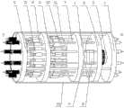
本发明的目的是通过这样的技术方案实现的,它包括有十个电流输入端R、十个电流输出端S和设置在电流输入端与电流输出端之间的电流循环智能融冰装置主体,所述电流循环智能融冰装置主体包括有汇流导电板、分流导电板、隔离板、参考电压板和安装有电流输出端的电流输出板,十个电流输入端R固定在汇流导电板上,汇流导电板与分流导电板之间由作为取电互感器的一次线圈导电棒连接,在分流导电板上设置有十根导电杆,十根导电杆穿过隔离板连接到参考电压板上,在电流输出板和隔离板之间设置有十个带旁路开关的断路器,每个断路器的灭弧室一端均与电流输出板固定并连接到一个对应的电流输出端S,断路器的灭弧室另一端穿过参考电压板,并与一个断路器的执行机构连接,在分流导电板上还设置有智能控制器和内置覆冰参数监测单元,智能控制器和内置覆冰参数监测单元位于隔离板与分流导电板之间,智能控制器分别与内置覆冰参数监测单元和执行机构电连接。The purpose of the present invention is achieved through such a technical solution, which includes ten current input terminals R, ten current output terminals S and a current circulation intelligent ice-melting device main body arranged between the current input terminals and the current output terminals, The main body of the current circulation intelligent ice-melting device includes a confluence conductive plate, a shunt conductive plate, an isolation plate, a reference voltage plate, and a current output plate equipped with current output terminals. Ten current input terminals R are fixed on the confluence conductive plate, and the confluence conduction The plate and the shunt conductive plate are connected by a primary coil conductive rod as a power-taking transformer. Ten conductive rods are arranged on the shunt conductive plate, and the ten conductive rods pass through the isolation plate and are connected to the reference voltage plate. There are ten circuit breakers with bypass switches between the board and the isolation board. One end of the arc extinguishing chamber of each circuit breaker is fixed with the current output board and connected to a corresponding current output terminal S. The arc extinguishing chamber of the circuit breaker The other end passes through the reference voltage board and is connected to an actuator of a circuit breaker. An intelligent controller and a built-in ice coating parameter monitoring unit are also arranged on the shunt conductive plate. The intelligent controller and the built-in ice coating parameter monitoring unit are located on the isolation board Between the shunt conductive plate, the intelligent controller is electrically connected with the built-in ice coating parameter monitoring unit and the actuator respectively.
进一步,所述智能控制器、执行机构和内置覆冰参数监测单元由以参考电压板为基准的取电互感器供电。Further, the intelligent controller, the actuator and the built-in icing parameter monitoring unit are powered by a power-taking transformer based on the reference voltage board.
进一步,所述断路器和旁路开关均设置独立的执行机构。Further, both the circuit breaker and the bypass switch are provided with independent actuators.
进一步,所述装置还包括有外置覆冰参数监测单元,外置覆冰参数监测单元用于监测环境参数、导线温度、导线电流和导线覆冰荷载状况,并将监测到的数据通过无线通信和有线连接两种方式发送至智能控制器。Further, the device also includes an external icing parameter monitoring unit, which is used to monitor environmental parameters, conductor temperature, conductor current and conductor icing load status, and transmit the monitored data through wireless communication Send it to the intelligent controller in two ways: wired connection and wired connection.
进一步,所述分流导电板包括有绝缘子板和导电子板,导电子板嵌于绝缘子板的中心位置,导电子板上设置有十个用于穿过导电杆的孔和一个用于安装取电互感器的孔。Further, the shunt conductive plate includes an insulator plate and a conductive sub-plate, the conductive sub-plate is embedded in the center of the insulator plate, and the conductive sub-plate is provided with ten holes for passing through the conductive rod and one for installing and taking electricity. hole for the transformer.
进一步,所述装置还包括有两根分别依次穿过汇流导电板、分流导电板、隔离板、参考电压板和电流输出板的绝缘杆。Further, the device also includes two insulating rods which respectively pass through the busbar conductive plate, the shunt conductive plate, the isolation plate, the reference voltage plate and the current output plate in sequence.
进一步,所述装置还包括有绝缘外壳,汇流导电板、分流导电板、隔离板、参考电压板和电流输出板均安装在绝缘外壳内。Further, the device also includes an insulating shell, and the converging conductive plate, the shunting conductive plate, the isolation plate, the reference voltage plate and the current output plate are all installed in the insulating shell.
由于采用了上述技术方案,本发明具有如下的优点:Owing to adopting above-mentioned technical scheme, the present invention has following advantage:
本发明可以通过内置和外置二种方式的覆冰参数监测单元检测到的外部环境条件判断是否出现覆冰现象,智能控制器控制断路器的开合,将十分裂导线输电线路传输的负荷电流转移至一部分子导线上,增大子导线电流密度达到融冰目的,智能控制器根据取电传感器测量的负荷电流和外部环境参数自动计算融冰时间,在该部分子导线完融冰后,控制断路器将电流依次转移至另一部分子导线上,直至十根子导线表面冰层全部融化脱落,然后恢复正常工作状态。本发明在工作过程中,由智能控制器整体控制,智能控制器工作的判断标准由取电互感器和内置和外置二种方式的覆冰参数监测单元提供,可以实现无人工干预的输电线路融冰工作。In the present invention, the external environmental conditions detected by the built-in and external icing parameter monitoring units can be used to judge whether icing occurs. Transfer to a part of the sub-conductor, increase the current density of the sub-conductor to achieve the purpose of ice melting, the intelligent controller automatically calculates the ice-melting time according to the load current measured by the power-taking sensor and the external environment parameters, after the part of the sub-conductor completes the ice melting, the control The circuit breaker transfers the current to another part of the sub-conductors in turn until the ice layer on the surface of the ten sub-conductors melts and falls off, and then returns to normal working condition. In the working process of the present invention, it is controlled by the intelligent controller as a whole, and the judgment standard of the intelligent controller is provided by the power transformer and the ice-covered parameter monitoring unit in two ways, the built-in and the external, which can realize the transmission line without manual intervention Melting works.
本发明的其他优点、目标和特征在某种程度上将在随后的说明书中进行阐述,并且在某种程度上,基于对下文的考察研究对本领域技术人员而言将是显而易见的,或者可以从本发明的实践中得到教导。本发明的目标和其他优点可以通过下面的说明书和权利要求书来实现和获得。Other advantages, objects and features of the present invention will be set forth in the following description to some extent, and to some extent, will be obvious to those skilled in the art based on the investigation and research below, or can be obtained from It is taught in the practice of the present invention. The objects and other advantages of the invention will be realized and attained by the following description and claims.
附图说明Description of drawings
本发明的附图说明如下。The accompanying drawings of the present invention are described as follows.
图1为本发明的结构示意图;Fig. 1 is a structural representation of the present invention;
图2为本发明的工作流程图;Fig. 2 is a work flow chart of the present invention;
图3为智能控制器的程序控制框图;Fig. 3 is the program control block diagram of intelligent controller;
图4为分流导电板结构示意图。Fig. 4 is a schematic diagram of the structure of the shunt conductive plate.
图中:1. 汇流导电板;2. 取电互感器;3. 分流导电板;4. 隔离板;5. 参考电压板;6. 绝缘输出板;7. 导电杆;8. 内置覆冰参数监测单元;9. 智能控制器;10. 断路器;11. 旁路开关;12. 执行机构;13. 导电子板;14. 绝缘子板;15. 绝缘外壳;16. 绝缘杆。In the figure: 1. Convergence conductive plate; 2. Power transformer; 3. Shunt conductive plate; 4. Isolation plate; 5. Reference voltage plate; 6. Insulation output plate; 7. Conductive rod; Monitoring unit; 9. Intelligent controller; 10. Circuit breaker; 11. Bypass switch; 12. Executing agency; 13. Conductive electronic board; 14. Insulator board;
具体实施方式Detailed ways
下面结合附图和实施例对本发明作进一步说明。The present invention will be further described below in conjunction with drawings and embodiments.
如图1所示,电流输入端R经汇流导电板1将十分裂导线各子导线的传输电流集中,利用取电互感器2测量十分裂导线输电线路传输电流总值,经分流导电板3和导电杆7传输至参考电压板5,参考电压板5连接着所有断路器10和并联旁路开关11的一端,断路器10和旁路开关11的另一端分别连接着固定于绝缘输出板6的子导线电流输出端子S,且每一根子导线对应连接着一个断路器10和一个并联旁路开关11,十个断路器10初始状态为闭合状态,十个并联旁路开关11初始状态处于开断状态。智能控制器9根据外置覆冰参数监测单元和内置覆冰参数监测单元8测量结果和内置的控制程序,发出是否启动融冰指令。隔离板4用于将执行机构12与智能控制器9、内置覆冰参数监测单元8进行隔离和保护。参考电压板5是取电互感器的电源电压参考点,取电互感器为执行机构12、内置覆冰参数监测单元8和智能控制器9提供工作电源。旁路开关11在断路器10失效时提供电流通道。绝缘杆16分别连接着汇流导电板1、分流导电板3、隔离板4、参考电压板5和绝缘输出板6,用于机械固定和安装定位。As shown in Figure 1, the current input terminal R concentrates the transmission current of each sub-conductor of the ten-split conductor through the confluence conductive plate 1, and uses the power-
如图4所示,分流导电板3包括有绝缘子板14和导电子板13,导电子板13嵌于绝缘子板3的中心位置,导电子板13上设置有十个用于穿过导电杆7的孔,并在其中心设置一个用于安装取电互感器2一次导电棒的孔。As shown in Figure 4, the shunt conductive plate 3 includes an
若智能控制器9判断不需要启动融冰,则智能控制器9发出指令至执行机构12,执行机构确定断路器10和旁路开关11保持在初始状态,使十分裂各子导线按正常传输电流状态下运行。If the intelligent controller 9 judges that it is not necessary to start melting the ice, the intelligent controller 9 sends an instruction to the
当智能控制器9判断需要启动融冰时,通过控制相应断路器的开关,可以执行以下融冰方式:When the intelligent controller 9 judges that ice melting needs to be started, by controlling the switch of the corresponding circuit breaker, the following ice melting methods can be implemented:
融冰方式一Melting method one
1) 根据装置内置和外置的环境参数、覆冰状态和取电传感器测量的负荷电流的测量结果,利用十分裂导线输电线路电流循环智能融冰装置将输电线路传输电流自动转移至其中子导线Ⅰ、子导线Ⅱ、子导线Ⅲ、子导线Ⅳ和子导线Ⅴ,使该五根子导线电流增大、发热,根据覆冰状态和取电传感器测量的负荷电流自动计算融冰时间,在自动计算的时间内融化该子导线的冰层。智能控制器9发出指令至执行机构12,然后由执行机构12确定子导线Ⅵ、子导线Ⅶ、子导线Ⅷ、子导线Ⅸ、子导线X所连接的断路器10动作“开断”使十分裂导线输电线路传输电流转移至子导线Ⅰ、子导线Ⅱ、子导线Ⅲ、子导线Ⅳ和子导线Ⅴ,使子导线Ⅰ、子导线Ⅱ、子导线Ⅲ、子导线Ⅳ和子导线Ⅴ发热、融冰,由智能控制器9确定融冰时间。1) According to the measurement results of the built-in and external environmental parameters of the device, the icing state and the load current measured by the power-taking sensor, the transmission current of the transmission line is automatically transferred to the neutral wire by using the current circulation intelligent ice-melting device of the split wire transmission line Ⅰ, sub-conductor II, sub-conductor III, sub-conductor IV and sub-conductor V, so that the current of the five sub-conductors increases and heats up, and the ice-melting time is automatically calculated according to the icing state and the load current measured by the power-taking sensor. Melt the ice layer of the sub-conductor within the time. The intelligent controller 9 sends an instruction to the
2) 子导线Ⅰ、子导线Ⅱ、子导线Ⅲ、子导线Ⅳ和子导线Ⅴ子导线冰层融化结束,十分裂导线输电线路电流循环融冰装置自动将输电线路传输电流智能转移至子导线Ⅵ、子导线Ⅶ、子导线Ⅷ、子导线Ⅸ和子导线X,使该五根子导线电流增大、发热,根据覆冰状态和取电传感器测量的负荷电流自动计算融冰时间,在自动计算的时间内融化该子导线的冰层。步骤1)中,如果子导线Ⅰ、子导线Ⅱ、子导线Ⅲ、子导线Ⅳ和子导线Ⅴ融冰结束,由智能控制器9发出指令至执行机构12,首先使子导线Ⅵ、子导线Ⅶ、子导线Ⅷ、子导线Ⅸ和子导线X所连接的断路器10动作“闭合”,然后子导线Ⅰ、子导线Ⅱ、子导线Ⅲ、子导线Ⅳ和子导线Ⅴ所连接的断路器10动作“开断”,则十分裂导线输电线路传输电流转移至子导线Ⅵ、子导线Ⅶ、子导线Ⅷ、子导线Ⅸ和子导线X,使子导线Ⅵ、子导线Ⅶ、子导线Ⅷ、子导线Ⅸ和子导线X发热、融冰,由智能控制器9确定融冰时间。2) After the sub-conductor I, sub-conductor II, sub-conductor III, sub-conductor IV and sub-conductor V have finished melting the ice layer, the current circulation ice melting device of the very cracked conductor transmission line automatically transfers the transmission current of the transmission line intelligently to the sub-conductor VI, The sub-conductor VII, sub-conductor VIII, sub-conductor IX and sub-conductor X make the current of the five sub-conductors increase and generate heat, and the ice-melting time is automatically calculated according to the icing state and the load current measured by the power-taking sensor, within the automatically calculated time Melt the ice layer of the sub-wire. In step 1), if sub-conductor I, sub-conductor II, sub-conductor III, sub-conductor IV and sub-conductor V have been thawed, the intelligent controller 9 sends an instruction to the
3) 当10根子导线的冰层全部融冰结束,智能装置恢复正常传输电流的导通状态,等待下一个覆冰过程和启动下一次融冰过程,以这种方法达到循环除冰的目的。3) When the ice layer of the 10 sub-conductors is completely melted, the smart device returns to the conduction state of the normal transmission current, waits for the next ice coating process and starts the next ice melting process, and achieves the purpose of cyclic deicing in this way.
(2) 融冰方式二(2)
1) 根据装置内置和外置的环境参数、覆冰状态和取电传感器测量的负荷电流的测量结果,利用十分裂导线输电线路电流循环智能融冰装置将输电线路传输电流自动转移至其中子导线Ⅰ、子导线Ⅱ,使该二根子导线电流增大、发热,根据覆冰状态和取电传感器测量的负荷电流自动计算融冰时间,在自动计算的时间内融化该子导线的冰层。1) According to the measurement results of the built-in and external environmental parameters of the device, the icing state and the load current measured by the power-taking sensor, the transmission current of the transmission line is automatically transferred to the neutral wire by using the current circulation intelligent ice-melting device of the split wire transmission line Ⅰ. Sub-conductor II. Make the current of the two sub-conductors increase and generate heat. The ice-melting time is automatically calculated according to the ice-covered state and the load current measured by the power-taking sensor, and the ice layer of the sub-conductor is melted within the automatically calculated time.
2) 子导线Ⅰ、子导线Ⅱ冰层融化结束,根据装置内置和外置的环境参数、覆冰状态和取电传感器测量的负荷电流的测量结果,利用十分裂导线输电线路电流循环智能融冰装置将输电线路传输电流自动转移至其中子导线Ⅲ、子导线Ⅳ,使该二根子导线电流增大、发热,根据覆冰状态和取电传感器测量的负荷电流自动计算融冰时间,在自动计算的时间内融化该子导线的冰层。2) After the melting of sub-conductor Ⅰ and sub-conductor Ⅱ is over, according to the built-in and external environmental parameters of the device, the icing state and the measurement results of the load current measured by the power-taking sensor, the current cycle of the very cracked conductor transmission line is used to intelligently melt the ice The device automatically transfers the transmission current of the transmission line to its sub-conductor III and sub-conductor IV, so that the current of the two sub-conductors increases and generates heat, and the ice-melting time is automatically calculated according to the icing state and the load current measured by the power-taking sensor. Melt the ice layer of the sub-conductor within the time.
3) 子导线Ⅲ、子导线Ⅳ冰层融化结束,根据装置内置和外置的环境参数、覆冰状态和取电传感器测量的负荷电流的测量结果,利用十分裂导线输电线路电流循环智能融冰装置将输电线路传输电流自动转移至其中子导线Ⅴ、子导线Ⅵ,使该二根子导线电流增大、发热,根据覆冰状态和取电传感器测量的负荷电流自动计算融冰时间,在自动计算的时间内融化该子导线的冰层。3) After the melting of the sub-conductor III and sub-conductor IV, according to the built-in and external environmental parameters of the device, the icing state and the measurement results of the load current measured by the power-taking sensor, the current cycle of the very cracked conductor transmission line is used to intelligently melt the ice The device automatically transfers the transmission current of the transmission line to the sub-conductor V and sub-conductor VI, so that the current of the two sub-conductors increases and heats up, and the ice-melting time is automatically calculated according to the icing state and the load current measured by the power-taking sensor. Melt the ice layer of the sub-conductor within the time.
4) 子导线Ⅴ、子导线Ⅵ冰层融化结束,根据装置内置和外置的环境参数、覆冰状态和取电传感器测量的负荷电流的测量结果,利用十分裂导线输电线路电流循环智能融冰装置将输电线路传输电流自动转移至其中子导线Ⅶ、子导线Ⅷ,使该二根子导线电流增大、发热,根据覆冰状态和取电传感器测量的负荷电流自动计算融冰时间,在自动计算的时间内融化该子导线的冰层。4) After the melting of the sub-conductor Ⅴ and sub-conductor Ⅵ ice layer is over, according to the built-in and external environmental parameters of the device, the ice-covered state and the measurement results of the load current measured by the power-taking sensor, the current circulation of the very cracked conductor transmission line is used to intelligently melt the ice The device automatically transfers the transmission current of the transmission line to the sub-conductor VII and sub-conductor VIII, so that the current of the two sub-conductors increases and heats up, and the ice-melting time is automatically calculated according to the ice-covered state and the load current measured by the power-taking sensor. Melt the ice layer of the sub-conductor within the time.
5) 子导线Ⅶ、子导线Ⅷ冰层融化结束,根据装置内置和外置的环境参数、覆冰状态和取电传感器测量的负荷电流的测量结果,利用十分裂导线输电线路电流循环智能融冰装置将输电线路传输电流自动转移至其中子导线Ⅸ、子导线X,使该二根子导线电流增大、发热,根据覆冰状态和取电传感器测量的负荷电流自动计算融冰时间,在自动计算的时间内融化该子导线的冰层。5) After the ice layer of sub-conductor VII and sub-conductor VIII has melted, according to the built-in and external environmental parameters of the device, the ice-covered state and the measurement results of the load current measured by the power-taking sensor, the current circulation of the very cracked conductor transmission line is used to intelligently melt the ice The device automatically transfers the transmission current of the transmission line to the sub-conductor IX and sub-conductor X, so that the current of the two sub-conductors increases and heats up, and the ice-melting time is automatically calculated according to the icing state and the load current measured by the power-taking sensor. Melt the ice layer of the sub-conductor within the time.
6) 当10根子导线的冰层全部融冰结束,智能装置恢复正常传输电流的导通状态,等待下一个覆冰过程和启动下一次融冰过程,以这种方法达到循环除冰的目的。6) When the ice layer of the 10 sub-conductors is completely melted, the smart device returns to the conduction state of the normal transmission current, waits for the next ice coating process and starts the next ice melting process, and achieves the purpose of cyclic deicing in this way.
(3) 融冰方式三(3) Melting method three
1) 根据装置内置和外置的环境参数、覆冰状态和取电传感器测量的负荷电流的测量结果,利用十分裂导线输电线路电流循环智能融冰装置将输电线路传输电流自动转移至其中子导线Ⅰ、子导线Ⅱ、子导线Ⅲ、子导线Ⅳ,使该四根子导线电流增大、发热,根据覆冰状态和取电传感器测量的负荷电流自动计算融冰时间,在自动计算的时间内融化该子导线的冰层。1) According to the measurement results of the built-in and external environmental parameters of the device, the icing state and the load current measured by the power-taking sensor, the transmission current of the transmission line is automatically transferred to the neutral wire by using the current circulation intelligent ice-melting device of the split wire transmission line Ⅰ, sub-conductor II, sub-conductor III, and sub-conductor IV, make the current of the four sub-conductors increase and generate heat, and automatically calculate the melting time according to the icing state and the load current measured by the power sensor, and melt within the automatically calculated time The ice layer of the sub-conductor.
2) 子导线Ⅰ、子导线Ⅱ、子导线Ⅲ、子导线Ⅳ冰层融化结束,根据装置内置和外置的环境参数、覆冰状态和取电传感器测量的负荷电流的测量结果,利用十分裂导线输电线路电流循环智能融冰装置将输电线路传输电流自动转移至其中子导线Ⅴ、子导线Ⅵ、子导线Ⅶ、子导线Ⅷ,使该五根子导线电流增大、发热,根据覆冰状态和取电传感器测量的负荷电流自动计算融冰时间,在自动计算的时间内融化该子导线的冰层。2) After the melting of the sub-conductor I, sub-conductor II, sub-conductor III, and sub-conductor IV, the ice layer is completely melted. According to the measurement results of the built-in and external environmental parameters, ice-covered state and load current measured by the power-taking sensor, use the ten-crack The current circulation intelligent ice-melting device of the wire transmission line automatically transfers the transmission current of the transmission line to its sub-conductor V, sub-conductor VI, sub-conductor VII, and sub-conductor VIII, so that the current of the five sub-conductors increases and heats up. The load current measured by the power-taking sensor automatically calculates the ice-melting time, and melts the ice layer of the sub-conductor within the automatically calculated time.
3) 子导线Ⅴ、子导线Ⅵ、子导线Ⅶ、子导线Ⅷ冰层融化结束,根据装置内置和外置的环境参数、覆冰状态和取电传感器测量的负荷电流的测量结果,利用十分裂导线输电线路电流循环智能融冰装置将输电线路传输电流自动转移至其中子导线Ⅸ、子导线X、子导线Ⅰ、子导线Ⅱ,使该四根子导线电流增大、发热,根据覆冰状态和取电传感器测量的负荷电流自动计算融冰时间,在自动计算的时间内融化该子导线的冰层。3) After the melting of sub-conductor V, sub-conductor VI, sub-conductor VII and sub-conductor VIII is completed, according to the measurement results of the built-in and external environmental parameters of the device, the ice-covered state and the load current measured by the power-taking sensor, use the ten-crack The current circulation intelligent ice-melting device of the wire transmission line automatically transfers the transmission current of the transmission line to its sub-conductor IX, sub-conductor X, sub-conductor I, and sub-conductor II, so that the current of the four sub-conductors increases and heats up. The load current measured by the power-taking sensor automatically calculates the ice-melting time, and melts the ice layer of the sub-conductor within the automatically calculated time.
3) 当10根子导线的冰层全部融冰结束,智能装置恢复正常传输电流的导通状态,等待下一个覆冰过程和启动下一次融冰过程,以这种方法达到循环除冰的目的。3) When the ice layer of the 10 sub-conductors is completely melted, the smart device returns to the conduction state of the normal transmission current, waits for the next ice coating process and starts the next ice melting process, and achieves the purpose of cyclic deicing in this way.
(4) 融冰方式四(4) Melting method four
1) 根据装置内置和外置的环境参数、覆冰状态和取电传感器测量的负荷电流的测量结果,利用十分裂导线输电线路电流循环智能融冰装置将输电线路传输电流自动转移至其中子导线Ⅰ、子导线Ⅱ、子导线Ⅲ,使该三根子导线电流增大、发热,根据覆冰状态和取电传感器测量的负荷电流自动计算融冰时间,在自动计算的时间内融化该子导线的冰层。1) According to the measurement results of the built-in and external environmental parameters of the device, the icing state and the load current measured by the power-taking sensor, the transmission current of the transmission line is automatically transferred to the neutral wire by using the current circulation intelligent ice-melting device of the split wire transmission line Ⅰ, sub-conductor II, and sub-conductor III, increase the current of the three sub-conductors and generate heat, and automatically calculate the ice-melting time according to the ice-covered state and the load current measured by the power-taking sensor, and melt the ice of the sub-conductor within the automatically calculated time layer.
2) 子导线Ⅰ、子导线Ⅱ、子导线Ⅲ冰层融化结束,根据装置内置和外置的环境参数、覆冰状态和取电传感器测量的负荷电流的测量结果,利用十分裂导线输电线路电流循环智能融冰装置将输电线路传输电流自动转移至其中子导线Ⅳ、子导线Ⅴ、子导线Ⅵ,使该三根子导线电流增大、发热,根据覆冰状态和取电传感器测量的负荷电流自动计算融冰时间,在自动计算的时间内融化该子导线的冰层。2) After the melting of sub-conductor Ⅰ, sub-conductor Ⅱ and sub-conductor Ⅲ is completed, according to the measurement results of the built-in and external environmental parameters of the device, the icing state and the load current measured by the power-taking sensor, the transmission line current of the very cracked conductor is used The circulating intelligent ice-melting device automatically transfers the transmission current of the transmission line to its sub-conductor IV, sub-conductor V, and sub-conductor VI, so that the current of the three sub-conductors increases and heats up, and is automatically calculated according to the icing state and the load current measured by the power-taking sensor Ice melting time, to melt the ice layer of the sub-conductor within the automatically calculated time.
3) 子导线Ⅳ、子导线Ⅴ、子导线Ⅵ冰层融化结束,根据装置内置和外置的环境参数、覆冰状态和取电传感器测量的负荷电流的测量结果,利用十分裂导线输电线路电流循环智能融冰装置将输电线路传输电流自动转移至其中子导线Ⅶ、子导线Ⅷ、子导线Ⅸ,使该三根子导线电流增大、发热,根据覆冰状态和取电传感器测量的负荷电流自动计算融冰时间,在自动计算的时间内融化该子导线的冰层。3) After the melting of the sub-conductor IV, sub-conductor V and sub-conductor VI, the ice layer of the sub-conductor Ⅴ, sub-conductor Ⅵ and sub-conductor Ⅵ is completed. According to the measurement results of the built-in and external environmental parameters of the device, the ice-covered state and the load current measured by the power-taking sensor, the transmission line current of the very cracked conductor is used to The circulating intelligent ice-melting device automatically transfers the transmission current of the transmission line to its sub-conductor VII, sub-conductor VIII, and sub-conductor IX, so that the current of the three sub-conductors increases and heats up, and is automatically calculated according to the icing state and the load current measured by the power-taking sensor Ice melting time, to melt the ice layer of the sub-conductor within the automatically calculated time.
4) 子导线Ⅶ、子导线Ⅷ、子导线Ⅸ冰层融化结束,根据装置内置和外置的环境参数、覆冰状态和取电传感器测量的负荷电流的测量结果,利用十分裂导线输电线路电流循环智能融冰装置将输电线路传输电流自动转移至其中子导线X、子导线Ⅰ、子导线Ⅱ,使该三根子导线电流增大、发热,根据覆冰状态和取电传感器测量的负荷电流自动计算融冰时间,在自动计算的时间内融化该子导线的冰层。4) After the melting of sub-conductor VII, sub-conductor VIII and sub-conductor IX ends, according to the measurement results of the built-in and external environmental parameters of the device, the ice-covered state and the load current measured by the power-taking sensor, the transmission line current of the ten-cracked conductor is used to The circulating intelligent ice-melting device automatically transfers the transmission current of the transmission line to its sub-conductor X, sub-conductor I, and sub-conductor II, so that the current of the three sub-conductors increases and heats up, and is automatically calculated according to the icing state and the load current measured by the power-taking sensor Ice melting time, to melt the ice layer of the sub-conductor within the automatically calculated time.
5) 当10根子导线的冰层全部融冰结束,智能装置恢复正常传输电流的导通状态,等待下一个覆冰过程和启动下一次融冰过程,以这种方法达到循环除冰的目的。5) When the ice layer of the 10 sub-conductors is completely melted, the smart device returns to the conduction state of the normal transmission current, waits for the next ice coating process and starts the next ice melting process, and achieves the purpose of cyclic deicing in this way.
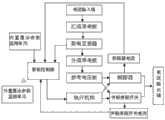
如图2所示,外置覆冰参数监测单元实时监测环境参数、导线温度、导线电流和导线覆冰荷载状况,并将上述参数通过无线方式实时传输给智能控制器9,内置覆冰参数监测单元8实时监测环境参数、导线温度、导线电流和导线覆冰荷载状况,并将上述参数通过有线方式实时传输给智能控制器9,智能控制器9根据外置覆冰参数监测单元、内置覆冰参数监测单元8和取电互感器2所提供的数据,根据内置的控制程序发出指令至执行机构12决定断路器10和并联旁路开关11的工作状态。As shown in Figure 2, the external icing parameter monitoring unit monitors the environmental parameters, wire temperature, wire current and wire icing load in real time, and transmits the above parameters to the intelligent controller 9 in real time through wireless mode. The built-in icing parameter monitoring The
最后说明的是,以上实施例仅用以说明本发明的技术方案而非限制,尽管参照较佳实施例对本发明进行了详细说明,本领域的普通技术人员应当理解,可以对本发明的技术方案进行修改或者等同替换,而不脱离本技术方案的宗旨和范围,其均应涵盖在本发明的权利要求范围当中。Finally, it is noted that the above embodiments are only used to illustrate the technical solutions of the present invention without limitation. Although the present invention has been described in detail with reference to the preferred embodiments, those of ordinary skill in the art should understand that the technical solutions of the present invention can be carried out Modifications or equivalent replacements, without departing from the spirit and scope of the technical solution, should be included in the scope of the claims of the present invention.
Claims (7)
Priority Applications (1)
| Application Number | Priority Date | Filing Date | Title |
|---|---|---|---|
| CN201310021132.8ACN103050919B (en) | 2013-02-16 | 2013-02-16 | Intelligent device for circularly melting ice on power transmission line with ten split sub-conductors by current |
Applications Claiming Priority (1)
| Application Number | Priority Date | Filing Date | Title |
|---|---|---|---|
| CN201310021132.8ACN103050919B (en) | 2013-02-16 | 2013-02-16 | Intelligent device for circularly melting ice on power transmission line with ten split sub-conductors by current |
Publications (2)
| Publication Number | Publication Date |
|---|---|
| CN103050919Atrue CN103050919A (en) | 2013-04-17 |
| CN103050919B CN103050919B (en) | 2015-04-08 |
Family
ID=48063471
Family Applications (1)
| Application Number | Title | Priority Date | Filing Date |
|---|---|---|---|
| CN201310021132.8AActiveCN103050919B (en) | 2013-02-16 | 2013-02-16 | Intelligent device for circularly melting ice on power transmission line with ten split sub-conductors by current |
Country Status (1)
| Country | Link |
|---|---|
| CN (1) | CN103050919B (en) |
Citations (4)
| Publication number | Priority date | Publication date | Assignee | Title |
|---|---|---|---|---|
| JP2007166836A (en)* | 2005-12-15 | 2007-06-28 | Tokyo Electric Power Services Co Ltd | Snow and ice falling-off prevention device |
| CN101409438A (en)* | 2008-07-25 | 2009-04-15 | 中国电力工程顾问集团西北电力设计院 | Ice-melting method suitable for transmission line with multiple fission conductor |
| CN101431224A (en)* | 2008-12-12 | 2009-05-13 | 武汉大学 | De-icing technology for overhead transmission line |
| CN101710683A (en)* | 2009-12-25 | 2010-05-19 | 重庆大学 | Intelligent circulation anti-icing method for transmitting current by split lead |
- 2013
- 2013-02-16CNCN201310021132.8Apatent/CN103050919B/enactiveActive
Patent Citations (4)
| Publication number | Priority date | Publication date | Assignee | Title |
|---|---|---|---|---|
| JP2007166836A (en)* | 2005-12-15 | 2007-06-28 | Tokyo Electric Power Services Co Ltd | Snow and ice falling-off prevention device |
| CN101409438A (en)* | 2008-07-25 | 2009-04-15 | 中国电力工程顾问集团西北电力设计院 | Ice-melting method suitable for transmission line with multiple fission conductor |
| CN101431224A (en)* | 2008-12-12 | 2009-05-13 | 武汉大学 | De-icing technology for overhead transmission line |
| CN101710683A (en)* | 2009-12-25 | 2010-05-19 | 重庆大学 | Intelligent circulation anti-icing method for transmitting current by split lead |
Non-Patent Citations (2)
| Title |
|---|
| 张志劲等: "四分裂导线运行电流分组融冰方法与现场试验", 《电网技术》* |
| 舒立春等: "智能循环电流融冰方法及临界融冰电流研究", 《电工技术学报》* |
Also Published As
| Publication number | Publication date |
|---|---|
| CN103050919B (en) | 2015-04-08 |
Similar Documents
| Publication | Publication Date | Title |
|---|---|---|
| CN101710683B (en) | Intelligent circulation anti-icing method for transmitting current by split lead | |
| CN101552444A (en) | System and method for deicing of power line cables | |
| KR20170034426A (en) | Method for transmitting electrical energy | |
| CN102227074A (en) | De-icing and anti-freezing system for transmission lines in operation | |
| CN103094869B (en) | Electric transmission line current circulation intelligent ice melting device of five divided conductors | |
| CN103050917B (en) | Intelligent device for circularly melting ice on power transmission line with twelve split sub-conductors by current | |
| CN103050918B (en) | Intelligent device for circularly melting ice on power transmission line with four split sub-conductors by current | |
| CN103050920B (en) | Binary fission wire transmission line current cycle intelligence deicing device | |
| CN107727254A (en) | A wireless real-time monitoring device for reactor operating temperature | |
| CN101295863A (en) | Ensure stable operation of the power grid without power outage Automatic heating of anti-ice and snow overhead power lines | |
| CN201178294Y (en) | Automation apparatus of composite distribution network | |
| CN103050923B (en) | Intelligent device for circularly melting ice on power transmission line with eight split sub-conductors by current | |
| CN113078603A (en) | Ice melting device for power line | |
| CN103050921B (en) | Intelligent device for circularly melting ice on power transmission line with six split sub-conductors by current | |
| CN103066543B (en) | Current circulating smart ice melting device of three-bundle-conductor electric transmission line | |
| CN103050922B (en) | Intelligent device for circularly melting ice on power transmission line with eleven split sub-conductors by current | |
| US20170149379A1 (en) | Interconnect device for use in islanding a microgrid | |
| CN103050919B (en) | Intelligent device for circularly melting ice on power transmission line with ten split sub-conductors by current | |
| CN103078286B (en) | Current-circulating intelligent ice-melting device for hepta-bundled conductor power transmission line | |
| CN103078285B (en) | Nine-bundle conductor transmission line current circulation intelligent ice-melting device | |
| CN215120054U (en) | Ice melting device for power line | |
| CN207339042U (en) | Intelligent amorphous alloy transformer platform on 10kV integration columns | |
| CN204205517U (en) | A kind of automatic defrosting snow device of transmission system | |
| CN101340070A (en) | Overhead power line capable of automatically protecting and preventing icing and automatically melting ice | |
| CN206225847U (en) | The universal attachment means of power supply vehicle of meet an emergency and low pressure aerial condutor |
Legal Events
| Date | Code | Title | Description |
|---|---|---|---|
| C06 | Publication | ||
| PB01 | Publication | ||
| C10 | Entry into substantive examination | ||
| SE01 | Entry into force of request for substantive examination | ||
| C14 | Grant of patent or utility model | ||
| GR01 | Patent grant | ||
| ASS | Succession or assignment of patent right | Owner name:STATE GRID CORPORATION OF CHINA Free format text:FORMER OWNER: HU NAN ELECTRIC POWER COMPANY RESEARCH ACADEMY Effective date:20150618 Owner name:CHONGQING UNIVERSITY DISASTER PREVENTION AND MITIG Free format text:FORMER OWNER: CHONGQING UNIVERSITY STATE GRID CORPORATION OF CHINA Effective date:20150618 | |
| C41 | Transfer of patent application or patent right or utility model | ||
| TR01 | Transfer of patent right | Effective date of registration:20150618 Address after:100031 Xicheng District West Chang'an Avenue, No. 86, Beijing Patentee after:State Grid Corporation of China Patentee after:Chongqing University Patentee after:State Grid Hunan Electric Power Company prevents and reduces natural disasters center Address before:410007 No. 79 hydroelectric power street, east pond, Hunan, Changsha Patentee before:Science Research Institute of Hunan Electric Power Co., Ltd. Patentee before:Chongqing University Patentee before:State Grid Corporation of China |