CN103049129A - Electronic device and touch sensing method - Google Patents
Electronic device and touch sensing methodDownload PDFInfo
- Publication number
- CN103049129A CN103049129ACN2012103853789ACN201210385378ACN103049129ACN 103049129 ACN103049129 ACN 103049129ACN 2012103853789 ACN2012103853789 ACN 2012103853789ACN 201210385378 ACN201210385378 ACN 201210385378ACN 103049129 ACN103049129 ACN 103049129A
- Authority
- CN
- China
- Prior art keywords
- sensing
- signal
- touch
- touch sensing
- touch sensor
- Prior art date
- Legal status (The legal status is an assumption and is not a legal conclusion. Google has not performed a legal analysis and makes no representation as to the accuracy of the status listed.)
- Pending
Links
Images


Classifications
- G—PHYSICS
- G06—COMPUTING OR CALCULATING; COUNTING
- G06F—ELECTRIC DIGITAL DATA PROCESSING
- G06F3/00—Input arrangements for transferring data to be processed into a form capable of being handled by the computer; Output arrangements for transferring data from processing unit to output unit, e.g. interface arrangements
- G06F3/01—Input arrangements or combined input and output arrangements for interaction between user and computer
- G06F3/03—Arrangements for converting the position or the displacement of a member into a coded form
- G06F3/041—Digitisers, e.g. for touch screens or touch pads, characterised by the transducing means
- G06F3/0412—Digitisers structurally integrated in a display
- G—PHYSICS
- G06—COMPUTING OR CALCULATING; COUNTING
- G06F—ELECTRIC DIGITAL DATA PROCESSING
- G06F1/00—Details not covered by groups G06F3/00 - G06F13/00 and G06F21/00
- G06F1/16—Constructional details or arrangements
- G06F1/1613—Constructional details or arrangements for portable computers
- G06F1/1626—Constructional details or arrangements for portable computers with a single-body enclosure integrating a flat display, e.g. Personal Digital Assistants [PDAs]
- G—PHYSICS
- G06—COMPUTING OR CALCULATING; COUNTING
- G06F—ELECTRIC DIGITAL DATA PROCESSING
- G06F3/00—Input arrangements for transferring data to be processed into a form capable of being handled by the computer; Output arrangements for transferring data from processing unit to output unit, e.g. interface arrangements
- G06F3/01—Input arrangements or combined input and output arrangements for interaction between user and computer
- G06F3/03—Arrangements for converting the position or the displacement of a member into a coded form
- G06F3/041—Digitisers, e.g. for touch screens or touch pads, characterised by the transducing means
- G06F3/0416—Control or interface arrangements specially adapted for digitisers
- G—PHYSICS
- G06—COMPUTING OR CALCULATING; COUNTING
- G06F—ELECTRIC DIGITAL DATA PROCESSING
- G06F3/00—Input arrangements for transferring data to be processed into a form capable of being handled by the computer; Output arrangements for transferring data from processing unit to output unit, e.g. interface arrangements
- G06F3/01—Input arrangements or combined input and output arrangements for interaction between user and computer
- G06F3/048—Interaction techniques based on graphical user interfaces [GUI]
- G06F3/0487—Interaction techniques based on graphical user interfaces [GUI] using specific features provided by the input device, e.g. functions controlled by the rotation of a mouse with dual sensing arrangements, or of the nature of the input device, e.g. tap gestures based on pressure sensed by a digitiser
- G06F3/0488—Interaction techniques based on graphical user interfaces [GUI] using specific features provided by the input device, e.g. functions controlled by the rotation of a mouse with dual sensing arrangements, or of the nature of the input device, e.g. tap gestures based on pressure sensed by a digitiser using a touch-screen or digitiser, e.g. input of commands through traced gestures
- G06F3/04886—Interaction techniques based on graphical user interfaces [GUI] using specific features provided by the input device, e.g. functions controlled by the rotation of a mouse with dual sensing arrangements, or of the nature of the input device, e.g. tap gestures based on pressure sensed by a digitiser using a touch-screen or digitiser, e.g. input of commands through traced gestures by partitioning the display area of the touch-screen or the surface of the digitising tablet into independently controllable areas, e.g. virtual keyboards or menus
- G—PHYSICS
- G09—EDUCATION; CRYPTOGRAPHY; DISPLAY; ADVERTISING; SEALS
- G09G—ARRANGEMENTS OR CIRCUITS FOR CONTROL OF INDICATING DEVICES USING STATIC MEANS TO PRESENT VARIABLE INFORMATION
- G09G3/00—Control arrangements or circuits, of interest only in connection with visual indicators other than cathode-ray tubes
- G09G3/20—Control arrangements or circuits, of interest only in connection with visual indicators other than cathode-ray tubes for presentation of an assembly of a number of characters, e.g. a page, by composing the assembly by combination of individual elements arranged in a matrix no fixed position being assigned to or needed to be assigned to the individual characters or partial characters
- G09G3/2003—Display of colours
- H—ELECTRICITY
- H04—ELECTRIC COMMUNICATION TECHNIQUE
- H04B—TRANSMISSION
- H04B1/00—Details of transmission systems, not covered by a single one of groups H04B3/00 - H04B13/00; Details of transmission systems not characterised by the medium used for transmission
- H04B1/38—Transceivers, i.e. devices in which transmitter and receiver form a structural unit and in which at least one part is used for functions of transmitting and receiving
- G—PHYSICS
- G06—COMPUTING OR CALCULATING; COUNTING
- G06F—ELECTRIC DIGITAL DATA PROCESSING
- G06F2203/00—Indexing scheme relating to G06F3/00 - G06F3/048
- G06F2203/048—Indexing scheme relating to G06F3/048
- G06F2203/04803—Split screen, i.e. subdividing the display area or the window area into separate subareas
Landscapes
- Engineering & Computer Science (AREA)
- Theoretical Computer Science (AREA)
- General Engineering & Computer Science (AREA)
- Physics & Mathematics (AREA)
- General Physics & Mathematics (AREA)
- Human Computer Interaction (AREA)
- Computer Hardware Design (AREA)
- Computer Networks & Wireless Communication (AREA)
- Signal Processing (AREA)
- Position Input By Displaying (AREA)
- User Interface Of Digital Computer (AREA)
- Electronic Switches (AREA)
Abstract
Description
Translated fromChinese技术领域technical field
本发明涉及一种电子装置及触控感测方法,且特别涉及一种电子装置以及对于两个触控传感器(touch sensor)的触控感测的方法。The present invention relates to an electronic device and a touch sensing method, and in particular to an electronic device and a touch sensing method for two touch sensors.
背景技术Background technique
图1为一种传统电子装置100的示意图。电子装置100为触控装置,如智能手机(smart phone)、个人数字助理(PDA:personal digital assistant)、平板计算机(tablet PC)、笔记型计算机(notebook PC)或桌上型计算机(desktopPC)。电子装置100包括触控显示器110及多个虚拟键(virtual key)120。各虚拟键120可检测使用者的触控操作,如同触控显示器110的运作方式。FIG. 1 is a schematic diagram of a conventional
图2为电子装置100的截面图。触控显示器110包括覆盖玻璃140、触控传感器150及液晶模块(LCM:liquid crystal module)160。显示区域132的大小尺寸与覆盖玻璃140的大小尺寸相同,且覆盖玻璃140可显露出液晶模块160所显示的图像。触控有效区域(touch active area)131为电子装置100的触控表面。触控有效区域131的尺寸大小相同于触控传感器150的尺寸大小。触控传感器150延伸超出覆盖玻璃140及液晶模块160,延伸至虚拟键120的下方。因此,触控有效区域131覆盖显示区域132及虚拟键区域133。使用者可通过手指或触控笔(stylus)触摸显示区域132或虚拟键区域133以做选择。一般而言,电子装置100可通过扫描触控传感器150来识别出使用者在触控有效区域131上所引起的触控事件的位置,而接着基于触控事件来执行动作。FIG. 2 is a cross-sectional view of the
在图2中,触控传感器150及液晶模块160为个别的元件。然而,由于工艺科技的进步,将相关元件整合为一体以降低整体系统的成本与复杂度已成为趋势。近年来,已能够通过内嵌式(in-cell)科技或外挂式(on-cell)科技来将触控传感器及液晶模块整合在一起。In FIG. 2 , the
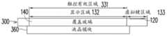
举例来说,图3为另一传统触控电子装置300的截面图。整合于电子装置300中的液晶模块360取代了在电子装置100中的触控传感器150及液晶模块160。液晶模块360与触控传感器(未于图中绘示)整合为一。然而,由于与液晶模块360相整合的触控传感器具有与液晶模块360相同的尺寸大小,所以电子装置300的触控有效区域331覆盖住显示区域132。在电子装置300中,由于虚拟键120之下并无触控传感器,因此虚拟键120无法运作。For example, FIG. 3 is a cross-sectional view of another conventional touch
发明内容Contents of the invention
本发明提出一种电子装置,此电子装置包括一个整合显示模块和一个独立触控传感器。整合显示模块可用于检测触控显示器上的触控操作,独立触控传感器可用于检测虚拟键上的触控操作。这样的触控电子装置可提供低成本的解决方案,以提升触控电子装置的效用、效率和使用者的满意度。The invention provides an electronic device, which includes an integrated display module and an independent touch sensor. The integrated display module can be used to detect the touch operation on the touch display, and the independent touch sensor can be used to detect the touch operation on the virtual key. Such a touch electronic device can provide a low-cost solution to improve the utility, efficiency and user satisfaction of the touch electronic device.
本发明另提出一种触控感测方法,此方法使用和上述电子装置相同的机制,以提升触控电子装置的效用、效率和使用者的满意度。The present invention further proposes a touch sensing method, which uses the same mechanism as the above-mentioned electronic device, so as to improve the utility, efficiency and user satisfaction of the touch electronic device.
本发明提供一种电子装置,包括与第一触控传感器相整合的显示模块、第二触控传感器及感测电路。其中,第一触控传感器响应于第一驱动信号而产生第一感测信号;第二触控传感器响应于第二驱动信号而产生第二感测信号;感测电路耦接至第一触控传感器及第二触控传感器,用以接收及分析第一感测信号及第二感测信号。The invention provides an electronic device, including a display module integrated with a first touch sensor, a second touch sensor and a sensing circuit. Wherein, the first touch sensor generates a first sensing signal in response to the first driving signal; the second touch sensor generates a second sensing signal in response to the second driving signal; the sensing circuit is coupled to the first touch sensor The sensor and the second touch sensor are used for receiving and analyzing the first sensing signal and the second sensing signal.
本发明还提供一种触控感测方法,包括下列步骤:提供第一驱动信号至与显示模块相整合的第一触控传感器,或是指示提供第一驱动信号至第一触控传感器;提供第二驱动信号至第二触控传感器;接收及分析第一感测信号,其中第一感测信号是第一触控传感器响应于第一驱动信号所产生;以及接收及分析第二感测信号,其中第二感测信号是第二触控传感器响应于第二驱动信号所产生。The present invention also provides a touch sensing method, including the following steps: providing a first driving signal to the first touch sensor integrated with the display module, or instructing to provide the first driving signal to the first touch sensor; providing The second driving signal is sent to the second touch sensor; receiving and analyzing the first sensing signal, wherein the first sensing signal is generated by the first touch sensor in response to the first driving signal; and receiving and analyzing the second sensing signal , wherein the second sensing signal is generated by the second touch sensor in response to the second driving signal.
附图说明Description of drawings
图1为一种传统触控电子装置的示意图。FIG. 1 is a schematic diagram of a traditional touch electronic device.
图2及图3为传统触控电子装置的截面图。2 and 3 are cross-sectional views of conventional touch electronic devices.
图4为根据本发明的一实施例的一种触控电子装置的部分截面图。FIG. 4 is a partial cross-sectional view of a touch electronic device according to an embodiment of the present invention.
图5为根据本发明的一实施例的一种触控电子装置的部分示意图。FIG. 5 is a partial schematic diagram of a touch electronic device according to an embodiment of the present invention.
图6为根据本发明的一实施例的一种触控电子装置的部分示意图。FIG. 6 is a partial schematic diagram of a touch electronic device according to an embodiment of the present invention.
图7为根据本发明的另一实施例的一种触控电子装置的部分示意图。FIG. 7 is a partial schematic diagram of a touch electronic device according to another embodiment of the present invention.
图8为根据本发明的一实施例的一种触控感测方法的流程图。FIG. 8 is a flowchart of a touch sensing method according to an embodiment of the present invention.
【主要元件符号说明】[Description of main component symbols]
100:电子装置100: Electronics
110:触控显示器110: Touch Monitor
120:虚拟键120: virtual key
131:触控有效区域131: Touch effective area
132:显示区域132: display area
133:虚拟键区域133: virtual key area
140:覆盖玻璃140: cover glass
150:触控传感器150: Touch sensor
160:液晶模块160: LCD module
300:电子装置300: Electronics
331:触控有效区域331: Touch effective area
360:液晶模块360: LCD module
400:电子装置400: Electronics
410:显示模块410: display module
415:触控传感器415: Touch sensor
420:虚拟键触控传感器420: virtual key touch sensor
430:导光体430: light guide
440:感测电路440: Sensing circuit
511:显示模块驱动信号511: display module driving signal
515:感测信号515: Sensing signal
521:虚拟键驱动信号521: virtual key driving signal
525:虚拟键感测信号525: Virtual key sensing signal
550:驱动电路550: drive circuit
442:发射器442: Launcher
444:接收器444: Receiver
446:接收器446: Receiver
750:驱动电路750: drive circuit
760:感测电路760: Sensing circuit
810~840:根据本发明的一实施例的触控感测方法的步骤810~840: steps of the touch sensing method according to an embodiment of the present invention
具体实施方式Detailed ways
图4为根据本发明一实施例的一种触控感测电子装置400的部分截面图。电子装置400可为智能手机(smart phone)、个人数字助理(PDA)、平板计算机(tablet PC)、笔记型计算机或桌上型计算机。电子装置400包括覆盖玻璃140、整合显示模块410、与显示模块410相整合的触控传感器415、虚拟键触控传感器420、置于虚拟键触控传感器420之下的导光体(light guide)430,以及多个虚拟键120。触控传感器415可以是内嵌式(in-cell)触控传感器或外挂式(on-cell)触控传感器。FIG. 4 is a partial cross-sectional view of a touch sensing
图5为根据本发明一实施例的触控感测电子装置400的部分示意图。电子装置400包括与触控传感器415相整合的显示模块410、虚拟键触控传感器420、感测电路440以及驱动电路550。感测电路440可以是触控控制器(touch controller),而驱动电路550可以是液晶模块驱动器(LCM driver)。感测电路440耦接至触控传感器415及触控传感器420。驱动电路550耦接至显示模块410。显示模块410可以是液晶模块(LCM)、发光二极管(LED:light-emitting diode)模块或有机发光二极管(OLED:organic light-emittingdiode)模块。FIG. 5 is a partial schematic diagram of a touch sensing
感测电路440通过扫描触控传感器415来检测显示区域132内的触控事件(touch event)。为了扫描触控传感器415,感测电路440提供驱动信号511至触控传感器415。触控传感器415响应于驱动信号511而产生感测信号515。感测电路440为了识别在显示区域132中的触控事件所发生的位置而接收及分析感测信号515。同样地,感测电路440通过扫描虚拟键触控传感器420来检测在虚拟键区域133中的触控事件。为了扫描虚拟键触控传感器420,感测电路440提供虚拟键驱动信号521至虚拟键触控传感器420。虚拟键触控传感器420响应于虚拟键驱动信号521而产生虚拟键感测信号525。感测电路440接收及分析虚拟键感测信号525,以识别在虚拟键区域133中的触控事件的位置。电子装置400可基于感测电路440所检测出的触控事件的位置来执行功能。驱动电路550驱动显示模块410来显示图像,例如电子装置400的图形使用者接口(GUI:graphical user interface)。触控传感器415、触控传感器420、感测电路440及驱动电路550皆为实体电路。The
在本发明的一实施例中,感测电路440可根据第一时序而提供显示模块驱动信号511至触控传感器415。感测电路440可根据第二时序而提供虚拟键驱动信号521至虚拟键触控传感器420。第一时序与第二时序相异。换句话说,感测电路440在不同的时间点输出驱动信号511及虚拟键驱动信号521。因此,触控传感器415的扫描不会与虚拟键触控传感器420的扫描相冲突。In an embodiment of the present invention, the
在本发明的另一实施例中,感测电路440可以第一频率来提供驱动信号511至触控传感器415。感测电路440可以第二频率来提供虚拟键驱动信号521至虚拟键触控传感器420。第一频率与第二频率相异。由于感测电路440以相异的频率来输出驱动信号511及虚拟键驱动信号521,因此,触控传感器415的扫描不会与虚拟键触控传感器420的扫描相冲突。In another embodiment of the present invention, the
在本发明的又另一实施例中,感测电路440可同时通过相同的输出端,来分别发送驱动信号511及虚拟键驱动信号521至触控传感器415及虚拟键触控传感器420。感测电路440可以相异的频率来发出驱动信号511及虚拟键驱动信号521以避免彼此的干扰。In yet another embodiment of the present invention, the
图6为电子装置400中的显示模块410、触控传感器415、虚拟键触控传感器420及感测电路440的示意图。感测电路440包括发射器442、接收器444及接收器446。接收器444耦接至触控传感器415以接收感测信号515,而接收器446耦接至虚拟键触控传感器420以接收虚拟键感测信号525。发射器442耦接至触控传感器415、虚拟键触控传感器420、接收器444及接收器446。发射器442发送驱动信号511至触控传感器415,并发送控制信号450以触发接收器444来接收感测信号515。另外,发射器442发送虚拟键驱动信号521至虚拟键触控传感器420,并发送控制信号450以触发接收器446来接收虚拟键感测信号525。FIG. 6 is a schematic diagram of the
图7为根据本发明另一实施例的触控感测电子装置400的部分示意图。在此实施例中,触控感测电子装置400包括显示模块410、与显示模块410相整合的触控传感器415、虚拟键触控传感器420、耦接至传感器415及虚拟键触控传感器420的感测电路760,以及耦接至显示模块410、触控传感器415及感测电路760的驱动电路750。驱动电路750驱动显示模块410来显示图像,如电子装置400的图形使用者接口(GUI)。感测电路760及驱动电路750皆为实体电路。FIG. 7 is a partial schematic diagram of a touch sensing
为了扫描触控传感器415及虚拟键触控传感器420以检测触控事件,感测电路760指示驱动电路750提供驱动信号511至触控传感器415,而且感测电路760自身提供虚拟键驱动信号521至虚拟键触控传感器420。触控传感器415响应于驱动信号511而产生感测信号515。感测电路760接收感测信号515,并且基于感测信号515的分析来测定在显示区域132中的触控事件的位置。在另一方面,虚拟键触控传感器420响应于虚拟键驱动信号521而产生虚拟键感测信号525。感测电路760接收虚拟键感测信号525,并且基于虚拟键感测信号525的分析来测定在虚拟键区域133中的触控事件的位置。电子装置400可基于感测电路760所检测的触控事件的位置来执行功能。In order to scan the
在本发明的一实施例中,感测电路760可根据第一时序来指示驱动电路750提供驱动信号511至触控传感器415。感测电路可根据第二时序来提供虚拟键驱动信号521至虚拟键触控传感器420。第一时序与第二时序相异,如此,触控传感器415的扫描与虚拟键触控传感器420的扫描才不会相冲突。In an embodiment of the present invention, the sensing circuit 760 can instruct the driving circuit 750 to provide the
在本发明的另一实施例中,感测电路760可以第一频率来指示驱动电路750提供驱动信号511至触控传感器415。感测电路可以第二频率来提供虚拟键驱动信号521至虚拟键触控传感器420。第一频率与第二频率相异,如此,触控传感器415的扫描与虚拟键触控传感器420的扫描才不会相冲突。In another embodiment of the present invention, the sensing circuit 760 can instruct the driving circuit 750 to provide the
图8为根据本发明一实施例的一种触控感测方法的流程图。此触控感测方法可由图5、图6或图7中的触控感测电子装置400来执行,而此触控感测方法包括下列步骤。在步骤810中,提供驱动信号511至与显示模块410相整合的触控传感器415,或是指示提供驱动信号511至触控传感器415。在步骤820中,提供虚拟键驱动信号521至虚拟键触控传感器420。在步骤830中,接收及分析感测信号515,且感测信号515是触控传感器415响应于驱动信号511所产生。在步骤840中,接收及分析虚拟键感测信号525,且虚拟键感测信号525是虚拟键触控传感器420响应于虚拟键驱动信号521所产生。FIG. 8 is a flowchart of a touch sensing method according to an embodiment of the invention. The touch sensing method can be performed by the touch sensing
上述触控感测方法的其余细节已详述于前述的本发明的实施例,因而不在此赘述。The rest of the details of the above touch sensing method have been described in the aforementioned embodiments of the present invention in detail, and thus will not be repeated here.
在前述的本发明的实施例中,分别是通过接收及分析感测信号及虚拟键感测信号来扫描触控传感器及虚拟键触控传感器。然而本发明并不限于上述的触控传感器及虚拟键触控传感器。在本发明的其他实施例中,可分别通过接收及分析相对应的感测信号,来扫描多个任意的触控传感器。In the aforementioned embodiments of the present invention, the touch sensor and the virtual key touch sensor are scanned by receiving and analyzing the sensing signal and the virtual key sensing signal respectively. However, the present invention is not limited to the aforementioned touch sensors and virtual key touch sensors. In other embodiments of the present invention, a plurality of arbitrary touch sensors can be scanned by receiving and analyzing corresponding sensing signals respectively.
综上所述,本发明使用单一感测电路来扫描至少两个触控传感器。可使用上述触控传感器的其中之一来检测在电子装置的显示区域中的触控事件。可使用上述触控传感器中的另一来检测在电子装置的虚拟键区域中的触控事件。本发明通过使用单一感测电路而非两个感测电路,以减少电子装置的成本与复杂度。此外,本发明通过使用独立的触控传感器来检测在虚拟键上的触控事件,可增加触控电子装置的有效性、效能和用户满意度。In summary, the present invention uses a single sensing circuit to scan at least two touch sensors. One of the above-mentioned touch sensors can be used to detect touch events in the display area of the electronic device. Another one of the above-mentioned touch sensors may be used to detect a touch event in the virtual key area of the electronic device. The present invention reduces the cost and complexity of the electronic device by using a single sensing circuit instead of two sensing circuits. In addition, the present invention can increase the effectiveness, performance and user satisfaction of touch electronic devices by using independent touch sensors to detect touch events on virtual keys.
虽然本发明已以实施例公开如上,然其并非用以限定本发明,本领域技术人员在不脱离本发明的精神和范围内,当可作些许的更动与润饰,故本发明的保护范围当视所附权利要求书所界定范围为准。Although the present invention has been disclosed as above with the embodiments, it is not intended to limit the present invention. Those skilled in the art can make some changes and modifications without departing from the spirit and scope of the present invention, so the protection scope of the present invention When depending on the scope defined by the appended claims shall prevail.
Claims (16)
Applications Claiming Priority (4)
| Application Number | Priority Date | Filing Date | Title |
|---|---|---|---|
| US201161546069P | 2011-10-12 | 2011-10-12 | |
| US61/546,069 | 2011-10-12 | ||
| US13/606,026 | 2012-09-07 | ||
| US13/606,026US9298304B2 (en) | 2011-10-12 | 2012-09-07 | Electronic device and touch-sensing method |
Publications (1)
| Publication Number | Publication Date |
|---|---|
| CN103049129Atrue CN103049129A (en) | 2013-04-17 |
Family
ID=47257331
Family Applications (1)
| Application Number | Title | Priority Date | Filing Date |
|---|---|---|---|
| CN2012103853789APendingCN103049129A (en) | 2011-10-12 | 2012-10-12 | Electronic device and touch sensing method |
Country Status (6)
| Country | Link |
|---|---|
| US (1) | US9298304B2 (en) |
| EP (1) | EP2581813B1 (en) |
| JP (1) | JP5727981B2 (en) |
| KR (1) | KR101427858B1 (en) |
| CN (1) | CN103049129A (en) |
| TW (1) | TWI494800B (en) |
Cited By (5)
| Publication number | Priority date | Publication date | Assignee | Title |
|---|---|---|---|---|
| CN103345316A (en)* | 2013-06-14 | 2013-10-09 | 业成光电(深圳)有限公司 | Electronic device with touch control function |
| CN103941914A (en)* | 2014-02-19 | 2014-07-23 | 友达光电股份有限公司 | Touch panel, touch display panel and sensing method of touch signal |
| CN103941905B (en)* | 2013-06-28 | 2017-03-29 | 上海天马微电子有限公司 | Embedded touch panel |
| WO2017177386A1 (en)* | 2016-04-12 | 2017-10-19 | 深圳信炜科技有限公司 | Electronic device |
| CN108108055A (en)* | 2018-01-02 | 2018-06-01 | 联想(北京)有限公司 | Touch device, touch control method and electronic equipment |
Families Citing this family (3)
| Publication number | Priority date | Publication date | Assignee | Title |
|---|---|---|---|---|
| FR3009099B1 (en)* | 2013-07-26 | 2015-08-07 | Thales Sa | TOUCH-CAPACITIVE MULTI-TOUCH SURFACE DEVICE |
| TWI622837B (en)* | 2013-10-24 | 2018-05-01 | 元太科技工業股份有限公司 | Display apparatus |
| CN106062618B (en)* | 2014-02-28 | 2019-04-16 | 凸版印刷株式会社 | Liquid crystal display device |
Citations (5)
| Publication number | Priority date | Publication date | Assignee | Title |
|---|---|---|---|---|
| CN1529869A (en)* | 2001-07-09 | 2004-09-15 | 3M | Touch screen with selective touch source |
| CN101017419A (en)* | 2005-06-30 | 2007-08-15 | 深圳市联思精密机器有限公司 | Touch control panel display |
| WO2010126072A1 (en)* | 2009-04-28 | 2010-11-04 | 日本電気株式会社 | Touch panel, touch panel manufactruing method, and electronic apparatus |
| US20110210939A1 (en)* | 2010-02-26 | 2011-09-01 | Joseph Kurth Reynolds | Varying demodulation to avoid interference |
| US20110227847A1 (en)* | 2010-03-19 | 2011-09-22 | Sony Corporation | Electrooptic device having input function |
Family Cites Families (17)
| Publication number | Priority date | Publication date | Assignee | Title |
|---|---|---|---|---|
| JPH06160118A (en) | 1992-11-26 | 1994-06-07 | Rika Kogyo Kk | Liquid crystal display device with touch switch |
| JP3368627B2 (en) | 1993-08-31 | 2003-01-20 | 双葉電子工業株式会社 | Display integrated tablet |
| TWM246655U (en) | 2003-08-20 | 2004-10-11 | Compal Electronics Inc | Mobile electronic device |
| TWI369534B (en) | 2008-02-26 | 2012-08-01 | Wintek Corp | Touch display, liquid crystal display with a built-in touch panel and fabricating method thereof |
| JP4816668B2 (en) | 2008-03-28 | 2011-11-16 | ソニー株式会社 | Display device with touch sensor |
| US8368657B2 (en) | 2008-12-01 | 2013-02-05 | Freescale Semiconductor, Inc. | Touch sensor panel using regional and local electrodes to increase number of sense locations |
| JP2011002926A (en) | 2009-06-17 | 2011-01-06 | Hitachi Ltd | Display device with tactile exhibition function |
| TWI448930B (en) | 2009-08-12 | 2014-08-11 | Innolux Corp | Touch display |
| KR101309862B1 (en) | 2009-12-10 | 2013-09-16 | 엘지디스플레이 주식회사 | Liquid Crystal Display Device Including Touch Panel |
| KR20110081040A (en) | 2010-01-06 | 2011-07-13 | 삼성전자주식회사 | Method and device for operating contents in portable terminal with transparent display |
| JP5382658B2 (en) | 2010-02-26 | 2014-01-08 | 株式会社ジャパンディスプレイ | Display device with touch sensor, touch panel, touch panel driving method, and electronic device |
| TWI435140B (en) | 2010-04-09 | 2014-04-21 | Wintek Corp | Display with touch panel |
| TW201142777A (en)* | 2010-05-28 | 2011-12-01 | Au Optronics Corp | Sensing display panel |
| US8451250B2 (en) | 2010-07-22 | 2013-05-28 | Au Optronics Corporation | Capacitive touch device and method of driving same |
| JP5539106B2 (en)* | 2010-08-23 | 2014-07-02 | 株式会社ジャパンディスプレイ | Display device with touch detection function, drive circuit, driving method of display device with touch detection function, and electronic device |
| KR101394937B1 (en)* | 2010-09-07 | 2014-05-15 | 엘지디스플레이 주식회사 | Display device having touch sensor and method for driving the same |
| US20130069894A1 (en)* | 2011-09-16 | 2013-03-21 | Htc Corporation | Electronic device and method for driving a touch sensor thereof |
- 2012
- 2012-09-07USUS13/606,026patent/US9298304B2/enactiveActive
- 2012-09-18KRKR1020120103123Apatent/KR101427858B1/enactiveActive
- 2012-10-02JPJP2012220579Apatent/JP5727981B2/enactiveActive
- 2012-10-05TWTW101136944Apatent/TWI494800B/enactive
- 2012-10-11EPEP12007053.7Apatent/EP2581813B1/enactiveActive
- 2012-10-12CNCN2012103853789Apatent/CN103049129A/enactivePending
Patent Citations (5)
| Publication number | Priority date | Publication date | Assignee | Title |
|---|---|---|---|---|
| CN1529869A (en)* | 2001-07-09 | 2004-09-15 | 3M | Touch screen with selective touch source |
| CN101017419A (en)* | 2005-06-30 | 2007-08-15 | 深圳市联思精密机器有限公司 | Touch control panel display |
| WO2010126072A1 (en)* | 2009-04-28 | 2010-11-04 | 日本電気株式会社 | Touch panel, touch panel manufactruing method, and electronic apparatus |
| US20110210939A1 (en)* | 2010-02-26 | 2011-09-01 | Joseph Kurth Reynolds | Varying demodulation to avoid interference |
| US20110227847A1 (en)* | 2010-03-19 | 2011-09-22 | Sony Corporation | Electrooptic device having input function |
Cited By (7)
| Publication number | Priority date | Publication date | Assignee | Title |
|---|---|---|---|---|
| CN103345316A (en)* | 2013-06-14 | 2013-10-09 | 业成光电(深圳)有限公司 | Electronic device with touch control function |
| CN103941905B (en)* | 2013-06-28 | 2017-03-29 | 上海天马微电子有限公司 | Embedded touch panel |
| CN103941914A (en)* | 2014-02-19 | 2014-07-23 | 友达光电股份有限公司 | Touch panel, touch display panel and sensing method of touch signal |
| CN103941914B (en)* | 2014-02-19 | 2017-04-12 | 友达光电股份有限公司 | Touch panel, touch display panel and sensing method of touch signal |
| WO2017177386A1 (en)* | 2016-04-12 | 2017-10-19 | 深圳信炜科技有限公司 | Electronic device |
| CN108108055A (en)* | 2018-01-02 | 2018-06-01 | 联想(北京)有限公司 | Touch device, touch control method and electronic equipment |
| CN108108055B (en)* | 2018-01-02 | 2021-11-16 | 联想(北京)有限公司 | Touch device, touch method and electronic equipment |
Also Published As
| Publication number | Publication date |
|---|---|
| US9298304B2 (en) | 2016-03-29 |
| EP2581813B1 (en) | 2016-04-13 |
| TW201316221A (en) | 2013-04-16 |
| KR101427858B1 (en) | 2014-08-08 |
| EP2581813A3 (en) | 2014-10-15 |
| TWI494800B (en) | 2015-08-01 |
| US20130093701A1 (en) | 2013-04-18 |
| JP2013084268A (en) | 2013-05-09 |
| EP2581813A2 (en) | 2013-04-17 |
| JP5727981B2 (en) | 2015-06-03 |
Similar Documents
| Publication | Publication Date | Title |
|---|---|---|
| CN103049129A (en) | Electronic device and touch sensing method | |
| US8537123B2 (en) | Touch sensing apparatus and sensing signal processing method thereof | |
| US11347355B2 (en) | System and method for acoustic touch and force sensing | |
| US9035914B2 (en) | Touch system including optical touch panel and touch pen, and method of controlling interference optical signal in touch system | |
| CN105393261A (en) | Display with peripherally configured ultrasonic biometric sensor | |
| US10606418B2 (en) | Ultrasonic touch detection on stylus | |
| JP2011090677A (en) | Touch panel and touch display device using the same | |
| WO2019047744A1 (en) | Liquid crystal screen module and display terminal | |
| TWI767180B (en) | Method of performing touch sensing and fingerprint sensing simultaneously and electronic device and system using the same | |
| KR20100070092A (en) | Mobile telecommunication device embodying method using the navigation apparatus | |
| US20220165079A1 (en) | Electronic apparatus having fingerprint sensing function | |
| CN102012763A (en) | Anti-interference coordinate input device and method | |
| JP2014199495A (en) | Electronic device, application operation device, and method for controlling electronic device | |
| CN1744019A (en) | Cursor Control Method | |
| US20140372915A1 (en) | Method and system for operating display device | |
| CN102609122B (en) | There is two contactor control device and the method for piezoelectricity touch-control and electromagnetic touch | |
| CN110928443B (en) | A touch position detection method and electronic device | |
| CN105204699A (en) | Capacitive touch panel with increased scan frequency | |
| WO2018166057A1 (en) | Method and electronic device for outputting touch control signals | |
| JP5866311B2 (en) | Electronic device, electronic device control method | |
| US20150169103A1 (en) | Touch display apparatus | |
| US20110199328A1 (en) | Touch screen system with acoustic and capacitive sensing | |
| CN103019452B (en) | A kind of touch-screen based on surge detection and its implementation | |
| CN203117933U (en) | Touch screen based on fluctuation detection | |
| KR102575988B1 (en) | A touch sereen implementing low power consumption using interrupt method and sensing method using the same |
Legal Events
| Date | Code | Title | Description |
|---|---|---|---|
| C06 | Publication | ||
| PB01 | Publication | ||
| C10 | Entry into substantive examination | ||
| SE01 | Entry into force of request for substantive examination | ||
| RJ01 | Rejection of invention patent application after publication | ||
| RJ01 | Rejection of invention patent application after publication | Application publication date:20130417 |