CN103037982A - Syringe with integrated needle - Google Patents
Syringe with integrated needleDownload PDFInfo
- Publication number
- CN103037982A CN103037982ACN2011800321454ACN201180032145ACN103037982ACN 103037982 ACN103037982 ACN 103037982ACN 2011800321454 ACN2011800321454 ACN 2011800321454ACN 201180032145 ACN201180032145 ACN 201180032145ACN 103037982 ACN103037982 ACN 103037982A
- Authority
- CN
- China
- Prior art keywords
- syringe
- needle
- cylindrical shell
- barrel
- cap
- Prior art date
- Legal status (The legal status is an assumption and is not a legal conclusion. Google has not performed a legal analysis and makes no representation as to the accuracy of the status listed.)
- Pending
Links
Images


Classifications
- A—HUMAN NECESSITIES
- A61—MEDICAL OR VETERINARY SCIENCE; HYGIENE
- A61M—DEVICES FOR INTRODUCING MEDIA INTO, OR ONTO, THE BODY; DEVICES FOR TRANSDUCING BODY MEDIA OR FOR TAKING MEDIA FROM THE BODY; DEVICES FOR PRODUCING OR ENDING SLEEP OR STUPOR
- A61M5/00—Devices for bringing media into the body in a subcutaneous, intra-vascular or intramuscular way; Accessories therefor, e.g. filling or cleaning devices, arm-rests
- A61M5/178—Syringes
- A61M5/31—Details
- A61M5/3129—Syringe barrels
- A61M5/3134—Syringe barrels characterised by constructional features of the distal end, i.e. end closest to the tip of the needle cannula
- A—HUMAN NECESSITIES
- A61—MEDICAL OR VETERINARY SCIENCE; HYGIENE
- A61M—DEVICES FOR INTRODUCING MEDIA INTO, OR ONTO, THE BODY; DEVICES FOR TRANSDUCING BODY MEDIA OR FOR TAKING MEDIA FROM THE BODY; DEVICES FOR PRODUCING OR ENDING SLEEP OR STUPOR
- A61M5/00—Devices for bringing media into the body in a subcutaneous, intra-vascular or intramuscular way; Accessories therefor, e.g. filling or cleaning devices, arm-rests
- A61M5/178—Syringes
- A61M5/31—Details
- A61M5/3145—Filters incorporated in syringes
- A—HUMAN NECESSITIES
- A61—MEDICAL OR VETERINARY SCIENCE; HYGIENE
- A61M—DEVICES FOR INTRODUCING MEDIA INTO, OR ONTO, THE BODY; DEVICES FOR TRANSDUCING BODY MEDIA OR FOR TAKING MEDIA FROM THE BODY; DEVICES FOR PRODUCING OR ENDING SLEEP OR STUPOR
- A61M5/00—Devices for bringing media into the body in a subcutaneous, intra-vascular or intramuscular way; Accessories therefor, e.g. filling or cleaning devices, arm-rests
- A61M5/178—Syringes
- A61M5/31—Details
- A61M5/32—Needles; Details of needles pertaining to their connection with syringe or hub; Accessories for bringing the needle into, or holding the needle on, the body; Devices for protection of needles
- A61M5/3202—Devices for protection of the needle before use, e.g. caps
- A—HUMAN NECESSITIES
- A61—MEDICAL OR VETERINARY SCIENCE; HYGIENE
- A61M—DEVICES FOR INTRODUCING MEDIA INTO, OR ONTO, THE BODY; DEVICES FOR TRANSDUCING BODY MEDIA OR FOR TAKING MEDIA FROM THE BODY; DEVICES FOR PRODUCING OR ENDING SLEEP OR STUPOR
- A61M5/00—Devices for bringing media into the body in a subcutaneous, intra-vascular or intramuscular way; Accessories therefor, e.g. filling or cleaning devices, arm-rests
- A61M5/178—Syringes
- A61M5/31—Details
- A61M5/32—Needles; Details of needles pertaining to their connection with syringe or hub; Accessories for bringing the needle into, or holding the needle on, the body; Devices for protection of needles
- A61M5/34—Constructions for connecting the needle, e.g. to syringe nozzle or needle hub
- A61M5/343—Connection of needle cannula to needle hub, or directly to syringe nozzle without a needle hub
- B—PERFORMING OPERATIONS; TRANSPORTING
- B29—WORKING OF PLASTICS; WORKING OF SUBSTANCES IN A PLASTIC STATE IN GENERAL
- B29C—SHAPING OR JOINING OF PLASTICS; SHAPING OF MATERIAL IN A PLASTIC STATE, NOT OTHERWISE PROVIDED FOR; AFTER-TREATMENT OF THE SHAPED PRODUCTS, e.g. REPAIRING
- B29C45/00—Injection moulding, i.e. forcing the required volume of moulding material through a nozzle into a closed mould; Apparatus therefor
- B29C45/14—Injection moulding, i.e. forcing the required volume of moulding material through a nozzle into a closed mould; Apparatus therefor incorporating preformed parts or layers, e.g. injection moulding around inserts or for coating articles
- B29C45/14065—Positioning or centering articles in the mould
- B—PERFORMING OPERATIONS; TRANSPORTING
- B29—WORKING OF PLASTICS; WORKING OF SUBSTANCES IN A PLASTIC STATE IN GENERAL
- B29C—SHAPING OR JOINING OF PLASTICS; SHAPING OF MATERIAL IN A PLASTIC STATE, NOT OTHERWISE PROVIDED FOR; AFTER-TREATMENT OF THE SHAPED PRODUCTS, e.g. REPAIRING
- B29C45/00—Injection moulding, i.e. forcing the required volume of moulding material through a nozzle into a closed mould; Apparatus therefor
- B29C45/14—Injection moulding, i.e. forcing the required volume of moulding material through a nozzle into a closed mould; Apparatus therefor incorporating preformed parts or layers, e.g. injection moulding around inserts or for coating articles
- B29C45/14598—Coating tubular articles
- B—PERFORMING OPERATIONS; TRANSPORTING
- B29—WORKING OF PLASTICS; WORKING OF SUBSTANCES IN A PLASTIC STATE IN GENERAL
- B29C—SHAPING OR JOINING OF PLASTICS; SHAPING OF MATERIAL IN A PLASTIC STATE, NOT OTHERWISE PROVIDED FOR; AFTER-TREATMENT OF THE SHAPED PRODUCTS, e.g. REPAIRING
- B29C45/00—Injection moulding, i.e. forcing the required volume of moulding material through a nozzle into a closed mould; Apparatus therefor
- B29C45/16—Making multilayered or multicoloured articles
- B29C45/1671—Making multilayered or multicoloured articles with an insert
- C—CHEMISTRY; METALLURGY
- C23—COATING METALLIC MATERIAL; COATING MATERIAL WITH METALLIC MATERIAL; CHEMICAL SURFACE TREATMENT; DIFFUSION TREATMENT OF METALLIC MATERIAL; COATING BY VACUUM EVAPORATION, BY SPUTTERING, BY ION IMPLANTATION OR BY CHEMICAL VAPOUR DEPOSITION, IN GENERAL; INHIBITING CORROSION OF METALLIC MATERIAL OR INCRUSTATION IN GENERAL
- C23C—COATING METALLIC MATERIAL; COATING MATERIAL WITH METALLIC MATERIAL; SURFACE TREATMENT OF METALLIC MATERIAL BY DIFFUSION INTO THE SURFACE, BY CHEMICAL CONVERSION OR SUBSTITUTION; COATING BY VACUUM EVAPORATION, BY SPUTTERING, BY ION IMPLANTATION OR BY CHEMICAL VAPOUR DEPOSITION, IN GENERAL
- C23C16/00—Chemical coating by decomposition of gaseous compounds, without leaving reaction products of surface material in the coating, i.e. chemical vapour deposition [CVD] processes
- C23C16/04—Coating on selected surface areas, e.g. using masks
- C23C16/045—Coating cavities or hollow spaces, e.g. interior of tubes; Infiltration of porous substrates
- C—CHEMISTRY; METALLURGY
- C23—COATING METALLIC MATERIAL; COATING MATERIAL WITH METALLIC MATERIAL; CHEMICAL SURFACE TREATMENT; DIFFUSION TREATMENT OF METALLIC MATERIAL; COATING BY VACUUM EVAPORATION, BY SPUTTERING, BY ION IMPLANTATION OR BY CHEMICAL VAPOUR DEPOSITION, IN GENERAL; INHIBITING CORROSION OF METALLIC MATERIAL OR INCRUSTATION IN GENERAL
- C23C—COATING METALLIC MATERIAL; COATING MATERIAL WITH METALLIC MATERIAL; SURFACE TREATMENT OF METALLIC MATERIAL BY DIFFUSION INTO THE SURFACE, BY CHEMICAL CONVERSION OR SUBSTITUTION; COATING BY VACUUM EVAPORATION, BY SPUTTERING, BY ION IMPLANTATION OR BY CHEMICAL VAPOUR DEPOSITION, IN GENERAL
- C23C16/00—Chemical coating by decomposition of gaseous compounds, without leaving reaction products of surface material in the coating, i.e. chemical vapour deposition [CVD] processes
- C23C16/22—Chemical coating by decomposition of gaseous compounds, without leaving reaction products of surface material in the coating, i.e. chemical vapour deposition [CVD] processes characterised by the deposition of inorganic material, other than metallic material
- C23C16/30—Deposition of compounds, mixtures or solid solutions, e.g. borides, carbides, nitrides
- C23C16/40—Oxides
- C23C16/401—Oxides containing silicon
- A—HUMAN NECESSITIES
- A61—MEDICAL OR VETERINARY SCIENCE; HYGIENE
- A61M—DEVICES FOR INTRODUCING MEDIA INTO, OR ONTO, THE BODY; DEVICES FOR TRANSDUCING BODY MEDIA OR FOR TAKING MEDIA FROM THE BODY; DEVICES FOR PRODUCING OR ENDING SLEEP OR STUPOR
- A61M5/00—Devices for bringing media into the body in a subcutaneous, intra-vascular or intramuscular way; Accessories therefor, e.g. filling or cleaning devices, arm-rests
- A61M5/178—Syringes
- A61M5/31—Details
- A61M2005/3117—Means preventing contamination of the medicament compartment of a syringe
- A61M2005/3118—Means preventing contamination of the medicament compartment of a syringe via the distal end of a syringe, i.e. syringe end for mounting a needle cannula
- A—HUMAN NECESSITIES
- A61—MEDICAL OR VETERINARY SCIENCE; HYGIENE
- A61M—DEVICES FOR INTRODUCING MEDIA INTO, OR ONTO, THE BODY; DEVICES FOR TRANSDUCING BODY MEDIA OR FOR TAKING MEDIA FROM THE BODY; DEVICES FOR PRODUCING OR ENDING SLEEP OR STUPOR
- A61M2207/00—Methods of manufacture, assembly or production
- A61M2207/10—Device therefor
- B—PERFORMING OPERATIONS; TRANSPORTING
- B29—WORKING OF PLASTICS; WORKING OF SUBSTANCES IN A PLASTIC STATE IN GENERAL
- B29C—SHAPING OR JOINING OF PLASTICS; SHAPING OF MATERIAL IN A PLASTIC STATE, NOT OTHERWISE PROVIDED FOR; AFTER-TREATMENT OF THE SHAPED PRODUCTS, e.g. REPAIRING
- B29C45/00—Injection moulding, i.e. forcing the required volume of moulding material through a nozzle into a closed mould; Apparatus therefor
- B29C45/14—Injection moulding, i.e. forcing the required volume of moulding material through a nozzle into a closed mould; Apparatus therefor incorporating preformed parts or layers, e.g. injection moulding around inserts or for coating articles
- B29C45/14311—Injection moulding, i.e. forcing the required volume of moulding material through a nozzle into a closed mould; Apparatus therefor incorporating preformed parts or layers, e.g. injection moulding around inserts or for coating articles using means for bonding the coating to the articles
- B—PERFORMING OPERATIONS; TRANSPORTING
- B29—WORKING OF PLASTICS; WORKING OF SUBSTANCES IN A PLASTIC STATE IN GENERAL
- B29C—SHAPING OR JOINING OF PLASTICS; SHAPING OF MATERIAL IN A PLASTIC STATE, NOT OTHERWISE PROVIDED FOR; AFTER-TREATMENT OF THE SHAPED PRODUCTS, e.g. REPAIRING
- B29C45/00—Injection moulding, i.e. forcing the required volume of moulding material through a nozzle into a closed mould; Apparatus therefor
- B29C45/16—Making multilayered or multicoloured articles
- B29C45/1657—Making multilayered or multicoloured articles using means for adhering or bonding the layers or parts to each other
- B—PERFORMING OPERATIONS; TRANSPORTING
- B29—WORKING OF PLASTICS; WORKING OF SUBSTANCES IN A PLASTIC STATE IN GENERAL
- B29L—INDEXING SCHEME ASSOCIATED WITH SUBCLASS B29C, RELATING TO PARTICULAR ARTICLES
- B29L2031/00—Other particular articles
- B29L2031/753—Medical equipment; Accessories therefor
- B29L2031/7544—Injection needles, syringes
Landscapes
- Health & Medical Sciences (AREA)
- Engineering & Computer Science (AREA)
- Chemical & Material Sciences (AREA)
- Public Health (AREA)
- Vascular Medicine (AREA)
- Heart & Thoracic Surgery (AREA)
- Hematology (AREA)
- Life Sciences & Earth Sciences (AREA)
- Animal Behavior & Ethology (AREA)
- General Health & Medical Sciences (AREA)
- Anesthesiology (AREA)
- Veterinary Medicine (AREA)
- Biomedical Technology (AREA)
- Mechanical Engineering (AREA)
- Manufacturing & Machinery (AREA)
- General Chemical & Material Sciences (AREA)
- Chemical Kinetics & Catalysis (AREA)
- Materials Engineering (AREA)
- Metallurgy (AREA)
- Organic Chemistry (AREA)
- Inorganic Chemistry (AREA)
- Infusion, Injection, And Reservoir Apparatuses (AREA)
- Medical Preparation Storing Or Oral Administration Devices (AREA)
Abstract
Description
Translated fromChinese发明背景Background of the invention
本发明总体涉及注射器及其制备方法。The present invention generally relates to syringes and methods of making the same.
通常销售的两种常见类型的注射器是空注射器和预填充注射器。空注射器通常是由最终使用者购买并在使用时填充。在一些情况中,空注射器在丢弃它们之前使用超过一次,但特别是医学注射器,通常使用一次。预填充注射器预先填充药物、盐水溶液或其它待分配流体,并(特别是医疗用途)放在消毒包装内。因此预填充注射器与其内容物长时间接触,在一些情况中预填充注射器的整个储藏寿命内都是这样。Two common types of syringes that are commonly sold are empty syringes and prefilled syringes. Empty syringes are usually purchased by the end user and filled at the point of use. In some cases, empty syringes are used more than once before they are discarded, but medical syringes in particular are usually used once. Prefilled syringes are prefilled with medication, saline solution, or other fluid to be dispensed and (especially for medical use) are placed in sterile packaging. The prefilled syringe is thus in contact with its contents for a prolonged period, in some cases throughout the shelf life of the prefilled syringe.
发明概述Summary of the invention
本发明的一个方面是包括针头和筒体的注射器。本发明的这一方面的针头具有外表面、在一端的输送出口、在另一端的底座和从底座延伸到输送出口的内部通道。筒体具有限定内腔的例如大体为圆柱形的内表面。筒体还具有在针头的外表面周围模制的且与其流体密封接触的前通道。One aspect of the invention is a syringe comprising a needle and a barrel. The needle of this aspect of the invention has an outer surface, a delivery outlet at one end, a base at the other end, and an internal channel extending from the base to the delivery outlet. The barrel has, for example, a generally cylindrical inner surface defining a lumen. The barrel also has a front channel molded around and in fluid-tight contact with the outer surface of the needle.
任意实施方案的注射器都任选地可以进一步包括配置成将针头的输送出口与环境空气隔离的帽。The syringe of any embodiment can optionally further comprise a cap configured to isolate the delivery outlet of the needle from ambient air.
任意实施方案的帽都任选地可以进一步包括内腔,该内腔具有由边缘限定并设定尺寸以接收输送出口的开口,所述边缘能够安置在筒体的外部部分。The cap of any embodiment may optionally further comprise a lumen having an opening defined by a rim configured to receive the delivery outlet, the rim being seatable on the outer portion of the barrel.
在任意实施方案的注射器中,筒体任选地可以进一步包括与其前通道相邻的大体为半球形的内表面部分。In the syringe of any of the embodiments, the barrel optionally can further include a generally hemispherical inner surface portion adjacent the front passageway thereof.
在任意实施方案的注射器中,针头的底座任选地可以与筒体的半球形内表面部分至少基本齐平。In the syringe of any embodiment, the base of the needle optionally can be at least substantially flush with the hemispherical inner surface portion of the barrel.
任意实施方案的注射器都任选地可以进一步包括至少在筒体的半球形内表面部分上的PECVD施加的阻隔层(有时也称作阻隔涂层)。The syringe of any embodiment may optionally further comprise a PECVD-applied barrier layer (sometimes also referred to as a barrier coating) on at least a portion of the hemispherical inner surface of the barrel.
在任意实施方案的注射器中,阻隔层(有时也称作阻隔涂层)任选地可以在筒体的大体为圆柱形的内表面部分的至少一部分上延伸。In the syringe of any of the embodiments, the barrier layer (also sometimes referred to as a barrier coating) optionally can extend over at least a portion of the generally cylindrical interior surface portion of the barrel.
在任意实施方案的注射器中,阻隔层(有时也称作阻隔涂层)任选地可以在针头的底座和筒体的大体为圆柱形的内表面部分之间形成隔离。In the syringe of any of the embodiments, a barrier layer (also sometimes referred to as a barrier coating) optionally can form a barrier between the base of the needle and the generally cylindrical interior surface portion of the barrel.
在任意实施方案的注射器中,阻隔层(有时也称作阻隔涂层)任选地可以由SiOx制成,其中x任选地可以为约1.5-约2.9。In the syringe of any of the embodiments, the barrier layer (also sometimes referred to as a barrier coating) optionally can be made ofSiOx , where x optionally can be from about 1.5 to about 2.9.
在任意实施方案的注射器中,阻隔层(有时也称作阻隔涂层)的厚度任选地可以为1-100nm。In the syringe of any of the embodiments, the barrier layer (also sometimes referred to as a barrier coating) optionally can have a thickness of 1-100 nm.
在任意实施方案的注射器中,阻隔层(有时也称作阻隔涂层)任选地可以有效提供氧气阻隔。In the syringe of any of the embodiments, the barrier layer (also sometimes referred to as a barrier coating) is optionally effective to provide an oxygen barrier.
在任意实施方案的注射器中,注射器任选地可以预填充有流体,且阻隔层(有时也称作阻隔涂层)任选地可以有效降低筒体的材料浸出到流体中。In the syringe of any of the embodiments, the syringe optionally can be prefilled with a fluid, and the barrier layer (sometimes also referred to as a barrier coating) optionally can be effective to reduce leaching of material of the barrel into the fluid.
任意实施方案的注射器任选地可以进一步包括在筒体的大体为圆柱形的内表面部分的至少一部分上的PECVD施加的润滑性涂层。The syringe of any embodiment may optionally further comprise a PECVD-applied lubricity coating on at least a portion of the generally cylindrical interior surface portion of the barrel.
在任意实施方案的注射器中,针头外表面任选地可以具有在筒体前通道的至少一部分内的非圆柱形部分,该部分用于将其固定到筒体内。In the syringe of any of the embodiments, the outer surface of the needle optionally may have a non-cylindrical portion within at least a portion of the barrel front channel for securing it within the barrel.
在任意实施方案的注射器中,针头任选地可以为皮下注射针头。In the syringe of any embodiment, the needle optionally can be a hypodermic needle.
在任意实施方案的注射器中,针头的输送出口任选地可以是尖锐化的(pointed)。In the syringe of any embodiment, the delivery outlet of the needle can optionally be pointed.
任意实施方案的注射器任选地可以进一步包括柱塞,对该柱塞设定尺寸和定位以对筒体的大体为圆柱形的内表面部分是密封的且沿其移动以将流体从针头的输送出口排出。The syringe of any embodiment may optionally further include a plunger sized and positioned to seal against and move along the generally cylindrical interior surface portion of the barrel to facilitate delivery of fluid from the needle. Exit discharge.
任意实施方案的注射器任选地可以进一步包括用于覆盖针头的输送出口的帽,帽具有底座和配置成将帽固定在筒体上的安置位置的连接。The syringe of any embodiment may optionally further comprise a cap for covering the delivery outlet of the needle, the cap having a base and a connection configured to secure the cap at a seat on the barrel.
在任意实施方案的注射器中,针头的输送出口任选地可以在帽固定在筒体上时安置在帽上。In the syringe of any of the embodiments, the delivery outlet of the needle may optionally be positioned on the cap when the cap is secured to the barrel.
任意实施方案的注射器任选地可以进一步包括在帽的基座上的柔性唇形密封件,其用于在将帽固定在筒体上时安置在筒体上。The syringe of any embodiment may optionally further comprise a flexible lip seal on the base of the cap for seating on the barrel when the cap is secured to the barrel.
任意实施方案的注射器任选地可以进一步包括在筒体和帽之一上的定位槽和在筒体和帽的另一个上的突出件,突出件适配成当帽在筒体上的其安置位置时接合定位槽。The syringe of any embodiment may optionally further comprise a detent on one of the barrel and cap and a protrusion on the other of the barrel and cap, the protrusion being adapted to fit when the cap is seated on the barrel. Engage the detent when in position.
在任意实施方案的注射器中,筒体任选地可以是注塑的。In the syringe of any embodiment, the barrel optionally can be injection molded.
在任意实施方案的注射器中,筒体任选地可以全部或部分由热塑性材料制成。In the syringe of any embodiment, the barrel optionally can be made in whole or in part of a thermoplastic material.
在任意实施方案的注射器中,筒体任选地可以全部或部分由环烯烃聚合物(COP)制成。In the syringe of any embodiment, the barrel optionally can be made in whole or in part from a cycloolefin polymer (COP).
在任意实施方案的注射器中,筒体任选地可以全部或部分由环烯烃共聚物(COC)制成。In the syringe of any embodiment, the barrel optionally can be made in whole or in part from a cycloolefin copolymer (COC).
在任意实施方案的注射器中,筒体任选地可以全部或部分由聚烯烃制成。In the syringe of any embodiment, the barrel optionally can be made in whole or in part from a polyolefin.
在任意实施方案的注射器中,筒体任选地可以全部或部分由聚丙烯制成。In the syringe of any embodiment, the barrel optionally can be made of polypropylene in whole or in part.
在任意实施方案的注射器中,筒体任选地可以全部或部分由聚乙烯制成。In the syringe of any embodiment, the barrel optionally can be made of polyethylene in whole or in part.
在任意实施方案的注射器中,筒体能够是双壁容器,例如具有由PET制成的内壁和由COC制成的外壁。In the syringe of any embodiment, the barrel can be a double-walled container, for example having an inner wall made of PET and an outer wall made of COC.
本发明的另一方面是制造注射器的方法。在本发明的此方面的方法中,提供具有外表面、在一端的输送出口、在另一端的底座和从底座延伸到输送出口的内部通道的针头。提供用于制备筒体的模具,所述筒体具有限定内腔的例如大体为圆柱形的内表面。该模具限定了模制到针头的外表面周围且与其流体密封接触的筒体的前部开口。该模具包括芯和腔。将至少一部分针头定位在模具腔内,其底座紧邻芯或甚至延伸到芯内,且其外表面的至少一部分暴露于腔内。将可模制的材料注入模具腔中,在针头外表面暴露在腔内的部分形成筒体,从而将筒体与针头连接。Another aspect of the invention is a method of making a syringe. In the method of this aspect of the invention, a needle is provided having an outer surface, a delivery outlet at one end, a base at the other end, and an internal channel extending from the base to the delivery outlet. A mold is provided for making a barrel having, for example, a generally cylindrical inner surface defining an inner cavity. The mold defines a front opening of the barrel that is molded around and in fluid-tight contact with the outer surface of the needle. The mold includes a core and a cavity. At least a portion of the needle is positioned within the mold cavity with its base adjacent to or even extending into the core and with at least a portion of its outer surface exposed within the cavity. A moldable material is injected into the mold cavity to form a barrel at the portion of the outer surface of the needle exposed in the cavity, thereby connecting the barrel to the needle.
任意实施方案的方法任选地可以进一步包括:The method of any embodiment optionally may further comprise:
提供具有第一和第二端的线束;和providing a wire harness having first and second ends; and
在将可模制的材料注入模具腔之前,将线束穿入针头的内部通道的至少一部分中。The wire harness is threaded into at least a portion of the interior passageway of the needle prior to injecting the moldable material into the mold cavity.
在任意实施方案的方法中,线束的第一端任选地可以固定到模具芯。In the method of any embodiment, the first end of the wire harness optionally can be secured to the mold core.
在任意实施方案的方法中,线束的第二端任选地可以固定到模具芯。In the method of any embodiment, the second end of the wire harness optionally can be secured to the mold core.
任意实施方案的方法任选地可以进一步包括:在将可模制的材料注入模具腔中之前,提供至少一个侧拉伸体(side draw),该侧拉伸体与针头外表面的将暴露于最终注射器中的部分邻接,该侧拉伸体配置和定位成保持筒体材料离开针头的外表面的邻接部分。The method of any embodiment may optionally further comprise: prior to injecting the moldable material into the mold cavity, providing at least one side draw which, in relation to the outer surface of the needle, will be exposed to The portions in the final syringe adjoin, the side extensions configured and positioned to hold the barrel material away from the adjoining portion of the outer surface of the needle.
在任意实施方案的方法中,至少一个侧拉伸体任选地可以将针头定位在模具中。In any embodiment of the method, at least one side stretcher optionally can position the needle in the mould.
任意实施方案的方法任选地可以进一步包括在注射器上外模制(overmold)帽,该帽配置成将针头的输送出口与环境空气隔离。The method of any embodiment optionally can further comprise overmolding a cap on the syringe, the cap configured to isolate the delivery outlet of the needle from ambient air.
在任意实施方案的方法中,帽任选地可以外模制成与至少针头的输送出口接触。In the method of any of the embodiments, the cap optionally can be overmolded into contact with at least the delivery outlet of the needle.
在任意实施方案的方法中,帽任选地可以由热塑性弹性体外模制。In the method of any of the embodiments, the cap optionally can be overmolded from a thermoplastic elastomer.
在任意实施方案的方法中,帽任选地可以具有内部部分96和外部部分,该方法能够进一步包括:In any embodiment of the method, the cap optionally can have an
将帽的内部部分模制为不与注射器筒体接触;Molding the inner portion of the cap out of contact with the syringe barrel;
组装帽的内部部分和注射器筒体;和Assembling the inner portion of the cap and the syringe barrel; and
在帽的内部分上外模制限定帽的外部部分的另外的树脂。Additional resin defining the outer portion of the cap is overmolded on the inner portion of the cap.
在任意实施方案的方法中,帽26的外部部分98和内部部分96任选地可以通过外模制集成连接。In any embodiment approach, the
在任意实施方案的方法中,将可模制材料注入模具腔内形成筒体任选地可以是两步法模制工艺的第一步,将帽外模制到注射器上任选地可以是两步法模制工艺的第二步。In any embodiment of the method, injecting the moldable material into the mold cavity to form the barrel optionally can be the first step of a two-step molding process, and overmolding the cap onto the syringe can optionally be a two-step process. The second step in the one-step molding process.
任意实施方案的方法任选地可以进一步包括:在将筒体和针头连接之后,在筒体的内腔内形成等离子体;将有机硅气体引入筒体的内腔内;和在筒体的大体为圆柱形的内表面部分和大体为半球形的内表面部分中的至少一个上沉积非气体有机硅材料的涂层。The method of any embodiment optionally may further comprise: after connecting the barrel and the needle, forming a plasma within the lumen of the barrel; introducing an organosilicon gas into the lumen of the barrel; A coating of a non-gaseous silicone material is deposited on at least one of the cylindrical inner surface portion and the generally hemispherical inner surface portion.
任意实施方案的方法任选地可以进一步包括:在针头的底座和筒体之间沉积非气体有机硅材料的涂层。The method of any embodiment may optionally further comprise: depositing a coating of a non-gaseous silicone material between the base of the needle and the barrel.
在任意实施方案的方法中,有机硅材料涂层任选地可以是SiOx,其中x任选地可以为约1.5-约2.9。In any embodiment method, the silicone material coating optionally can beSiOx , where x optionally can be from about 1.5 to about 2.9.
在任意实施方案的方法中,有机硅材料任选地可以是润滑性涂层。In the method of any of the embodiments, the silicone material optionally can be a lubricious coating.
在任意实施方案的方法中,润滑性涂层能够提供在筒体的内表面部分的至少一部分上。In the method of any embodiment, a lubricious coating can be provided on at least a portion of the inner surface portion of the barrel.
在任意实施方案的方法中,针头任选地可以由导电材料制成。In the method of any embodiment, the needle optionally can be made of a conductive material.
在任意实施方案的方法中,针头的底座任选地可以与模具芯至少基本上齐平地定位在模具腔内。In the method of any of the embodiments, the base of the needle optionally can be positioned within the mold cavity at least substantially flush with the mold core.
在任意实施方案的方法中,可模制材料任选地可以为热塑性材料。In the method of any embodiment, the moldable material optionally can be a thermoplastic material.
在任意实施方案的方法中,可模制材料任选地可以包括环烯烃聚合物(COP)。In any embodiment method, the moldable material optionally can include a cycloolefin polymer (COP).
在任意实施方案的方法中,可模制材料任选地可以包括环烯烃共聚物(COC)。In any embodiment method, the moldable material optionally can include a cycloolefin copolymer (COC).
在任意实施方案的方法中,可模制材料任选地可以包括聚烯烃。In any embodiment method, the moldable material optionally can include a polyolefin.
在任意实施方案的方法中,可模制材料任选地可以包括聚丙烯。In the method of any embodiment, the moldable material optionally can comprise polypropylene.
在任意实施方案的方法中,可模制材料任选地可以包括聚乙烯。In any embodiment method, the moldable material optionally can include polyethylene.
在任意实施方案的方法中,可模制材料任选地可以包括聚萘。In any embodiment method, the moldable material optionally can include polynaphthalene.
附图简述Brief description of the drawings
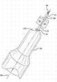
图1是本发明考虑的具有预填充针头(staked needle)的注射器的纵截面。Figure 1 is a longitudinal section of a syringe with a prefilled needle contemplated by the present invention.
图2A、2B和2C是与图1类似的另一实施方案的纵截面的逐渐放大。2A, 2B and 2C are progressively enlarged longitudinal sections of another embodiment similar to FIG. 1 .
图3是与图1类似的另一实施方案的纵截面。FIG. 3 is a longitudinal section of another embodiment similar to FIG. 1 .
图4是显示连接有针头22的柔性隔膜的图示。Figure 4 is a diagram showing the flexible membrane with the
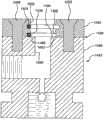
图5是考虑用于形成图1中所示的注射器本体和预填充针头的模具腔和芯的截面图。5 is a cross-sectional view of the mold cavity and core considered for forming the syringe body and prefilled needle shown in FIG. 1 .
图6是显示图5的芯的细节的透视图。FIG. 6 is a perspective view showing details of the core of FIG. 5 .
图7是考虑用于PECVD处理图1的注射器或其它容器的设备的纵截面。图7中特别示出了血液收集管的处理。FIG. 7 is a longitudinal section of an apparatus considered for PECVD processing of the syringe or other container of FIG. 1 . The handling of blood collection tubes is particularly shown in FIG. 7 .
图8是能够代替图7的容器固定器的替代容器固定器的纵截面,Figure 8 is a longitudinal section of an alternative container holder that can replace the container holder of Figure 7,
图9是显示在PECVD处理过程中放在注射器上的临时容器的图示。此处显示了不同类型的注射器,能够代替图1的注射器。Figure 9 is a diagram showing a temporary container placed on a syringe during PECVD processing. A different type of syringe is shown here, which can replace the syringe of Figure 1 .
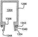
图10显示了临时容器的单独图。Figure 10 shows a separate diagram of the temporary container.
图11显示了双壁容器的纵截面。Figure 11 shows a longitudinal section of a double-walled container.
在本说明书中使用以下附图标记。类似的附图标记表示相似或对应的部件。The following reference numerals are used in this specification. Like reference numerals indicate like or corresponding parts.
发明详述Detailed description of the invention
描述了具有集成针头的注射器。这种构造具有以下任选的优点:减少组装步骤的数量、消除工人在组装过程中对未防护的针头的暴露和/或消除了对用于将针头粘合到注射器上的粘合剂的需求。排除粘合剂潜在地有利于降低可注射药物和注射器之间的相互作用(对于预填充注射器)。A syringe with an integrated needle is described. This configuration has the optional advantage of reducing the number of assembly steps, eliminating worker exposure to unshielded needles during assembly, and/or eliminating the need for adhesives to bond the needle to the syringe . Elimination of adhesives is potentially beneficial in reducing interactions between the injectable drug and the syringe (for prefilled syringes).
参照图1,显示了包括针头22和筒体的注射器20的实施方案。任选地,能够制造帽26以用于注射器20。Referring to Figure 1, an embodiment of a
针头22能够是皮下注射针头(主要区别在于被尖锐化了和以其它方式适于刺穿人体或动物组织)或未尖锐化的针头或喷嘴,其具有外表面32、在一端的输送出口34、在另一端的底座36和从底座36延伸到输送出口34的内部通道38。任选地,针头22的输送出口34能够是尖锐化的或以其它方式变尖的。任意实施方案的针头22能够由导电材料制成。例如,针头22能够由拉制钢制成。
筒体具有限定内腔48的大体为圆柱形的内表面部分40。筒体具有在针头22的外表面32周围模制且与其流体密封接触的前通道44。此实施方案的筒体还具有与其前通道44相邻的大体为半球形的内表面部分42。任选地,针头22的底座36能够与筒体的半球形内表面部分42至少基本齐平。与注射器内表面42(例如注射器20的半球形表面部分42)齐平的针头22能够在针头22和注射器内表面42之间提供平滑过渡。The barrel has a generally cylindrical
筒体能够注塑或以其它方式形成。筒体能够由热塑性材料制成。适合的热塑性材料的几种实例为聚烯烃,例如环烯烃聚合物(COP)、环烯烃共聚物(COC)、聚丙烯或聚乙烯(例如低密度聚乙烯LDPE或高密度聚乙烯HDPE)。筒体还能够由聚对苯二甲酸乙二醇酯(PET)、聚碳酸酯树脂、聚萘(PEN)或任意其它适合的材料制成。任选地,可以选择能够承受真空并在注射器内保持无菌的材料。The barrel can be injection molded or otherwise formed. The barrel can be made of thermoplastic material. A few examples of suitable thermoplastic materials are polyolefins such as cycloolefin polymer (COP), cycloolefin copolymer (COC), polypropylene or polyethylene (eg low density polyethylene LDPE or high density polyethylene HDPE). The cartridge can also be made of polyethylene terephthalate (PET), polycarbonate resin, polynaphthalene (PEN), or any other suitable material. Optionally, a material can be selected that can withstand a vacuum and maintain sterility within the syringe.
在图11中示例的实施方案中,注射器筒体268能够是具有分别由相同或不同材料制成的内壁408和外壁410的双壁容器。这种类型的一种特别实施方案能够由用环烯烃共聚物(COC)模制成的一个壁和由聚酯(例如聚对苯二甲酸乙二醇酯(PET))模制成的另一个壁制成,并在内表面412上具有如前所述的SiOx涂层。如果需要,能够在内壁和外壁之间插入接合涂层或层以促进它们之间的粘合。这种壁结构的优点是能够将具有不同性质的壁结合以形成具有各个壁的各自性质的复合材料。In the embodiment illustrated in FIG. 11 , the
作为一个实例,内壁408能够由在内表面412上的涂覆有SiOx阻隔层的PET制成,外壁410能够由COC制成。在本说明书中别处所示的涂覆有SiOx的PET是优异的氧气阻隔材料,而COC是优异的水蒸气隔离材料,提供了低水蒸气转移速率(WVTR)。这种复合容器能够对氧气和水蒸气都具有优越的阻隔性质。这种结构预期例如用于包含制造时就有的含水试剂且具有长期储藏寿命的预填充注射器,因此其应当具有在其储藏寿命过程中防止通过其复合壁的水蒸气向外传递或氧气或其它气体向内传递的阻隔性质。As an example, the
作为另一实例,内壁408能够由在内表面412上的涂覆有SiOx阻隔层的COC制成,外壁410能够由PET制成。这种结构预期例如用于包含制造时就有的含水无菌流体的预填充注射器。SiOx阻隔层将防止氧气通过其壁进入注射器。COC内壁将防止其它材料(例如水)进出,由此防止含水无菌流体中的水从壁材料中将材料浸出到注射器内。COC内壁还预期防止来自含水无菌流体的水通往注射器外部(由此不适宜地使含水无菌流体变浓),并将防止注射器外部的非无菌水或其它流体通过注射器壁进入并造成内容物变得非无菌。COC内壁还预期可用于降低注射器内壁对柱塞的破坏力或摩擦力。As another example, the
作为另一实例,内表面412能够涂覆有具有总式SiwOxCyHz的涂层,其中w为1,x为0.5-2.4,y为0.6-3,z为2-9。该涂层能够是(i)润滑性涂层,其具有比未涂覆的表面低的摩擦阻力;和/或(i i)疏水涂层,其具有比未涂覆的表面高的疏水性。As anotherexample , the inner surface 412 can be coated with a coating having the general formulaSiwOxCyHz , wherew is 1, x is 0.5-2.4,y is 0.6-3, and z is 2-9. The coating can be (i) a lubricious coating, which has a lower frictional resistance than an uncoated surface; and/or (ii) a hydrophobic coating, which has a higher hydrophobicity than an uncoated surface.
具有由聚合物外层包封的聚合物内层的壁的容器能够通过例如将COC和聚酯树脂层通过同心注射喷嘴引入注射模具中而制成。A container with walls of an inner polymer layer enveloped by an outer polymer layer can be made by, for example, introducing layers of COC and polyester resin into an injection mold through concentric injection nozzles.
图11中所示的具有由聚合物外层包封的聚合物内层的注射器筒体268能够由内向外制成,例如通过在第一模具腔中注塑内壁,然后将芯和模制的内壁从第一模具腔中移除到较大的第二模具腔中,然后在第二模具腔中靠着内壁注塑外壁。任选地,能够在模制的内壁的外表面上提供接合层,然后将外壁外模制到接合层上。A
或者,图11中所示的注射器筒体268能够由外向内制成,例如通过将第一芯插入模制腔中,在磨具腔中注塑外壁,然后将第一芯从模制的第一壁中取出并插入较小的第二芯,然后在仍留在模具腔中的外壁上模制内壁。任选地,能够在模制的外壁的内表面上提供接合层,然后将内壁外模制到接合层上。Alternatively, the
或者,图11中所示的注射器筒体268能够以两步模具中制备。这能够例如通过以下进行:将用于内壁的材料从内喷嘴注塑并将用于外壁的材料从同心的外喷嘴注塑。任选地,能够由设置在内外喷嘴之间的第三同心喷嘴提供接合层。喷嘴能够同时供给各壁材料。一种有用的方法是略微在通过内喷嘴供给内壁材料之前开始通过外喷嘴供给外壁材料。如果存在中间同心喷嘴,那么流动的顺序能够以外喷嘴开始,并按顺序以中间喷嘴继续,然后自内喷嘴。或者,供给的开始顺序能够以与之前描述相反的顺序由内喷嘴开始并向外进行。Alternatively, the
任选地,注射器筒体的横截面的内径和外径(特别是在其后部通道106处)能够基本上为圆形和圆柱形,以便于密封到抽真空设备(例如本说明书中描述的PECVD设备)上。Optionally, the inner and outer diameters of the cross-section of the syringe barrel (particularly at its rear passageway 106) can be substantially circular and cylindrical to facilitate sealing to vacuum evacuation equipment such as those described in this specification PECVD equipment).
任选的帽26配置成将针头22的输送出口34与环境空气50隔离,且能够以另一种方式或进一步保护操作注射器的使用者不会意外被针头刺伤。所示例的帽26包括具有由边缘52限定的开口56的内腔46。在图1中,内腔46基本上完全被注射器20的针头22和锥形鼻状件110填充。开口56的尺寸设定为接收输送出口34。边缘52可在筒体的外部部分54安置。The
在图1的实施方案中,帽26通过常规Luer锁装置固定在注射器20的鼻状件110上就位。注射器的锥形鼻状件110与帽26的相应锥形喉部112相匹配,注射器具有环管114,其具有接收帽26的挡块118和120的内螺纹116以将锥形鼻状件110和喉部112锁定在一起。帽26能够是基本上刚性的。In the embodiment of Fig. 1, the
现在参照图2,显示了注射器筒体122和帽124的变型。在此实施方案中,帽124包括在其底座的柔性唇状密封件72以与筒体122形成防止水分的密封。Referring now to FIG. 2 , a variation of the
在图1和2的实施方案中,任选地,帽26和124能够在PECVD涂覆工艺过程中承受真空。帽26和124能够由LDPE制成。也可以使用可替代的刚性塑料材料,例如聚丙烯。也能够提供额外的密封元件。In the embodiment of Figures 1 and 2, caps 26 and 124 are optionally capable of withstanding a vacuum during the PECVD coating process.
在图3中所示例的另一选择中,帽126是柔性的,且设计成密封在筒体130顶端周围。可变形的材料(例如橡胶或热塑性弹性体(TPE))能够用于帽126。优选的TPE材料包括含氟弹性体,特别是医用级别的含氟弹性体。实例包括

在模制过程中,在某些实施方案中(例如图3中示例的),将少量帽材料132抽取到针头22的顶端或输送出口34中以形成密封。材料132应当具有硬度计以使得将适当量的材料抽取到针头22中并使抽取到针头22中的材料在将其去除时继续粘合到帽126上,不会阻碍针头22的使用。During the molding process, in some embodiments (such as illustrated in FIG. 3 ), a small amount of cap material 132 is drawn into the tip of
在其它实施方案中,能够将帽材料堵塞针头22的输送出口34而不抽取到输送出口34中。对适于实现所需目的的材料的选择在本领域普通技术人员的能力范围内。In other embodiments, the cap material can be blocked from the
能够通过将注射器筒体内形成的底切部134和帽126内的突出件138相结合来产生额外的密封,限定了保持帽126的连接。可替代的实施方案能够包括上述的一种或两种密封。An additional seal can be created by combining an undercut 134 formed within the syringe barrel and a
任选地,参照图2,帽124能够具有底座68和配置成将帽26固定在筒体上的安置位置的连接70。可替代地或除此之外,能够任选地在帽124的底座68处提供柔性唇形密封件72以在将帽124固定在筒体122上时安置在筒体122上。Optionally, referring to FIG. 2 , the
任选地,现在参照图3,在将帽26固定到筒体上时,针头22的输送出口34能够安置在帽126上。这种方法可用于在需要时将输送出口34对空气或其它流体的出入密封。Optionally, referring now to FIG. 3 , the
任选地,连接70能够包括在筒体122和帽124之一上的定位槽或凹槽74和在筒体122和帽124中另一个上的突出件或筋条76,在帽26位于其筒体上的安置位置时,突出件76适配成与定位槽74配合。在一种预期的实施方案中,定位槽74能够在筒体上,而突出件76能够在帽26上。在另一预期的实施方案中,定位槽74能够在帽26上,而突出件76能够在筒体上。在再一预期的实施方案中,第一定位槽74能够在筒体上,且与定位槽74相配合的第一突出件76能够在帽26上,而第二定位槽75能够在帽26上,且相配合的第二突出件77能够在筒体上。通过在模具中加入侧拉伸体(例如92和94),能够将定位槽74作为底切部模制在筒体中。Optionally,
定位槽74与互补的突出件76配合以将帽26组装(卡接)到注射器20上。在这方面,期望帽26具有足够的柔性以允许进行足够的变形以将定位槽74和突出件76卡接接合。
帽(例如26、124和126)能够例如由热塑性材料注塑或以其它方式形成。适合的热塑性材料的几种实例是聚烯烃,例如环烯烃聚合物(COP)、环烯烃共聚物(COC)、聚丙烯或聚乙烯。帽26能够包含热塑性弹性体(TPE)或其它弹性材料或由其制成。帽26还能够由聚对苯二甲酸乙二醇酯(PET)、聚碳酸酯树脂或任意其它适合材料制成。任选地,可以选择能够承受真空和在注射器20内保持无菌的帽26的材料。Caps (eg, 26, 124, and 126) can be injection molded or otherwise formed, for example, from a thermoplastic material. A few examples of suitable thermoplastic materials are polyolefins, such as cycloolefin polymers (COP), cycloolefin copolymers (COC), polypropylene or polyethylene.
任选地,能够在任意帽的实施方案上提供手指夹持部140(图3)以便于容易将帽从注射器上取下并防止意外的针头刺伤。Optionally, a finger grip 140 (Fig. 3) can be provided on any cap embodiment to facilitate easy removal of the cap from the syringe and prevent accidental needle stick injuries.
参照图1,但对任意实施方案都是任选的,能够至少在筒体的半球形内表面部分42上提供阻隔层(有时也称作阻隔涂层)28。任选地,阻隔涂层28在筒体的大体为圆柱形的内表面部分40的至少一部分上延伸。任选地,阻隔涂层28在针头22的底座36和筒体的大体为圆柱形的内表面部分40之间形成阻隔。任选地,阻隔涂层28包含SiOx,其中x为约1.5-约2.9。任选地,阻隔涂层28的厚度为1-100nm。任选地,阻隔涂层28有效提供氧气阻隔。Referring to Figure 1, but optional for any embodiment, a barrier layer (sometimes also referred to as a barrier coating) 28 can be provided on at least the hemispherical inner surface portion 42 of the barrel. Optionally, the
任选地,注射器20预填充有流体58,阻隔涂层28有效地至少减少筒体的材料60浸出到流体58中。阻隔涂层28还能够由于空注射器中以减少最终使用者放入注射器20中的流体的浸出。Optionally,
任选地,除了阻隔涂层28或作为其替代,任意实施方案的注射器20能够在筒体的大体为圆柱形的内表面部分40的至少一部分上具有润滑性涂层30。任选地,润滑性涂层或层30是通过PECVD施加的。“润滑性层”或任意类似的术语通常定义为与未涂覆的表面相比经涂覆的表面的摩擦阻力降低的涂层。如果被涂覆的物体是通常包含柱塞或与涂覆表面滑动接触的可移动部件的注射器(或注射器部件,例如筒体)或任意其它物件,那么摩擦阻力具有两个主要方面—掘起力和柱塞滑动力。Optionally, the
柱塞滑动力试验是柱塞在注射器内的滑动摩擦系数的专门试验,通过将柱塞或其它滑动元件与它们在内滑动的管或其它容器之间的匹配进行标准化,获得通常在平坦表面上测定的与滑动摩擦系数相关的法向力。通常测定的与滑动摩擦系数有关的平行力可与如本说明书中描述测定的柱塞滑动力相当。柱塞滑动力能够如例如ISO7886-1:1993试验中所提供的方式测定。The plunger sliding force test is a specialized test of the sliding coefficient of friction of a plunger within a syringe, obtained by standardizing the fit between a plunger or other sliding element and the tube or other container in which it slides, usually on a flat surface The measured normal force related to the coefficient of sliding friction. The generally measured parallel force related to the coefficient of sliding friction is comparable to the plunger sliding force measured as described in this specification. Plunger sliding force can be determined as provided in, for example, the ISO7886-1:1993 test.
柱塞滑动力试验也能够通过对设备和程序进行适当的变型而适于测量其它类型的摩擦系数,例如将阻挡体(stopper)保持在管内的摩擦。在一种实施方案中,柱塞能够被隔块替代,取出或插入隔块的抽拉力能够作为柱塞滑动力的对应力测定。The plunger sliding force test can also be adapted to measure other types of friction coefficients, such as the friction holding a stopper within a tube, with appropriate modifications to the equipment and procedures. In one embodiment, the plunger can be replaced by a spacer, and the pulling force to remove or insert the spacer can be measured as a relative force to the sliding force of the plunger.
除了柱塞滑动力或作为其替代,能够测量掘起力。掘起力是使静止的柱塞开始在注射器内运动所需的力或使固定的静止阻挡体移开并使其开始运动所需的相应的力。掘起力是通过以下测定的:在柱塞上施加力,该力开始为0或较小的值并逐渐增大直至柱塞开始移动。随着注射器的储存,在将预填充注射器柱塞推离插入或粘附到筒体上的润滑剂之后,由于柱塞和筒体之间的润滑剂的分解,掘起力容易升高。掘起力用以将柱塞断开并使其开始移动所需克服的“粘着”(用于柱塞和筒体之间的粘附的行业术语)所需的力。Breakout force can be measured in addition to or instead of plunger sliding force. Breakout force is the force required to initiate movement of a stationary plunger within a syringe or the corresponding force required to dislodge a stationary stationary barrier and initiate movement. Breakout force is determined by applying a force on the plunger that starts at zero or a small value and increases until the plunger begins to move. As the syringe is stored, the breakout force tends to increase due to the breakdown of the lubricant between the plunger and barrel after the prefilled syringe plunger is pushed away from the lubricant inserted or adhered to the barrel. The breakout force is the force required to overcome the "sticking" (the industry term for the sticking between the plunger and the barrel) to break the plunger and start moving it.
用润滑性层涂覆容器的全部或部分(例如选择性涂覆在与其它部件以滑动方式接触的表面处)的一些功用容易将止块插入或除去或容易使滑动元件(例如柱塞或注射器中的柱塞)通过。通过PECVD施加润滑性层能够避免或减少用喷雾、浸渍或以其它方式施加有机硅或通常以比通过PECVD工艺沉积将会需要的量大得多的量施加的其它润滑剂涂覆容器的需要。Some utility of coating all or part of a container with a lubricious layer (e.g. selectively at surfaces in sliding contact with other parts) facilitates the insertion or removal of stops or eases the sliding of elements such as plungers or syringes. the plunger in) through. Applying the lubricious layer by PECVD can avoid or reduce the need to coat the container with spray, dip or otherwise apply silicone or other lubricants, which are typically applied in much greater quantities than would be required to be deposited by the PECVD process.
涂层优选能够以1-5000nm、或10-1000nm、或10-200nm、或20-100nm的厚度施加到基材上。这种和其它涂层的厚度能够通过例如透射电子显微法(TEM)测定。The coating can preferably be applied to the substrate at a thickness of 1-5000 nm, or 10-1000 nm, or 10-200 nm, or 20-100 nm. The thickness of this and other coatings can be measured by, for example, transmission electron microscopy (TEM).
参照图2,能够沿针头22的底座提供加固纹理以便于在注塑工艺过程中在塑料注射器和针头之间进行良好的结合。例如,任意实施方案的针头22的外表面32能够在前通道44的至少一部分内具有非圆柱形或平坦的部分64以将针头固定在筒体122内。非圆柱形或平坦的部分64任选地可以通过用机床或刀具加工内部为圆柱形的针头坯而提供。非圆柱形或平坦的部分任选地可以通过例如通过将针头坯与另一部件焊接、胶粘或冲压在一起而连接最初分开的非圆柱形或平坦的部分而提供。Referring to Figure 2, a reinforcing texture can be provided along the base of the
任选地,任意实施方案的注射器20能够包括柱塞66,对其尺设定寸和位置以对筒体122的大体为圆柱形的内表面部分40至少基本上密封并沿其移动。如公知的那样,柱塞(例如柱塞66)通常提供用于将流体58通过输送出口34抽吸到筒体122内和/或将流体58从针头22的输送出口34中排出。柱塞(例如66)还能够对筒体122的大体为圆柱形的内表面部分40密封以将注射器中的流体58与环境空气、水分和其它环境材料和条件隔离。Optionally, the
图4是显示另一实施方案的示意图,其中隔膜144(其可替代的能够为限定中心开口的筛网或其它线束图案)支撑部分位于模具腔82内的皮下注射针头22。在模制过程中将线束86插入针头22中以在将筒体模制到针头22上时维持通过针头22的畅通的通道。模制材料能够通过隔膜144各侧的通道插入或可替代地通过隔膜或其它结构144中的开口插入。任选地,隔膜144能够被抓在模制部件中。线束86能够在模制之后可去除,例如通过拉动连接点128,任选地在将模具的一部分相对于另一部分移开时。4 is a schematic diagram showing another embodiment in which a septum 144 (which alternatively can be a mesh or other wire pattern defining a central opening) supports the
参照图1、5和6,此处公开的技术的另一方面是通过将筒体的至少一部分注塑到针头22周围以将针头22固定和密封就位,从而制备具有集成的锚定的针头22的注射器20的方法。将针头22的至少一部分插入模具中,然后注射塑料或其它材料以形成注射器本体。随着塑料在模具腔中冷却,塑料注射器本体结合到针头上,并在针头和注射器之间形成永久结合。针头和注射器之间的结合任选地是防水分的、防液体的、足以维持无菌的且能够承受真空。Referring to Figures 1, 5 and 6, another aspect of the technology disclosed herein is to prepare the
提供具有外表面32、在一端的输送出口34、在另一端的底座36和从底座36延伸到输送出口34的内部通道38的针头22。
提供用于制备筒体的包括模具芯84和模具腔82的模具80。模具80配置成形成的筒体具有限定了内腔48和前通道44的大体为圆柱形的内表面部分40。A mold 80 comprising a
针头22与注射器20的内表面齐平。参见图1。这是通过将针头22定位在模具腔82内将其位于“最低点的”底座36紧邻模具芯84(形成注射器的内腔48)并将其外表面32的至少一部分暴露在模具腔82内而实现的。模具芯84任选地可以调节以补偿模制材料的收缩,例如通过添加针头支撑凸起件(例如销钉142)。凸起件142位于芯的顶部,在此处芯接触针头的底部,以将针头向上位移(参照图中的针头方向),且尺寸能够调节(例如通过研磨)以将其放在在模制材料收缩之后将与筒体的半球形表面42齐平的位置处。The
然后通过以下注塑筒体:将可模制材料60注入模具腔82中,在针头22外表面32暴露于模具腔82内的部分形成筒体的限定前开口的部分,以将筒体与针头22连接。注意图5和6是示意图。本领域技术人员能够提供进一步的细节,例如可将注射器本体24从模具80中释放出的分模线和多部件模具80。The barrel is then injection molded by injecting the moldable material 60 into the
任选地,在模制过程中能够通过用具有第一和第二端88和90的柔性线束86穿过针头22的内部通道38而将针头22固定就位并保持没有模制材料。线束86能够使适合材料(不限于制备其的材料)的任一个或多个细丝或杆。对于几种非限制实例,线束86能够是金属线、碳纤维或玻璃纤维。线束材料优选具有远高于模制温度的熔化或玻璃态转化温度。能够将线束加入磨具腔82或芯84中,延伸到针头22中,并在形成筒体之后固定到内部通道38的外部就位。脱出和除去模具80将线束86从针头中拉出。Optionally, the
在将可模制材料60注入模具腔82中之前,能够将线束86穿到内部通道38中。也能够将线束86穿到针头22的内部通道38的一部分中。例如,能够将线束86穿到与底座36相邻的内部通道38的一部分中。对于另一实施例,能够将线束86穿到与输送出口34相邻的内部通道38的一部分中。The
任选地,线束86的第一端88固定到模具芯84。任选地,线束86的第二端90也或作为替换固定到模具腔82。Optionally, a
任选地,通过提供与模具腔82相关联的至少一个侧拉伸体92或94并紧邻将要暴露于最终制成的注射器20中的针头22的外表面的一部分而能够使针头22在模制步骤过程中保持没有模制材料。侧拉伸体92能够配置和定位以保持筒体材料60远离针头22的外表面32的紧邻部分。能够在将可模制材料60注入模具腔82中之前提供侧拉伸体(此处是一对侧拉伸体92和94)并将其移动就位。任选地,能够使用至少一个侧拉伸体92或94或此处使用两者以将针头22定位在模具80中。侧拉伸体还能用于形成定位槽74。侧拉伸体的分模线应当在非关键区域中,优选在固定夹具和柔性唇形件之间,如图2中所示,但也能够位于远离帽26的这些部分的其它区域中。Optionally,
任选地,帽26能够外模制在注射器20上。在一种实施方案中,帽26能够配置成将针头22的输送出口34与环境空气50隔离。在实施方案中,帽26能够外模制以至少与针头22的输送出口34接触。在实施方案中,帽26能够由热塑性弹性体外模制。Optionally,
在图2中所示但可适用于任意实施方案的另一选择中,帽26能够包括内部部分96和外部部分98。内部部分96能够模制成不与筒体接触。内部部分96能够与筒体组装。将内部部分96固定就位,能够在帽26的内部部分96上外模制限定帽26的外部部分98的额外树脂。任选地,帽26的外部和内部部分98和96能够通过外模制集成连接。In another option, shown in FIG. 2 but applicable to any embodiment, the
任选地,预期了两步注塑工艺。第一步能够通过将可模制材料60注入模具空腔82中形成具有锚定的针头22的筒体而进行。第二步能够通过在注射器20上外模制帽26而进行。在模制过程中帽的收缩能够用于增强其在注射器20上的密封。Optionally, a two-step injection molding process is contemplated. The first step can be performed by injecting moldable material 60 into
另一种两步方案能够通过在第一步通过中形成帽26并在第二步中形成注射器筒体而进行。在这种方案中,能够在第一步之前将针头22插入模具腔82中,在第一步中能够将帽26模制在包括输送出口34的针头22的一部分周围,刚模制好的帽26能够将针头22定位在模具腔82中并在第二步中模制筒体时暴露针头的底座36。Another two-step approach can be performed by forming the
可替代地,能够使用一步模制工艺制备没有帽的单独的注射器20。如果需要,然后能够单独制备帽。一步模制工艺特别适用于具有较小针头的注射器,例如用于胰岛素给药。Alternatively, a
在将筒体和针头22相结合之后,能够对筒体进行等离子体处理。示例的具有预组装针头22的注射器20的设计便于使用PECVD工艺涂覆筒体的内表面,例如40和42。对于本发明的这一方面,针头22可替代地能够方便地预组装,例如通过胶粘到注射器中,代替模制工艺中的锚定(staking)。注射器20中的以下设计要素预期有利于进行有效的PECVD涂覆。首先,常规筒体的针头端处的“毛细管区域”能够减少或除去,例如通过使针头22的底座36与筒体的半球形表面部分42齐平。常规注射器的毛细管区域具有比筒体小得多的直径。涂覆常规注射器的毛细管区域是困难的。与常规毛细管区域相反,筒体的半球形表面部分42容易使用通常改造以适于涂覆常规圆底医用样品收集管(有时称作试管)的内壁的类型的PECVD设备涂覆。After combining the barrel and
在某些实施方案中,在用PECVD涂覆筒体的内表面部分40和42之前将帽26组装在注射器20上也是有用的。帽26能够用于在PECVD过程中将注射器20的针头端(更准确地说是针头22内径处的输送出口34)对环境空气密封或隔离。这种方法能够用于在不将注射器20放入单独的真空腔中之前在注射器20中抽真空以实施PECVD涂覆。In certain embodiments, it is also useful to assemble the
图7-10总体示例了适用于用PECVD涂覆容器内壁(例如注射器筒体的内表面部分40和42)的设备。7-10 generally illustrate an apparatus suitable for PECVD coating the interior walls of containers, such as the
图7显示了具有配置成接收和安置容器180的开口(例如图1的注射器20的后开口106)的容器端口182的容器夹持装置1150(即用容器180取代图1的筒体,其中针头22和帽26不变,并通过例如提供U形截面的隧道式电极1160来配置电极1160以使注射器筒体和附带的针头22和帽26与电极1160紧密相邻)。7 shows a
安置的容器180和24的内表面能够经容器端口182处理。容器夹持装置1150能够包括用于将气体从安置在容器端口192上的容器180中抽出的管道(例如真空管道1194)。容器夹持装置能够包括第二端口,例如在真空管道194和外部真空源(例如真空泵198)之间连通的真空端口196。容器端口192和真空端口196能够具有密封元件,例如O形环对接封头(分别为1100和1102)或在容器端口182的圆柱形内壁或外壁和容器180的圆柱形内壁或外壁之间的侧部密封件以接收并形成与容器180或外部真空源198的密封,同时允许通过该端口的连通。也能够使用垫圈或其它密封设施。The interior surfaces of the mounted
容器夹持装置(例如1150)能够由任意材料制成,例如热塑性材料和/或不导电的材料。或者,容器夹持装置(例如1150)能够部分或甚至主要由导电材料制成并朝向不导电材料(例如在由容器端口192、真空管道194和真空端口196限定的通道中)。适用于容器夹持装置1150的实例为:聚缩醛,例如E.I.du Pont De Nemours and Company,Wilmington,Delaware销售的

图7还示例了容器夹持装置(例如1150)能够具有用于在将容器180接近或安置在端口192上时将容器180居中的环管1116。FIG. 7 also illustrates that a vessel holding device (eg, 1150 ) can have
图8是特别适于接收容器(例如如图1中示例的具有管状后开口106的注射器20)的容器夹持装置1482的可替代结构。容器夹持装置1482包括在接头1488处连接在一起的上部部分1484和底座1486。将密封元件(例如O形环1490)(将其右侧切掉以使将其保持的囊得以被描述)接头1488处在上部部分1484和底座1486之间被抓住。在示例的实施方案中,O形环1490接收在环形囊1492中以在将上部部分1484连接到底座1486上时定位O形环。FIG. 8 is an alternative configuration of a
在此实施方案中,在将上部部分1484和底座1486连接(在此例中通过螺钉1498和1500连接)时,O形环1490被抓住并靠在径向延伸的支柱表面1494和部分限定囊1492的径向延伸的壁1486上。由此O形环1490安置在上部部分1484和底座1486之间。在上部部分1484和底座1486之间夹持的O形环1490还接收容器180(在此图中除去以便于清楚示例其它特征)并在容器180开口周围形成容器端口1502的第一O形环密封。In this embodiment, when
在此实施方案中,尽管不是必须,但容器端口1502具有第一O形环1490密封和轴向间隔的第二O形环1504密封,其各自设定尺寸以接收容器(例如180)的外径以在容器端口1502和容器(例如180)之间形成密封。O形环1490和1504之间的间隔为容器(例如180)在两个轴向间隔的点之间提供支撑,防止容器(例如180)相对于O形环1490和1504或容器端口1502歪斜。在此实施方案中,尽管不是必须,径向延伸的支柱表面1494位于O形环1490和1506密封的附近并围绕真空管道1508。In this embodiment, although not required, the
帽26能够直接密封针头22的输送出口34。如本说明书中所解释的,至少帽26中与输送出口34相邻的部分是TPE,其在针头的端部压缩并在形成密封(柔性帽实施方案)。或者帽能够置于针头22之上并沿注射器20密封。在此实施方案中,可能是有用的是,帽是或包括基本上为刚性的外壳以承受由真空产生的形变。The
任选地,如图1中所示,在进行PECVD之前,能够将装配有配合的Luer连接且适于在使用前保护针头22的永久帽26安装在注射器20上的针头22之上。在该工艺的另一变型中,能够将特定的帽放在注射器上用于辅助PECVD,且为了注射器20的后续操作和使用任选地用常规帽代替。Optionally, as shown in FIG. 1 , a
能够通过以下对筒体进行等离子体处理(例如利用PECVD):在筒体的内腔48内形成等离子体100;将有机硅气体102引入筒体的内腔48内;并在筒体的大体为圆柱形的内表面部分40和大体为半球形的内表面部分42中的至少一个上沉积非气态有机硅材料的涂层28或30。使用等离子体处理或其它方法,能够在针头22的底座36和筒体之间沉积非气态的有机硅材料的涂层28或30。The barrel can be plasma treated (eg, using PECVD) by: forming a plasma 100 within the
用于本发明的PECVD涂层的前体宽泛地限定为有机金属前体。有机金属前体在本说明书中限定为包含具有有机残基(例如烃、氨基碳或氧碳残基)的来自周期表第III和/或第IV族的金属元素的化合物。如前限定的有机金属化合物包括具有直接连接到硅或其它III/IV族金属原子上或任选地通过氧或氮原子连接的有机部分的任何前体。周期表第III族的有关元素为硼、铝、镓、铟、铊、钪、钇和镧,优选铝和硼。周期表第IV族的有关元素为硅、锗、锡、铅、钛、锆、铪和钍,优选硅和锡。也能够预期其它挥发性有机化合物。然而,有机硅化合物优选用于实施本发明。Precursors for PECVD coatings of the present invention are broadly defined as organometallic precursors. Organometallic precursors are defined in this specification as compounds comprising metal elements from Groups III and/or IV of the Periodic Table having organic residues such as hydrocarbon, aminocarbon or oxycarbon residues. Organometallic compounds as previously defined include any precursor having an organic moiety attached directly to a silicon or other Group III/IV metal atom or optionally via an oxygen or nitrogen atom. Relevant elements of group III of the periodic table are boron, aluminum, gallium, indium, thallium, scandium, yttrium and lanthanum, preferably aluminum and boron. Relevant elements of group IV of the periodic table are silicon, germanium, tin, lead, titanium, zirconium, hafnium and thorium, preferably silicon and tin. Other volatile organic compounds are also contemplated. However, organosilicon compounds are preferred for use in the practice of the invention.
预期有机硅前体,其中“有机硅前体”在整个说明书中最宽泛地定义为具有以下链中的至少一个的化合物:Organosilicon precursors are contemplated, where "organosilicon precursor" is defined broadly throughout the specification as a compound having at least one of the following chains:

或or

上述第一结构是连接到氧原子和有机碳原子(有机碳原子是与至少一个氢原子连接的碳原子)的四价硅原子。上述第二结构是连接到-NH-连接基和有机碳原子(有机碳原子是与至少一个氢原子连接的碳原子)的四价硅原子。任选地,有机硅前体选自由以下构成的组:线性硅氧烷、单环硅氧烷、多环硅氧烷、聚倍半硅氧烷、线性硅氮烷、单环硅氮烷、多环硅氮烷、聚倍半硅氮烷以及这些前体中任意两种或更多种的组合。还预期烷基三甲氧基硅烷作为前体,尽管不再上述两式之内。The above-mentioned first structure is a tetravalent silicon atom bonded to an oxygen atom and an organic carbon atom (an organic carbon atom is a carbon atom bonded to at least one hydrogen atom). The second structure described above is a tetravalent silicon atom attached to an -NH- linker and an organic carbon atom (an organic carbon atom is a carbon atom attached to at least one hydrogen atom). Optionally, the organosilicon precursor is selected from the group consisting of linear siloxanes, monocyclic siloxanes, polycyclic siloxanes, polysilsesquioxanes, linear silazanes, monocyclic silazanes, Polycyclic silazanes, polysilsesquiazanes, and combinations of any two or more of these precursors. Alkyltrimethoxysilanes are also contemplated as precursors, although not within the above two formulas.
特别地,有机硅前体是单环硅氧烷,优选OMCTS。In particular, the organosilicon precursor is a monocyclic siloxane, preferably OMCTS.
如上所述,有机硅前体还能够是线性硅氧烷,优选HMDSO。如果使用含氧前体(例如硅氧烷),那么在形成疏水或润滑性涂层条件下由PECVD得到的代表性的经验预测组成将会是在定义部分中定义的SiwOxCyHz,而在形成阻隔涂层的条件下由PECVD得到的代表性的经验预测组成将会是SiOx,其中在该式中x为约1.5-约2.9。如果使用含氮前体(例如硅氮烷),预测组成将会是SiwNxCyHz,即在定义部分中指定的SiwOxCyHz中,O被N替代,且价数适配成与O相比N的更高价态(3代替2)。后一种适配通常将使硅氧烷中的w、x、y和z遵循其氮杂对应物中相应的价数。在本发明的特别方面中,Siw*Nx*Cy*Hz*,其中w*、x*、y*和z*与对于硅氧烷对应物的w、x、y和z具有相同的定义,但在氢原子数上具有任选的差别。As mentioned above, the organosilicon precursor can also be a linear siloxane, preferably HMDSO. If oxygen-containing precursors (e.g. siloxanes) are used, then a representative empirically predicted composition from PECVD under conditions to form hydrophobic or lubricious coatings would be Siw Ox Cy H as defined in the Definitions sectionz , while a representative empirically predicted composition from PECVD under conditions to form a barrier coating would be SiOx , where x in this formula ranges from about 1.5 to about 2.9. If a nitrogen-containing precursor (e.g. silazane) is used, the predicted composition will be Siw Nx Cy Hz , i.e., in Siw Ox Cy Hz specified in the definitions section, O is replaced by N, and The valence number was adapted to a higher valence state of N compared to O (3 instead of 2). The latter adaptation will generally cause w, x, y, and z in the siloxane to follow the corresponding valences in its aza counterpart. In a particular aspect of the invention, Siw* Nx* Cy* Hz* , where w*, x*, y* and z* have the same w, x, y and z as for the siloxane counterpart but with an optional difference in the number of hydrogen atoms.
具有上述经验式的一种前体原料是线性硅氧烷,例如具有下式的材料:One precursor material having the above empirical formula is a linear siloxane, such as a material having the formula:
其中各R独立地选自烷基,例如甲基、乙基、丙基、异丙基、丁基、异丁基、叔丁基、乙烯基、炔或其它,n为1、2、3、4或更大,任选地为2或更大。预期的线性硅氧烷的几种实例为:Wherein each R is independently selected from alkyl, such as methyl, ethyl, propyl, isopropyl, butyl, isobutyl, tert-butyl, vinyl, alkyne or others, n is 1, 2, 3, 4 or greater, optionally 2 or greater. A few examples of contemplated linear siloxanes are:
六甲基二硅氧烷(HMDSO)、Hexamethyldisiloxane (HMDSO),
八甲基三硅氧烷、Octamethyltrisiloxane,
十甲基四硅氧烷、Decamethyltetrasiloxane,
十二甲基五硅氧烷、Dodecamethylpentasiloxane,
或这些中两种或多种的组合。其中在以上结构中用-NH-替代氧原子的类似的硅氮烷也可用于制备类似的涂层。预期的线性硅氮烷的几种实例为八甲基三硅氮烷、十甲基四硅氮烷或这些中两种或更多种的组合。or a combination of two or more of these. Similar silazanes in which -NH- is substituted for the oxygen atom in the above structure can also be used to prepare similar coatings. A few examples of contemplated linear silazanes are octamethyltrisilazane, decamethyltetrasilazane, or combinations of two or more of these.
V.C.另一种前体原料是单环硅氧烷(例如具有以下结构式的材料)或类似的单环硅氮烷:Another precursor material for V.C. is a monocyclic siloxane (such as a material having the following formula) or a similar monocyclic silazane:
其中R与线性结构中的定义相同,“a”是3-约10。预期的杂取代或未取代的单环硅氧烷和硅氮烷的几种实例包括:wherein R is as defined in the linear structure and "a" is from 3 to about 10. Several examples of contemplated heterosubstituted or unsubstituted monocyclic siloxanes and silazanes include:
1,3,5-三甲基-1,3,5-三[(3,3,3-三氟丙基)甲基]环三硅氧烷、1,3,5-Trimethyl-1,3,5-tris[(3,3,3-trifluoropropyl)methyl]cyclotrisiloxane,
2,4,6,8-四甲基-2,4,6,8-四乙烯基环四硅氧烷、2,4,6,8-Tetramethyl-2,4,6,8-tetravinylcyclotetrasiloxane,
五甲基环五硅氧烷、Pentamethylcyclopentasiloxane,
五乙烯基五甲基环五硅氧烷、Pentavinylpentamethylcyclopentasiloxane,
六甲基环三硅氧烷、Hexamethylcyclotrisiloxane,
六苯基环三硅氧烷、Hexaphenylcyclotrisiloxane,
八甲基环四硅氧烷(OMCTS)、Octamethylcyclotetrasiloxane (OMCTS),
八苯基环四硅氧烷、Octaphenylcyclotetrasiloxane,
十甲基环五硅氧烷、Decamethylcyclopentasiloxane,
十二甲基环六硅氧烷、Dodecamethylcyclohexasiloxane,
甲基(3,3,3-三氟丙基)环硅氧烷,Methyl(3,3,3-trifluoropropyl)cyclosiloxane,
还预期了环状有机硅氮烷,例如:Cyclic organosilazanes are also contemplated, such as:
八甲基环四硅氮烷、Octamethylcyclotetrasilazane,
1,3,5,7-四乙烯基-1,3,5,7-四甲基环四硅氮烷、1,3,5,7-tetravinyl-1,3,5,7-tetramethylcyclotetrasilazane,
六甲基环三硅氮烷、Hexamethylcyclotrisilazane,
八甲基环四硅氮烷、Octamethylcyclotetrasilazane,
十甲基环五硅氮烷、Decamethylcyclopentasilazane,
十二甲基环六硅氮烷、或dodecamethylcyclohexasiazane, or
这些中任意两种或更多种的组合。A combination of any two or more of these.
V.C.另一种前体原料是多环硅氧烷,例如具有以下结构式之一的材料:Another precursor material for V.C. is a polycyclic siloxane, such as a material having one of the following formulas:

其中Y可以是氧或氮,E是硅,Z是氢原子或有机取代基,例如烷基,例如甲基、乙基、丙基、异丙基、丁基、异丁基、叔丁基、乙烯基、炔基或其它。当Y是氧时,各单元从左到右分别是硅三环(s ilatrane)、准硅三环(silquasilatrane)和半硅三环(siproatrane)。当Y是氮时,各结构为氮杂硅三环(azasilatrane)、氮杂准硅三环(azasilquasilatrane)和氮杂半硅三环(azasiproatrane)。wherein Y can be oxygen or nitrogen, E is silicon, and Z is a hydrogen atom or an organic substituent, such as an alkyl group, such as methyl, ethyl, propyl, isopropyl, butyl, isobutyl, tert-butyl, Vinyl, alkynyl or others. When Y is oxygen, the units from left to right are silatrane, quasi-silicon tricycle (silquasilatrane) and semi-silicon tricycle (siproatrane). When Y is nitrogen, the respective structures are azasilatrane, azasilquasilatrane, and azasiproatrane.
VC.另一种多环硅氧烷前体原料是聚倍半硅氧烷,经验式为RSiO1.5,结构式为:VC. Another polycyclic siloxane precursor raw material is polysilsesquioxane, the empirical formula is RSiO1.5 , and the structural formula is:
T8立方体T8 cube
其中各R是氢原子或有机取代基,例如烷基,例如甲基、乙基、丙基、异丙基、丁基、异丁基、叔丁基、乙烯基、炔或其它。这种类型的两种商品材料是:SST-eM01聚(甲基倍半硅氧烷),其中各R是甲基;和SST-3MH1.1聚(甲基-氢倍半硅氧烷)(poly(hydridosilsesquioxane)),其中90%的R基团是甲基,10%是氢原子。该材料例如可以在四氢呋喃中的10%溶液得到。还预期了这些中两种或更多种的组合。其它预期前体的实例是甲基硅三环,CAS编号2288-13-3,其中各Y是氧,Z是甲基;甲基氮杂硅三环,SST-eM01聚(甲基倍半硅氧烷),其中各R任选地可以是甲基;SST-3MH1.1聚(甲基-氢倍半硅氧烷),其中90%的R基团是甲基,10%是氢原子;或这些中任意两种或更多种的组合。wherein each R is a hydrogen atom or an organic substituent such as an alkyl group such as methyl, ethyl, propyl, isopropyl, butyl, isobutyl, tert-butyl, vinyl, alkyne or others. Two commercial materials of this type are: SST-eM01 poly(methylsilsesquioxane), where each R is methyl; and SST-3MH1.1 poly(methyl-hydrogensilsesquioxane) ( poly(hydridosilsesquioxane)), in which 90% of the R groups are methyl groups and 10% are hydrogen atoms. This material is available, for example, as a 10% solution in tetrahydrofuran. Combinations of two or more of these are also contemplated. Examples of other contemplated precursors are methylsilyltricyclo, CAS No. 2288-13-3, wherein each Y is oxygen and Z is methyl; methylazasilyltricyclo, SST-eM01 poly(methylsilsesquisil oxane), wherein each R optionally can be a methyl group; SST-3MH1.1 poly(methyl-hydrogen silsesquioxane), wherein 90% of the R groups are methyl groups and 10% are hydrogen atoms; or a combination of any two or more of these.
VC.其中用-NH-替代上述结构中的氧原子的类似的聚倍半硅氮烷也可用于制备类似的涂层。预期的聚倍半硅氮烷的实例是聚(甲基倍半硅氮烷),其中各R是甲基;和聚(甲基-氢倍半硅氮烷),其中90%的R基团是甲基,10%是氢原子。还预期了这些中两种或更多种的组合。VC. Similar polysilsesquiazanes in which the oxygen atoms in the above structures are replaced by -NH- can also be used to prepare similar coatings. Examples of contemplated polysilsesquiazanes are poly(methylsilsesquiazanes), wherein each R is a methyl group; and poly(methyl-hydrogensilsesquiazanes), wherein 90% of the R groups It is a methyl group, and 10% is a hydrogen atom. Combinations of two or more of these are also contemplated.
VC.一种特别预期的用于依照本发明的润滑性层的前体是单环硅氧烷,例如是八甲基环四硅氧烷。VC. A particularly contemplated precursor for the lubricity layer according to the invention is a monocyclic siloxane, for example octamethylcyclotetrasiloxane.
一种特别预期的用于依照本发明的疏水层的前体是单环硅氧烷,例如是八甲基环四硅氧烷。A particularly contemplated precursor for the hydrophobic layer according to the invention is a monocyclic siloxane, for example octamethylcyclotetrasiloxane.
一种特别预期的用于依照本发明的阻隔涂层的前体是线性硅氧烷,例如HMDSO。One particularly contemplated precursor for barrier coatings according to the invention is a linear siloxane, such as HMDSO.
VC.在依照本发明的任意涂覆方法中,施加步骤任选地可以通过蒸发前体和将其提供在基材附近而进行。例如,通常通过将其加热到50℃而使OMCTS挥发,然后将其施加到PECVD设备中。VC. In any coating method according to the invention, the step of applying may optionally be carried out by evaporating the precursor and providing it in the vicinity of the substrate. For example, OMCTS is typically volatilized by heating it to 50°C before applying it to a PECVD apparatus.
V.2总体PECVD方法V.2 Overall PECVD method
在本发明的上下文中,通常应用以下PECVD方法,其包含以下步骤:In the context of the present invention, the following PECVD method is generally applied, comprising the following steps:
(a)在基材表面的附近提供包含此处限定的前体、任选的有机硅前体和任选的O2的气态反应物;和(a) providing a gaseous reactant comprising a precursor as defined herein, an optional organosilicon precursor, andoptional O in the vicinity of the substrate surface; and
(b)由气态反应物产生等离子体,由此通过等离子体增强的化学气相沉积法(PECVD)在基材表面上形成涂层。(b) Plasma is generated from gaseous reactants, thereby forming a coating on the surface of the substrate by plasma enhanced chemical vapor deposition (PECVD).
在该方法中,涂层特性有利地由以下条件中的一种或多种设定:等离子体性质、施加等离子体的压力、施加以产生等离子体的电源、气态反应物中O2的存在和相对量、等离子体体积和有机硅前体。任选地,涂层特性是由气态反应物中O2的存在和相对量和/或施加以产生等离子体的电源所设定。In this method, the coating properties are advantageously set by one or more of the following conditions: plasma properties, the pressure at which the plasma is applied, the power source applied to generate the plasma, the presence ofO2 in the gaseous reactants and Relative amounts, plasma volumes, and organosilicon precursors. Optionally, the coating properties are set by the presence and relative amount ofO2 in the gaseous reactants and/or the power applied to generate the plasma.
在本发明的所有实施方案中,在任选的方面中,等离子体是非中空阴极等离子体。In all embodiments of the invention, in optional aspects, the plasma is a non-hollow cathode plasma.
在进一步优选的方面中,等离子体是在减压条件下(与常压或大气压相比)产生的。任选地,减压为小于300毫托,任选地小于200毫托,甚至任选地小于100毫托。In a further preferred aspect, the plasma is generated under reduced pressure (compared to normal or atmospheric pressure). Optionally, the reduced pressure is less than 300 mTorr, optionally less than 200 mTorr, even optionally less than 100 mTorr.
PECVD任选地是通过用以微波或无线电频率(任选地以无线电频率)供电的电极使包含前体的气态反应物激发而进行的。用于实施本发明的实施方案的无线电频率也将称作“RF频率”。典型的用于实施本发明的无线电频率是10kHz-小于300MHz,任选地为1-52MHz,甚至任选地为10-15MHz的频率。最优选13.56MHz的频率,这是进行PECVD作业的政府批准频率。PECVD is optionally performed by exciting gaseous reactants comprising precursors with electrodes powered at microwave or radio frequency, optionally at radio frequency. Radio frequencies used to implement embodiments of the present invention will also be referred to as "RF frequencies". Typical radio frequencies for practicing the invention are frequencies from 10 kHz to less than 300 MHz, optionally 1-52 MHz, even optionally 10-15 MHz. Most preferred is a frequency of 13.56 MHz, which is the government-approved frequency for PECVD operations.
使用RF电源与微波源相比有几个优点:由于RF在较低的功率操作,因此对基材/容器的加热较少。因为本发明的关注点在于等离子体涂层施加在塑料材料上,因此较低的处理温度适于防止基材的熔化/变形。在使用微波PECVD时为了防止基材过热,通过使功率脉冲将微波PECVD短脉冲施加。功率脉冲延长了涂覆的循环时间,这在本发明中是不适宜的。较高频率的微波还能够造成挥发性物质(例如塑料基材中残余的水、低聚物和其它材料)的除气(也称作脱气)。这种除气能够影响PECVD涂层。使用微波进行PECVD的主要关注是涂层从基材分层。由于微波在沉积涂层之前改变了基材表面,因此会发生分层。为了减轻分层的可能性,对于微波PECVD已经开发了界面涂层以实现涂层和基材之间良好的结合。对于RF PECVD必须要这种界面涂层,因为没有分层的风险。最后,使用较低的功率有利地施加依照本发明的润滑性层和疏水层。与微波功率相比,RF功率以较低的功率操作比对PECVD工艺提供更好地控制。然而,微波功率(尽管不是那么优选的)也可在适合的工艺条件下使用。Using an RF power source has several advantages over a microwave source: Since RF operates at lower power, there is less heating of the substrate/container. Since the focus of the present invention is the application of plasma coatings on plastic materials, lower processing temperatures are suitable to prevent melting/deformation of the substrate. To prevent overheating of the substrate when microwave PECVD is used, microwave PECVD is applied in short pulses by pulsing the power. Power pulsing prolongs the coating cycle time, which is undesirable in the present invention. Higher frequency microwaves can also cause outgassing (also known as outgassing) of volatile species such as residual water, oligomers, and other materials in the plastic substrate. This outgassing can affect PECVD coatings. The main concern with PECVD using microwaves is the delamination of the coating from the substrate. Delamination occurs because the microwaves alter the surface of the substrate before the coating is deposited. To mitigate the possibility of delamination, interfacial coatings have been developed for microwave PECVD to achieve a good bond between the coating and the substrate. This interfacial coating is necessary for RF PECVD because there is no risk of delamination. Finally, the lubricious and hydrophobic layers according to the invention are advantageously applied using lower power. Compared to microwave power, RF power provides better control over the PECVD process at lower power operation. However, microwave power (although less preferred) can also be used under suitable process conditions.
进一步地,对于此处描述的所有PECVD方法,在用于产生等离子体的功率(以瓦特计)与在其中产生等离子体的内腔的体积之间存在特定的关联。通常,内腔是依照本发明涂覆的容器的内腔。如果使用相同的电极系统,RF功率将随容器的体积按比例变化。一旦气态反应物的组成(例如前体与O2的比例)和PECVD涂覆方法中除功率之外的所有其它参数都已设定,在容器的几何形状保持不变仅其体积改变时,其通常将不会变化。在这种情况下,功率将与体积成正比。因此,由本说明书提供的功率体积比开始,能够容易地找到必须施加以在相同几何形状但不同尺寸的容器中得到相同或相似涂层所需的功率。容器几何形状对施加功率的影响由对于管子的实施例与注射器筒体的实施例相比的结果所示例。Further, for all PECVD methods described here, there is a specific correlation between the power (in watts) used to generate the plasma and the volume of the internal cavity in which the plasma is generated. Typically, the lumen is the lumen of a container coated in accordance with the invention. If the same electrode system is used, the RF power will scale proportionally with the volume of the vessel. Once the composition of the gaseous reactants (e.g. the ratio of precursor toO2 ) and all other parameters in the PECVD coating process except the power have been set, its Normally there will be no change. In this case power will be directly proportional to volume. Thus, starting from the power-to-volume ratios provided by this specification, it is easy to find the power that must be applied to obtain the same or similar coatings in containers of the same geometry but different sizes. The effect of container geometry on applied power is exemplified by the results for the tube embodiment compared to the syringe barrel embodiment.
对于本发明的任意涂层,用以足以在基材表面上形成涂层的功率供电的电极产生等离子体。For any coating of the invention, the plasma is generated with electrodes powered with a power sufficient to form the coating on the surface of the substrate.
对于氧气阻隔层,在依照本发明的实施方案的方法中,等离子体任选地是由以下产生的:For oxygen barrier layers, in methods according to embodiments of the present invention, the plasma is optionally generated by:
(i)用例如8-500W(例如任选地10-400W,任选地20-350W,任选地25-300W,任选地25-50W)的电功率供电的电极;和/或(i i)其中电极功率与等离子体体积的比例小于10W/ml,任选地5W/ml-0.1W/ml,任选地4W/ml-0.1W/ml,任选地2W/ml-0.2W/ml。and/or ) wherein the ratio of electrode power to plasma volume is less than 10W/ml, optionally 5W/ml-0.1W/ml, optionally 4W/ml-0.1W/ml, optionally 2W/ml-0.2W/ml .
(ii)电极功率与等离子体体积的比例等于或大于5W/ml,任选地6W/ml-150W/ml,任选地7W/ml-100W/ml,任选地7W/ml-20W/ml。(ii) The ratio of electrode power to plasma volume is equal to or greater than 5W/ml, optionally 6W/ml-150W/ml, optionally 7W/ml-100W/ml, optionally 7W/ml-20W/ml .
对于润滑性层或疏水层,在依照本发明的实施方案的方法中,等离子体任选地是由以下产生的:For a lubricious layer or a hydrophobic layer, in methods according to embodiments of the invention, the plasma is optionally generated by:
(i)用足以在基材表面上形成层的功率供电的电极,电功率为0.1-25W,任选地1-22W,任选地3-17W,甚至任选地5-14W,任选地7-11W,任选地8W;和/或(i) an electrode powered with a power sufficient to form a layer on the surface of the substrate, the electrical power is 0.1-25W, optionally 1-22W, optionally 3-17W, even optionally 5-14W, optionally 7 - 11W, optionally 8W; and/or
(i i)电极功率与等离子体体积的比例小于10W/ml,任选地5W/ml-0.1W/ml,任选地4W/ml-0.1W/ml,任选地2W/ml-0.2W/ml。(ii) The ratio of electrode power to plasma volume is less than 10W/ml, optionally 5W/ml-0.1W/ml, optionally 4W/ml-0.1W/ml, optionally 2W/ml-0.2W /ml.
容器的几何形状也能影响用于PECVD涂层所有的气体入口的选择。在特别方面中,注射器能够用敞开的管入口涂覆,管子能够用具有延伸到管子中的小的开孔的气体入口涂覆。Vessel geometry can also affect the choice of all gas inlets for PECVD coating. In a particular aspect, the syringe can be coated with an open tube inlet and the tube can be coated with a gas inlet with a small opening extending into the tube.
用于PECVD的功率(以瓦特计)还对涂层性质具有影响。通常,功率的升高将提高涂层的阻隔性质,功率的降低将提高涂层的润滑性和疏水性。例如,对于在具有约3ml的体积的筒体的内壁上的涂层,高于30W的功率将得到主要是阻隔涂层的涂层,而小于30W的功率将得到主要是润滑性层的涂层(参见实施例)。The power (in watts) used for PECVD also has an effect on the coating properties. Generally, an increase in power will increase the barrier properties of the coating, and a decrease in power will increase the lubricity and hydrophobicity of the coating. For example, for a coating on the inner wall of a cylinder having a volume of about 3ml, a power above 30W will result in a coating that is primarily a barrier coating, while a power below 30W will result in a coating that is primarily a lubricious layer (see examples).
决定涂层性质的进一步的参数是用于产生等离子体的气态反应物中O2(或另一氧化剂)与前体(例如有机硅前体)的比例。通常,气态反应物中O2比例的升高将提高涂层的阻隔性质,O2比例的降低将提高涂层的润滑性和疏水性。A further parameter determining the properties of the coating is the ratio ofO2 (or another oxidizing agent) to precursor (eg organosilicon precursor) in the gaseous reactants used to generate the plasma. Generally, an increase in the proportion ofO2 in the gaseous reactant will improve the barrier properties of the coating, and a decrease in the proportion ofO2 will increase the lubricity and hydrophobicity of the coating.
如果需要润滑性层,则O2的含量与气态反应物相比的体积比为0:1-5:1,任选地0:1-1:1,甚至任选地0:1-0.5:1,或甚至0:1-0.1:1。最有利地,在气态反应物中基本没有氧气存在。因此,其它气态反应物应当包含少于1vol%的O2,例如少于0.5vol%的O2,任选地不含O2。相同情况适用于疏水层。If a lubricious layer is desired, theO2 content is 0:1-5:1 by volume compared to the gaseous reactants, optionally 0:1-1:1, even optionally 0:1-0.5: 1, or even 0:1-0.1:1. Most advantageously, substantially no oxygen is present in the gaseous reactants. Accordingly, the other gaseous reactants should contain less than 1 vol % O2 , eg less than 0.5 vol % O2 , optionally no O2 . The same applies to the hydrophobic layer.
另一方面,如果需要阻隔或SiOx涂层,则O2的含量与气态反应物相比的体积比相对于含硅前体为1:1-100:1,任选地为5:1-30:1的比例,任选地为10:1-20:1的比例,甚至任选地为15:1的比例。On the other hand, if a barrier orSiOx coating is desired, theO2 content is compared to the gaseous reactants in a volume ratio of 1:1-100:1 relative to the silicon-containing precursor, optionally 5:1- A ratio of 30:1, optionally a ratio of 10:1-20:1, even optionally a ratio of 15:1.
PECVD涂覆具有已经就位的锚定的(staked)针头22的注射器20具有工艺优点。针头22是与产生等离子体的无线电频率(RF)电场接触的导电性表面。因为针头未与地电连接,因此其是在等离子体空间内的漂浮表面。漂浮表面在与等离子体接触时获得负电荷,在漂浮表面和等离子体本体之间产生了电位(电压)差。电位差将有助于加速离子到针头开口周围的区域,确保涂层覆盖到并包括针头本身。PECVD coating the
如果针头的内径小,例如在医用注射器中常见的小于约0.5mm,则该工艺在大于100毫托的压力下进行,如某些实施方案中所预期的那样,等离子体将不会在针头内部引燃。If the inner diameter of the needle is small, such as less than about 0.5 mm as is common in medical syringes, the process is performed at pressures greater than 100 mTorr, as contemplated in certain embodiments, and the plasma will not be inside the needle ignite.
针对内部或内径,制备具有宽规格范围的医用针头,分别具有表1中指出的内径和其它尺寸。如表1中将显见的,很多较小尺寸(较大规格数)的针头具有小于约0.5mm的内径。Medical needles were prepared with a wide range of gauges, with the inner diameters and other dimensions indicated in Table 1, respectively, for the internal or inner diameter. As will be apparent from Table 1, many smaller size (larger gauge) needles have an inner diameter of less than about 0.5mm.
表1.皮下注射针头尺寸Table 1. Hypodermic Needle Sizes

能够根据需要控制和调节工艺压力以确保针头22内部不涂覆。仅针头(包括底座)的外表面32在这些条件下被涂覆。此外,还将涂覆针头周围任何可能的间隙,在针头22和筒体之间提供接近气绝的密封。The process pressure can be controlled and adjusted as needed to ensure that the inside of the
PECVD涂覆工艺能够类似于用于常规注射器的涂覆工艺。涂覆具有针头的注射器与没有针头的注射器之间的主要差别是如果针头已经固定好则不需要将气体向上流动进入限定筒体的钱通道44的毛细管区域。此外,针头的存在本身将有助于确保等离子体在针头周围区域中是均匀的。最后,气体入口在两种情况中将更可能相同。例如,对于注射器的气体入口可以是具有1/8英寸(3.2mm)的外径和1/16英寸(1.6mm)的内径的位于筒体的后通道106中居中并延伸到其中20mm的导电金属管。The PECVD coating process can be similar to that used for conventional syringes. The main difference between coating a syringe with a needle and a syringe without a needle is that if the needle is already secured there is no need to flow gas up into the capillary region defining the
有机硅材料涂层28可以包括SiOx,其中x为约1.5-约2.9。有机硅材料涂层还能够包括或作为代替包括润滑性涂层30。
在本方法中,针头22的底座36位于模具腔82内至少与模具芯84齐平。In this method, the
该方法中形成的针头22、筒体和端盖26的材料和构造能够是如前所述的那些。柱塞68可以由与筒体相同的材料或其它材料制成,且方便地具有由弹性材料制成的顶端104以在填充注射器之后将流体58密封在筒体内。The materials and configurations of the
工作实施例working example
实施例1:气体阻隔涂层(SiOx)Example 1: Gas Barrier Coating (SiOx )
如本说明书中所述,在将针头模制到注射器中之后,用SiOx涂覆注塑的COC注射器的内部。After the needle was molded into the syringe, the interior of the injection molded COC syringe was coated withSiOx as described in this specification.
将具有图8中的密封结构的图7中所示的设备改型以容纳图1的注射器20,在注射器的后通道106处密封,并且针头22已就位。由不锈钢Luer配合件1334制备临时帽固定到聚丙烯容器1296的颈部以接收筒体的Luer配合件108并密封筒体的输送出口34(参见图9和10)以将筒体的内部或内腔48抽空。聚丙烯容器1296设定尺寸以接收针头22。The device shown in FIG. 7 with the seal in FIG. 8 is modified to accommodate the
容器夹持装置1484(上部部分)、1486(底座部分)是由外径为1.75英寸(44mm)且高度为1.75英寸(44mm)的DelrinTM制成的。容器夹持装容纳于Delrin结构中以使装置移动进出电极(1168)。The container holders 1484 (upper portion), 1486 (base portion) were made of Delrin™ with an outer diameter of 1.75 inches (44mm) and a height of 1.75 inches (44mm). The container holder is housed in the Delrin structure to move the device in and out of the electrodes (1168).
电极是由铜制成并具有Delrin保护层。Delrin保护层在铜电极外部周围贴合。电极测量为约3英寸(76mm)高(内部)且约0.75英寸(19mm)宽。The electrodes are made of copper with Delrin protection. A Delrin protective layer is bonded around the outside of the copper electrodes. The electrodes measured about 3 inches (76 mm) high (inside) and about 0.75 inches (19 mm) wide.
将COC注射器插入用注射器平坦部分周围的Viton O形环密封的容器夹持装置底座中。Insert the COC syringe into the base of the container holder that is sealed with a Viton O-ring around the flat part of the syringe.
将COC注射器小心移动到在延长的(固定的)1/8英寸(约3mm)直径的黄铜气体入口上的密封位置中,并推向铜等离子体网。铜等离子体网是穿孔的铜箔材料(K&S Engineering Part#LXMUW5铜筛网),将其切割以与COC注射器的外径匹配,并用用作COC注射器插入的阻挡体的小凸缘将其夹持。将两片铜筛网紧贴着安装在黄铜气体入口周围,确保良好的电接触。黄铜入口延伸到COC注射器内部约20mm,且其端部开放。The COC injector was carefully moved into a sealed position on the extended (fixed) 1/8 inch (approximately 3mm) diameter brass gas inlet and pushed against the copper plasma mesh. The copper plasma mesh is a perforated copper foil material (K&S Engineering Part #LXMUW5 Copper Mesh) cut to match the outer diameter of the COC syringe and clamped with small flanges that act as barriers for COC syringe insertion . Fit two pieces of copper screen snugly around the brass gas inlet to ensure good electrical contact. The brass inlet extends approximately 20 mm inside the COC syringe and is open ended.
气体入口通过位于容器夹持装置底部的Swagelok配合件延伸,延伸通过容器夹持装置底座结构。气体入口接地到RF匹配网络的外壳。气体入口与由包括用于排气的手动球阀、热电偶压力计和与真空泵管线连接的旁通阀的Swagelok配合件构成的不锈钢组件相连接。此外,气体系统与气体入口连接到气体入口,该气体入口使工艺气体、氧气和六甲基二硅氧烷(HMDSO)流过该气体入口(在工艺压力下)进入COC注射器的内部。The gas inlet extends through a Swagelok fitting located on the bottom of the container holder, extending through the container holder base structure. The gas inlet is grounded to the case of the RF matching network. The gas inlet was connected to a stainless steel assembly consisting of a Swagelok fitting including a manual ball valve for venting, a thermocouple manometer, and a bypass valve connected to the vacuum pump line. In addition, a gas system was connected to a gas inlet through which process gases, oxygen and hexamethyldisiloxane (HMDSO) flowed (at process pressure) into the interior of the COC injector.
气体系统包括Aalborg GFC17质量流量计(Cole Parmer Part#EW-32661-34)用于将氧气可控制地以90sccm流入工艺中和长度为49.5英寸(约126cm)的PEEK毛细管(外径OD1/16英寸(约16mm)、内径ID0.004英寸(约0.1mm))。将PEEK毛细管端部插入液体六甲基二硅氧烷(HMDSO)(Alfa Aesar Part Number L16970,NMR等级)中。在处理过程中由于COC注射器中较低的压力,液体HMDSO被抽过毛细管。然后HMDSO在毛细管出口处,由于其进入低压区域,因此挥发为蒸气。为了确保通过这一位置没有液体HMDSO冷凝,将气体料流(包括氧气)在其不流入COC注射器内部用于处理时通过Swagelok三通阀转向泵管线。The gas system consisted of an Aalborg GFC17 mass flow meter (Cole Parmer Part#EW-32661-34) for the controlled flow of oxygen into the process at 90 sccm and a 49.5 inch (approximately 126 cm) length of PEEK capillary (OD 1/16 inch (about 16mm), inner diameter ID0.004 inches (about 0.1mm)). The PEEK capillary tip was inserted into liquid hexamethyldisiloxane (HMDSO) (Alfa Aesar Part Number L16970, NMR grade). During processing, liquid HMDSO is drawn through the capillary due to the lower pressure in the COC injector. The HMDSO then volatilizes as a vapor at the capillary exit as it enters the low pressure region. To ensure that no liquid HMDSO condensed through this location, the gas stream (including oxygen) was diverted through the Swagelok three-way valve to the pump line when it was not flowing inside the COC injector for processing.
一旦COC注射器安装好,将真空泵阀对容器夹持装置和注射器的内部开放。Alcatel回转叶片真空泵和吹风机构成真空泵系统。泵送系统可将注射器的内部达到小于150毫托的降低压力。一旦达到最低真空程度,将容器夹持装置组件移动到电极组件中。将气体料流(氧气和HMDSO蒸气)流入黄铜气体入口中(通过将三通阀从泵管线调节到气体入口)。由安装在接近控制真空的阀门附近的泵管线上的电容压力计(MKS)测定,COC注射器内部的压力约为200毫托。除了COC注射器压力之外,还用于气体系统相连的热电偶真空计测定气体入口和气体系统内部的压力。这一压力通常能够预期小于8托。Once the COC syringe is installed, open the vacuum pump valve to the container holder and the interior of the syringe. Alcatel rotary vane vacuum pumps and blowers form a vacuum pumping system. The pumping system can bring the interior of the syringe to a reduced pressure of less than 150 mTorr. Once the minimum vacuum level is reached, move the container holder assembly into the electrode assembly. The gas streams (oxygen and HMDSO vapor) flowed into the brass gas inlet (by adjusting a three-way valve from the pump line to the gas inlet). The pressure inside the COC injector was approximately 200 mTorr as measured by a capacitance manometer (MKS) installed in the pump line near the valve controlling the vacuum. In addition to the COC injector pressure, a thermocouple vacuum gauge connected to the gas system is used to measure the pressure at the gas inlet and inside the gas system. This pressure can generally be expected to be less than 8 Torr.
一旦气体流入COC注射器的内部,将RF电源开启到其固定的功率水平。使用ENI AWG-6600瓦特RF电源(以13.56MHz),固定功率水平约为30瓦特。RF电源与COMDEL CPMX1000自动匹配器连接,其将等离子体(COC注射器中产生的)的复合阻抗匹配到ENI AWG-6RF电源的50欧姆输出阻抗。前进功率为60瓦特,反射功率为0瓦特,因此将30瓦特的功率输出到COC注射器的内部。用实验室计时器控制RF电源,将电源接通时间设定为5秒。启动RF电源后,在COC注射器内部建立均匀的等离子体。等离子体在整个5秒中维持,直至计时器终止RF电源。预期等离子体在COC注射器表面的内部上产生约20nm厚的硅氧化物涂层。涂层预期用作氧气阻隔层。Once the gas flows into the interior of the COC injector, turn on the RF power supply to its fixed power level. Using an ENI AWG-6600 watt RF power supply (at 13.56MHz), the fixed power level is approximately 30 watts. The RF power supply was connected to a COMDEL CPMX1000 automatic matcher, which matched the complex impedance of the plasma (generated in the COC injector) to the 50 ohm output impedance of the ENI AWG-6 RF power supply. The forward power is 60 watts and the reflected power is 0 watts, so 30 watts are output to the inside of the COC injector. Control the RF power supply with a laboratory timer and set the power-on time to 5 seconds. After starting the RF power, a uniform plasma is established inside the COC injector. The plasma was maintained for the entire 5 seconds until the timer terminated the RF power. The plasma is expected to produce an approximately 20 nm thick coating of silicon oxide on the interior of the COC injector surface. The coating is intended to act as an oxygen barrier.
在涂覆之后,将气流转回到真空管线中并关闭真空阀。然后打开排气阀,将COC注射器内部返回大气压(约760托)。然后将COC注射器从容器夹持装置组件中小心取出(在将容器夹持装置组件移出电极组件之后)。After coating, divert the gas flow back into the vacuum line and close the vacuum valve. The exhaust valve was then opened to return the interior of the COC syringe to atmospheric pressure (approximately 760 Torr). The COC syringe was then carefully removed from the container holder assembly (after the container holder assembly was removed from the electrode assembly).
实施例2:润滑性涂层。Example 2: Lubricity coating.
进行实施例1的工艺,进行以下改变。The process of Example 1 was carried out with the following changes.
注塑的COC注射器内部涂覆有SiOCH润滑性涂层。为此目的,将工艺气体八甲基环四硅氧烷(OMCTS)通过气体入口(在工艺压力下)流入COC注射器的内部。Injection-molded COC syringes are internally coated with a SiOCH lubricity coating. For this purpose, the process gas octamethylcyclotetrasiloxane (OMCTS) was passed through the gas inlet (at process pressure) into the interior of the COC injector.
气体系统包括Horiba VC1310/SEF8240OMCTS10SC4CR加热的物质流动蒸发系统。Horiba系统与液体八甲基环四硅氧烷(OMCTS)(Alfa Aesar Part Number A12540,98%)通过1/8英寸(约3mm)直径的PFA管相连。OMCTS流速设定为1.25sccm。为确保通过此位置的气化OMCTS流不冷凝,将气体料流如实施例1中所述转向。The gas system consists of a Horiba VC1310/SEF8240OMCTS10SC4CR heated mass flow evaporation system. The Horiba system is connected to liquid octamethylcyclotetrasiloxane (OMCTS) (Alfa Aesar Part Number A12540, 98%) through 1/8 inch (approximately 3mm) diameter PFA tubing. The OMCTS flow rate was set at 1.25 sccm. To ensure that the stream of vaporized OMCTS passing through this location does not condense, the gas stream is diverted as described in Example 1.
泵送系统可将注射器内部降低到小于100毫托的压力。用电容压力计(MKS)测定,COC注射器内部的压力约为140毫托。气体入口和气体系统内部的压力通常小于6托。使用约7.5瓦特的固定功率水平。向前功率为7.5瓦特,反射功率为0瓦特,使得将7.5瓦特的功率输送到COC注射器内部。RF电源的接通时间设定为10秒。等离子体在整个10秒维持,直至计时器终止RF电源。预期等离子体在COC注射器表面的内部上产生润滑性涂层。The pumping system reduces the pressure inside the syringe to less than 100 mTorr. The pressure inside the COC syringe was about 140 mTorr as measured with a capacitance manometer (MKS). The pressure at the gas inlet and inside the gas system is typically less than 6 Torr. Use a fixed power level of about 7.5 watts. The forward power is 7.5 watts and the reflected power is 0 watts, so that 7.5 watts of power are delivered to the interior of the COC injector. The on-time of the RF power supply was set to 10 seconds. The plasma was maintained for the entire 10 seconds until the timer terminated the RF power. The plasma is expected to create a lubricious coating on the interior of the COC injector surface.
Claims (20)
Applications Claiming Priority (3)
| Application Number | Priority Date | Filing Date | Title |
|---|---|---|---|
| US35943410P | 2010-06-29 | 2010-06-29 | |
| US61/359,434 | 2010-06-29 | ||
| PCT/US2011/042387WO2012003221A1 (en) | 2010-06-29 | 2011-06-29 | Syringe with integrated needle |
Publications (1)
| Publication Number | Publication Date |
|---|---|
| CN103037982Atrue CN103037982A (en) | 2013-04-10 |
Family
ID=44487207
Family Applications (1)
| Application Number | Title | Priority Date | Filing Date |
|---|---|---|---|
| CN2011800321454APendingCN103037982A (en) | 2010-06-29 | 2011-06-29 | Syringe with integrated needle |
Country Status (6)
| Country | Link |
|---|---|
| US (2) | US9381687B2 (en) |
| EP (1) | EP2605862B1 (en) |
| JP (1) | JP5900825B2 (en) |
| CN (1) | CN103037982A (en) |
| CA (1) | CA2803613C (en) |
| WO (1) | WO2012003221A1 (en) |
Cited By (5)
| Publication number | Priority date | Publication date | Assignee | Title |
|---|---|---|---|---|
| CN106391403A (en)* | 2016-09-23 | 2017-02-15 | 广东贝贝机器人有限公司 | Anti-curing quick-drying glue dispensing device and method |
| CN107456259A (en)* | 2017-08-14 | 2017-12-12 | 爱美客技术发展股份有限公司 | A kind of infusing device of solid implant |
| CN109381252A (en)* | 2017-08-04 | 2019-02-26 | 美敦力控股有限责任公司 | Distribution system and application method |
| CN112312946A (en)* | 2018-04-24 | 2021-02-02 | W.L.戈尔及同仁股份有限公司 | Medical Delivery Device With Inhibited Oxygen Permeation |
| CN112754453A (en)* | 2021-01-25 | 2021-05-07 | 武汉中针智能科技有限公司 | Intelligent injection needle structure, mold and preparation method |
Families Citing this family (66)
| Publication number | Priority date | Publication date | Assignee | Title |
|---|---|---|---|---|
| BRPI0817907B8 (en) | 2007-10-02 | 2021-06-22 | Lamodel Ltd | apparatus for administering a substance to an individual |
| EP2251454B1 (en) | 2009-05-13 | 2014-07-23 | SiO2 Medical Products, Inc. | Vessel coating and inspection |
| WO2013170052A1 (en) | 2012-05-09 | 2013-11-14 | Sio2 Medical Products, Inc. | Saccharide protective coating for pharmaceutical package |
| US9458536B2 (en) | 2009-07-02 | 2016-10-04 | Sio2 Medical Products, Inc. | PECVD coating methods for capped syringes, cartridges and other articles |
| BR112012006059B8 (en) | 2009-09-18 | 2021-06-22 | Viveve Inc | apparatus and system for remodeling a therapeutic zone in the tissue underlying a mucosal epithelium of female genital tissue |
| US9700889B2 (en) | 2009-11-23 | 2017-07-11 | Cyvek, Inc. | Methods and systems for manufacture of microarray assay systems, conducting microfluidic assays, and monitoring and scanning to obtain microfluidic assay results |
| US10022696B2 (en) | 2009-11-23 | 2018-07-17 | Cyvek, Inc. | Microfluidic assay systems employing micro-particles and methods of manufacture |
| US9500645B2 (en)* | 2009-11-23 | 2016-11-22 | Cyvek, Inc. | Micro-tube particles for microfluidic assays and methods of manufacture |
| US10065403B2 (en) | 2009-11-23 | 2018-09-04 | Cyvek, Inc. | Microfluidic assay assemblies and methods of manufacture |
| US11624115B2 (en) | 2010-05-12 | 2023-04-11 | Sio2 Medical Products, Inc. | Syringe with PECVD lubrication |
| US9878101B2 (en) | 2010-11-12 | 2018-01-30 | Sio2 Medical Products, Inc. | Cyclic olefin polymer vessels and vessel coating methods |
| CN103649759B (en) | 2011-03-22 | 2016-08-31 | 西维克公司 | Microfluidic device and method of manufacture and use |
| US9272095B2 (en) | 2011-04-01 | 2016-03-01 | Sio2 Medical Products, Inc. | Vessels, contact surfaces, and coating and inspection apparatus and methods |
| US11116695B2 (en) | 2011-11-11 | 2021-09-14 | Sio2 Medical Products, Inc. | Blood sample collection tube |
| CA2855353C (en) | 2011-11-11 | 2021-01-19 | Sio2 Medical Products, Inc. | Passivation, ph protective or lubricity coating for pharmaceutical package, coating process and apparatus |
| CN105919666A (en)* | 2012-03-16 | 2016-09-07 | 女康乐公司 | Therapy equipment for repairing female vaginal tissue |
| CH706504A1 (en)* | 2012-05-14 | 2013-11-15 | Schoettli Ag | A process for producing a syringe barrel for medical use and an apparatus for carrying out the method. |
| US9345846B1 (en)* | 2012-05-15 | 2016-05-24 | Sio2 Medical Products, Inc. | Molding apparatus, method and syringe produced using same |
| WO2014008138A2 (en)* | 2012-07-03 | 2014-01-09 | Sio2 Medical Products, Inc. | SiOx BARRIER FOR PHARMACEUTICAL PACKAGE AND COATING PROCESS |
| US20150297800A1 (en) | 2012-07-03 | 2015-10-22 | Sio2 Medical Products, Inc. | SiOx BARRIER FOR PHARMACEUTICAL PACKAGE AND COATING PROCESS |
| FR2994851B1 (en)* | 2012-09-04 | 2015-08-21 | Rexam Healthcare La Verpillier | APPARATUS FOR INJECTING PHARMACEUTICAL LIQUID CONFIGURED TO BE PRE-FILLED |
| WO2014059012A1 (en)* | 2012-10-12 | 2014-04-17 | Sio2 Medical Products, Inc. | Process for the internal coating of hollow bodies |
| US9664626B2 (en) | 2012-11-01 | 2017-05-30 | Sio2 Medical Products, Inc. | Coating inspection method |
| US9903782B2 (en) | 2012-11-16 | 2018-02-27 | Sio2 Medical Products, Inc. | Method and apparatus for detecting rapid barrier coating integrity characteristics |
| US9764093B2 (en) | 2012-11-30 | 2017-09-19 | Sio2 Medical Products, Inc. | Controlling the uniformity of PECVD deposition |
| AU2013352436B2 (en) | 2012-11-30 | 2018-10-25 | Sio2 Medical Products, Inc. | Controlling the uniformity of PECVD deposition on medical syringes, cartridges, and the like |
| US20160015898A1 (en) | 2013-03-01 | 2016-01-21 | Sio2 Medical Products, Inc. | Plasma or cvd pre-treatment for lubricated pharmaceutical package, coating process and apparatus |
| US9937099B2 (en) | 2013-03-11 | 2018-04-10 | Sio2 Medical Products, Inc. | Trilayer coated pharmaceutical packaging with low oxygen transmission rate |
| JP6453841B2 (en) | 2013-03-11 | 2019-01-16 | エスアイオーツー・メディカル・プロダクツ・インコーポレイテッド | Coated packaging |
| US20160017490A1 (en) | 2013-03-15 | 2016-01-21 | Sio2 Medical Products, Inc. | Coating method |
| US20160030672A1 (en)* | 2013-03-15 | 2016-02-04 | Sanofi-Aventis Deutschland Gmbh | Body Party and Diaphragm Materials for Medical Devices |
| EP2979717B1 (en)* | 2013-03-25 | 2020-08-12 | Terumo Kabushiki Kaisha | Syringe with injection needle, and manufacturing method of syringe with injection needle |
| ES2759975T3 (en)* | 2013-09-06 | 2020-05-12 | Terumo Corp | Outer tube of syringe and mold for injection molding |
| JP2016533210A (en)* | 2013-10-15 | 2016-10-27 | エスアイオーツー・メディカル・プロダクツ・インコーポレイテッド | Method and apparatus for injection molded wall structures |
| EP3122917B1 (en) | 2014-03-28 | 2020-05-06 | SiO2 Medical Products, Inc. | Antistatic coatings for plastic vessels |
| EP3143044A1 (en)* | 2014-05-12 | 2017-03-22 | Formycon AG | Pre-filled plastic syringe containing a vegf antagonist |
| RU2708974C2 (en) | 2014-10-30 | 2019-12-12 | Ф. Хоффманн-Ля Рош Аг | Syringe and syringe preparation method |
| JP2016163642A (en)* | 2015-03-06 | 2016-09-08 | 大成化工株式会社 | Barrel with needle and syringe having the same |
| DE102015207228A1 (en)* | 2015-04-21 | 2016-10-27 | Vetter Pharma-Fertigung GmbH & Co. KG | Primary packaging and method of making a primary packaging |
| KR102786617B1 (en) | 2015-08-18 | 2025-03-26 | 에스아이오2 메디컬 프로덕츠, 엘엘씨 | Packaging containers for pharmaceuticals and other products with low oxygen permeability |
| US10576207B2 (en) | 2015-10-09 | 2020-03-03 | West Pharma. Services IL, Ltd. | Angled syringe patch injector |
| US11318254B2 (en) | 2015-10-09 | 2022-05-03 | West Pharma. Services IL, Ltd. | Injector needle cap remover |
| CN108601910A (en) | 2015-11-27 | 2018-09-28 | 赛诺菲-安万特德国有限公司 | Components, systems and methods for injection devices |
| US10228367B2 (en) | 2015-12-01 | 2019-03-12 | ProteinSimple | Segmented multi-use automated assay cartridge |
| US10646643B2 (en) | 2016-01-21 | 2020-05-12 | West Pharma. Services IL, Ltd. | Needle insertion and retraction mechanism |
| EP3711793B1 (en) | 2016-01-21 | 2021-12-01 | West Pharma Services IL, Ltd. | A method of connecting a cartridge to an automatic injector |
| JP6885960B2 (en) | 2016-01-21 | 2021-06-16 | ウェスト ファーマ サービシーズ イスラエル リミテッド | Drug delivery device with visual indicators |
| US11389597B2 (en) | 2016-03-16 | 2022-07-19 | West Pharma. Services IL, Ltd. | Staged telescopic screw assembly having different visual indicators |
| US11338090B2 (en) | 2016-08-01 | 2022-05-24 | West Pharma. Services IL, Ltd. | Anti-rotation cartridge pin |
| JP7059251B2 (en) | 2016-08-01 | 2022-04-25 | ウェスト ファーマ サービシーズ イスラエル リミテッド | A spring that prevents the door from closing halfway |
| DE102016118767B4 (en)* | 2016-10-04 | 2020-07-23 | Gerresheimer Regensburg Gmbh | Method of manufacturing a syringe with an integrated closure element |
| DE102016118768B4 (en)* | 2016-10-04 | 2022-05-05 | Gerresheimer Regensburg Gmbh | Method for manufacturing a syringe with an integrated closure element |
| JP7313795B2 (en)* | 2016-10-10 | 2023-07-25 | ウエスト・ファーマ.サービシーズ・イスラエル,リミテッド | angled syringepatch injector |
| CN110382020A (en) | 2016-12-28 | 2019-10-25 | 桑比欧公司 | Cell delivery system and the method for operating cell delivery system |
| WO2018191412A1 (en) | 2017-04-12 | 2018-10-18 | Urigen Pharmaceuticals, Inc. | Article of manufacture comprising local anesthetic, buffer, and glycosaminoglycan in syringe with improved stability |
| EP3630226A1 (en) | 2017-05-30 | 2020-04-08 | West Pharma. Services Il, Ltd. | Modular drive train for wearable injector |
| US12246169B2 (en)* | 2018-03-06 | 2025-03-11 | W.L. Gore & Associates, Inc. | Medical delivery devices having low lubricant hydrophobic syringe barrels |
| US10391253B1 (en) | 2018-06-19 | 2019-08-27 | Innomed Technologies, Inc. | Precision low-dose, low-waste syringes and ergonomic attachments therefor |
| AU2019204574A1 (en) | 2018-06-27 | 2020-01-23 | Viveve, Inc. | Methods for treating urinary stress incontinence |
| DE102018121835A1 (en) | 2018-09-07 | 2020-03-12 | Gerresheimer Regensburg Gmbh | Method and device for producing a hollow injection molded part |
| WO2020205531A1 (en)* | 2019-03-31 | 2020-10-08 | Jaber Medical, Pllc | Syringe assembly |
| EP3958936B1 (en) | 2019-04-26 | 2024-12-18 | Becton Dickinson France | Needle cover with undercut |
| KR102727299B1 (en)* | 2019-12-12 | 2024-11-08 | 노파르티스 아게 | Injection device and injection solution delivery system |
| WO2022241048A1 (en) | 2021-05-11 | 2022-11-17 | Sio2 Medical Products, Inc. | Drug primary package having integrated rfid tag |
| WO2023023559A1 (en)* | 2021-08-18 | 2023-02-23 | Genixus, Corp. | Syringe prefilled with pharmaceutical fluid |
| CN114392427A (en)* | 2022-01-21 | 2022-04-26 | 浙江仅一医疗科技有限公司 | Injector with medicine and manufacturing method thereof |
Citations (6)
| Publication number | Priority date | Publication date | Assignee | Title |
|---|---|---|---|---|
| GB614003A (en)* | 1945-02-03 | 1948-12-08 | Marshall Lee Lockhart | Hypodermic syringe |
| US5494712A (en)* | 1993-08-27 | 1996-02-27 | The Dow Chemical Company | Method of forming a plasma polymerized film |
| US5679413A (en)* | 1994-03-03 | 1997-10-21 | Monsanto Company | Highly abrasion-resistant, flexible coatings for soft substrates |
| WO2006012281A1 (en)* | 2004-06-29 | 2006-02-02 | Becton, Dickinson And Company | Non-skin penetrating reconstituting syringe |
| CN201161026Y (en)* | 2007-11-18 | 2008-12-10 | 刘泽木 | Insulin syringe with ir-detachable needle and split type internal neilsbed |
| CN201350261Y (en)* | 2009-02-17 | 2009-11-25 | 门朝霞 | Medical injector rejecting repeated use |
Family Cites Families (17)
| Publication number | Priority date | Publication date | Assignee | Title |
|---|---|---|---|---|
| FR891892A (en) | 1942-11-17 | 1944-03-22 | Injection needle | |
| US3118448A (en)* | 1962-01-08 | 1964-01-21 | B D Lab Inc | Hypodermic assembly |
| US4844986A (en)* | 1988-02-16 | 1989-07-04 | Becton, Dickinson And Company | Method for preparing lubricated surfaces and product |
| US5290258A (en)* | 1992-07-27 | 1994-03-01 | Genesis Industries, Inc. | Syringe for administering sequentially multiple doses of a medicament |
| AU2001275138A1 (en)* | 2000-06-02 | 2001-12-17 | The University Of Utah Research Foundation | Active needle devices with integrated functionality |
| JP2002068229A (en)* | 2000-08-25 | 2002-03-08 | Taisei Kako Co Ltd | Sealing structure for upper surface of laminate bottle mouth |
| WO2002100928A1 (en)* | 2001-06-12 | 2002-12-19 | North Carolina State University | Barrier coatings for elastomeric materials |
| US20050251096A1 (en)* | 2004-05-10 | 2005-11-10 | George Armstrong | Syringe assembly with improved cap and luer connector |
| US8025915B2 (en) | 2006-01-11 | 2011-09-27 | Schott Ag | Method of preparing a macromolecule deterrent surface on a pharmaceutical package |
| EP3108913A1 (en) | 2007-04-26 | 2016-12-28 | Daikyo Seiko, LTD. | Needle-equipped syringe barrel, needle-equipped syringe, and mold and method for molding same |
| TW200920426A (en)* | 2007-11-12 | 2009-05-16 | ming-zheng Xu | Pre-filled type syringe with retractable needle body |
| JP2009119171A (en)* | 2007-11-19 | 2009-06-04 | Daikyo Seiko Ltd | Plunger rod and syringe |
| CN102716532A (en)* | 2008-01-15 | 2012-10-10 | 西部制药服务公司 | Collet mechanism and method of molding cannula to a syringe barrel |
| US8162969B2 (en)* | 2008-10-16 | 2012-04-24 | Obalon Therapeutics, Inc. | Intragastric device |
| CN201350267Y (en) | 2009-02-05 | 2009-11-25 | 杨燕 | Fixing device for infant infusion |
| US7985188B2 (en)* | 2009-05-13 | 2011-07-26 | Cv Holdings Llc | Vessel, coating, inspection and processing apparatus |
| ES2593230T3 (en)* | 2010-03-18 | 2016-12-07 | Daikyo Seiko, Ltd. | Syringe needle cap |
- 2011
- 2011-06-29EPEP11730526.8Apatent/EP2605862B1/enactiveActive
- 2011-06-29USUS13/805,835patent/US9381687B2/enactiveActive
- 2011-06-29CACA2803613Apatent/CA2803613C/enactiveActive
- 2011-06-29JPJP2013518657Apatent/JP5900825B2/enactiveActive
- 2011-06-29CNCN2011800321454Apatent/CN103037982A/enactivePending
- 2011-06-29WOPCT/US2011/042387patent/WO2012003221A1/enactiveApplication Filing
- 2016
- 2016-07-01USUS15/200,944patent/US20160367756A1/ennot_activeAbandoned
Patent Citations (6)
| Publication number | Priority date | Publication date | Assignee | Title |
|---|---|---|---|---|
| GB614003A (en)* | 1945-02-03 | 1948-12-08 | Marshall Lee Lockhart | Hypodermic syringe |
| US5494712A (en)* | 1993-08-27 | 1996-02-27 | The Dow Chemical Company | Method of forming a plasma polymerized film |
| US5679413A (en)* | 1994-03-03 | 1997-10-21 | Monsanto Company | Highly abrasion-resistant, flexible coatings for soft substrates |
| WO2006012281A1 (en)* | 2004-06-29 | 2006-02-02 | Becton, Dickinson And Company | Non-skin penetrating reconstituting syringe |
| CN201161026Y (en)* | 2007-11-18 | 2008-12-10 | 刘泽木 | Insulin syringe with ir-detachable needle and split type internal neilsbed |
| CN201350261Y (en)* | 2009-02-17 | 2009-11-25 | 门朝霞 | Medical injector rejecting repeated use |
Cited By (8)
| Publication number | Priority date | Publication date | Assignee | Title |
|---|---|---|---|---|
| CN106391403A (en)* | 2016-09-23 | 2017-02-15 | 广东贝贝机器人有限公司 | Anti-curing quick-drying glue dispensing device and method |
| CN109381252A (en)* | 2017-08-04 | 2019-02-26 | 美敦力控股有限责任公司 | Distribution system and application method |
| CN109381252B (en)* | 2017-08-04 | 2023-09-12 | 美敦力控股有限责任公司 | Distribution system and usage |
| CN107456259A (en)* | 2017-08-14 | 2017-12-12 | 爱美客技术发展股份有限公司 | A kind of infusing device of solid implant |
| CN107456259B (en)* | 2017-08-14 | 2023-07-21 | 爱美客技术发展股份有限公司 | Solid implant's push away notes device |
| CN112312946A (en)* | 2018-04-24 | 2021-02-02 | W.L.戈尔及同仁股份有限公司 | Medical Delivery Device With Inhibited Oxygen Permeation |
| CN112754453A (en)* | 2021-01-25 | 2021-05-07 | 武汉中针智能科技有限公司 | Intelligent injection needle structure, mold and preparation method |
| CN112754453B (en)* | 2021-01-25 | 2024-03-08 | 武汉中针智能科技有限公司 | Intelligent injection needle structure, mould and preparation method |
Also Published As
| Publication number | Publication date |
|---|---|
| JP2013531540A (en) | 2013-08-08 |
| EP2605862B1 (en) | 2020-04-29 |
| US9381687B2 (en) | 2016-07-05 |
| CA2803613C (en) | 2018-12-11 |
| WO2012003221A1 (en) | 2012-01-05 |
| EP2605862A1 (en) | 2013-06-26 |
| CA2803613A1 (en) | 2012-01-05 |
| JP5900825B2 (en) | 2016-04-06 |
| US20130200549A1 (en) | 2013-08-08 |
| US20160367756A1 (en) | 2016-12-22 |
Similar Documents
| Publication | Publication Date | Title |
|---|---|---|
| CN103037982A (en) | Syringe with integrated needle | |
| CA2805668C (en) | Injection molding process and product produced using the same | |
| JP6196152B2 (en) | Lubricating container covering, covering treatment and equipment | |
| US10390744B2 (en) | Syringe with PECVD lubricity layer, apparatus and method for transporting a vessel to and from a PECVD processing station, and double wall plastic vessel | |
| US11123491B2 (en) | Cyclic olefin polymer vessels and vessel coating methods | |
| US9458536B2 (en) | PECVD coating methods for capped syringes, cartridges and other articles | |
| US10363370B2 (en) | Controlling the uniformity of PECVD deposition | |
| CA2855353C (en) | Passivation, ph protective or lubricity coating for pharmaceutical package, coating process and apparatus | |
| EP2925903B1 (en) | Controlling the uniformity of pecvd deposition on medical syringes, cartridges, and the like | |
| US11624115B2 (en) | Syringe with PECVD lubrication | |
| WO2014052792A1 (en) | Halogenated or parylene polymer coating | |
| JP7282520B2 (en) | Method of applying a PECVD lubricating layer using a movable gas inlet | |
| CA3119648A1 (en) | Polymer vials with substantially flat bottoms and injection stretch blow molding methods for making the same |
Legal Events
| Date | Code | Title | Description |
|---|---|---|---|
| C06 | Publication | ||
| PB01 | Publication | ||
| C10 | Entry into substantive examination | ||
| SE01 | Entry into force of request for substantive examination | ||
| ASS | Succession or assignment of patent right | Owner name:KAPITUO MEDICAL EQUIPMENT INC. Free format text:FORMER OWNER: CSP TECHNOLOGIES INC Effective date:20141127 | |
| C41 | Transfer of patent application or patent right or utility model | ||
| TA01 | Transfer of patent application right | Effective date of registration:20141127 Address after:Alabama Applicant after:Capito Medical Equipment Co Address before:American New York Applicant before:CSP Technologies Inc | |
| C02 | Deemed withdrawal of patent application after publication (patent law 2001) | ||
| WD01 | Invention patent application deemed withdrawn after publication | Application publication date:20130410 |