CN103037926A - water shortage alarm - Google Patents
water shortage alarmDownload PDFInfo
- Publication number
- CN103037926A CN103037926ACN2011800316314ACN201180031631ACN103037926ACN 103037926 ACN103037926 ACN 103037926ACN 2011800316314 ACN2011800316314 ACN 2011800316314ACN 201180031631 ACN201180031631 ACN 201180031631ACN 103037926 ACN103037926 ACN 103037926A
- Authority
- CN
- China
- Prior art keywords
- temperature
- heater
- power
- controller
- temperature sensor
- Prior art date
- Legal status (The legal status is an assumption and is not a legal conclusion. Google has not performed a legal analysis and makes no representation as to the accuracy of the status listed.)
- Granted
Links
Images


Classifications
- A—HUMAN NECESSITIES
- A61—MEDICAL OR VETERINARY SCIENCE; HYGIENE
- A61M—DEVICES FOR INTRODUCING MEDIA INTO, OR ONTO, THE BODY; DEVICES FOR TRANSDUCING BODY MEDIA OR FOR TAKING MEDIA FROM THE BODY; DEVICES FOR PRODUCING OR ENDING SLEEP OR STUPOR
- A61M16/00—Devices for influencing the respiratory system of patients by gas treatment, e.g. ventilators; Tracheal tubes
- A61M16/10—Preparation of respiratory gases or vapours
- A61M16/1075—Preparation of respiratory gases or vapours by influencing the temperature
- A—HUMAN NECESSITIES
- A61—MEDICAL OR VETERINARY SCIENCE; HYGIENE
- A61M—DEVICES FOR INTRODUCING MEDIA INTO, OR ONTO, THE BODY; DEVICES FOR TRANSDUCING BODY MEDIA OR FOR TAKING MEDIA FROM THE BODY; DEVICES FOR PRODUCING OR ENDING SLEEP OR STUPOR
- A61M16/00—Devices for influencing the respiratory system of patients by gas treatment, e.g. ventilators; Tracheal tubes
- A61M16/0051—Devices for influencing the respiratory system of patients by gas treatment, e.g. ventilators; Tracheal tubes with alarm devices
- A—HUMAN NECESSITIES
- A61—MEDICAL OR VETERINARY SCIENCE; HYGIENE
- A61M—DEVICES FOR INTRODUCING MEDIA INTO, OR ONTO, THE BODY; DEVICES FOR TRANSDUCING BODY MEDIA OR FOR TAKING MEDIA FROM THE BODY; DEVICES FOR PRODUCING OR ENDING SLEEP OR STUPOR
- A61M16/00—Devices for influencing the respiratory system of patients by gas treatment, e.g. ventilators; Tracheal tubes
- A61M16/0057—Pumps therefor
- A61M16/0066—Blowers or centrifugal pumps
- A61M16/0069—Blowers or centrifugal pumps the speed thereof being controlled by respiratory parameters, e.g. by inhalation
- A—HUMAN NECESSITIES
- A61—MEDICAL OR VETERINARY SCIENCE; HYGIENE
- A61M—DEVICES FOR INTRODUCING MEDIA INTO, OR ONTO, THE BODY; DEVICES FOR TRANSDUCING BODY MEDIA OR FOR TAKING MEDIA FROM THE BODY; DEVICES FOR PRODUCING OR ENDING SLEEP OR STUPOR
- A61M16/00—Devices for influencing the respiratory system of patients by gas treatment, e.g. ventilators; Tracheal tubes
- A61M16/021—Devices for influencing the respiratory system of patients by gas treatment, e.g. ventilators; Tracheal tubes operated by electrical means
- A61M16/022—Control means therefor
- A61M16/024—Control means therefor including calculation means, e.g. using a processor
- A—HUMAN NECESSITIES
- A61—MEDICAL OR VETERINARY SCIENCE; HYGIENE
- A61M—DEVICES FOR INTRODUCING MEDIA INTO, OR ONTO, THE BODY; DEVICES FOR TRANSDUCING BODY MEDIA OR FOR TAKING MEDIA FROM THE BODY; DEVICES FOR PRODUCING OR ENDING SLEEP OR STUPOR
- A61M16/00—Devices for influencing the respiratory system of patients by gas treatment, e.g. ventilators; Tracheal tubes
- A61M16/06—Respiratory or anaesthetic masks
- A61M16/0666—Nasal cannulas or tubing
- A—HUMAN NECESSITIES
- A61—MEDICAL OR VETERINARY SCIENCE; HYGIENE
- A61M—DEVICES FOR INTRODUCING MEDIA INTO, OR ONTO, THE BODY; DEVICES FOR TRANSDUCING BODY MEDIA OR FOR TAKING MEDIA FROM THE BODY; DEVICES FOR PRODUCING OR ENDING SLEEP OR STUPOR
- A61M16/00—Devices for influencing the respiratory system of patients by gas treatment, e.g. ventilators; Tracheal tubes
- A61M16/08—Bellows; Connecting tubes ; Water traps; Patient circuits
- A61M16/0875—Connecting tubes
- A—HUMAN NECESSITIES
- A61—MEDICAL OR VETERINARY SCIENCE; HYGIENE
- A61M—DEVICES FOR INTRODUCING MEDIA INTO, OR ONTO, THE BODY; DEVICES FOR TRANSDUCING BODY MEDIA OR FOR TAKING MEDIA FROM THE BODY; DEVICES FOR PRODUCING OR ENDING SLEEP OR STUPOR
- A61M16/00—Devices for influencing the respiratory system of patients by gas treatment, e.g. ventilators; Tracheal tubes
- A61M16/10—Preparation of respiratory gases or vapours
- A61M16/1075—Preparation of respiratory gases or vapours by influencing the temperature
- A61M16/109—Preparation of respiratory gases or vapours by influencing the temperature the humidifying liquid or the beneficial agent
- A—HUMAN NECESSITIES
- A61—MEDICAL OR VETERINARY SCIENCE; HYGIENE
- A61M—DEVICES FOR INTRODUCING MEDIA INTO, OR ONTO, THE BODY; DEVICES FOR TRANSDUCING BODY MEDIA OR FOR TAKING MEDIA FROM THE BODY; DEVICES FOR PRODUCING OR ENDING SLEEP OR STUPOR
- A61M16/00—Devices for influencing the respiratory system of patients by gas treatment, e.g. ventilators; Tracheal tubes
- A61M16/10—Preparation of respiratory gases or vapours
- A61M16/1075—Preparation of respiratory gases or vapours by influencing the temperature
- A61M16/1095—Preparation of respiratory gases or vapours by influencing the temperature in the connecting tubes
- A—HUMAN NECESSITIES
- A61—MEDICAL OR VETERINARY SCIENCE; HYGIENE
- A61M—DEVICES FOR INTRODUCING MEDIA INTO, OR ONTO, THE BODY; DEVICES FOR TRANSDUCING BODY MEDIA OR FOR TAKING MEDIA FROM THE BODY; DEVICES FOR PRODUCING OR ENDING SLEEP OR STUPOR
- A61M16/00—Devices for influencing the respiratory system of patients by gas treatment, e.g. ventilators; Tracheal tubes
- A61M16/10—Preparation of respiratory gases or vapours
- A61M16/12—Preparation of respiratory gases or vapours by mixing different gases
- A61M16/122—Preparation of respiratory gases or vapours by mixing different gases with dilution
- A61M16/125—Diluting primary gas with ambient air
- A61M16/127—Diluting primary gas with ambient air by Venturi effect, i.e. entrainment mixers
- A—HUMAN NECESSITIES
- A61—MEDICAL OR VETERINARY SCIENCE; HYGIENE
- A61M—DEVICES FOR INTRODUCING MEDIA INTO, OR ONTO, THE BODY; DEVICES FOR TRANSDUCING BODY MEDIA OR FOR TAKING MEDIA FROM THE BODY; DEVICES FOR PRODUCING OR ENDING SLEEP OR STUPOR
- A61M16/00—Devices for influencing the respiratory system of patients by gas treatment, e.g. ventilators; Tracheal tubes
- A61M16/10—Preparation of respiratory gases or vapours
- A61M16/14—Preparation of respiratory gases or vapours by mixing different fluids, one of them being in a liquid phase
- A61M16/16—Devices to humidify the respiration air
- A61M16/161—Devices to humidify the respiration air with means for measuring the humidity
- A—HUMAN NECESSITIES
- A61—MEDICAL OR VETERINARY SCIENCE; HYGIENE
- A61M—DEVICES FOR INTRODUCING MEDIA INTO, OR ONTO, THE BODY; DEVICES FOR TRANSDUCING BODY MEDIA OR FOR TAKING MEDIA FROM THE BODY; DEVICES FOR PRODUCING OR ENDING SLEEP OR STUPOR
- A61M16/00—Devices for influencing the respiratory system of patients by gas treatment, e.g. ventilators; Tracheal tubes
- A61M16/20—Valves specially adapted to medical respiratory devices
- H—ELECTRICITY
- H05—ELECTRIC TECHNIQUES NOT OTHERWISE PROVIDED FOR
- H05B—ELECTRIC HEATING; ELECTRIC LIGHT SOURCES NOT OTHERWISE PROVIDED FOR; CIRCUIT ARRANGEMENTS FOR ELECTRIC LIGHT SOURCES, IN GENERAL
- H05B1/00—Details of electric heating devices
- H05B1/02—Automatic switching arrangements specially adapted to apparatus ; Control of heating devices
- H05B1/0227—Applications
- H05B1/023—Industrial applications
- H05B1/025—For medical applications
- A—HUMAN NECESSITIES
- A61—MEDICAL OR VETERINARY SCIENCE; HYGIENE
- A61M—DEVICES FOR INTRODUCING MEDIA INTO, OR ONTO, THE BODY; DEVICES FOR TRANSDUCING BODY MEDIA OR FOR TAKING MEDIA FROM THE BODY; DEVICES FOR PRODUCING OR ENDING SLEEP OR STUPOR
- A61M16/00—Devices for influencing the respiratory system of patients by gas treatment, e.g. ventilators; Tracheal tubes
- A61M16/08—Bellows; Connecting tubes ; Water traps; Patient circuits
- A61M16/0816—Joints or connectors
- A61M16/0841—Joints or connectors for sampling
- A—HUMAN NECESSITIES
- A61—MEDICAL OR VETERINARY SCIENCE; HYGIENE
- A61M—DEVICES FOR INTRODUCING MEDIA INTO, OR ONTO, THE BODY; DEVICES FOR TRANSDUCING BODY MEDIA OR FOR TAKING MEDIA FROM THE BODY; DEVICES FOR PRODUCING OR ENDING SLEEP OR STUPOR
- A61M16/00—Devices for influencing the respiratory system of patients by gas treatment, e.g. ventilators; Tracheal tubes
- A61M16/10—Preparation of respiratory gases or vapours
- A61M16/14—Preparation of respiratory gases or vapours by mixing different fluids, one of them being in a liquid phase
- A61M16/16—Devices to humidify the respiration air
- A61M16/162—Water-reservoir filling system, e.g. automatic
- A—HUMAN NECESSITIES
- A61—MEDICAL OR VETERINARY SCIENCE; HYGIENE
- A61M—DEVICES FOR INTRODUCING MEDIA INTO, OR ONTO, THE BODY; DEVICES FOR TRANSDUCING BODY MEDIA OR FOR TAKING MEDIA FROM THE BODY; DEVICES FOR PRODUCING OR ENDING SLEEP OR STUPOR
- A61M16/00—Devices for influencing the respiratory system of patients by gas treatment, e.g. ventilators; Tracheal tubes
- A61M16/0003—Accessories therefor, e.g. sensors, vibrators, negative pressure
- A61M2016/0015—Accessories therefor, e.g. sensors, vibrators, negative pressure inhalation detectors
- A61M2016/0018—Accessories therefor, e.g. sensors, vibrators, negative pressure inhalation detectors electrical
- A61M2016/0021—Accessories therefor, e.g. sensors, vibrators, negative pressure inhalation detectors electrical with a proportional output signal, e.g. from a thermistor
- A—HUMAN NECESSITIES
- A61—MEDICAL OR VETERINARY SCIENCE; HYGIENE
- A61M—DEVICES FOR INTRODUCING MEDIA INTO, OR ONTO, THE BODY; DEVICES FOR TRANSDUCING BODY MEDIA OR FOR TAKING MEDIA FROM THE BODY; DEVICES FOR PRODUCING OR ENDING SLEEP OR STUPOR
- A61M16/00—Devices for influencing the respiratory system of patients by gas treatment, e.g. ventilators; Tracheal tubes
- A61M16/0003—Accessories therefor, e.g. sensors, vibrators, negative pressure
- A61M2016/0027—Accessories therefor, e.g. sensors, vibrators, negative pressure pressure meter
- A—HUMAN NECESSITIES
- A61—MEDICAL OR VETERINARY SCIENCE; HYGIENE
- A61M—DEVICES FOR INTRODUCING MEDIA INTO, OR ONTO, THE BODY; DEVICES FOR TRANSDUCING BODY MEDIA OR FOR TAKING MEDIA FROM THE BODY; DEVICES FOR PRODUCING OR ENDING SLEEP OR STUPOR
- A61M16/00—Devices for influencing the respiratory system of patients by gas treatment, e.g. ventilators; Tracheal tubes
- A61M16/0003—Accessories therefor, e.g. sensors, vibrators, negative pressure
- A61M2016/003—Accessories therefor, e.g. sensors, vibrators, negative pressure with a flowmeter
- A61M2016/0033—Accessories therefor, e.g. sensors, vibrators, negative pressure with a flowmeter electrical
- A61M2016/0039—Accessories therefor, e.g. sensors, vibrators, negative pressure with a flowmeter electrical in the inspiratory circuit
- A—HUMAN NECESSITIES
- A61—MEDICAL OR VETERINARY SCIENCE; HYGIENE
- A61M—DEVICES FOR INTRODUCING MEDIA INTO, OR ONTO, THE BODY; DEVICES FOR TRANSDUCING BODY MEDIA OR FOR TAKING MEDIA FROM THE BODY; DEVICES FOR PRODUCING OR ENDING SLEEP OR STUPOR
- A61M2202/00—Special media to be introduced, removed or treated
- A61M2202/02—Gases
- A61M2202/0208—Oxygen
- A—HUMAN NECESSITIES
- A61—MEDICAL OR VETERINARY SCIENCE; HYGIENE
- A61M—DEVICES FOR INTRODUCING MEDIA INTO, OR ONTO, THE BODY; DEVICES FOR TRANSDUCING BODY MEDIA OR FOR TAKING MEDIA FROM THE BODY; DEVICES FOR PRODUCING OR ENDING SLEEP OR STUPOR
- A61M2205/00—General characteristics of the apparatus
- A61M2205/18—General characteristics of the apparatus with alarm
- A—HUMAN NECESSITIES
- A61—MEDICAL OR VETERINARY SCIENCE; HYGIENE
- A61M—DEVICES FOR INTRODUCING MEDIA INTO, OR ONTO, THE BODY; DEVICES FOR TRANSDUCING BODY MEDIA OR FOR TAKING MEDIA FROM THE BODY; DEVICES FOR PRODUCING OR ENDING SLEEP OR STUPOR
- A61M2205/00—General characteristics of the apparatus
- A61M2205/33—Controlling, regulating or measuring
- A61M2205/3368—Temperature
- A—HUMAN NECESSITIES
- A61—MEDICAL OR VETERINARY SCIENCE; HYGIENE
- A61M—DEVICES FOR INTRODUCING MEDIA INTO, OR ONTO, THE BODY; DEVICES FOR TRANSDUCING BODY MEDIA OR FOR TAKING MEDIA FROM THE BODY; DEVICES FOR PRODUCING OR ENDING SLEEP OR STUPOR
- A61M2205/00—General characteristics of the apparatus
- A61M2205/33—Controlling, regulating or measuring
- A61M2205/3379—Masses, volumes, levels of fluids in reservoirs, flow rates
Landscapes
- Health & Medical Sciences (AREA)
- Pulmonology (AREA)
- Life Sciences & Earth Sciences (AREA)
- Animal Behavior & Ethology (AREA)
- Anesthesiology (AREA)
- Biomedical Technology (AREA)
- Heart & Thoracic Surgery (AREA)
- Hematology (AREA)
- Emergency Medicine (AREA)
- Engineering & Computer Science (AREA)
- General Health & Medical Sciences (AREA)
- Public Health (AREA)
- Veterinary Medicine (AREA)
- Otolaryngology (AREA)
- Air Humidification (AREA)
- Air Conditioning Control Device (AREA)
- Investigating Or Analysing Biological Materials (AREA)
Abstract
Description
Translated fromChinese发明领域field of invention
本发明涉及用于有待向患者供应的气体的增湿系统。The invention relates to a humidification system for gas to be supplied to a patient.
现有技术概述Overview of prior art
对于一些应用来说,现在已知对供应给患者的气体进行增湿是有益的。这些应用包括气体被用于患者呼吸以及在手术过程中向患者供应气体。在呼吸气体的情况下,湿度增加了患者的舒适度并且增湿的气体不易于使患者气道的组织发干。在外科手术用气体的情况下,增湿的气体减少了暴露的组织的变干并且改善了术后效果。For some applications, it is now known that it is beneficial to humidify the gas supplied to the patient. These applications include gas being used for patient breathing and gas supply to patients during surgical procedures. In the case of breathing gases, humidity increases patient comfort and the humidified gas is less likely to dry out the tissues of the patient's airways. In the case of surgical gases, the humidified gas reduces drying of exposed tissue and improves postoperative outcomes.
在结合了用于增湿向患者供应的气体的一个增湿室的一种气体增湿系统中,为使增湿器具有向气体流供应水蒸气的能力而维持某一最低水平的水是重要的。因此,在以家庭为基础来施用的情况下,向患者施用被增湿气体的医护专业人员或患者自己应当偶尔检查水位并且在需要时添加更多的水。这一工作有时被忽略。In a gas humidification system incorporating a humidification chamber for humidifying the gas supplied to the patient, it is important to maintain a certain minimum level of water for the humidifier to have the ability to supply water vapor to the gas stream of. Therefore, in the case of administration on a home basis, the healthcare professional administering the humidified gas to the patient or the patient themselves should occasionally check the water level and add more water as needed. This work is sometimes overlooked.
美国专利6,802,314描述了自动确定水位何时降至不足的水平并且发出警报的一种呼吸用增湿系统。该系统持续地计算热传导率的测量值,作为功率输入除以在加热板温度与离开该增湿器室的气体温度之差。该控制器将所计算出的热传导率与适用于该系统中的气体流速的一个预定的阈值相比较。如果该热传导率小于该阈值,则该控制器启动报警器。US Patent 6,802,314 describes a respiratory humidification system that automatically determines when the water level has dropped to an insufficient level and sounds an alarm. The system continuously calculates a measure of thermal conductivity as the power input divided by the difference between the temperature at the heating plate and the temperature of the gas leaving the humidifier chamber. The controller compares the calculated thermal conductivity to a predetermined threshold applicable to the gas flow rate in the system. If the thermal conductivity is less than the threshold, the controller activates an alarm.
这个呼吸用增湿系统旨在用于具有相当一致的周围条件的一种环境。例如,医院病房(这些设备最常被使用的地方)倾向于用空调调节并且被维持在舒适的温度和背景湿度下。This respiratory humidification system is intended for use in an environment with fairly consistent ambient conditions. For example, hospital wards (where these devices are most commonly used) tend to be air-conditioned and maintained at a comfortable temperature and background humidity.
美国专利申请2009/0184832中描述了用于提醒使用者补足一个增湿室的警报系统的另一个实例。本专利申请描述一种用于外科吹入法中的增湿器。根据一个实施方案,一个控制器测量随时间推移用于该增湿器加热器的总功率输入。根据本申请人,这代表从该储器中蒸发了一定比例的量的水。一旦总功(从该室被充满开始在一个时间段内累积的功率)达到一个预定水平,该控制器就向使用者指示该增湿器室可能需要再填充。在所描述的另一个方面,能够根据进入该系统的气体的温度来选择该阈值水平。根据另一个方面,该系统通过确定瞬时功率是否下降到低于一个阈值而确定需要再装填水合流体,该阈值对于不同的流速或流速范围可以不相同。根据另一个变体,该控制器监控该加热器水化器附近或内部的受调控气体的温度信号、并且在吹入气体的温度信号开始显著变化时启动一个警报器。Another example of an alarm system for reminding the user to top up a humidification chamber is described in US Patent Application 2009/0184832. This patent application describes a humidifier for use in surgical insufflation. According to one embodiment, a controller measures the total power input to the humidifier heater over time. According to the Applicant, this means that a proportionate amount of water evaporates from the reservoir. Once the total work (power accumulated over a period of time since the chamber was filled) reaches a predetermined level, the controller indicates to the user that the humidifier chamber may need to be refilled. In another aspect described, the threshold level can be selected based on the temperature of the gas entering the system. According to another aspect, the system determines the need for refilling with hydration fluid by determining whether the instantaneous power drops below a threshold, which threshold may be different for different flow rates or ranges of flow rates. According to another variant, the controller monitors the temperature signal of the regulated gas near or inside the heater hydrator and activates an alarm when the temperature signal of the insufflation gas starts to change significantly.
在2009年12月23日提交并且被转让给费雪派克医疗保健有限公司(Fisher & Paykel Healthcare Limited)的美国申请61/289,610中描述了另一个系统。它还描述了一种用于在吹入法或开放性创伤手术中使用的气体的增湿系统。根据这个申请,通过监控离开该增湿器室的气体的温度同时监控加热器底座的功率供应来检测该增湿器室中有少量水或无水的条件。如果离开该室的气体的温度下降而同时向该加热器所供应的功率是恒定的或渐增的,则该控制器将这确定为一个缺水条件并且提醒使用者。Another system is described in US
外科手术系统也在明确定义的环境条件中进行操作。例如,它们典型地用在维持于受调控的制冷温度下的手术室中以及在具有相对恒定的环境湿度的一种用空调调节的环境之中。Surgical systems also operate within well-defined environmental conditions. For example, they are typically used in operating rooms maintained at regulated refrigerated temperatures as well as in an air-conditioned environment with relatively constant ambient humidity.
发明人认为上述这些系统中的每一个都容易出现假警报。在该室实际上未空的状况下,它们容易确定该室中缺乏水,并且向医护专业人员提醒这个条件。虽然在由训练有素的医护专业人员使用该系统的情况下,偶然的假警报并不危险,但是在受控的医院环境之外使用增湿气体递送系统的状况下,它们无法提供帮助。在受控的医院环境之外使用的系统还可能更易于出现假警报,因为系统是在更宽范围的环境条件中进行操作,例如环境温度从12°C至32°C之间变动并且环境湿度也是广泛多变的。如果该设备被用于家庭环境,如被用于CPAP疗法或氧疗法中的设备,则变化的环境条件是典型的。The inventors believe that each of these systems is prone to false alarms. In the event that the chamber is not actually empty, they easily determine the lack of water in the chamber and alert the medical professional to this condition. While occasional false alarms are not dangerous when the system is used by a trained healthcare professional, they cannot help when the humidified gas delivery system is used outside of a controlled hospital environment. Systems used outside of a controlled hospital environment may also be more prone to false alarms because the system operates over a wider range of environmental conditions, such as ambient temperatures ranging from 12°C to 32°C and ambient humidity It is also widely varied. Changing environmental conditions are typical if the device is used in a home environment, such as a device used in CPAP therapy or oxygen therapy.
发明概述Summary of the invention
本发明的目标是提供一种气体增湿系统,其目的至少是克服上述缺点,这将至少对该行业提供有一个有用的选择。It is an object of the present invention to provide a gas humidification system which aims at at least overcoming the aforementioned disadvantages, which will at least provide the industry with a useful choice.
在一个方面,本发明包括一种用于制备一个气体流的装置,该装置包括:用于加热一个储器的一个加热器、与该加热器处于热连通以读取该加热器温度的一个温度传感器、被适配成从一个电源向该加热器施加功率的一个控制器,该控制器包括一种控制方法,该控制方法包括:在使用该装置的过程中监控多个系统条件、从所监控到的这些系统条件来确定该储器中可能的水缺乏、在确定了可能的水缺乏之后从该电源向该加热器施加功率(功率的量是所供应的功率的一个提高、从该电源供应至该加热器的一个最大功率、从该电源供应至该加热器的一个预定量的功率、或供应至该加热器的一定量的功率,该一定量的功率将会在缺乏水时将加热器温度提升至以下温度,这个温度超过在该室中存在水时该加热器温度将会达到的任何温度)、监控该温度传感器的输出、并且如果所监控到的温度传感器输出值指示该储器中的水缺乏,则减少从该电源向该加热器所供应的功率,从而从该加热器彻底地移除功率。In one aspect, the invention includes an apparatus for preparing a gas stream comprising: a heater for heating a reservoir, a temperature sensor in thermal communication with the heater to read the temperature of the heater sensor, a controller adapted to apply power to the heater from a power source, the controller comprising a method of control comprising: monitoring system conditions during use of the device, from the monitored To determine the possible lack of water in the reservoir, after determining the possible lack of water, apply power from the power supply to the heater (the amount of power is an increase of the power supplied, from the power supply a maximum power to the heater, a predetermined amount of power supplied to the heater from the power supply, or an amount of power supplied to the heater that will turn the heater raise the temperature to a temperature that exceeds any temperature that the heater temperature would have reached if there was water in the chamber), monitor the output of the temperature sensor, and if the monitored output of the temperature sensor indicates that the temperature in the reservoir is If there is a shortage of water, the power supplied to the heater from the power source is reduced, thereby completely removing power from the heater.
根据另一个方面,监控该温度传感器的输出的该步骤包括确定加热板温度的上升。According to another aspect, the step of monitoring the output of the temperature sensor includes determining a rise in temperature of the heating plate.
根据另一个方面,监控该温度传感器的输出的该步骤包括将该加热器温度与一个阈值温度相比较、并且在该监控到的温度超过该预定的阈值温度时确定一个缺水条件。According to another aspect, the step of monitoring the output of the temperature sensor includes comparing the heater temperature to a threshold temperature and determining a water shortage condition when the monitored temperature exceeds the predetermined threshold temperature.
根据另一个方面,当到一个预定的时间段时该监控到的温度超过该预定的阈值温度,该控制器确定该缺水条件。According to another aspect, the controller determines the water shortage condition when the monitored temperature exceeds the predetermined threshold temperature for a predetermined period of time.
根据另一个方面,向该加热器施加功率的该步骤包括向该加热器施加一个最大可用的功率According to another aspect, the step of applying power to the heater includes applying a maximum available power to the heater
根据另一个方面,向该加热器施加功率的该步骤包括向该加热器施加一个预定量的功率。According to another aspect, the step of applying power to the heater includes applying a predetermined amount of power to the heater.
根据另一个方面,向该加热器施加功率的该步骤包括向该加热器施加一定量的功率,该一定量的功率将会在缺乏水时将该加热器温度提升至以下温度,这个温度超过了在该室中存在水时该加热器温度将会达到的任何温度。According to another aspect, the step of applying power to the heater includes applying an amount of power to the heater that will raise the temperature of the heater in the absence of water to a temperature exceeding Any temperature that the heater temperature would reach in the presence of water in the chamber.
根据另一个方面,该加热器包括一个加热板并且该装置包括用于将一个可移除的室维持抵靠在该加热板上的一个夹具。According to another aspect, the heater comprises a heating plate and the device comprises a clamp for maintaining a removable chamber against the heating plate.
根据另一个方面,该温度传感器被附接至该加热板上。According to another aspect, the temperature sensor is attached to the heating plate.
根据另一个方面,该用于制备一个气体流的装置包括:用于产生一个气体流的一个鼓风机以及结合了该加热器和储水器的一个增湿器,该鼓风机的一个出口通往该增湿器的一个进口。According to another aspect, the apparatus for producing a gas stream comprises: a blower for producing a gas stream and a humidifier combining the heater and water reservoir, an outlet of the blower leading to the humidifier One inlet for the humidifier.
根据另一个方面,在使用该装置的过程中,该控制器监控多个系统条件,包括监控离开该储器的气体的温度和监控向该加热器施加的功率,并且基于离开该增湿器的气体的温度与向该加热器施加的功率的一个函数来确定一个可能的缺水条件。According to another aspect, during use of the device, the controller monitors system conditions, including monitoring the temperature of the gas leaving the reservoir and monitoring the power applied to the heater, and based on the A function of the temperature of the gas and the power applied to the heater to determine a possible water shortage condition.
根据另一个方面,该函数包括该气体温度与该加热板功率的一个比率。According to another aspect, the function includes a ratio of the gas temperature to the heating plate power.
根据另一个方面,该控制器通过将该函数的结果与一个预定阈值相比较来确定该储器中的一种可能的水缺乏。According to another aspect, the controller determines a possible lack of water in the reservoir by comparing the result of the function to a predetermined threshold.
在另一个方面,本发明包括一种用于制备一个气体流的装置,该装置包括:一个增湿器,该增湿器包括一个储器以及用于加热该储器的一个加热器;与该加热器处于热连通以便读取该加热器的温度的一个温度传感器;一个控制器,该控制器被适配成从一个电源向该加热器施加功率,该控制器包括一种控制方法,该控制方法包括:在使用该装置的过程中监控多个系统条件,从这些所监控的系统条件来确定该储器中的一种可能的水缺乏,在确定一种可能的水缺乏之后,从该电源向该加热器施加一个最大可用的功率,监控该温度传感器的输出,如果对于预定的时间段而言该温度传感器的输出超过了一个预定的阈值则确定一个缺水条件,随后减少从该电源向该加热器所供应的功率,并且提供一个指示该缺水条件的输出。In another aspect, the invention includes an apparatus for preparing a gas stream comprising: a humidifier including a reservoir and a heater for heating the reservoir; and the a temperature sensor in thermal communication with the heater to read the temperature of the heater; a controller adapted to apply power to the heater from a power supply, the controller comprising a control method, the control The method includes: monitoring system conditions during use of the device, determining from the monitored system conditions a possible water deficiency in the reservoir, after determining a possible water deficiency, from the power source applying a maximum available power to the heater, monitoring the output of the temperature sensor, determining a water shortage condition if the output of the temperature sensor exceeds a predetermined threshold for a predetermined period of time, and subsequently reducing the flow from the power supply to power supplied by the heater and provides an output indicating the water shortage condition.
对于本发明所涉及的领域的普通技术人员来说,本发明的在结构上的许多改变以及广泛不同的实施方案以及应用可以自身给出启示而不背离如在所附的权利要求书中界定的本发明的范围。在此的披露和说明纯粹是说明性的、而并非旨在以任何意义进行限制。To those skilled in the art to which this invention pertains, many changes in construction and widely different embodiments and applications of this invention may suggest themselves without departing from it as defined in the appended claims scope of the invention. The disclosures and illustrations herein are purely illustrative and are not intended to be limiting in any sense.
术语“包括”被用在本说明书和权利要求书中,意为“至少部分地由……组成”。当解释本说明书和权利要求书中的包含“包括”的一个语句时,也可以存在除前面有该术语的那个或那些以外的多个特征。应以相同的方式理解相关的术语,如“包括了(comprise)”和“包括有(comprises)”。The term "comprising" is used in this specification and claims to mean "consisting at least in part of". When interpreting a statement in this specification and claims containing "comprising", there may also be features other than the one or those preceding the term. Related terms such as "comprises" and "comprises" should be read in the same manner.
附图简述Brief description of the drawings
将参照附图对本发明的多个优选实施方案进行描述。A number of preferred embodiments of the present invention will be described with reference to the accompanying drawings.
图1是一个流程图,展示了根据本发明的用于确定一个增湿器室中的水缺乏的整个过程。FIG. 1 is a flowchart illustrating the overall process for determining water deficiency in a humidifier chamber according to the present invention.
图2a示出了一位使用者接收增湿空气的示意图,该使用者戴着鼻罩并且从一个模块式鼓风机/增湿器呼吸辅助系统接收空气。Figure 2a shows a schematic view of a user receiving humidified air while wearing a nasal mask and receiving air from a modular blower/humidifier respiratory assistance system.
图2b示出了一位使用者接收增湿空气的示意图,其中该使用者戴着鼻套管并且从一个模块式鼓风机/增湿器呼吸辅助系统接收空气。Figure 2b shows a schematic view of a user receiving humidified air while wearing a nasal cannula and receiving air from a modular blower/humidifier respiratory assistance system.
图3示出了一位使用者接收增湿空气的示意图,其中该使用者戴着鼻罩并且从一个集成式鼓风机/增湿器呼吸辅助系统接收空气。Figure 3 shows a schematic diagram of a user receiving humidified air, where the user is wearing a nasal mask and receiving air from an integrated blower/humidifier respiratory assistance system.
图4示出了一位使用者接收增湿空气的示意图,其中该使用者戴着鼻套管,该呼吸辅助系统经由一个壁进口从一个中央源接收气体、并且向一个控制单元提供这些气体,该控制单元向与该控制单元对齐的并且在该控制单元下游的一个增湿器室提供这些气体。Figure 4 shows a schematic diagram of a user receiving humidified air, wherein the user wears a nasal cannula, the respiratory assistance system receives gases from a central source via a wall inlet and provides them to a control unit, The control unit provides the gases to a humidifier chamber aligned with and downstream of the control unit.
图5是根据一个使用本发明而进行的实验,室出口温度与加热板功率以及加热板温度终点的一个函数随时间的一个曲线图。Figure 5 is a graph of chamber outlet temperature as a function of heater plate power and heater plate temperature endpoint over time according to an experiment conducted using the present invention.
图6是一个流程图,展示了用于初始确定可能的缺水条件的一种优选方法。Figure 6 is a flow diagram illustrating a preferred method for initially determining possible water deficit conditions.
图7示出了在适合用于图2、图3或图4的呼吸辅助系统的控制器与如图2、图3或图4示出的优选形式的呼吸辅助系统的其他部件之间的一些连接的示意图。Figure 7 shows some of the components between a controller suitable for use with the breathing assistance system of Figure 2, Figure 3 or Figure 4 and other components of the preferred form of the breathing assistance system shown in Figure 2, Figure 3 or Figure 4 A schematic diagram of the connections.
图8是一个流程图,展示了根据本发明的一个实施方案的一种验证方法。FIG. 8 is a flowchart illustrating a verification method according to an embodiment of the present invention.
优选实施方案的详细说明Detailed Description of the Preferred Embodiment
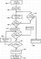
本发明提供了一种用于确定一个增湿气体供应装置中的缺水条件的改良方法。已发现这个方法合适用于在广泛变化的环境条件中确定缺水条件。如图1所示,该方法包括一个两步过程,该过程包括在步骤1010初次确定缺水条件。在观察(在步骤1050)该装置的正常操作的过程中进行这个初次确定。在缺水条件的初次确定之后,该方法在步骤1030对该装置的增湿部分进行暂时的控制,以便在步骤1100进行二次确定,将证实或否认该初次确定。The present invention provides an improved method for determining water deficit conditions in a humidified gas supply. This method has been found suitable for determining water scarcity conditions in widely varying environmental conditions. As shown in FIG. 1 , the method includes a two-step process that includes an initial determination of water scarcity conditions at step 1010 . This initial determination is made during observation (at step 1050) of the normal operation of the device. Following the initial determination of water deficit conditions, the method temporarily controls the humidification portion of the device at step 1030 to make a second determination at step 1100 which will confirm or deny the initial determination.
对于初次确定来说,该装置的控制器可以监控该系统的一系列的特征,如由该系统中包括的一个或多个传感器所感测到的特征。例如,该初次确定可以由背景论述中所描述和论述的许多现有技术方法中的任一个来进行。然而,用于该初次确定的一种优选的方法监控该室出口温度与该加热板温度的一个函数、并且当这个函数离开一个基线值时确定缺水条件的可能性。For an initial determination, the controller of the device may monitor a series of characteristics of the system, such as sensed by one or more sensors included in the system. For example, this initial determination can be made by any of the many prior art methods described and discussed in the background discussion. However, a preferred method for the initial determination monitors a function of the chamber outlet temperature and the heating plate temperature and determines the likelihood of a water starvation condition when this function departs from a baseline value.
根据本发明的一个优选的方面,该二次确定中断对该装置的正常控制并且对该增湿器加热器功率输入进行控制。根据用于该二次确定的方法,该加热器功率被提高至一个最大可用的值持续一个有限的时间段。然后基于监控加热板温度(在步骤1070)来进行该二次确定。这个确定可以是基于指示一个缺水条件的、在这个时间内急剧上升或在这个时间内停留在一个提高的水平、或在这个时间内达到了一个提高的水平的加热板温度。According to a preferred aspect of the invention, the secondary determination interrupts normal control of the device and controls the humidifier heater power input. According to the method used for the secondary determination, the heater power is increased to a maximum available value for a limited period of time. This secondary determination is then made based on monitoring the heating plate temperature (at step 1070). This determination may be based on the heating plate temperature indicating a water shortage condition, rising sharply for this time or staying at an elevated level for this time, or reaching an elevated level for this time.
该控制器然后能够提供该缺水条件的输出(步骤1120)以启动一个使用者警报。该控制器还减少或移除该加热板的功率(步骤1110)。The controller can then provide an output of the water shortage condition (step 1120) to activate a user alarm. The controller also reduces or removes power to the heating plate (step 1110).
已经开发出根据本发明的缺水条件确定方法,这种方法对于在医院环境外面使用增湿气体递送装置具有特殊应用。然而,在旨在用于医院环境的装置的多个控制器中也可以发现该方法的益处。A dehydration condition determination method according to the present invention has been developed which has particular application for use of humidified gas delivery devices outside of a hospital environment. However, benefits of this approach may also be found in controllers of devices intended for use in hospital environments.
该方法能够被用于许多广泛的系统配置中的控制器中。通过实例,三个典型的系统配置展示于图2至图4中并且描述于下文中。这些系统配置是说明性的、而不是这个方法可以被用于其中的系统配置的详尽叙述。The method can be used in controllers in many wide-ranging system configurations. By way of example, three typical system configurations are shown in Figures 2-4 and described below. These system configurations are illustrative and not an exhaustive description of system configurations in which this method can be used.
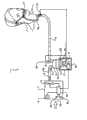
图2a和图2b中示出了根据第一示例性系统配置,使用者2从一个模块式辅助呼吸单元和增湿器系统1接收空气的示意图。该系统1为了治疗目的(例如,为了降低阻塞性睡眠呼吸暂停的发病率,为了提供CPAP治疗,为了提供治疗目的的增湿作用,或类似目的)而向使用者2提供加热的、增湿的气体的加压流。下文对该系统1进行了详细描述。A schematic diagram of a
该辅助呼吸单元或鼓风机单元3具有一个内部压缩机单元、流量发生器或风扇单元13(一般可以被称为流动控制机构)。来自大气的空气经由一个大气进口40进入该鼓风机单元3的外壳、并且被吸入穿过该风扇单元13。该风扇单元13的输出是可调节的,即风扇速度是可变的。加压的气体流离开该风扇单元13和该鼓风机单元3,并且经由一个连接导管4行进至一个增湿器室5,从而通过一个进入端口或进口端口23进入该增湿器室5。The assisted breathing unit or
在使用中该增湿器室5容纳一定体积的水20。在优选的实施方案中,在使用中该增湿器室5被定位在具有一个加热板12的一个增湿器底座单元21的顶部。对该加热板12通电以加热该室5的底座,并且因此加热该室5的内容物。该室5中的水随着被加热而蒸发,并且该增湿器室5内部的气体(在水20的表面上方)变热且变湿。经由进口端口23进入该增湿器室5的气体流通过该加热的水的上方(或穿过这些被加热的、增湿的气体,这种情况适用于较大的室和流速)并且因此变热且变湿。该气体流然后经由一个出口端口或出口端口9离开该增湿器室5,并且进入一个递送导管6。In use the humidifier chamber 5 contains a volume of
当在本说明书中参照本发明提及一个“增湿器单元”时,这应当被当成至少是指该室5,并且如果适当的话,是指该底座单元21以及加热板12。When referring to a "humidifier unit" in this specification with reference to the present invention, this should be taken to refer to at least the chamber 5 and, if appropriate, the base unit 21 and
这些被加热的、增湿的气体沿该递送导管6的长度通过并且经由一个使用者接口7被提供给患者或使用者2。该导管6可以经由一个加热丝(未图示)或类似物来加热以帮助防止雨水冲洗(rain-out)。The heated, humidified gases pass along the length of the delivery catheter 6 and are provided to the patient or
图2a所示的使用者接口7是环绕并且覆盖使用者2的鼻子的一个鼻罩。然而,应指出,鼻套管(如图2b所示)、全罩式面罩、气管造口术接头或任何其他合适的使用者接口可以取代所示的鼻罩。一个中央控制器或控制系统8定位于鼓风机壳体(控制器8a)或增湿器底座单元(控制器8b)之一中。在这种类型的模块式系统中,优选的是使用分离的鼓风机控制器8a和增湿器控制器8b,并且最优选的是控制器8a、8b是相连的(例如通过缆线或类似物),这样它们可以在使用中相互通信。The user interface 7 shown in FIG. 2 a is a nasal mask that surrounds and covers the nose of the
控制系统8经由定位在该增湿器底座单元21或该鼓风机单元3上或二者上的使用者控件11来接收使用者输入信号。在优选的实施方案中,该控制器8还接收来自位于整个系统1的不同点处的传感器的输入。The
图7示出了控制器8的输入和输出中的一些的示意图。应指出,未展示所有可能的连接以及输入和输出,图7代表了这些连接中的一些并且是一个代表性实例。FIG. 7 shows a schematic diagram of some of the inputs and outputs of the
下文将对这些传感器和它们的位置进行更加详细的描述。响应于来自控件11的使用者输入和从这些传感器接收到的信号,该控制系统8确定一个控制输出,在该优选的实施方案中,该控制输出发送多个信号以调节用于该增湿器室加热板12的功率和该风扇13的速度。下文将更详细地描述用于确定该控制器确定该控制输出的方式的程序设计。These sensors and their locations are described in more detail below. In response to user input from
图3示出了使用者2从根据本发明的第二形式的一种集成式鼓风机/增湿器系统100接收空气的示意图。除了增湿器室105已经与该鼓风机单元103集成而形成一个集成单元110以外,该系统以与图2所示且以上描述的模块式系统1非常类似的方式进行操作。由定位在该集成单元110的壳体内部的风扇单元113提供一个加压气体流。由加热板112(在该实施方案中,该加热板是该鼓风机单元103的结构的一体的部分)加热该增湿器室105中的水120。空气经由一个进入端口123进入该增湿器室105、并且经由出口端口109离开该增湿器室105。该气体流经由一个递送导管106和一个接口107被提供给使用者2。该控制器108被容纳于该集成单元100的外壳内。多个使用者控件111被定位在该单元100的外表面上。Figure 3 shows a schematic view of a
图4示出了使用者2从另一形式的呼吸辅助系统200接收空气的示意图。该系统200总体上可以被表征为一个远程源系统、并且经由一个壁进口1000从一个远程源接收空气。FIG. 4 shows a schematic diagram of a
该壁进口1000经由一个进口导管201连接至一个控制单元202上,该控制单元从进口1000接收气体。该控制单元202具有多个传感器250、260、280、290,这些传感器分别测量进入的气体流的湿度、温度和压力以及流量。The
该气体流然后被提供至一个增湿器室205,其中该气体流以一种与以上所述类似的方式被加热且增湿并且被提供给一位使用者。应指出,当针对如系统200的一个远程源系统提及“增湿器单元”时,这应当被当作是指结合了该控制单元202,即来自该远程源的气体可以直接与一个进口相连接,或经由该控制单元202(为了降低压力或类似的)与一个进口相连接,但是该控制单元和该增湿器室应当被解释为属于一个总体的“增湿器单元”。The gas flow is then provided to a
如果有需要,系统200可以通过将该中央源作为O2源、或通过将大气空气与经由定位于该控制单元202中的一个文丘里管90或类似物从该中央源进入的O2进行混合,来向使用者提供O2或一种O2成分。优选的是,该控制单元202还具有一个充当流动控制机构的阀门或类似机构,以便调节穿过该系统200的气体的流速。If desired, the
传感器sensor
图2、图3以及图4示出的模块式和集成式系统1、100和200具有定位在整个系统的多个点处的多个传感器。下文将对涉及该呼吸辅助系统1的这些传感器进行描述。The modular and
如图2所示的优选形式的模块式系统1在以下优选的位置具有至少以下传感器:A preferred form of
1)一个环境温度传感器60,其定位于该鼓风机壳体的内部、附近或之上,被配置或适配成测量从大气进入的空气的温度。最优选的是,该温度传感器60定位于风扇单元13之后(下游)的气流中,并且尽可能靠近该增湿器室的进口或入口。1) An
2)一个增湿器单元出口端口温度传感器63,其定位在该室的出口端口9处、或定位在该递送导管6的装置末端(与患者端相对)处。出口温度传感器63被配置或适配成在气体流离开室5时测量该气体流的温度(在任一配置中,该出口端口温度传感器63可以被认为是在该室出口端口9的近端)。2) A humidifier unit outlet
类似地,多个传感器在图3所示的集成系统100和图4的系统200中被安排在基本上相同的位置处。例如,对于图3的集成系统来说,一个环境温度传感器160定位于鼓风机壳体内的气体流中,恰好在该增湿器室进入端口123之前(上游)。一个室出口端口温度传感器163被定位在该室出口端口109处、并且被配置成在气体流离开室105时测量该气体流的温度(在任一配置中,该出口端口温度传感器163可以被认为是在该室出口端口109的近端)。对于任一实施方案来说,作为替代方案,这个传感器可以定位在该递送导管106的装置末端(与患者端相对)处。一个类似编号的系统被用于图4所示的呼吸辅助系统,即环境温度传感器260、风扇单元213、定位在该室出口端口209处的室出口端口温度传感器263等。Similarly, multiple sensors are arranged at substantially the same location in the
同样优选的是,该呼吸辅助系统1(和100、200)具有定位为邻近该加热板12的一个加热板温度传感器62,该传感器被配置成测量该加热板的温度。具有一个加热板温度传感器的这个或这些呼吸辅助系统是优选的,因为该加热板温度传感器给出了该加热板的状态的即时指示。这个传感器应当在位于热源与该储器之间的热通路之中。因此,例如,优选的是在一个导电板上的一个传感器,该导电板在一侧与水室接触并且在另一侧上具有一个加热器。It is also preferred that the breathing assistance system 1 (and 100, 200) has a heating
而且最优选的是,这些系统具有一个流量探针,即系统1中的流量探针61,该流量探针定位在该风扇单元13的上游并且被配置成测量气体流量。尽管该流量探针可以定位在该风扇的下游或其他任何适当的地方,但是该流量探针的优选位置是该风扇单元的上游。此外,优选的是,一个流量探针形成该系统的一部分,但是流量探针不是绝对必须是该系统的一部分。And most preferably, these systems have a flow probe, flow
现在下文将对该呼吸辅助系统1的布局和操作进行详细描述。系统100与系统200的操作和布局是基本上相同的,并且除了必要的地方之外将不会对其进行详细描述。The layout and operation of the
对于呼吸辅助系统1来说,来自所有传感器的读数被反馈给控制系统8。控制系统8还接收来自这些使用者控件11的输入。For the
另外的替代性传感器布局Additional Alternative Sensor Layouts
在以上概述的装置和方法的变体中,该系统(系统1或系统100或系统200)还具有下文概述的其他传感器。In variants of the devices and methods outlined above, the system (
1)一个患者端温度传感器15(或115或215)被定位在递送导管6的患者端处(或可替代地在接口7之中或之上)。也就是说,在该患者或递送点处或附近。当阅读本说明书时,“患者端”或“使用者端”应当被当作是指靠近该递送导管(例如递送导管6)的使用者端、或在患者接口7之中或之上。除非另外指出特殊的位置,否则这是适用的。在任一配置中,患者端温度传感器15可以被认为是在使用者或患者2之处或附近。1) A patient-end temperature sensor 15 (or 115 or 215) is positioned at the patient-end of the delivery catheter 6 (or alternatively in or on the interface 7). That is, at or near the patient or point of delivery. When reading this specification, "patient end" or "user end" should be taken to mean near the user end of the delivery catheter (eg, delivery catheter 6 ), or in or on patient interface 7 . This applies unless a particular location is indicated otherwise. In either configuration, the patient-
用于初次缺水确定的优选方法Preferred method for initial water deficit determination
参照图6,在本发明的最优选的实施方案中,该控制器在正常使用该装置的过程中的持续进行基础上估算该室出口温度与该加热板功率的一个函数。当这个函数的结果不同于一个基线水平时,该控制器确定缺水状态的可能性。优选的函数是来自传感器63(或163或263)的室出口温度与如加热板负荷周期所表示的加热板功率的一个比率。这个比率可以表示为:Referring to Figure 6, in the most preferred embodiment of the present invention, the controller estimates the chamber outlet temperature as a function of the heating plate power on an ongoing basis during normal use of the device. When the result of this function differs from a baseline level, the controller determines the likelihood of a water shortage condition. The preferred function is a ratio of the chamber outlet temperature from sensor 63 (or 163 or 263) to the heater plate power as indicated by the heater plate duty cycle. This ratio can be expressed as:

其中in
Θ=监控函数,Θ = monitoring function,
CBO_Temp=来自传感器63的室出口温度,CBO_Temp = chamber outlet temperature from
HP_负荷_控制(平均值)=每秒记录的并且对128个数据点进行平均的加热板负荷控制值。HP_LOAD_CONTROL (average) = Heating plate load control value recorded every second and averaged over 128 data points.
在由发明人进行的测试中,已发现这个比率在该增湿室中仍有水时在稳定状态条件下总体上保持恒定,但是在水用完时升高。这是在一系列的环境温度,包括从8°C至32°C的环境温度下的情况。In tests carried out by the inventors, it has been found that this ratio remains generally constant under steady state conditions while there is still water in the humidification chamber, but increases when the water runs out. This is the case over a range of ambient temperatures, including ambient temperatures from 8°C to 32°C.
在最坏的情况下,在该室变干之后,这个比率从先前存在的基线值升高了最少10%。In the worst case, this rate increased by at least 10% from the pre-existing baseline value after the chamber dried out.
可以用许多方法计算基线值θ0。例如,θ0可以是θ的一个移动窗口平均值,或CBO_Temp的移动窗口平均值与该加热板负荷周期的移动窗口平均值的一个函数。作为替代方案,可以用当前值θ来定期地更新值θ0,时间段是例如10分钟或更长。The baseline value θ0 can be calculated in a number of ways. For example, θ0 could be a moving window average of θ, or a function of the moving window average of CBO_Temp and the moving window average of the heater plate duty cycle. Alternatively, the value θ0 may be periodically updated with the current value θ for a period of, for example, 10 minutes or longer.
图5示出这个监控函数的一个实例。图5包括针对在每分钟15升下、以费雪派克MR290增湿室、以及32°C的环境温度操作的费雪派克医疗保健有限公司AIRVO增湿气体递送装置的这个优选函数相对于时间的曲线图。该曲线图是随时间的标准化比率以及随时间的加热板温度。看出该标准化比率保持稳定直至近似t=1,300s,并且然后开始增加,最后达到近似1.8的一个值。Figure 5 shows an example of this monitoring function. Figure 5 includes plots of this preferred function versus time for a Fisher & Paykel Healthcare Limited AIRVO humidified gas delivery device operating at 15 liters per minute, with a Fisher & Paykel Healthcare MR290 humidification chamber, and an ambient temperature of 32°C. Graph. The graph is the normalized ratio over time and the heated plate temperature over time. It is seen that the normalized ratio remains stable until approximately t=1,300s, and then starts increasing, finally reaching a value of approximately 1.8.
对于同费雪派克有限公司AIRVO增湿气体递送装置一起使用的两种不同的增湿器室在三个环境温度和几个流速下进行类似的测试。所测试的条件和流速代表该装置的多个极端操作条件。Similar tests were performed at three ambient temperatures and several flow rates for two different humidifier chambers used with the Fisher & Paykel Ltd. AIRVO humidified gas delivery device. The conditions and flow rates tested were representative of the extreme operating conditions of the device.
表1指示了当该装置进入缺水状态时所估算的比率的标准化最大值。Table 1 indicates the normalized maximum values of the ratios estimated when the device entered a dehydrated state.
表1—标准化最大TCBO/功率之比Table 1—Normalized maximum TCBO /power ratio

在这一系列的条件中观察到对缺水状态的两种典型的系统响应。Two typical system responses to water deficit conditions were observed in this series of conditions.
在第一类型的响应中,该室出口温度降低而该加热板温度升高到一个最大值。在此之后,该室出口温度再一次升高。In a first type of response, the chamber outlet temperature decreases and the heating plate temperature increases to a maximum. After this, the chamber outlet temperature rises again.
在第二类型的响应中,随着该缺水状态的出现,该室出口温度直接升高,而该加热板负荷控制降低了而同时维持一个设定的室出口温度。在这两种典型的响应中,室出口温度与加热板功率的比率与缺水状态开始时的值相比有所升高。在第一类型的响应的情况下,该比率相对该基线值升高与针对该第二类型的响应相比需要更长的时间。In a second type of response, as the water starvation condition occurs, the chamber outlet temperature is directly increased, while the heater plate load control is decreased while maintaining a set chamber outlet temperature. In both typical responses, the ratio of chamber outlet temperature to heating plate power increased compared to the value at the onset of water starvation. In the case of the first type of response, it takes longer for the ratio to rise from the baseline value than for the second type of response.
图6示出这个初次缺水状态检测方法。步骤610代表根据这些系统条件对加热板功率进行持续的控制。这个控制目的在于将所递送的气体温度和湿度保持为或接近优选的水平。Figure 6 shows this initial water shortage state detection method. Step 610 represents continuous control of heater plate power based on these system conditions. The purpose of this control is to maintain the delivered gas temperature and humidity at or near preferred levels.
作为这个控制继续时的一个持续过程,该方法基于步骤620至650的循环来监控可能的缺水状态。As an ongoing process while this control continues, the method is based on a loop of
在步骤620中,该方法读取该室出口温度以及该加热板负荷周期。在步骤630,该方法计算比率θ。在步骤640,该方法计算θ0,为函数θ的最新的值的一个移动窗口平均值。In
在步骤650,该方法将在步骤630计算出的值与在步骤640计算出的值的一个倍数相比较。作为替代方案,该方法将在步骤630计算出的值与在步骤640计算出的一个值加上一个任意偏移量相比较,即图6的步骤650中的方程式可以是θ>θ0+α,其中α对于所有温度或流速来说是恒定的。在示例性实施方案中,这个倍数是1.1,该倍数被证实对于在针对所测试的增湿气体递送装置的一系列使用条件下的缺水状态的初始确定来说是一个可用的阈值。如果当前值显著超过长期值,则该方法继续进行到步骤660并且返回一个可能的缺水状态。如果该当前值小于该长期值或不显著大于该长期值,则该方法返回至步骤620并且在正常使用条件下继续监控气体出口温度和加热板负荷周期。At
该实例描述使用标准化值的一个实现方式,并且步骤650使用一个阈值比率。作为替代方案,这个步骤能够被计算,以便直接使用所测量的值并且基于一个阈值差而确定可能的缺水状态。This example describes one implementation using normalized values, and step 650 uses a threshold ratio. Alternatively, this step can be calculated to use the measured values directly and determine a possible dehydration state based on a threshold difference.
用于二次缺水确定的优选方法Preferred method for secondary water deficit determination
根据本发明,响应初次缺水确定而进行该缺水状态的二次确定。根据优选的实施方案,该方法对该增湿器功率输入进行控制、调节该加热板功率输入并且观察该加热板的温度响应。如果初次监控函数返回一个可能的缺水状态,则这个二次确定被实施来证实该缺水状态。According to the invention, this secondary determination of water shortage status is made in response to the primary water shortage determination. According to a preferred embodiment, the method controls the humidifier power input, adjusts the heating plate power input and observes the temperature response of the heating plate. If the primary monitor function returns a possible water shortage condition, then this secondary determination is implemented to confirm the water shortage condition.
该初次监控函数可能在某些条件下错误地确定一个缺水状态。这些条件包括:电源功率大体上波动、由于流动的阻塞而对该室温度传感器造成的突然的热冲击、或该单元的剧烈振动而引起水从该室进入出口管。室温度的这些被强加的升高很有可能会导致加热板负荷控制的降低并且因此造成这个比率的估算结果发生改变,这将会被该控制器错误地理解为缺水状态。The initial monitoring function may incorrectly determine a water shortage condition under certain conditions. These conditions include: substantial fluctuations in power supply, sudden thermal shock to the chamber temperature sensor due to blockage of flow, or severe vibration of the unit causing water to enter the outlet pipe from the chamber. These imposed increases in chamber temperature will likely result in a decrease in heater plate load control and thus a change in the estimate of this ratio, which will be misinterpreted by the controller as a water shortage condition.
根据本发明,在该控制器确定一个初次缺水状态之后,该控制程序进入用于执行二次缺水确定的例程。According to the present invention, after the controller determines a primary water shortage state, the control program enters a routine for performing secondary water shortage determination.
如图8所示,根据优选的例程,该控制器将该加热板负荷周期增大至最大可用的负荷周期,从而在步骤802中向该加热板施加全功率。该控制程序进行到在步骤806和808监控该加热板温度,直至该加热板温度超过125°C。该控制程序然后进行到在步骤810和814监控该加热板温度继续至超过125°C所持续的时间。如果该加热板温度持续超过125°C达30秒,则该控制器在步骤816中确定一个缺水状态并且给出一个缺水标志。该控制器还在步骤818减少或移除该加热板的功率。As shown in FIG. 8 , according to a preferred routine, the controller increases the heating plate duty cycle to the maximum available duty cycle, thereby applying full power to the heating plate in
如果该控制例程未确定一个缺水状态,那么在步骤820,该控制例程向主操作控制方法返回对该增湿器的控制。这会出现的原因之一是在步骤802中施加最大加热器功率的120秒内,该加热板温度未超过125°C达30秒。实施该例程时,该方法在步骤804启动一个第一计时器并且在步骤808确定温度没有高于125°C之后在步骤822检查这个计时器。如果该计时器仍少于90秒,则该方法进行循环回到步骤806来读取所更新的加热板温度。如果该计时器超过90秒,则该方法从步骤822进行至步骤820,从而返回至正常控制。If the control routine does not determine a water shortage condition, then at
对于使得返回至正常控制的另一个条件来说,该方法包括在步骤812检查该加热板温度是否仍在125°C之上。在每个循环中,该方法在步骤826读取该加热板温度、并且在步骤812针对阈值来检查这个温度。如果当前的加热板温度超过该阈值,则该循环继续,否则该方法进行至步骤822并且检查从步骤802是否已过去90秒。For another condition to return to normal control, the method includes checking at
图5的曲线图中展示了这个检查。该二次确定方法的起点明显是在t=1850秒。该加热板温度已经近似53°C并且缓慢下降。在t=1850秒,该加热板温度急剧上升,迅速达到125°C之上的值并且维持在这些升高的水平上直至该控制器响应所证实的缺水状态而从该加热板移除功率。This check is shown in the graph in Figure 5. The starting point for this quadratic determination method is obviously at t=1850 seconds. The hot plate temperature has been approximately 53°C and is slowly decreasing. At t = 1850 seconds, the heating plate temperature rose sharply, rapidly reaching values above 125°C and maintaining these elevated levels until the controller removed power from the heating plate in response to a confirmed water starvation condition .
基本上来说,这个二次证实过程施加了一个预定的加热器功率、并且监控该加热板温度的响应并且确定这个响应是否是该室处于缺水状态中的特征。Basically, the secondary verification process applies a predetermined heater power and monitors the response of the heater plate temperature and determines whether this response is characteristic of the chamber being in a water starvation condition.
在所描述的优选方法中,所施加的功率是最大可用功率。在一些系统中,如果已经确定一个较低的功率足够实现一种在该装置的所有预期操作条件下能够将一个缺水状态与该室中仍有水时的状态区分开的响应,则所施加的功率可以是一个较小的值。In the preferred method described, the power applied is the maximum available power. In some systems, the applied The power of can be a small value.
根据该优选的方法,该控制器监控该加热板温度升高至一个超过了预定限值的值并且监控该加热板温度在这个限值之上维持一个预定的时间段。According to the preferred method, the controller monitors that the temperature of the heating plate rises to a value above a predetermined limit and monitors that the temperature of the heating plate remains above this limit for a predetermined period of time.
作为替代方案,该控制器能够监控该加热板温度升高的速率,该速率可能已经由实验证明是一个缺水状态的特征,或监控该加热板温度的一些其他特征,与该室中存在水时的状态相比,这些其他特征已经通过实验上被确定是一个缺水状态的特征。Alternatively, the controller can monitor the rate at which the heating plate temperature rises, which may have been experimentally demonstrated to be characteristic of a water starvation condition, or monitor some other characteristic of the heating plate temperature, in relation to the presence of water in the chamber. These other features have been experimentally determined to be characteristic of a dehydrated state when compared to the state at that time.
已经针对一个特定的增湿气体递送装置确定了本发明的这个优选的实施方案中所描述的预定的温度值和时间。对于其他增湿气体递送装置来说,适合的加热板温度阈值和时间段将需要通过实验来确定。The predetermined temperature values and times described in this preferred embodiment of the invention have been determined for a particular humidified gas delivery device. For other humidified gas delivery devices, suitable heating plate temperature thresholds and time periods will need to be determined experimentally.
在对该装置进行了测试和实验的情况下,测试已经显示:在一个缺水状态中,最大被施加的加热器功率实现了超过125°C的加热板温度,持续了恒定且持续的时间。当该增湿的室中仍有水时,具有全负荷周期并且在最高环境条件(32°C)下,该加热板温度不超过123°C。这对于二次确定是最坏的情况,并且在该条件下该二次确定最有可能提供缺水状态的假阳性。因此,对于这个设备来说,已经显示所描述的二次确定可靠地将空的室与仍有水的室区别开。Where the device has been tested and experimented with, tests have shown that the maximum applied heater power achieves a heating plate temperature in excess of 125°C for a constant and sustained time in a water-starved state. With water still in the humidified chamber, with a full load cycle and at the highest ambient conditions (32°C), the heating plate temperature did not exceed 123°C. This is the worst case for the secondary determination, and under this condition the secondary determination is most likely to provide a false positive for water scarcity. Thus, for this device, it has been shown that the described secondary determination reliably distinguishes empty chambers from chambers that still have water.
已经通过特别参照具有加热板的增湿气体递送装置描述了本发明,其中该加热板接触了一个含水储器的导热底座。本发明的系统可以被应用于其他增湿器配置。例如,该增湿器的加热器可以位于储水器内或被集成到该储水器的底座或壁上。在任一种情况下,用于二次确定的温度传感器应当受该储器的内容物和该加热器的热源二者的影响。The invention has been described with particular reference to a humidified gas delivery device having a heating plate contacting the thermally conductive base of a reservoir containing water. The system of the present invention can be applied to other humidifier configurations. For example, the heater of the humidifier may be located within the reservoir or integrated into the base or wall of the reservoir. In either case, the temperature sensor used for the secondary determination should be influenced by both the contents of the reservoir and the heat source of the heater.
在这些情况下,所预期的是,二次确定的阈值温度将会低于针对费雪派克医疗保健有限公司AIRVO装置通过实验所确定出的阈值温度。In these cases, it is expected that the secondarily determined threshold temperature will be lower than that experimentally determined for the Fisher & Paykel Healthcare AIRVO device.
在具有不同的加热器安排的装置中,可能通过一个热敏电阻来确定该加热器温度,该热敏电阻接触了加热元件或接触了与该加热元件相接触的一个导热基板。典型地,当室中有水时,由于将温度限制在由水的沸点限定的这个范围内,使得将会存在该基板对于给定的加热板功率(例如,最大功率)所达到的最大温度。在这些条件下向该加热板供应的热量作为汽化潜热被吸收、并且不会产生温度变化。在水缺乏时,该潜热能量消失,并且超出维持稳态温度所需能量的多余能量导致气体温度升高而不是生成水蒸气。In devices with different heater arrangements, the heater temperature may be determined by a thermistor contacting the heating element or a thermally conductive substrate in contact with the heating element. Typically, when there is water in the chamber, there will be a maximum temperature reached by the substrate for a given heating plate power (eg, maximum power) due to limiting the temperature to this range defined by the boiling point of the water. The heat supplied to the heating plate under these conditions is absorbed as latent heat of vaporization and no temperature change occurs. In the absence of water, this latent heat energy is lost, and excess energy beyond that required to maintain a steady state temperature causes the gas temperature to rise instead of producing water vapor.
本发明的优选实施方案已经被描述为向该加热器提供最大功率达一个持续的时间段。本发明可以被实施为提供一个第一升高的功率给该加热器来使该加热器处于阈值温度之上,而该功率随后减少至一个水平,该水平将该温度维持在该阈值温度之上而不是进一步升高该加热板的温度。这可以例如通过使用基于加热板温度的一个闭合的反馈回路来实现、并且可能特别适用于有待施加给该加热板的可用功率远远大于将温度维持在阈值之上所需要的功率的情况,其中所施加的加热器温度高于在室中只有气体时的阈值水平。Preferred embodiments of the invention have been described as providing maximum power to the heater for a sustained period of time. The present invention may be practiced by providing a first increased power to the heater to keep the heater above a threshold temperature, with the power subsequently reduced to a level that maintains the temperature above the threshold temperature Rather than raising the temperature of the heating plate further. This can be achieved, for example, by using a closed feedback loop based on the temperature of the heating plate, and may be particularly applicable where the available power to be applied to the heating plate is much greater than that required to maintain the temperature above a threshold, where The applied heater temperature is above the threshold level when there is only gas in the chamber.
Claims (15)
Priority Applications (1)
| Application Number | Priority Date | Filing Date | Title |
|---|---|---|---|
| CN201610344281.1ACN106039518B (en) | 2010-04-27 | 2011-04-26 | Water shortage alarm |
Applications Claiming Priority (3)
| Application Number | Priority Date | Filing Date | Title |
|---|---|---|---|
| US32854810P | 2010-04-27 | 2010-04-27 | |
| US61/328,548 | 2010-04-27 | ||
| PCT/NZ2011/000058WO2011136664A1 (en) | 2010-04-27 | 2011-04-26 | Water out alarm |
Related Child Applications (1)
| Application Number | Title | Priority Date | Filing Date |
|---|---|---|---|
| CN201610344281.1ADivisionCN106039518B (en) | 2010-04-27 | 2011-04-26 | Water shortage alarm |
Publications (2)
| Publication Number | Publication Date |
|---|---|
| CN103037926Atrue CN103037926A (en) | 2013-04-10 |
| CN103037926B CN103037926B (en) | 2016-06-29 |
Family
ID=44861741
Family Applications (2)
| Application Number | Title | Priority Date | Filing Date |
|---|---|---|---|
| CN201610344281.1AActiveCN106039518B (en) | 2010-04-27 | 2011-04-26 | Water shortage alarm |
| CN201180031631.4AActiveCN103037926B (en) | 2010-04-27 | 2011-04-26 | water shortage alarm |
Family Applications Before (1)
| Application Number | Title | Priority Date | Filing Date |
|---|---|---|---|
| CN201610344281.1AActiveCN106039518B (en) | 2010-04-27 | 2011-04-26 | Water shortage alarm |
Country Status (8)
| Country | Link |
|---|---|
| US (5) | US9393379B2 (en) |
| JP (1) | JP5995289B2 (en) |
| CN (2) | CN106039518B (en) |
| AU (1) | AU2011245770B2 (en) |
| CA (3) | CA2968099C (en) |
| DE (1) | DE112011101484T5 (en) |
| GB (2) | GB2535087B (en) |
| WO (1) | WO2011136664A1 (en) |
Cited By (6)
| Publication number | Priority date | Publication date | Assignee | Title |
|---|---|---|---|---|
| CN109789288A (en)* | 2016-07-19 | 2019-05-21 | 费雪派克医疗保健有限公司 | Water shortage alarm determination |
| CN109999307A (en)* | 2019-03-11 | 2019-07-12 | 北京怡和嘉业医疗科技股份有限公司 | A kind of detection method and device of humidifier dry-fire condition |
| CN110772694A (en)* | 2019-12-06 | 2020-02-11 | 常州市第一人民医院 | A breathing apparatus with humidification function |
| CN112146232A (en)* | 2020-09-15 | 2020-12-29 | 珠海格力电器股份有限公司 | Humidifier and water shortage control method thereof |
| CN112807540A (en)* | 2021-02-05 | 2021-05-18 | 广东普门生物医疗科技有限公司 | Breathing humidifier, dry burning detection method thereof and computer readable storage medium |
| CN113418728A (en)* | 2021-05-31 | 2021-09-21 | 深圳市科曼医疗设备有限公司 | Method, device and equipment for detecting dry-burning state of humidifying equipment and storage medium |
Families Citing this family (19)
| Publication number | Priority date | Publication date | Assignee | Title |
|---|---|---|---|---|
| DE112011101484T5 (en) | 2010-04-27 | 2013-07-11 | Fisher & Paykel Healthcare Ltd. | Water depletion alarm |
| IN2014CN04521A (en)* | 2011-12-02 | 2015-09-11 | Koninkl Philips Nv | |
| EP2938378A1 (en)* | 2012-12-28 | 2015-11-04 | Koninklijke Philips N.V. | Humidity control liquid maximization pressure support device |
| EP3039593B1 (en)* | 2013-08-29 | 2021-06-16 | Löwenstein Medical Technology S.A. | Operating- and information system for a breathing apparatus |
| NZ717147A (en)* | 2013-10-21 | 2017-08-25 | Resmed Ltd | Methods of detecting a quantity of water in a humidifier |
| CN111110977B (en)* | 2014-04-16 | 2023-05-09 | 费雪派克医疗保健有限公司 | Method and system for delivering gas to a patient |
| CA3175751A1 (en)* | 2014-09-03 | 2016-03-10 | Fisher & Paykel Healthcare Limited | Deterministically controlled humidification system |
| JP6029044B1 (en)* | 2016-03-01 | 2016-11-24 | 株式会社グレイトチレン | Wet high concentration hydrogen mixed gas breathing system |
| CN110520181A (en)* | 2017-01-19 | 2019-11-29 | 科奥实验室私人有限公司 | Continuing positive airway pressure unit |
| US20190201651A1 (en)* | 2017-12-29 | 2019-07-04 | Koninklijke Philips N.V. | Humidifier start-up method and system employing same |
| IT201800003552A1 (en)* | 2018-03-14 | 2019-09-14 | St Microelectronics Srl | PIEZOELECTRIC VALVE MODULE, METHOD OF MANUFACTURE OF THE VALVE MODULE, METHOD OF OPERATION OF THE VALVE MODULE AND BREATHING AID DEVICE INCLUDING ONE OR MORE VALVE MODULES |
| CN108568019A (en)* | 2018-05-03 | 2018-09-25 | 邢士刚 | A kind of Multifunctional internal medicine clinic breathing equipment |
| AU2019319426B2 (en) | 2018-08-10 | 2025-03-27 | Fisher & Paykel Healthcare Limited | Heater plate assembly in humidifier systems for medical use |
| CN111142599B (en)* | 2019-12-31 | 2021-11-02 | 湖南明康中锦医疗科技发展有限公司 | Humidification amount control system and method for respiratory support equipment and respiratory support equipment |
| CN111956085B (en)* | 2020-07-13 | 2024-06-14 | 华帝股份有限公司 | Water shortage detection method of cooking equipment |
| CN112220998B (en)* | 2020-10-26 | 2021-04-30 | 联赢医疗科技有限公司 | Breathing machine system |
| CN112220999B (en)* | 2020-10-26 | 2021-05-18 | 联赢医疗科技有限公司 | Self-adaptive respirator system |
| CN115444279B (en)* | 2021-06-08 | 2025-09-09 | 九阳股份有限公司 | Water dispenser heating device protection method and water dispenser |
| CN115554554B (en)* | 2022-06-20 | 2024-09-06 | 广州医软智能科技有限公司 | Water shortage judging method and system for heating system, electronic equipment and storage medium |
Citations (7)
| Publication number | Priority date | Publication date | Assignee | Title |
|---|---|---|---|---|
| US4676237A (en)* | 1985-01-29 | 1987-06-30 | Boutade Worldwide Investments Nv | Inhaler device |
| JP2000104960A (en)* | 1998-09-30 | 2000-04-11 | Sanyo Electric Co Ltd | Humidifier |
| JP2000274753A (en)* | 1999-03-23 | 2000-10-06 | Aiwa Co Ltd | Humidifier |
| CN1314192A (en)* | 2000-03-21 | 2001-09-26 | 菲什尔·派克尔公司 | breathing assistance equipment |
| CN1667400A (en)* | 2000-10-20 | 2005-09-14 | 菲舍尔和佩克尔保健有限公司 | Humidity Sensor |
| CN101112637A (en)* | 1997-06-17 | 2008-01-30 | 菲舍尔和佩克尔有限公司 | respiratory system humidifier |
| CN101203073A (en)* | 2006-12-14 | 2008-06-18 | 全能电业科技(深圳)有限公司 | Method for detecting boiler dry burning |
Family Cites Families (23)
| Publication number | Priority date | Publication date | Assignee | Title |
|---|---|---|---|---|
| US3982098A (en)* | 1974-12-23 | 1976-09-21 | Trostler Richard M | Heater and control system |
| GB2185161B (en)* | 1985-12-09 | 1990-03-21 | Otter Controls Ltd | Controls for electrically powered heating elements |
| US5988164A (en)* | 1995-07-31 | 1999-11-23 | Paluch; Bernard | Breathing circuits with humidity controls |
| US5679274A (en) | 1996-05-13 | 1997-10-21 | The West Bend Company | Circuit and method for controlling electrical heater in a distiller |
| US6649881B2 (en)* | 1998-06-04 | 2003-11-18 | American Water Heater Company | Electric water heater with pulsed electronic control and detection |
| JP2001029474A (en)* | 1999-07-21 | 2001-02-06 | Central Uni Co Ltd | Heated humidifier inhaler |
| CA2370995C (en)* | 2001-09-13 | 2010-08-17 | Fisher & Paykel Healthcare Limited | Breathing assistance apparatus |
| EP1542756B1 (en)* | 2002-08-30 | 2016-10-19 | Fisher & Paykel Healthcare Limited | Humidification system |
| EP1651158B1 (en) | 2003-07-28 | 2018-11-07 | Salter Labs | Respiratory therapy system including a nasal cannula assembly |
| US7099572B2 (en)* | 2004-06-30 | 2006-08-29 | Synapse, Inc. | Water heating system and method for detecting a dry fire condition for a heating element |
| CN101252966B (en)* | 2005-05-26 | 2012-07-18 | 菲舍尔和佩克尔保健有限公司 | Breathing assistance apparatus |
| US7473868B2 (en)* | 2005-06-30 | 2009-01-06 | R. W. Beckett Corporation | Fail safe HVAC temperature and medium presence sensor |
| US8739780B2 (en) | 2005-08-15 | 2014-06-03 | Resmed Limited | Low cost CPAP flow generator and humidifier assembly |
| US8197123B2 (en)* | 2007-10-29 | 2012-06-12 | Smiths Medical Asd, Inc. | Thermistor circuit calibration |
| US8511305B2 (en)* | 2007-10-29 | 2013-08-20 | Smiths Medical Asd, Inc. | Redundant power control for respiratory system heaters |
| DE202007015930U1 (en)* | 2007-11-13 | 2008-03-06 | Lmt Lammers Medical Technology Gmbh | humidifier |
| US8269638B2 (en) | 2008-01-23 | 2012-09-18 | Lexion Medical Llc | Hydration alert |
| CA2713012A1 (en)* | 2008-01-25 | 2009-07-30 | Salter Labs | Respiratory therapy system including a nasal cannula assembly |
| JP4409612B1 (en)* | 2008-09-19 | 2010-02-03 | シャープ株式会社 | Cooker |
| DE112010005006T5 (en) | 2009-12-23 | 2012-11-15 | Fisher & Paykel Healthcare Ltd. | Humidified gas supply device and method for its control |
| US12226569B2 (en)* | 2009-12-23 | 2025-02-18 | Fisher & Paykel Healthcare Limted | Systems for laparoscopic surgery |
| DE112011101484T5 (en) | 2010-04-27 | 2013-07-11 | Fisher & Paykel Healthcare Ltd. | Water depletion alarm |
| US8511651B2 (en)* | 2011-03-29 | 2013-08-20 | Smiths Medical Asd, Inc. | Heater unit humidification chamber monitor |
- 2011
- 2011-04-26DEDE112011101484Tpatent/DE112011101484T5/enactivePending
- 2011-04-26CACA2968099Apatent/CA2968099C/enactiveActive
- 2011-04-26AUAU2011245770Apatent/AU2011245770B2/enactiveActive
- 2011-04-26USUS13/643,901patent/US9393379B2/enactiveActive
- 2011-04-26WOPCT/NZ2011/000058patent/WO2011136664A1/enactiveApplication Filing
- 2011-04-26CNCN201610344281.1Apatent/CN106039518B/enactiveActive
- 2011-04-26GBGB1608525.0Apatent/GB2535087B/enactiveActive
- 2011-04-26JPJP2013507902Apatent/JP5995289B2/enactiveActive
- 2011-04-26CNCN201180031631.4Apatent/CN103037926B/enactiveActive
- 2011-04-26GBGB1219284.5Apatent/GB2492038B/enactiveActive
- 2011-04-26CACA3139595Apatent/CA3139595A1/enactivePending
- 2011-04-26CACA2797509Apatent/CA2797509C/enactiveActive
- 2016
- 2016-06-06USUS15/174,485patent/US10532178B2/enactiveActive
- 2019
- 2019-12-05USUS16/704,360patent/US11679227B2/enactiveActive
- 2023
- 2023-04-27USUS18/308,565patent/US11957844B2/enactiveActive
- 2024
- 2024-03-19USUS18/610,174patent/US20240307649A1/enactivePending
Patent Citations (7)
| Publication number | Priority date | Publication date | Assignee | Title |
|---|---|---|---|---|
| US4676237A (en)* | 1985-01-29 | 1987-06-30 | Boutade Worldwide Investments Nv | Inhaler device |
| CN101112637A (en)* | 1997-06-17 | 2008-01-30 | 菲舍尔和佩克尔有限公司 | respiratory system humidifier |
| JP2000104960A (en)* | 1998-09-30 | 2000-04-11 | Sanyo Electric Co Ltd | Humidifier |
| JP2000274753A (en)* | 1999-03-23 | 2000-10-06 | Aiwa Co Ltd | Humidifier |
| CN1314192A (en)* | 2000-03-21 | 2001-09-26 | 菲什尔·派克尔公司 | breathing assistance equipment |
| CN1667400A (en)* | 2000-10-20 | 2005-09-14 | 菲舍尔和佩克尔保健有限公司 | Humidity Sensor |
| CN101203073A (en)* | 2006-12-14 | 2008-06-18 | 全能电业科技(深圳)有限公司 | Method for detecting boiler dry burning |
Cited By (9)
| Publication number | Priority date | Publication date | Assignee | Title |
|---|---|---|---|---|
| CN109789288A (en)* | 2016-07-19 | 2019-05-21 | 费雪派克医疗保健有限公司 | Water shortage alarm determination |
| CN109789288B (en)* | 2016-07-19 | 2022-08-05 | 费雪派克医疗保健有限公司 | Water shortage alarm determination |
| CN109999307A (en)* | 2019-03-11 | 2019-07-12 | 北京怡和嘉业医疗科技股份有限公司 | A kind of detection method and device of humidifier dry-fire condition |
| CN109999307B (en)* | 2019-03-11 | 2022-04-08 | 北京怡和嘉业医疗科技股份有限公司 | Method and device for detecting dry-burning state of humidifier |
| CN110772694A (en)* | 2019-12-06 | 2020-02-11 | 常州市第一人民医院 | A breathing apparatus with humidification function |
| CN110772694B (en)* | 2019-12-06 | 2020-06-05 | 常州市第一人民医院 | Breathing device with humidifying function |
| CN112146232A (en)* | 2020-09-15 | 2020-12-29 | 珠海格力电器股份有限公司 | Humidifier and water shortage control method thereof |
| CN112807540A (en)* | 2021-02-05 | 2021-05-18 | 广东普门生物医疗科技有限公司 | Breathing humidifier, dry burning detection method thereof and computer readable storage medium |
| CN113418728A (en)* | 2021-05-31 | 2021-09-21 | 深圳市科曼医疗设备有限公司 | Method, device and equipment for detecting dry-burning state of humidifying equipment and storage medium |
Also Published As
| Publication number | Publication date |
|---|---|
| CA2968099A1 (en) | 2011-11-03 |
| CA3139595A1 (en) | 2011-11-03 |
| US20200129725A1 (en) | 2020-04-30 |
| CA2797509C (en) | 2018-06-19 |
| DE112011101484T5 (en) | 2013-07-11 |
| CN103037926B (en) | 2016-06-29 |
| GB201219284D0 (en) | 2012-12-12 |
| GB201608525D0 (en) | 2016-06-29 |
| US10532178B2 (en) | 2020-01-14 |
| CA2797509A1 (en) | 2011-11-03 |
| GB2535087B (en) | 2016-10-05 |
| JP2013524991A (en) | 2013-06-20 |
| US11679227B2 (en) | 2023-06-20 |
| WO2011136664A9 (en) | 2013-01-03 |
| GB2492038B (en) | 2016-08-10 |
| GB2535087A (en) | 2016-08-10 |
| US20130104886A1 (en) | 2013-05-02 |
| WO2011136664A1 (en) | 2011-11-03 |
| JP5995289B2 (en) | 2016-09-21 |
| US9393379B2 (en) | 2016-07-19 |
| US11957844B2 (en) | 2024-04-16 |
| AU2011245770B2 (en) | 2015-01-22 |
| CN106039518B (en) | 2020-01-10 |
| US20240307649A1 (en) | 2024-09-19 |
| CN106039518A (en) | 2016-10-26 |
| GB2492038A (en) | 2012-12-19 |
| US20160354574A1 (en) | 2016-12-08 |
| US20230330381A1 (en) | 2023-10-19 |
| AU2011245770A1 (en) | 2012-11-22 |
| CA2968099C (en) | 2022-01-04 |
Similar Documents
| Publication | Publication Date | Title |
|---|---|---|
| CN103037926B (en) | water shortage alarm | |
| JP2013524991A6 (en) | Water out alarm | |
| JP2025105625A (en) | A device that supplies gas to a patient | |
| JP6433659B2 (en) | System and method for managing humidified gas for ventilated patients | |
| US7106955B2 (en) | Humidity controller | |
| CA2391787C (en) | Humidity controller | |
| CN102740918B (en) | Humidified gas delivery device and control method thereof | |
| AU2024200492A1 (en) | Water out alarm | |
| AU7946101A (en) | Humidity controller |
Legal Events
| Date | Code | Title | Description |
|---|---|---|---|
| C06 | Publication | ||
| PB01 | Publication | ||
| C10 | Entry into substantive examination | ||
| SE01 | Entry into force of request for substantive examination | ||
| C14 | Grant of patent or utility model | ||
| GR01 | Patent grant |