CN103036028A - Horn antenna - Google Patents
Horn antennaDownload PDFInfo
- Publication number
- CN103036028A CN103036028ACN2011102979037ACN201110297903ACN103036028ACN 103036028 ACN103036028 ACN 103036028ACN 2011102979037 ACN2011102979037 ACN 2011102979037ACN 201110297903 ACN201110297903 ACN 201110297903ACN 103036028 ACN103036028 ACN 103036028A
- Authority
- CN
- China
- Prior art keywords
- metal
- metamaterial
- refractive index
- horn antenna
- artificial
- Prior art date
- Legal status (The legal status is an assumption and is not a legal conclusion. Google has not performed a legal analysis and makes no representation as to the accuracy of the status listed.)
- Granted
Links
Images


Landscapes
- Aerials With Secondary Devices (AREA)
Abstract
Translated fromChinese
Description
Translated fromChinese技术领域technical field
本发明涉及天线技术领域,尤其涉及一种喇叭天线。The invention relates to the technical field of antennas, in particular to a horn antenna.
背景技术Background technique
喇叭天线是指波导终端张开成喇叭状的天线,其得名源于其形状。喇叭天线结构简单且方向图易于控制,可用作方向性天线也可用作馈源。Horn antenna refers to the antenna whose waveguide terminal is opened into a horn shape, and its name comes from its shape. The horn antenna has a simple structure and is easy to control the pattern, which can be used as a directional antenna or as a feed source.
喇叭天线的辐射角度由喇叭口的尺寸决定,当需要扩大其辐射角度时,相应的需要扩大其喇叭口的尺寸。在目前各类电子元器件追求小型化、高增益化的趋势下,如何在不扩大喇叭天线的喇叭口尺寸又扩大其辐射范围成为亟待解决的问题。The radiation angle of the horn antenna is determined by the size of the horn mouth. When the radiation angle needs to be enlarged, the size of the horn mouth needs to be enlarged accordingly. Under the current trend of pursuing miniaturization and high gain of various electronic components, how to expand the radiation range of the horn antenna without expanding the size of the horn antenna has become an urgent problem to be solved.
发明内容Contents of the invention
本发明所要解决的技术问题在于,针对现有技术的上述不足,提出一种辐射范围较宽且辐射角度可自由控制、尺寸较小的喇叭天线。The technical problem to be solved by the present invention is to propose a horn antenna with a wide radiation range, freely controllable radiation angle and small size in view of the above-mentioned deficiencies in the prior art.
本发明解决其技术问题,采用的技术方案是提出一种喇叭天线,其包括:天线本体、位于天线本体口径面正前方的超材料以及紧贴于所述超材料背部的反射板,所述天线本体的中心轴线穿过所述超材料的中心点;所述超材料包括基材以及周期排布于所述基材上的多个人造金属微结构,所述超材料上的折射率呈圆形分布,圆心处的折射率最小,随着半径的增大,折射率逐渐增大,相同半径处的折射率相同。The present invention solves its technical problems, and the technical solution adopted is to propose a horn antenna, which includes: an antenna body, a metamaterial positioned directly in front of the aperture surface of the antenna body, and a reflector close to the back of the metamaterial, the antenna The central axis of the body passes through the central point of the metamaterial; the metamaterial includes a substrate and a plurality of artificial metal microstructures periodically arranged on the substrate, and the refractive index on the metamaterial is circular Distribution, the refractive index at the center of the circle is the smallest, as the radius increases, the refractive index gradually increases, and the refractive index at the same radius is the same.
进一步地,所述超材料上以其中心点为圆心,半径为r处的折射率为:Further, the metamaterial has its center point as the center, and the refractive index at the radius r is:
其中,d为所述超材料的厚度;ss为由所述天线本体等效的点源距所述超材料中心点的距离;n(0)为所述超材料中心点的折射率值;θ为电磁波出射角。Wherein, d is the thickness of the metamaterial; ss is the distance from the point source equivalent to the metamaterial center point by the antenna body; n (0) is the refractive index value of the metamaterial center point; θ is the emission angle of the electromagnetic wave.
进一步地,所述天线本体的口径面形状为圆形、矩形或者梯形。Further, the shape of the aperture surface of the antenna body is circular, rectangular or trapezoidal.
进一步地,所述多个人造金属微结构具有相同的几何形状,所述多个人造金属微结构在所述基材上呈圆形分布,圆心处的人造金属微结构尺寸最小,随着半径的增大,人造金属微结构的尺寸增大,相同半径处的人造金属微结构尺寸相同。Further, the plurality of artificial metal microstructures have the same geometric shape, and the plurality of artificial metal microstructures are distributed circularly on the substrate, and the size of the artificial metal microstructure at the center of the circle is the smallest. The size of the artificial metal microstructure increases, and the size of the artificial metal microstructure at the same radius is the same.
进一步地,所述人造金属微结构的几何形状为“工”字形,包括竖直的第一金属分支以及位于所述第一金属分支两端且垂直于所述第一金属分支的第二金属分支。Further, the geometric shape of the artificial metal microstructure is "I" shape, including a vertical first metal branch and a second metal branch located at both ends of the first metal branch and perpendicular to the first metal branch .
进一步地,所述几何形状还包括位于所述第二金属分支两端且垂直于所述第二金属分支的第三金属分支。Further, the geometric shape further includes a third metal branch located at both ends of the second metal branch and perpendicular to the second metal branch.
进一步地,所述人造金属微结构的几何形状为平面雪花型,包括相互垂直的两条第一金属分支以及位于所述第一金属分支两端且垂直于所述第一金属分支的第二金属分支。Further, the geometric shape of the artificial metal microstructure is a plane snowflake, including two first metal branches perpendicular to each other and a second metal branch located at both ends of the first metal branch and perpendicular to the first metal branch. branch.
进一步地,所述基材为高分子材料、陶瓷材料、铁电材料、铁氧材料或者铁磁材料。Further, the substrate is a polymer material, a ceramic material, a ferroelectric material, a ferrite material or a ferromagnetic material.
进一步地,所述反射板为金属反射板。Further, the reflector is a metal reflector.
进一步地,所述人造金属微结构通过蚀刻、电镀、钻刻、光刻、电子刻或离子刻周期排布于所述基材上。Further, the artificial metal microstructure is periodically arranged on the substrate by etching, electroplating, drilling, photolithography, electron etching or ion etching.
本发明通过在现有的天线本体上增设具有发散功能的超材料以及位于超材料背后的反射板,天线本体辐射的电磁波经过超材料被发散后再被反射板反射,由天线本体传播出去的电磁波辐射角度更大。且本发明在超材料背部增设反射板,使得超材料能两次响应电磁波,减少了超材料的厚度。In the present invention, by adding a metamaterial with divergence function and a reflector behind the metamaterial to the existing antenna body, the electromagnetic wave radiated by the antenna body is diverged by the metamaterial and then reflected by the reflector, and the electromagnetic wave transmitted by the antenna body The radiation angle is larger. Moreover, the present invention adds a reflection plate on the back of the metamaterial, so that the metamaterial can respond to electromagnetic waves twice, reducing the thickness of the metamaterial.
附图说明Description of drawings
图1为构成超材料的基本单元的立体结构示意图;Figure 1 is a schematic diagram of the three-dimensional structure of the basic unit constituting the metamaterial;
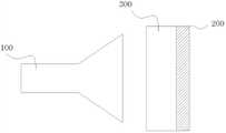
图2为本发明一种喇叭天线的结构示意图;Fig. 2 is the structural representation of a kind of horn antenna of the present invention;
图3为本发明一种喇叭天线中超材料的立体结构示意图;3 is a schematic diagram of a three-dimensional structure of a metamaterial in a horn antenna of the present invention;
图4为本发明喇叭天线上的超材料纵剖面上折射率分布计算示意图;Fig. 4 is a schematic diagram of calculating the refractive index distribution on the longitudinal section of the metamaterial on the horn antenna of the present invention;
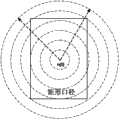
图5为当喇叭天线的天线本体口径面形状为矩形时,超材料的截面示意图;Fig. 5 is a cross-sectional schematic diagram of a metamaterial when the shape of the antenna body aperture surface of the horn antenna is rectangular;
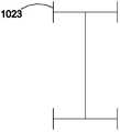
图6为能对电磁波产生响应以改变超材料基本单元折射率的第一较佳实施方式的人造金属微结构的几何形状拓扑图案;Fig. 6 is the geometric topological pattern of the artificial metal microstructure of the first preferred embodiment that can respond to electromagnetic waves to change the refractive index of the basic unit of the metamaterial;
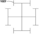
图6a为图6中人造金属微结构几何形状拓扑图案的衍生图案;Figure 6a is a derivative pattern of the geometric topological pattern of the artificial metal microstructure in Figure 6;
图7为能对电磁波产生响应以改变超材料基本单元折射率的第二较佳实施方式的人造金属微结构的几何形状拓扑图案;Fig. 7 is the geometric topological pattern of the artificial metal microstructure that can respond to electromagnetic waves to change the refractive index of the basic unit of the metamaterial in the second preferred embodiment;
图7a为图7中人造金属微结构几何形状拓扑图案的衍生图案。Fig. 7a is a derivative pattern of the geometric topological pattern of the artificial metal microstructure in Fig. 7.
具体实施方式Detailed ways
光,作为电磁波的一种,其在穿过玻璃的时候,因为光线的波长远大于原子的尺寸,因此我们可以用玻璃的整体参数,例如折射率,而不是组成玻璃的原子的细节参数来描述玻璃对光线的响应。相应的,在研究材料对其他电磁波响应的时候,材料中任何尺度远小于电磁波波长的结构对电磁波的响应也可以用材料的整体参数,例如介电常数ε和磁导率μ来描述。通过设计材料每点的结构使得材料各点的介电常数和磁导率都相同或者不同从而使得材料整体的介电常数和磁导率呈一定规律排布,规律排布的磁导率和介电常数即可使得材料对电磁波具有宏观上的响应,例如汇聚电磁波、发散电磁波等。该类具有规律排布的磁导率和介电常数的材料我们称之为超材料。Light, as a kind of electromagnetic wave, when it passes through glass, because the wavelength of light is much larger than the size of atoms, we can use the overall parameters of the glass, such as the refractive index, rather than the detailed parameters of the atoms that make up the glass to describe The response of glass to light. Correspondingly, when studying the response of materials to other electromagnetic waves, the response of any structure in the material whose scale is much smaller than the wavelength of the electromagnetic wave to electromagnetic waves can also be described by the overall parameters of the material, such as the dielectric constant ε and magnetic permeability μ. By designing the structure of each point of the material, the dielectric constant and magnetic permeability of each point of the material are the same or different, so that the overall dielectric constant and magnetic permeability of the material are arranged in a certain order, and the regularly arranged magnetic permeability and magnetic permeability The electrical constant can make the material have a macroscopic response to electromagnetic waves, such as converging electromagnetic waves and diverging electromagnetic waves. Such materials with regularly arranged magnetic permeability and permittivity are called metamaterials.
如图1所示,图1为构成超材料的基本单元的立体结构示意图。超材料的基本单元包括人造微结构1以及该人造微结构附着的基材2。本发明中,人造微结构为人造金属微结构,人造金属微结构具有能对入射电磁波电场和/或磁场产生响应的平面或立体拓扑结构,改变每个超材料基本单元上的人造金属微结构的图案和/或尺寸即可改变每个超材料基本单元对入射电磁波的响应。多个超材料基本单元按一定规律排列即可使得超材料对电磁波具有宏观的响应。由于超材料整体需对入射电磁波有宏观电磁响应因此各个超材料基本单元对入射电磁波的响应需形成连续响应,这要求每一超材料基本单元的尺寸为入射电磁波的十分之一至五分之一,优选为入射电磁波的十分之一。本段描述中,我们人为的将超材料整体划分为多个超材料基本单元,但应知此种划分方法仅为描述方便,不应看成超材料由多个超材料基本单元拼接或组装而成,实际应用中超材料是将人造金属微结构周期排布于基材上即可构成,工艺简单且成本低廉。周期排布即指上述我们人为划分的各个超材料基本单元上的人造金属微结构能对入射电磁波产生连续的电磁响应。As shown in FIG. 1 , FIG. 1 is a schematic diagram of a three-dimensional structure of a basic unit constituting a metamaterial. The basic unit of a metamaterial includes an
请参照图2,图2为本发明喇叭天线的结构示意图。图2中,喇叭天线包括天线本体100、位于天线本体口径面正前方的超材料300以及位于超材料300背后的反射板200。天线本体的对称轴线穿过超材料的中心点。本实施例中,反射板200采用金属反射板。在超材料背部增设反射板使得超材料能两次响应天线本体发出的电磁波从而减小超材料的厚度。Please refer to FIG. 2 , which is a schematic structural diagram of the horn antenna of the present invention. In FIG. 2 , the horn antenna includes an antenna body 100 , a
请参照图3,图3为本发明喇叭天线中超材料的立体结构示意图。图3中,超材料300包括基材301,以及周期排布于基材上的多个人造金属微结构302。本实施例中,为封装方便以及保护人造金属微结构,在多个人造金属微结构302上还覆盖有一层厚度和材质均与基材301相同的覆盖层303。多个人造金属微结构302均有相同的几何形状,多个人造金属微结构302在基材301上呈圆形分布,圆心处,也即超材料中心处的人造金属微结构尺寸最小,随着半径的增大,人造金属微结构尺寸增大,相同半径处的人造金属微结构尺寸相同。Please refer to FIG. 3 . FIG. 3 is a three-dimensional structural diagram of the metamaterial in the horn antenna of the present invention. In FIG. 3 , a
当把超材料300从中间剖开时,超材料300的纵剖面上的折射率分布旋转一圈即为超材料300的整体折射率分布。我们可以通过超材料300纵剖面上的折射率分布来得知超材料300整体的折射率分布。如图4所示,图4为本发明喇叭天线上的超材料纵剖面上折射率分布计算示意图。图4中,天线本体被等效为一个点源。点源发出的球面波在经过超材料后被发散,发散后的电磁波被金属反射板200反射,反射后的电磁波再次进入超材料300内部被发散并最终出射出去,电磁波出射角为θ。经计算,我们可以得出超材料上以其中心点为圆心、半径为r处的折射率值为:When the
其中,r即为具有相同折射率的人造金属微结构距超材料中心点的半径值,也即图4中,超材料纵剖面上距中心轴线的距离;d为超材料的厚度;ss为天线本体的等效点源距超材料中心点的距离;n(0)为超材料中心点的折射率值,也即超材料的最小折射率值;θ为电磁波的出射角。Among them, r is the radius value of the artificial metal microstructure with the same refractive index from the center point of the metamaterial, that is, the distance from the central axis on the longitudinal section of the metamaterial in Figure 4; d is the thickness of the metamaterial; ss is the antenna The distance between the equivalent point source of the body and the center point of the metamaterial; n(0) is the refractive index value of the center point of the metamaterial, that is, the minimum refractive index value of the metamaterial; θ is the exit angle of the electromagnetic wave.
进一步地,由于n(0)为超材料的最小折射率,当n(0)与自由空间折射率相差较大时,自由空间入射到超材料上的电磁波会部分被反射。在此种情况下,还可在超材料两侧增设阻抗匹配层,以减少反射,增大增益。Furthermore, since n(0) is the minimum refractive index of the metamaterial, when the difference between n(0) and the free space refractive index is large, the electromagnetic waves incident on the metamaterial in free space will be partially reflected. In this case, an impedance matching layer can also be added on both sides of the metamaterial to reduce reflection and increase gain.
同时,当本发明喇叭天线喇叭本体的口径形状发生变化时,仅需要在原有的圆形设计的基础上截取所需的形状即可。如图5所示,图5中,虚线部分即为初始设计时折射率和人造金属微结构的圆环分布图,当天线本体口径面形状为矩形时,直接在圆环分布的基础上截取实线部分的矩形即可。At the same time, when the aperture shape of the horn body of the horn antenna of the present invention changes, it is only necessary to cut out the required shape on the basis of the original circular design. As shown in Figure 5, in Figure 5, the dotted line part is the circular distribution diagram of the refractive index and the artificial metal microstructure in the initial design. The rectangle of the line part is enough.
满足上述超材料折射率分布要求的人造金属微结构的几何形状有多种,但都为能对入射电磁波产生响应的几何形状。最典型的即为“工”字形人造金属微结构。下面详细描述几种人造金属微结构几何形状。超材料上各点折射率对应的人造金属微结构的尺寸可通过计算机仿真得出,也可通过人工计算得出。There are many geometric shapes of the artificial metal microstructures that meet the requirements of the above-mentioned refractive index distribution of metamaterials, but all of them are geometric shapes that can respond to incident electromagnetic waves. The most typical one is the "I" shaped artificial metal microstructure. Several artificial metal microstructure geometries are described in detail below. The size of the artificial metal microstructure corresponding to the refractive index of each point on the metamaterial can be obtained through computer simulation or manual calculation.
如图6所示,图6为能对电磁波产生响应以改变超材料基本单元折射率的第一较佳实施方式的人造金属微结构的几何形状拓扑图案。图6中,人造金属微结构呈“工”字形,包括竖直的第一金属分支1021以及分别垂直该第一金属分支1021且位于第一金属分支两端的第二金属分支1022,图6a为图6中人造金属微结构几何形状拓扑图案的衍生图案,其不仅包括第一金属分支1021、第二金属分支1022,每条第二金属分支两端还垂直设置有第三金属分支1023。As shown in FIG. 6 , FIG. 6 is a geometric topological pattern of the artificial metal microstructure of the first preferred embodiment that can respond to electromagnetic waves to change the refractive index of the basic unit of the metamaterial. In Fig. 6, the artificial metal microstructure is in the shape of "I", including a vertical
图7为能对电磁波产生响应以改变超材料基本单元折射率的第二较佳实施方式的人造金属微结构的几何形状拓扑图案。图7中,人造金属微结构呈平面雪花型,包括相互垂直的第一金属分支1021’以及两条第一金属分支1021’两端均垂直设置有第二金属分支1022’;图7a为图7所示人造金属微结构几何形状拓扑图案的衍生图案,其不仅包括两条第一金属分支1021’、四条第二金属分支1022’,四条第二金属分支两端还垂直设置有第三金属分支1023’。优选地,第一金属分支1021’长度相等且垂直于中点相交,第二金属分支1022’长度相等且中点位于第一金属分支端点,第三金属分支1023’长度相等且中点位于第二金属分支端点;上述金属分支的设置使得人造金属微结构呈各向同性,即在人造金属微结构所属平面内任意方向旋转人造金属微结构90°都能与原人造金属微结构重合。采用各向同性的人造金属微结构能简化设计、减少干扰。Fig. 7 is a geometric topological pattern of an artificial metal microstructure capable of changing the refractive index of a basic unit of a metamaterial in response to electromagnetic waves in a second preferred embodiment. In Fig. 7, the artificial metal microstructure is in the shape of a plane snowflake, including first metal branches 1021' perpendicular to each other and second metal branches 1022' vertically arranged at both ends of the two first metal branches 1021'; Fig. 7a is Fig. 7 The derivative pattern of the geometric topological pattern of the artificial metal microstructure shown not only includes two first metal branches 1021', four second metal branches 1022', but also a
本发明中,基材可由陶瓷、高分子材料、铁电材料、铁氧材料或铁磁材料等制得。例如,聚四氟乙烯、环氧树脂、FR-4、F4b等高分子材料。人造金属微结构通过蚀刻、电镀、钻刻、光刻、电子刻或离子刻等方法附着在基材上。其中蚀刻是较优的制造工艺,其步骤是在设计好合适的人造金属微结构的平面图案后,先将一张金属箔片整体地附着在基材上,然后通过蚀刻设备,利用溶剂与金属的化学反应去除掉人造金属微结构预设图案以外的箔片部分,余下的即可得到周期阵列排布的人造金属微结构。In the present invention, the substrate can be made of ceramics, polymer materials, ferroelectric materials, ferrite materials or ferromagnetic materials. For example, polytetrafluoroethylene, epoxy resin, FR-4, F4b and other polymer materials. Artificial metal microstructures are attached to substrates by methods such as etching, electroplating, drilling, photolithography, electron etching, or ion etching. Among them, etching is a better manufacturing process. After designing a suitable planar pattern of artificial metal microstructures, first attach a piece of metal foil to the substrate as a whole, and then pass through the etching equipment, using solvent and metal The chemical reaction removes the foil part outside the preset pattern of the artificial metal microstructure, and the remaining artificial metal microstructure arranged in a periodic array can be obtained.
上面结合附图对本发明的实施例进行了描述,但是本发明并不局限于上述的具体实施方式,上述的具体实施方式仅仅是示意性的,而不是限制性的,本领域的普通技术人员在本发明的启示下,在不脱离本发明宗旨和权利要求所保护的范围情况下,还可做出很多形式,这些均属于本发明的保护之内。Embodiments of the present invention have been described above in conjunction with the accompanying drawings, but the present invention is not limited to the above-mentioned specific implementations, and the above-mentioned specific implementations are only illustrative, rather than restrictive, and those of ordinary skill in the art will Under the enlightenment of the present invention, many forms can also be made without departing from the gist of the present invention and the protection scope of the claims, and these all belong to the protection of the present invention.
Claims (10)
Priority Applications (1)
| Application Number | Priority Date | Filing Date | Title |
|---|---|---|---|
| CN201110297903.7ACN103036028B (en) | 2011-09-29 | 2011-09-29 | A kind of electromagnetic horn |
Applications Claiming Priority (1)
| Application Number | Priority Date | Filing Date | Title |
|---|---|---|---|
| CN201110297903.7ACN103036028B (en) | 2011-09-29 | 2011-09-29 | A kind of electromagnetic horn |
Publications (2)
| Publication Number | Publication Date |
|---|---|
| CN103036028Atrue CN103036028A (en) | 2013-04-10 |
| CN103036028B CN103036028B (en) | 2016-05-25 |
Family
ID=48022669
Family Applications (1)
| Application Number | Title | Priority Date | Filing Date |
|---|---|---|---|
| CN201110297903.7AActiveCN103036028B (en) | 2011-09-29 | 2011-09-29 | A kind of electromagnetic horn |
Country Status (1)
| Country | Link |
|---|---|
| CN (1) | CN103036028B (en) |
Cited By (1)
| Publication number | Priority date | Publication date | Assignee | Title |
|---|---|---|---|---|
| CN105742824A (en)* | 2016-04-13 | 2016-07-06 | 中国电子科技集团公司第五十四研究所 | Low-profile lens antenna capable of realizing wide-angle scanning |
Citations (1)
| Publication number | Priority date | Publication date | Assignee | Title |
|---|---|---|---|---|
| CN101699659A (en)* | 2009-11-04 | 2010-04-28 | 东南大学 | Lens antenna |
- 2011
- 2011-09-29CNCN201110297903.7Apatent/CN103036028B/enactiveActive
Patent Citations (1)
| Publication number | Priority date | Publication date | Assignee | Title |
|---|---|---|---|---|
| CN101699659A (en)* | 2009-11-04 | 2010-04-28 | 东南大学 | Lens antenna |
Cited By (1)
| Publication number | Priority date | Publication date | Assignee | Title |
|---|---|---|---|---|
| CN105742824A (en)* | 2016-04-13 | 2016-07-06 | 中国电子科技集团公司第五十四研究所 | Low-profile lens antenna capable of realizing wide-angle scanning |
Also Published As
| Publication number | Publication date |
|---|---|
| CN103036028B (en) | 2016-05-25 |
Similar Documents
| Publication | Publication Date | Title |
|---|---|---|
| Rusch et al. | Holographic mmW-Antennas With ${\rm TE} _0 $ and ${\rm TM} _0 $ Surface Wave Launchers for Frequency-Scanning FMCW-Radars | |
| CN102749529A (en) | Compact range antenna measuring system | |
| CN102544743A (en) | Microwave antenna | |
| CN103036029B (en) | A kind of horn antenna | |
| CN103036028B (en) | A kind of electromagnetic horn | |
| CN102956975B (en) | a horn antenna | |
| CN102593610B (en) | Microwave antenna | |
| CN102769189B (en) | A kind of horn-lens antenna | |
| CN103094710B (en) | Super-material antenna | |
| CN103036027B (en) | a horn antenna | |
| CN103036026B (en) | A kind of horn antenna | |
| CN103036057B (en) | Beam separation element | |
| CN102842766B (en) | Metamaterial microwave antenna | |
| CN102723604B (en) | Horn antenna | |
| CN102709709B (en) | metamaterial antenna | |
| CN102683811B (en) | Metamaterial satellite antenna and satellite receiving system | |
| CN102769206B (en) | Horn lens antenna | |
| CN102904066B (en) | The electromagnetic Super-material antenna of a kind of convergence | |
| CN102810766B (en) | A kind of horn antenna device | |
| CN103036056B (en) | A kind of wave beam resolution element | |
| CN103036055B (en) | A kind of beam separation element | |
| Gupta et al. | Comparison between metamaterial based circular patch antenna and microstrip patch antenna | |
| CN102683815B (en) | Metamaterial satellite antenna and satellite receiving system | |
| CN103094691B (en) | A kind of electromagnetic horn | |
| CN103293392B (en) | A kind of Compact range generation device |
Legal Events
| Date | Code | Title | Description |
|---|---|---|---|
| C06 | Publication | ||
| PB01 | Publication | ||
| C10 | Entry into substantive examination | ||
| SE01 | Entry into force of request for substantive examination | ||
| C14 | Grant of patent or utility model | ||
| GR01 | Patent grant |