CN103027766A - Self-centering anti-occlusion acetabular liner - Google Patents
Self-centering anti-occlusion acetabular linerDownload PDFInfo
- Publication number
- CN103027766A CN103027766ACN2012103707301ACN201210370730ACN103027766ACN 103027766 ACN103027766 ACN 103027766ACN 2012103707301 ACN2012103707301 ACN 2012103707301ACN 201210370730 ACN201210370730 ACN 201210370730ACN 103027766 ACN103027766 ACN 103027766A
- Authority
- CN
- China
- Prior art keywords
- liner
- transition point
- shell
- tangential
- point place
- Prior art date
- Legal status (The legal status is an assumption and is not a legal conclusion. Google has not performed a legal analysis and makes no representation as to the accuracy of the status listed.)
- Granted
Links
Images


Classifications
- A—HUMAN NECESSITIES
- A61—MEDICAL OR VETERINARY SCIENCE; HYGIENE
- A61F—FILTERS IMPLANTABLE INTO BLOOD VESSELS; PROSTHESES; DEVICES PROVIDING PATENCY TO, OR PREVENTING COLLAPSING OF, TUBULAR STRUCTURES OF THE BODY, e.g. STENTS; ORTHOPAEDIC, NURSING OR CONTRACEPTIVE DEVICES; FOMENTATION; TREATMENT OR PROTECTION OF EYES OR EARS; BANDAGES, DRESSINGS OR ABSORBENT PADS; FIRST-AID KITS
- A61F2/00—Filters implantable into blood vessels; Prostheses, i.e. artificial substitutes or replacements for parts of the body; Appliances for connecting them with the body; Devices providing patency to, or preventing collapsing of, tubular structures of the body, e.g. stents
- A61F2/02—Prostheses implantable into the body
- A61F2/30—Joints
- A61F2/32—Joints for the hip
- A61F2/34—Acetabular cups
- A—HUMAN NECESSITIES
- A61—MEDICAL OR VETERINARY SCIENCE; HYGIENE
- A61F—FILTERS IMPLANTABLE INTO BLOOD VESSELS; PROSTHESES; DEVICES PROVIDING PATENCY TO, OR PREVENTING COLLAPSING OF, TUBULAR STRUCTURES OF THE BODY, e.g. STENTS; ORTHOPAEDIC, NURSING OR CONTRACEPTIVE DEVICES; FOMENTATION; TREATMENT OR PROTECTION OF EYES OR EARS; BANDAGES, DRESSINGS OR ABSORBENT PADS; FIRST-AID KITS
- A61F2/00—Filters implantable into blood vessels; Prostheses, i.e. artificial substitutes or replacements for parts of the body; Appliances for connecting them with the body; Devices providing patency to, or preventing collapsing of, tubular structures of the body, e.g. stents
- A61F2/02—Prostheses implantable into the body
- A61F2/30—Joints
- A61F2002/30001—Additional features of subject-matter classified in A61F2/28, A61F2/30 and subgroups thereof
Landscapes
- Health & Medical Sciences (AREA)
- Orthopedic Medicine & Surgery (AREA)
- Cardiology (AREA)
- Oral & Maxillofacial Surgery (AREA)
- Transplantation (AREA)
- Engineering & Computer Science (AREA)
- Biomedical Technology (AREA)
- Heart & Thoracic Surgery (AREA)
- Vascular Medicine (AREA)
- Life Sciences & Earth Sciences (AREA)
- Animal Behavior & Ethology (AREA)
- General Health & Medical Sciences (AREA)
- Public Health (AREA)
- Veterinary Medicine (AREA)
- Prostheses (AREA)
- Surgical Instruments (AREA)
Abstract
Description
Translated fromChinese技术领域technical field
本发明整体涉及在整形外科手术中使用的植入物。The present invention relates generally to implants for use in orthopedic surgery.
背景技术Background technique
人体内的关节形成两个或更多个骨骼或其他骨肌部分之间的连接结构。踝、髋、膝、肩、肘和腕仅仅是体内能够找到的众多关节中的几个示例。从以上列出的关节示例可以明显看出,许多关节允许骨骼之间的相对运动。例如,关节可以具有滑动、滑移、铰接或球窝运动。例如,踝允许进行铰接运动,膝允许进行滑移和铰接运动的组合,而肩和髋允许通过球窝布置进行运动。Joints in the human body form the connection between two or more bones or other musculoskeletal parts. Ankles, hips, knees, shoulders, elbows and wrists are just a few examples of the many joints that can be found in the body. As is evident from the joint examples listed above, many joints allow relative motion between bones. For example, a joint can have sliding, sliding, articulating, or ball-and-socket motion. For example, the ankle allows articulation, the knee allows a combination of sliding and articulation, and the shoulder and hip allow movement through a ball-and-socket arrangement.
体内的关节受到应力,或者可能以多种方式被损坏。例如,关节经过多年的连续使用,在关节上会出现逐渐的磨损和撕裂。允许运动的关节具有定位在骨骼之间的软骨,以提供对运动的润滑,并且还吸收导向关节的一些力。随时间推移,关节的正常使用可能磨损软骨,并且使得运动中的骨骼彼此直接接触。相比之下,在正常使用中,来自事故(例如汽车事故)对关节的创伤(例如传递较大的力)可能导致对骨骼、软骨或其他结缔组织例如肌腱或韧带的相当大的伤害。Joints in the body are stressed, or can be damaged in a number of ways. For example, joints experience gradual wear and tear over years of continuous use. Joints that allow movement have cartilage positioned between the bones to provide lubrication for movement and also absorb some of the forces directed at the joint. Over time, normal use of the joint can wear down the cartilage and bring the moving bones into direct contact with each other. In contrast, in normal use, trauma to a joint (eg, transmission of high forces) from an accident (eg, a car accident) can result in considerable damage to bone, cartilage, or other connective tissue, such as tendons or ligaments.
关节病,意指关节疾病的术语,是关节可能变得损伤的另一种方式。也许最为人熟知的关节疾病是关节炎,其通常指的是导致疼痛、肿胀、僵硬、不稳定和经常畸形的关节疾病或炎症。Arthropathy, a term referring to joint disease, is another way in which joints can become damaged. Perhaps the most well-known joint disease is arthritis, which generally refers to joint disease or inflammation that causes pain, swelling, stiffness, instability, and often deformity.
存在许多不同形式的关节炎,其中骨关节炎是最为常见的,并且其由关节内的软骨的磨损和撕裂所导致。另一个类型的关节炎是骨坏死,其是由于缺少血液供应而使得骨骼的一部分坏死所导致的。其他类型的关节炎由对关节的创伤引起,而诸如类风湿性关节炎、狼疮和银屑病关节炎的其他关节炎损伤软骨,并且与关节内层的炎症相关。There are many different forms of arthritis, of which osteoarthritis is the most common and results from the wear and tear of the cartilage in the joints. Another type of arthritis is osteonecrosis, which results from the death of part of the bone due to lack of blood supply. Other types of arthritis result from trauma to the joint, while others, such as rheumatoid arthritis, lupus, and psoriatic arthritis, damage cartilage and are associated with inflammation of the joint lining.
髋关节是常常受到关节病折磨的一种关节。髋关节是连接股骨或大腿骨与骨盆的球窝关节。骨盆具有被称为髋臼的半球窝,其用于接纳股骨中的球窝头部。股骨的头部和髋臼包覆有软骨,以允许股骨易于在骨盆中运动。常常受到关节病折磨的其他关节包括脊骨、膝、肩、腕骨、掌骨和手的指骨。与关节病相对的关节成形术常常指的是制造人工关节。在关节炎或其他形式的关节病的严重情况下,例如当无法承受疼痛时或者当关节的可运动范围有限时,可以有理由考虑用人工关节部分或整体替换该关节。当然,用于替换关节的过程随着所考虑的具体关节而变化,但是通常包括用假体关节植入物替换受病痛折磨的骨骼的末端部分,并且插入一构件以用作软骨的替代品。The hip is one of the joints that is often afflicted by arthrosis. The hip joint is a ball-and-socket joint that connects the femur, or thighbone, to the pelvis. The pelvis has a hemispherical socket called the acetabulum, which is used to receive the head of the ball and socket in the femur. The head of the femur and the acetabulum are covered with cartilage to allow easy movement of the femur in the pelvis. Other joints that are often afflicted by arthrosis include the spine, knees, shoulders, wrists, metacarpals, and phalanges of the hands. Arthroplasty, as opposed to arthrosis, often refers to the creation of an artificial joint. In severe cases of arthritis or other forms of joint disease, such as when pain is unbearable or when the joint has a limited range of motion, it may be reasonable to consider partial or total replacement of the joint with an artificial joint. Of course, the procedure used to replace a joint varies with the particular joint in question, but generally involves replacing an end portion of the afflicted bone with a prosthetic joint implant, and inserting a member to serve as a cartilage replacement.
假体关节植入物由可与骨骼结合并为关节提供强度和硬度的刚性材料以及选择用于为关节提供润滑并吸收一些压缩力的软骨替代构件组成。用于植入物的合适材料包括金属和复合材料,例如钛、钴铬合金、不锈钢、陶瓷材料,而用于软骨替代品的合适材料包括聚乙烯。粘固剂还可以用来将假体关节植入物固定到宿主骨骼。A prosthetic joint implant consists of a rigid material that bonds to the bone and provides the joint with strength and stiffness, and a cartilage replacement member selected to lubricate the joint and absorb some of the compressive forces. Suitable materials for implants include metals and composite materials such as titanium, cobalt chromium alloys, stainless steel, ceramic materials, while suitable materials for cartilage substitutes include polyethylene. Cement can also be used to secure a prosthetic joint implant to the host bone.
例如,整体髋替换包括移除股骨的球形头部,并且将杆植入物插入到骨骼的中心中,该骨骼的中心指的是骨骼的髓管或骨髓。杆植入物可以粘固到髓管中,或者可以具有多孔的涂覆表面,以用于允许骨骼直接合拢到植入物。杆植入物具有颈部和球形头部,其用来执行与健康的股骨的颈部和球形头部相同的功能。For example, a total hip replacement involves removing the spherical head of the femur and inserting a rod implant into the center of the bone, which refers to the bone's medullary canal, or bone marrow. The rod implant may be cemented into the medullary canal, or may have a porous coated surface for allowing direct closure of bone to the implant. The stem implant has a neck and spherical head that serve to perform the same function as the neck and spherical head of a healthy femur.
杯或壳可以直接设置到髋臼中。杯或壳可以包括多孔的涂层,以用于促进骨骼生长,从而将壳固定到髋臼。作为另外一种选择或除此之外,壳可以包括开口或多个开口,以用于接纳骨钉,从而帮助将壳附接到髋臼。杯可以由金属制成,所述金属例如钴铬合金、不锈钢或钛。或者,杯可以由陶瓷材料或聚乙烯制成。在一些实施例中,杯直接接合头部。在其他实施例中,某些种类的内衬被插入到杯中,以铰接靠着头部。内衬可以由金属、陶瓷或聚乙烯制成。The cup or shell can be placed directly into the acetabulum. The cup or shell may include a porous coating for promoting bone growth to secure the shell to the acetabulum. Alternatively or in addition, the shell may include an opening or openings for receiving bone screws to facilitate attachment of the shell to the acetabulum. The cup can be made of metal such as cobalt chrome, stainless steel or titanium. Alternatively, the cup can be made of ceramic material or polyethylene. In some embodiments, the cup directly engages the head. In other embodiments, some kind of liner is inserted into the cup to hinge against the head. Liners can be made of metal, ceramic or polyethylene.
通常用锥形锁将金属和陶瓷内衬锁定在壳内,意味着壳包括锥形体,并且内衬包括可安装到壳的锥形体中的对应锥形体。正确安装时,壳锥形体和内衬锥形体彼此接合并将内衬锁定在壳内。然而,插入期间,内衬的锥形体可能会变得与壳的锥形体无法对齐,从而无法形成锥形体预期的表面-表面锁定。这称为交叉锁定,其特征在于不太稳定的边缘或多点锁定。如果插入期间存在无法对齐的情况,那么会增加手术过程中植入物断裂和出现其他并发症的风险。Metal and ceramic liners are typically locked within the shell with a cone lock, meaning that the shell includes a cone and the liner includes a corresponding cone that fits into the cone of the shell. When properly installed, the shell cone and liner cone engage each other and lock the liner within the shell. However, during insertion, the cone of the liner may become out of alignment with the cone of the shell, preventing the desired surface-to-surface locking of the cone. This is called a cross lock and is characterized by a less stable edge or a multi-point lock. Misalignment during insertion increases the risk of implant fracture and other complications during the procedure.
当内衬交叉锁定时,外科医生必须决定是留下交叉锁定位置处的内衬,尝试从壳中取出内衬,还是取出整个植入物构造。将交叉锁定的内衬留在壳中会给患者带来多种风险,包括:磨损增大、植入物构造解体、非最佳的运动范围和植入物断裂。从壳中取出内衬或取出整个构造也会产生风险并增加手术并发症。When the liners are cross-locked, the surgeon must decide whether to leave the liner at the cross-locked location, attempt to remove the liner from the shell, or remove the entire implant construct. Leaving the cross-locked liner in the shell poses several risks to the patient, including: increased wear, disintegration of the implant construct, non-optimal range of motion, and implant fracture. Removing the liner from the shell or removing the entire construct also creates risks and increases surgical complications.
因此,需要能消除或大大减少交叉锁定的锥形体连接的内衬。Accordingly, there is a need for a liner that eliminates or substantially reduces cross-locking cone connections.
发明内容Contents of the invention
根据本发明的一个实施例,提供了适于插入用于髋关节成形术的髋臼外壳中的内衬。该内衬包括能够接合股骨头的凹形内表面。该内衬还包括能够接合髋臼外壳的外表面和在内表面与外表面之间延伸的边缘。外表面包括从边缘延伸的锁定部分、从第一过渡点处的锁定部分延伸的复合弯曲部分,以及从复合弯曲部分延伸的圆顶部分,其中在第一过渡点处,复合弯曲部分与锁定部分相切。According to one embodiment of the present invention, there is provided a liner adapted for insertion into an acetabular shell for hip arthroplasty. The liner includes a concave inner surface configured to engage the femoral head. The liner also includes an outer surface configured to engage the acetabular shell and a rim extending between the inner surface and the outer surface. The outer surface includes a locking portion extending from the edge, a compound curved portion extending from the locking portion at a first transition point, where the compound bending portion and the locking portion Tangent.
在另一个实施例中,提供了用于关节成形术的套件。该套件包括外壳和能够插入外壳中的内衬。内衬包括内表面和外表面。内表面是大致凹形的,并且外表面能够接合髋臼外壳。外表面包括锁定部分和复合弯曲部分,该复合弯曲部分包括径向部分和直线切向部分。In another embodiment, a kit for arthroplasty is provided. The kit includes an outer shell and a liner that can be inserted into the outer shell. The lining includes an inner surface and an outer surface. The inner surface is generally concave, and the outer surface is configured to engage the acetabular shell. The outer surface includes a locking portion and a compound curved portion including a radial portion and a straight tangential portion.
在本发明的另一个实施例中,提供了内衬。该内衬用于关节成形术并包括内表面和外表面。外表面能够接合髋臼外壳并包括锁定部分和复合弯曲部分。复合弯曲部分从锁定部分切向地延伸。In another embodiment of the invention, a liner is provided. The liner is used in arthroplasty and includes an inner surface and an outer surface. The outer surface is capable of engaging the acetabular shell and includes a locking portion and a compound curvature portion. The compound curved portion extends tangentially from the locking portion.
附图说明Description of drawings
为了更完全地理解本发明及其优点,现在参考以下结合附图的描述,其中:For a more complete understanding of the present invention and its advantages, reference is now made to the following description taken in conjunction with the accompanying drawings, in which:
图1为根据本发明的一个实施例的内衬的透视图。Figure 1 is a perspective view of a liner according to one embodiment of the present invention.
图2为图1所示内衬的剖视图。Fig. 2 is a cross-sectional view of the liner shown in Fig. 1 .
图3为图1所示内衬的一部分的放大视图。FIG. 3 is an enlarged view of a portion of the liner shown in FIG. 1 .
图4为叠加在现有技术内衬上的图1所示内衬的剖视图。Figure 4 is a cross-sectional view of the liner shown in Figure 1 superimposed on a prior art liner.
图5为图1所示内衬与外壳结合的剖视图,其中内衬未对齐。Figure 5 is a cross-sectional view of the liner and shell shown in Figure 1 in combination, with the liner misaligned.
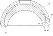
图6为图1所示内衬与外壳结合的剖视图,其中内衬正确地位于外壳内。Fig. 6 is a cross-sectional view of the liner and shell shown in Fig. 1, where the liner is correctly positioned in the shell.
图7为根据本发明的另一个实施例的内衬的透视图。Figure 7 is a perspective view of a liner according to another embodiment of the present invention.
图8示出了根据本发明的一个实施例的内衬和外壳的使用方法的流程图。Figure 8 shows a flowchart of a method of using a liner and shell according to one embodiment of the present invention.
图9为图1所示内衬的局部剖视图,图中标出了根据本发明的一个实施例的区域之间的多个尺寸。Figure 9 is a partial cross-sectional view of the liner shown in Figure 1 with various dimensions marked between regions according to one embodiment of the present invention.
具体实施方式Detailed ways
通过参考以下的描述和附图最佳地理解本发明的实施例及其优点,其中相同的附图标记用于附图中相同的和对应的部件。Embodiments of the present invention and their advantages are best understood by referring to the following description and drawings, wherein like reference numerals are used for like and corresponding parts in the drawings.
现在参见图1和图2,图中示出了根据本发明的一个实施例的内衬10。内衬10包括内表面(或支承表面)12。如图所示,该实施例中的支承表面12是大致凹形的。支承表面12被设计用于与股骨头(未示出)通过关节连接。内衬10还包括外表面14。外表面14被设计用于贴合到外壳16中(图5和图6)。支承表面12和外表面14连接到在支承表面12与外表面14之间延伸的边缘18。换句话讲,边缘18在支承表面12与外表面14之间。在该实施例中,支承表面12、外表面14和边缘18都由单个片形成。在其他实施例中,这些片可以是模块化的并锁定在一起。Referring now to Figures 1 and 2, there is shown a
仍参见图1和图2,下面将对外表面14进行更详细的描述。外表面14包括锁定部分20、复合弯曲部分22和圆顶部分24。在该实施例中,圆顶部分24包括平坦的顶部24a,这常见于一些现有技术的内衬设计中。然而,应当理解,在一些内衬10中,可以没有平坦的顶部。锁定部分20从边缘18延伸,并且其尺寸和形状适于接合外壳16,如下文所详述。在该实施例中,锁定部分20是锥形壁,但也可以使用其他已知的锁定机构。Still referring to FIGS. 1 and 2 , the
在图1和图2所示的实施例中,复合弯曲部分22包括两个部分:径向部分25和切向部分26。在示出的实施例中,径向部分是弯曲的,而切向部分26是直线。在其他实施例中,切向部分26也可以是弯曲的,但其半径与径向部分的半径不同。如图3所示,该图示出了复合弯曲部分22周围的内衬10的放大视图,锁定部分20在过渡点28处与径向部分25相切。换句话讲,径向部分25从锁定部分20切向地延伸。由于径向部分25与锁定部分20相切,因此锁定部分20与径向部分25之间没有边缘并且具有连续性。径向部分25是弯曲的,具有与锁定部分20相切的圆半径,从而限定它的中心。In the embodiment shown in FIGS. 1 and 2 , the compound curved
如图2所示,复合弯曲部分22从锁定部分20的结束点处开始从锁定部分20延伸。在一些实施例中,没有圆顶部分24,并且复合弯曲部分22一直延伸至内衬10的顶部。As shown in FIG. 2 , the compound curved
现在参见图3,径向部分25在过渡点30处切向地融入到切向部分26中。换句话讲,在过渡点30处,切向部分26从径向部分25切向地延伸。径向部分25在点30处与切向部分相切,使得内衬10上不存在边缘或尖角。切向部分26是直线,它还与圆顶部分24在过渡点32处相切。换句话讲,切向部分26是与径向部分25和圆顶部分24均相切的直线。因为具有与这两个弯曲区域24、25均相切的切向部分26,所以没有边缘或拐角,从而减少了粗糙的表面。在图1-3所示的实施例中,切向部分26是直线。在其他实施例中,切向部分26可以是弯曲的。在其他实施例中,如图7中进一步所述,可以没有切向部分。复合弯曲部分22可以只包括径向部分25。Referring now to FIG. 3 , the
参见图4,示出的内衬10叠加在现有技术内衬(线34)上。从图中可以看到,复合弯曲部分22从现有技术内衬的相应外部34向外延伸。该附加材料用图4中的非阴影部分35表示。当组装两个片时(如以下图5和图6进一步所示),内衬10中的附加材料减小内衬10与外壳16之间的间隙量。Referring to Figure 4, the
在一些实施例中,通过将径向部分25的半径最大化来确定径向部分25的曲率,同时径向部分25的曲率仍能够形成与径向部分25和圆顶部分24均相切的切向部分26。然而,在其他实施例中,其他参数可以确定径向部分25的曲率。In some embodiments, the curvature of
现在参见图5和图6,图中示出了插入外壳16中的内衬10。外壳16包括内表面36和外表面38。外表面38被设计为贴合到外科手术准备的髋臼(未示出)内。内表面36包括锁定部分40,其被设计为与内衬10的锁定部分20相配合。在该实施例中,锁定部分40为锥形体,它与内衬10的锥形锁定部分20相配合。在该实施例中,外壳16和内衬10的锁定部分40、锁定部分20是本领域已知的自锁式锥形体。Referring now to FIGS. 5 and 6 , the
当首先将内衬10引入外壳16中时,如果锁定部分20和锁定部分40未对齐,如图5所示,那么内衬10会“浮”在外壳16内,而不会在外壳16内齐平。换句话讲,内衬10的边缘18不与外壳16的边缘42齐平。这允许使用者确保内衬10的锁定部分20、锁定部分40与外壳16在放置之前对齐。如上所述,复合弯曲部分22包括附加的材料(图4的非阴影部分35),从而减小了内衬10与外壳16之间的间隙。因此,除非外壳16和内衬10的锁定部分20和锁定部分40对齐,否则复合弯曲部分22会与外壳邻接,以防止内衬陷入某个位置。内衬10和外壳16对齐后,锁定部分20、锁定部分40接合,并且内衬10的锁定部分20与外壳16的锁定部分40完全呈锥形接触,内衬10和外壳16可以完全如图6所示放置。如果内衬10完全置于外壳16中,内衬10的边缘18平行于外壳16的边缘42。When the
图7示出了本发明的另一个实施例。该实施例包括内衬50。内衬50包括锁定部分52、复合弯曲部分54和圆顶部分56。在该实施例中,复合弯曲部分54包括单个弯曲部分58。换句话讲,没有如上文图1-6的实施例中所述的直线切向部分。复合弯曲部分54的弯曲部分58从锁定部分的结束点55延伸。在一些实施例中,没有圆顶部分56,并且复合弯曲部分54延伸至内衬10的顶部。在有圆顶部分56的其他实施例中,复合弯曲部分54在点59处融入圆顶部分56中。在该实施例中,弯曲部分58从锁定部分52和圆顶部分56切向地延伸。Figure 7 shows another embodiment of the present invention. This embodiment includes a
现在参见图8,图中示出了本发明的一个实施例的使用方法。在步骤s60,将外壳16插入髋臼(未示出)中。将内衬10、内衬50置于外壳中(s62)。如果内衬10、内衬50不固定,那么使用者旋转内衬10、内衬50(步骤s64),直至其如图6所示滑入外壳16中。在一些实施例中,可以在将内衬10、内衬50插入外壳中之后完成步骤s60。换句话讲,内衬/外壳组合可以在手术室中进行组装,也可以预先组装在整体外壳中,其中具有预先组装在一起的内衬和外壳。使用者可以是在手术过程中组装外壳和内衬的外科医生,也可以是对装置进行预组装,然后将外壳和内衬组件递送至外科医生的某个人。Referring now to FIG. 8, there is shown a method of using an embodiment of the present invention. At step s60, the
现在参见图9,图中示出了内衬10的局部剖视图。在该实施例中,内衬10具有外表面14,其包括锁定部分20、复合弯曲部分22和圆顶部分24。复合弯曲部分22包括两个部分:径向部分25和切向部分26。图9示出的一个实施例列出了这些部分和区域的多个尺寸。如图所示,锁定部分20具有介于约0.250英寸和0.300英寸之间的高度70。锁定部分20具有介于约1.2英寸和2.0英寸之间的锥度量规直径72和介于约0.190英寸和2.20英寸之间的锥度量规位置74。锁定部分20还具有介于5度和6度之间的锥角76。Referring now to FIG. 9, a partial cross-sectional view of
径向部分25具有介于0.250英寸和0.750英寸之间的过渡半径78。切向的平坦部分以介于约9.0度和10.0度之间的角度80延伸,并具有介于约0.10英寸和0.15英寸之间的长度82。
虽然本发明易受各种修改形式和替代形式的影响,但其具体实施例已在附图中以举例的方式示出,并且本文将详细说明。然而应当理解,本文无意将本发明限制为所公开的具体形式,而是相反,本发明的目的在于涵盖落入如由所附权利要求限定的本发明的精神和范围内的所有修改形式、等同形式和替代形式。While the invention is susceptible to various modifications and substitutions, specific embodiments thereof have been shown by way of example in the drawings and herein will be described in detail. It should be understood, however, that there is no intent to limit the invention to the particular forms disclosed, but on the contrary, the intention is to cover all modifications, equivalents and other modifications falling within the spirit and scope of the invention as defined by the appended claims. forms and alternative forms.
Claims (9)
Priority Applications (1)
| Application Number | Priority Date | Filing Date | Title |
|---|---|---|---|
| CN201610537083.7ACN106037995B (en) | 2011-09-30 | 2012-09-28 | The bite-resistant acetabular bone liner of self centering |
Applications Claiming Priority (3)
| Application Number | Priority Date | Filing Date | Title |
|---|---|---|---|
| US201161541135P | 2011-09-30 | 2011-09-30 | |
| US61/541,135 | 2011-09-30 | ||
| US61/541135 | 2011-09-30 |
Related Child Applications (1)
| Application Number | Title | Priority Date | Filing Date |
|---|---|---|---|
| CN201610537083.7ADivisionCN106037995B (en) | 2011-09-30 | 2012-09-28 | The bite-resistant acetabular bone liner of self centering |
Publications (2)
| Publication Number | Publication Date |
|---|---|
| CN103027766Atrue CN103027766A (en) | 2013-04-10 |
| CN103027766B CN103027766B (en) | 2016-08-17 |
Family
ID=48015517
Family Applications (2)
| Application Number | Title | Priority Date | Filing Date |
|---|---|---|---|
| CN201610537083.7AActiveCN106037995B (en) | 2011-09-30 | 2012-09-28 | The bite-resistant acetabular bone liner of self centering |
| CN201210370730.1AActiveCN103027766B (en) | 2011-09-30 | 2012-09-28 | Self-centering anti-occlusion acetabular liner |
Family Applications Before (1)
| Application Number | Title | Priority Date | Filing Date |
|---|---|---|---|
| CN201610537083.7AActiveCN106037995B (en) | 2011-09-30 | 2012-09-28 | The bite-resistant acetabular bone liner of self centering |
Country Status (4)
| Country | Link |
|---|---|
| JP (4) | JP6095928B2 (en) |
| CN (2) | CN106037995B (en) |
| AU (1) | AU2012227336B2 (en) |
| ZA (1) | ZA201207261B (en) |
Families Citing this family (1)
| Publication number | Priority date | Publication date | Assignee | Title |
|---|---|---|---|---|
| CN110495974B (en)* | 2019-09-30 | 2025-06-27 | 优适医疗科技(苏州)有限公司 | New dual-motion hip prosthesis |
Citations (8)
| Publication number | Priority date | Publication date | Assignee | Title |
|---|---|---|---|---|
| US5919236A (en)* | 1996-08-24 | 1999-07-06 | Cerasiv Gmbh - Innovatives Keramik Engineering | Joint prosthesis |
| EP1133958A1 (en)* | 2000-03-15 | 2001-09-19 | Depuy Orthopaedics, Inc. | Prosthetic cup assembly which includes components possessing self-locking taper |
| US6712857B1 (en)* | 1999-06-02 | 2004-03-30 | Australian Surgical Design And Manufacture Pty Limited | Acetabular component of total hip replacement assembly |
| US20060048461A1 (en)* | 2004-09-06 | 2006-03-09 | Jones Dennis A | Connectors for roofs |
| WO2006048461A2 (en)* | 2004-11-08 | 2006-05-11 | Centre National De La Recherche Scientifique (Cnrs) | Acetabular prosthesis to be fixed without cement |
| EP1728489A1 (en)* | 2005-06-03 | 2006-12-06 | Mathys AG Bettlach | Hip endoprosthesis with acetabular having sealed bores |
| CN1929796A (en)* | 2003-12-22 | 2007-03-14 | 普鲁斯外科植入物有限公司 | Joint socket for a hip endoprosthesis |
| EP1806112A1 (en)* | 2006-01-10 | 2007-07-11 | Thomas Siebel | Implant for forming an acetabular cup |
Family Cites Families (9)
| Publication number | Priority date | Publication date | Assignee | Title |
|---|---|---|---|---|
| ES8704076A1 (en)* | 1984-10-17 | 1987-04-01 | Sostegni Giuliano | Hip prosthesis with a member for damping mechanical stresses. |
| DE19701536A1 (en)* | 1996-08-24 | 1998-02-26 | Cerasiv Gmbh | Joint prosthesis |
| WO2000074604A1 (en)* | 1999-06-02 | 2000-12-14 | Australian Surgical Design And Manufacture Pty Limited | Acetabular component of total hip replacement assembly |
| US7326253B2 (en)* | 2001-11-16 | 2008-02-05 | Depuy Products, Inc. | Prosthetic cup assembly having increased assembly congruency |
| US7115145B2 (en)* | 2003-07-03 | 2006-10-03 | Zimmer, Inc. | Acetabular component |
| JP5296667B2 (en)* | 2006-03-20 | 2013-09-25 | スミス アンド ネフュー インコーポレーテッド | Acetabular cup assembly for multiple bearing elements |
| US20070239283A1 (en)* | 2006-04-11 | 2007-10-11 | Berger Richard A | Acetabular cup conversion ring |
| EP2086470B1 (en)* | 2006-11-17 | 2016-12-14 | Scyon Orthopaedics AG | Wear-reducing geometry of articulations in total joint replacements |
| JP5571580B2 (en)* | 2008-01-30 | 2014-08-13 | ジンマー,インコーポレイティド | Low rigidity orthopedic parts |
- 2012
- 2012-09-26AUAU2012227336Apatent/AU2012227336B2/enactiveActive
- 2012-09-27ZAZA2012/07261Apatent/ZA201207261B/enunknown
- 2012-09-28CNCN201610537083.7Apatent/CN106037995B/enactiveActive
- 2012-09-28CNCN201210370730.1Apatent/CN103027766B/enactiveActive
- 2012-09-28JPJP2012216146Apatent/JP6095928B2/enactiveActive
- 2017
- 2017-02-15JPJP2017025750Apatent/JP6367396B2/enactiveActive
- 2018
- 2018-07-02JPJP2018125920Apatent/JP6640286B2/enactiveActive
- 2019
- 2019-12-24JPJP2019232571Apatent/JP6830995B2/enactiveActive
Patent Citations (8)
| Publication number | Priority date | Publication date | Assignee | Title |
|---|---|---|---|---|
| US5919236A (en)* | 1996-08-24 | 1999-07-06 | Cerasiv Gmbh - Innovatives Keramik Engineering | Joint prosthesis |
| US6712857B1 (en)* | 1999-06-02 | 2004-03-30 | Australian Surgical Design And Manufacture Pty Limited | Acetabular component of total hip replacement assembly |
| EP1133958A1 (en)* | 2000-03-15 | 2001-09-19 | Depuy Orthopaedics, Inc. | Prosthetic cup assembly which includes components possessing self-locking taper |
| CN1929796A (en)* | 2003-12-22 | 2007-03-14 | 普鲁斯外科植入物有限公司 | Joint socket for a hip endoprosthesis |
| US20060048461A1 (en)* | 2004-09-06 | 2006-03-09 | Jones Dennis A | Connectors for roofs |
| WO2006048461A2 (en)* | 2004-11-08 | 2006-05-11 | Centre National De La Recherche Scientifique (Cnrs) | Acetabular prosthesis to be fixed without cement |
| EP1728489A1 (en)* | 2005-06-03 | 2006-12-06 | Mathys AG Bettlach | Hip endoprosthesis with acetabular having sealed bores |
| EP1806112A1 (en)* | 2006-01-10 | 2007-07-11 | Thomas Siebel | Implant for forming an acetabular cup |
Also Published As
| Publication number | Publication date |
|---|---|
| JP2017080600A (en) | 2017-05-18 |
| JP6640286B2 (en) | 2020-02-05 |
| JP6095928B2 (en) | 2017-03-15 |
| AU2012227336B2 (en) | 2015-03-26 |
| ZA201207261B (en) | 2014-09-25 |
| AU2012227336A1 (en) | 2013-04-18 |
| CN106037995B (en) | 2018-03-30 |
| CN103027766B (en) | 2016-08-17 |
| JP2020044411A (en) | 2020-03-26 |
| JP6830995B2 (en) | 2021-02-17 |
| JP6367396B2 (en) | 2018-08-01 |
| CN106037995A (en) | 2016-10-26 |
| JP2013078583A (en) | 2013-05-02 |
| JP2018143863A (en) | 2018-09-20 |
Similar Documents
| Publication | Publication Date | Title |
|---|---|---|
| US10105230B2 (en) | Self-centering, anti-seizing acetabular liner | |
| US9713531B2 (en) | Deflection resistant acetabular cup | |
| US20070142921A1 (en) | Acetabular cup with rigid fasteners | |
| AU2005202696B2 (en) | Extended radius prosthesis and associated method | |
| WO2018063872A1 (en) | Acetabular shell and liner system | |
| JP6830995B2 (en) | liner | |
| AU2017203409B2 (en) | Self-centering, anti-seizing acetabular liner |
Legal Events
| Date | Code | Title | Description |
|---|---|---|---|
| C06 | Publication | ||
| PB01 | Publication | ||
| C10 | Entry into substantive examination | ||
| SE01 | Entry into force of request for substantive examination | ||
| C14 | Grant of patent or utility model | ||
| GR01 | Patent grant |