CN103027677A - Mapping catheter with spiral electrode assembly - Google Patents
Mapping catheter with spiral electrode assemblyDownload PDFInfo
- Publication number
- CN103027677A CN103027677ACN2012103707886ACN201210370788ACN103027677ACN 103027677 ACN103027677 ACN 103027677ACN 2012103707886 ACN2012103707886 ACN 2012103707886ACN 201210370788 ACN201210370788 ACN 201210370788ACN 103027677 ACN103027677 ACN 103027677A
- Authority
- CN
- China
- Prior art keywords
- dilator
- conduit according
- elongate body
- respect
- catheter
- Prior art date
- Legal status (The legal status is an assumption and is not a legal conclusion. Google has not performed a legal analysis and makes no representation as to the accuracy of the status listed.)
- Granted
Links
- 238000013507mappingMethods0.000titleabstractdescription29
- 230000033001locomotionEffects0.000claimsdescription21
- 230000008602contractionEffects0.000claimsdescription7
- 230000008859changeEffects0.000claimsdescription6
- 230000004044responseEffects0.000claims2
- 238000000034methodMethods0.000description18
- 230000000694effectsEffects0.000description11
- 210000005242cardiac chamberAnatomy0.000description10
- 239000000463materialSubstances0.000description10
- 210000001519tissueAnatomy0.000description10
- 230000006835compressionEffects0.000description9
- 238000007906compressionMethods0.000description9
- 229920002614Polyether block amidePolymers0.000description5
- 239000004814polyurethaneSubstances0.000description5
- 229920002635polyurethanePolymers0.000description5
- 230000007246mechanismEffects0.000description4
- 229910001220stainless steelInorganic materials0.000description4
- 239000010935stainless steelSubstances0.000description4
- 206010047302ventricular tachycardiaDiseases0.000description4
- 239000004593EpoxySubstances0.000description3
- 239000004642PolyimideSubstances0.000description3
- 238000002679ablationMethods0.000description3
- 230000004913activationEffects0.000description3
- WYTGDNHDOZPMIW-RCBQFDQVSA-NalstonineNatural productsC1=CC2=C3C=CC=CC3=NC2=C2N1C[C@H]1[C@H](C)OC=C(C(=O)OC)[C@H]1C2WYTGDNHDOZPMIW-RCBQFDQVSA-N0.000description3
- 238000010276constructionMethods0.000description3
- 210000005003heart tissueAnatomy0.000description3
- 230000007935neutral effectEffects0.000description3
- 229920001721polyimidePolymers0.000description3
- 239000000523sampleSubstances0.000description3
- 239000004809TeflonSubstances0.000description2
- 229920006362Teflon®Polymers0.000description2
- 230000000747cardiac effectEffects0.000description2
- 229910003460diamondInorganic materials0.000description2
- 239000010432diamondSubstances0.000description2
- 230000005684electric fieldEffects0.000description2
- 239000003292glueSubstances0.000description2
- 210000002837heart atriumAnatomy0.000description2
- WABPQHHGFIMREM-UHFFFAOYSA-Nlead(0)Chemical compound[Pb]WABPQHHGFIMREM-UHFFFAOYSA-N0.000description2
- 230000003902lesionEffects0.000description2
- 230000033764rhythmic processEffects0.000description2
- 230000008961swellingEffects0.000description2
- 239000000853adhesiveSubstances0.000description1
- 230000001070adhesive effectEffects0.000description1
- 210000003484anatomyAnatomy0.000description1
- 238000013459approachMethods0.000description1
- 206010003119arrhythmiaDiseases0.000description1
- 210000001367arteryAnatomy0.000description1
- 230000000712assemblyEffects0.000description1
- 238000000429assemblyMethods0.000description1
- 230000008901benefitEffects0.000description1
- 230000002457bidirectional effectEffects0.000description1
- 239000011248coating agentSubstances0.000description1
- 238000000576coating methodMethods0.000description1
- 230000000916dilatatory effectEffects0.000description1
- 230000006870functionEffects0.000description1
- 238000003780insertionMethods0.000description1
- 230000037431insertionEffects0.000description1
- 210000005246left atriumAnatomy0.000description1
- 238000005259measurementMethods0.000description1
- 239000002184metalSubstances0.000description1
- 238000012986modificationMethods0.000description1
- 230000004048modificationEffects0.000description1
- HLXZNVUGXRDIFK-UHFFFAOYSA-Nnickel titaniumChemical compound[Ti].[Ti].[Ti].[Ti].[Ti].[Ti].[Ti].[Ti].[Ti].[Ti].[Ti].[Ni].[Ni].[Ni].[Ni].[Ni].[Ni].[Ni].[Ni].[Ni].[Ni].[Ni].[Ni].[Ni].[Ni]HLXZNVUGXRDIFK-UHFFFAOYSA-N0.000description1
- 229910001000nickel titaniumInorganic materials0.000description1
- 231100000252nontoxicToxicity0.000description1
- 230000003000nontoxic effectEffects0.000description1
- 230000037361pathwayEffects0.000description1
- 230000002093peripheral effectEffects0.000description1
- 239000004033plasticSubstances0.000description1
- 229920003023plasticPolymers0.000description1
- 230000003014reinforcing effectEffects0.000description1
- 238000000926separation methodMethods0.000description1
- 239000007787solidSubstances0.000description1
- 125000006850spacer groupChemical group0.000description1
- 230000000638stimulationEffects0.000description1
- 230000001225therapeutic effectEffects0.000description1
- 238000002560therapeutic procedureMethods0.000description1
- 210000003813thumbAnatomy0.000description1
- 230000007704transitionEffects0.000description1
- 238000013519translationMethods0.000description1
- 210000005166vasculatureAnatomy0.000description1
- 210000003462veinAnatomy0.000description1
Images


Classifications
- A—HUMAN NECESSITIES
- A61—MEDICAL OR VETERINARY SCIENCE; HYGIENE
- A61B—DIAGNOSIS; SURGERY; IDENTIFICATION
- A61B5/00—Measuring for diagnostic purposes; Identification of persons
- A61B5/24—Detecting, measuring or recording bioelectric or biomagnetic signals of the body or parts thereof
- A61B5/25—Bioelectric electrodes therefor
- A61B5/279—Bioelectric electrodes therefor specially adapted for particular uses
- A61B5/28—Bioelectric electrodes therefor specially adapted for particular uses for electrocardiography [ECG]
- A61B5/283—Invasive
- A61B5/287—Holders for multiple electrodes, e.g. electrode catheters for electrophysiological study [EPS]
Landscapes
- Health & Medical Sciences (AREA)
- Life Sciences & Earth Sciences (AREA)
- Medical Informatics (AREA)
- Molecular Biology (AREA)
- Cardiology (AREA)
- Biophysics (AREA)
- Pathology (AREA)
- Engineering & Computer Science (AREA)
- Biomedical Technology (AREA)
- Heart & Thoracic Surgery (AREA)
- Physiology (AREA)
- Physics & Mathematics (AREA)
- Surgery (AREA)
- Animal Behavior & Ethology (AREA)
- General Health & Medical Sciences (AREA)
- Public Health (AREA)
- Veterinary Medicine (AREA)
- Measurement And Recording Of Electrical Phenomena And Electrical Characteristics Of The Living Body (AREA)
- Media Introduction/Drainage Providing Device (AREA)
- Electrotherapy Devices (AREA)
- Surgical Instruments (AREA)
Abstract
Translated fromChinese
Description
Translated fromChinese技术领域technical field
本发明涉及导管,该导管用于利用接触电极的组件快速产生心脏腔室的心电图,以便获得指示腔室电活动和可选地腔室几何形状的信息。The present invention relates to a catheter for rapidly producing an electrocardiogram of a chamber of the heart using an assembly of contact electrodes in order to obtain information indicative of chamber electrical activity and optionally chamber geometry.
背景技术Background technique
心律失常是导致死亡的主要原因,最常见的一种心律失常是室性心动过速(VT)。在大多数患者中,VT起源于位于靠近心脏腔室内表面处的1mm至2mm病灶。对VT的治疗方法之一包括标测心脏的电通路以定位病灶,然后消融活性部位。Cardiac arrhythmias are a leading cause of death, the most common of which is ventricular tachycardia (VT). In most patients, VT originates from a 1 mm to 2 mm lesion located close to the inner surface of the heart chamber. One approach to the treatment of VT involves mapping the electrical pathways of the heart to localize the lesion, followed by ablation of the active site.
共同转让的美国专利No.5,546,951、美国专利申请No.08/793,371和PCT申请WO 96/05768公开了用于感测随心脏内的精确位置而变化的心脏组织的电性质(例如局部激动时间)的方法,这些专利全文以引用方式并入本文中。利用在其远端头中具有电传感器和位置传感器的导管,用进入心脏中的一个或多个导管来采集数据。基于这些数据形成心脏电活动图的方法在分别提交于1998年7月24日和1999年7月22日的共同转让的美国专利申请No.09/122,137和No.09/357,559中有所公开,这两份申请也以引用方式全文并入本文中。如这些申请中所指出的那样,优选地首先在心脏内表面上的约10个至约20个点处测量位置和电活动。这些数据点因此通常足以产生具有令人满意的质量的心脏表面的初步再现或初步图。初步图常常与取自额外的点处的数据结合,以便产生更全面的心脏电活动图。在临床背景下,并不少见的是在100个或以上的位点收集数据以产生详细而全面的心脏腔室电活动图。所产生的详细的图可接着作为基础用于决定例如组织消融的治疗行动过程,以改变心脏电活动的传播和恢复正常心律。Commonly assigned U.S. Patent No. 5,546,951, U.S. Patent Application No. 08/793,371, and PCT Application WO 96/05768 disclose methods for sensing electrical properties of cardiac tissue (such as local activation times) that vary with precise locations within the heart. methods of these patents, which are incorporated herein by reference in their entirety. Data is acquired with one or more catheters inserted into the heart using a catheter with electrical and position sensors in its distal tip. Methods for forming a map of the electrical activity of the heart based on these data are disclosed in commonly assigned U.S. Patent Application Nos. 09/122,137 and 09/357,559, filed July 24, 1998, and July 22, 1999, respectively, Both applications are also incorporated herein by reference in their entirety. As noted in these applications, the position and electrical activity are preferably first measured at about 10 to about 20 points on the inner surface of the heart. These data points are therefore usually sufficient to produce a preliminary reconstruction or map of the heart surface of satisfactory quality. The preliminary map is often combined with data taken at additional points in order to produce a more comprehensive map of the heart's electrical activity. In a clinical setting, it is not uncommon for data to be collected at 100 or more sites to produce a detailed and comprehensive map of the electrical activity of the cardiac chambers. The resulting detailed map can then be used as a basis for deciding on a course of therapeutic action such as tissue ablation to alter the propagation of the heart's electrical activity and restore normal heart rhythm.
包含位置传感器的导管可用于确定心脏表面上的点的轨线。这些轨线可用于推断诸如组织收缩性的运动特性。如美国专利No.5,738,096中所公开的那样,当在心脏中足够多的点处采集轨线信息时,可构建描绘这样的运动特性的图,该专利以引用方式全文并入本文中。Catheters containing position sensors can be used to determine trajectories of points on the surface of the heart. These trajectories can be used to infer motion properties such as tissue contractility. A map characterizing such motion can be constructed when trajectory information is acquired at a sufficient number of points in the heart, as disclosed in US Patent No. 5,738,096, which is hereby incorporated by reference in its entirety.
通常将在远端头处或附近包含电传感器的导管推进到心脏中的某点处,用传感器接触组织并采集该点处的数据,通过这种方式来测量心脏中该点处的电活动。使用仅包含单个远端头电极的导管标测心脏腔室的一个缺点是在对于腔室总体的详细图所需的必要数量的点上逐点采集数据需要的时间较长。因此,已开发出多电极导管以同时在心脏腔室中的多个点处测量电活动。Electrical activity at a point in the heart is typically measured by advancing a catheter containing an electrical sensor at or near the distal tip to a point in the heart where the sensor contacts tissue and collects data at that point. One disadvantage of using a catheter containing only a single distal tip electrode to map cardiac chambers is the time required to acquire data point-by-point at the necessary number of points for a detailed map of the chamber population. Therefore, multi-electrode catheters have been developed to simultaneously measure electrical activity at multiple points in the chambers of the heart.
美国专利No.5,487,391涉及用于导出和显示心脏中的电事件的传播速度的系统和方法,该专利说明了本领域存在的接触方法。在'391专利所公开的系统中,电探针为采用篮子形状的三维结构。在图示实施例中,篮子由8个脊骨构成,每个脊骨承载8个电极,以用于探针中的总共64个电极。篮子结构被设计成使得当展开时其电极紧贴心内膜表面保持紧密接触。US Patent No. 5,487,391, which relates to systems and methods for deriving and displaying the propagation velocity of electrical events in the heart, describes contact methods that exist in the art. In the system disclosed in the '391 patent, the electrical probe is a three-dimensional structure in the shape of a basket. In the illustrated embodiment, the basket consists of 8 spines, each carrying 8 electrodes, for a total of 64 electrodes in the probe. The basket structure is designed so that when deployed its electrodes remain in intimate contact against the endocardial surface.
授予Triedman等人的美国专利No.5,848,972公开了一种用于使用多电极导管进行心内膜激动标测的方法。在'972专利的方法中,多电极导管被推进至心脏的腔室中,该导管优选地为得自Cordis-Webster公司(加利福尼亚州鲍德温帕克)(Cordis-Webster(Baldwin Park,Calif.))的Webster-Jenkins.TM.50电极篮式导管(50-electrode Webster-Jenkins.TM.basketcatheter)。获得前后位(AP)和侧向荧光图以确定电极中的每一个的位置和取向。从接触心脏表面的电极中的每一个记录相对于诸如来自体表ECG的窦性心律中的P波的起点的时间基准的电描记图。US Patent No. 5,848,972 to Triedman et al. discloses a method for endocardial activation mapping using a multi-electrode catheter. In the method of the '972 patent, a multi-electrode catheter is advanced into a chamber of the heart, preferably a Catheter® Catheter from Cordis-Webster (Baldwin Park, Calif.) Webster-Jenkins.TM.50 electrode basket catheter (50-electrode Webster-Jenkins.TM.basketcatheter). Anteroposterior (AP) and lateral fluoroscopic views were obtained to determine the position and orientation of each of the electrodes. An electrogram is recorded from each of the electrodes contacting the surface of the heart relative to a time reference such as the onset of the P wave in sinus rhythm from a surface ECG.
授予Beatty等人的美国专利No.5,297,549(“Beatty方法”)公开了用于标测心脏腔室的电势分布的方法和设备,该专利的公开内容以引用方式并入本文中。在Beatty方法中,心内多电极标测导管组件被插入心脏中。该标测导管组件包括多电极组件,其带有一体的基准电极或优选地配对的基准导管。在使用中,电极以基本上球形组件的形式被部署。电极组件由基准电极或由与心内膜表面接触的基准导管在空间上以心内膜表面上的点为基准。据说优选的电极组件导管承载至少24个单独的电极位点。另外,Beatty方法需要知道组件上的每个电极位点的位置并且知道心脏几何形状。这些位置优选地通过阻抗体积描记方法来确定。US Patent No. 5,297,549 to Beatty et al. ("Beatty Method") discloses a method and apparatus for mapping the electrical potential distribution of cardiac chambers, the disclosure of which is incorporated herein by reference. In the Beatty method, an intracardiac multi-electrode mapping catheter assembly is inserted into the heart. The mapping catheter assembly includes a multi-electrode assembly with an integral reference electrode or preferably a mated reference catheter. In use, the electrodes are deployed in a substantially spherical assembly. The electrode assembly is spatially referenced to a point on the endocardial surface by a reference electrode or by a reference catheter in contact with the endocardial surface. A preferred electrode assembly catheter is said to carry at least 24 individual electrode sites. Additionally, the Beatty method requires knowledge of the location of each electrode site on the assembly and knowledge of the heart geometry. These positions are preferably determined by impedance plethysmography.
授予Kagan等人的美国专利No.5,311,866公开了一种包括限定多个电极位点的电极组件的心脏标测导管组件。标测导管组件还包括接纳基准导管的内腔,基准导管具有可用于探测心壁的远端头电极组件。在优选构造中,标测导管包括绝缘线的编织物,编织物中优选地具有24至64根线,每根线被用于形成电极位点。据说导管可容易地定位在心脏中以用于从第一组非接触电极位点和/或第二组接触电极位点采集电活动信息。US Patent No. 5,311,866 to Kagan et al. discloses a cardiac mapping catheter assembly including an electrode assembly defining a plurality of electrode sites. The mapping catheter assembly also includes a lumen for receiving a fiducial catheter having a distal tip electrode assembly operable to probe the heart wall. In a preferred construction, the mapping catheter comprises a braid of insulated wires, preferably with 24 to 64 wires in the braid, each wire being used to form an electrode site. The catheter is said to be easily positionable in the heart for collecting electrical activity information from the first set of non-contacting electrode sites and/or the second set of contacting electrode sites.
授予Goldreyer的美国专利No.5,385,146和No.5,450,846公开了据说可用于标测心脏内的电生理活动的导管。导管主体具有适于传输用于对心脏起搏的刺激脉冲的远端头或用于对接触远端头的组织进行消融的消融电极。导管还包括至少一对正交电极以产生指示正交电极附近的局部心脏电活动的差分信号。US Patent Nos. 5,385,146 and 5,450,846 to Goldreyer disclose catheters that are said to be useful for mapping electrophysiological activity within the heart. The catheter body has a distal tip adapted to deliver stimulation pulses for pacing the heart or an ablation electrode for ablating tissue contacting the distal tip. The catheter also includes at least one pair of orthogonal electrodes to generate a differential signal indicative of local cardiac electrical activity in the vicinity of the orthogonal electrodes.
授予Budd等人的美国专利No.5,662,108公开了一种用于测量心脏腔室中的电生理数据的方法。该方法部分地涉及将一组有源电极和无源电极定位在心脏中;向有源电极供应电流,从而在心脏腔室中产生电场;以及在所述无源电极位点处测量所述电场。在所公开的实施例中的一个中,无源电极包含在位于球囊导管的可扩张球囊上的组件中。在优选实施例中,据说该组件具有60至64个电极。US Patent No. 5,662,108 to Budd et al. discloses a method for measuring electrophysiological data in cardiac chambers. The method involves, in part, positioning a set of active electrodes and passive electrodes in the heart; supplying current to the active electrodes, thereby generating an electric field in a chamber of the heart; and measuring the electric field at the passive electrode sites . In one of the disclosed embodiments, the passive electrodes are included in an assembly on an expandable balloon of a balloon catheter. In a preferred embodiment, the assembly is said to have 60 to 64 electrodes.
最近常见的操作是使用四极导管来标测心脏的各个腔室。此外,导管在整个腔室中四处缓慢移动,直到可以一起外推足够多的点以提供足够的信息。It is common practice these days to use a quadrupole catheter to map the chambers of the heart. In addition, the catheter is slowly moved around throughout the chamber until enough points can be extrapolated together to provide sufficient information.
因此,已经提出各种方法来增加采集心电图的速度。然而,仍然需要一种标测导管,该导管通过提供能扩张且用一次蜿蜒移动来捕获心脏腔室结构的远端电极组件而减少过程时间。例如,通过轻微的旋转或平移运动,该组件应能够充分接触心壁以便能够构建完整的腔室图。该组件应具有合适的形状、尺寸和柔韧性以避免心脏组织隆起,同时能够跟随心脏收缩运动。Therefore, various methods have been proposed to increase the speed of acquiring an electrocardiogram. However, there remains a need for a mapping catheter that reduces procedure time by providing a distal electrode assembly that expands and captures heart chamber structures with one serpentine movement. For example, with a slight rotational or translational movement, the component should be able to contact the heart wall sufficiently to be able to construct a complete chamber map. The component should have the proper shape, size and flexibility to avoid swelling of the heart tissue, while being able to follow the systolic movement of the heart.
发明内容Contents of the invention
本发明涉及一种具有标测电极组件的标测导管,该组件类似带子且成形为螺旋形状。标测电极组件具有形状记忆型支撑结构且载有固定到带子外表面的电极阵列。当标测电极组件扩张时,带子上的多个电极有利地与包括心房或心室在内的心脏腔室的组织壁接触,以便通过用单次蜿蜒移动捕获总体的腔室结构来更快速地标测。通过提供与组织壁接触的相对大的表面积,该组件提供了用于在标测系统中记录的多个位置。而且,通过轻微旋转和平移标测电极组件,应能提供足够数量的位置以获得完整的腔室图。The present invention relates to a mapping catheter having a mapping electrode assembly resembling a belt and shaped in a helical shape. The mapping electrode assembly has a shape memory support structure and carries an electrode array fixed to the outer surface of the belt. When the mapping electrode assembly is expanded, the multiple electrodes on the belt advantageously make contact with the tissue walls of the heart chambers, including the atria or ventricles, to more quickly map by capturing the overall chamber structure with a single serpentine movement. Measurement. By providing a relatively large surface area in contact with the tissue wall, the assembly provides multiple positions for recording in the mapping system. Also, slight rotation and translation of the mapping electrode assembly should provide a sufficient number of positions to obtain a complete chamber map.
在一个实施例中,导管具有细长主体和承载在扩张器上的标测电极组件,该扩张器延伸导管的长度。标测电极组件包括带构件,该带构件被构造成围绕扩张器的螺旋形状,使得扩张器限定组件的纵向轴线。带构件的远端固定到扩张器的远端部分。带构件的近端固定到细长主体。因此,扩张器相对于细长主体的纵向移动导致带构件在扩张构型和收缩构型之间改变其螺旋形状。带构件具有上面固定有多个电极的外表面。带构件的螺旋形状由具有形状记忆能力的至少一个撑条支撑,使得带构件保持其螺旋形状。In one embodiment, the catheter has an elongated body and a mapping electrode assembly carried on a dilator that extends the length of the catheter. The mapping electrode assembly includes a band member configured in a helical shape around the dilator such that the dilator defines a longitudinal axis of the assembly. The distal end of the band member is secured to the distal portion of the dilator. The proximal end of the strap member is secured to the elongated body. Thus, longitudinal movement of the dilator relative to the elongate body causes the band member to change its helical shape between the expanded configuration and the collapsed configuration. The belt member has an outer surface on which a plurality of electrodes are fixed. The helical shape of the belt member is supported by at least one strut having shape memory capability such that the belt member retains its helical shape.
在更详细的实施例中,带构件具有沿螺旋形状面向外的外表面,并且电极安装在外表面上以接触组织壁。电极沿带构件的长度设置,该带构件围绕扩张器盘旋至少约360度,或者约540度。从电极延伸的导线穿过带构件的折叠边缘或“褶边”,然后穿过扩张器的中央内腔朝向控制手柄。In a more detailed embodiment, the band member has an outer surface facing outward in a helical shape, and electrodes are mounted on the outer surface to contact the tissue wall. The electrodes are disposed along the length of the band member, which spirals at least about 360 degrees, alternatively about 540 degrees, around the dilator. The wires extending from the electrodes are threaded through the folded edge, or "frill," of the band member, and then through the central lumen of the dilator toward the control handle.
在另一个详细实施例中,扩张器具有裸露的近端,该近端适于由用户直接操纵以扩张和收缩标测电极组件。扩张器可纵向移动或仅仅旋转以实现组件的扩张和收缩。在另一个详细实施例中,导管包括带有用户界面组件的控制手柄,该控制手柄控制拉线以扩张和收缩标测电极。拉线延伸通过扩张器的中央内腔,并且其远端锚固到扩张器的远端部分。用户界面组件可适于由用户线性致动或旋转致动。在后一情况中,用户界面组件具有将旋转移动转换为纵向移动的部件。In another detailed embodiment, the dilator has a bare proximal end adapted to be directly manipulated by a user to expand and contract the mapping electrode assembly. The dilator can move longitudinally or simply rotate to allow expansion and contraction of the assembly. In another detailed embodiment, the catheter includes a control handle with a user interface assembly that controls the pull wire to expand and contract the mapping electrode. A pull wire extends through the central lumen of the dilator and its distal end is anchored to the distal portion of the dilator. The user interface component may be adapted to be actuated linearly or rotationally by a user. In the latter case, the user interface component has components that convert rotational movement into vertical movement.
附图说明Description of drawings
结合附图阅读以下具体实施方式,将更好地理解本发明的这些和其他特征以及优点。应当理解,选定的结构和特征在某些附图中没有示出,以便更好地呈现其余的结构和特征。These and other features and advantages of the present invention will be better understood from the following detailed description when read in conjunction with the accompanying drawings. It should be understood that selected structures and features are not shown in some of the drawings in order to better present the remaining structures and features.
图1是根据本发明的实施例的导管的透视图。Fig. 1 is a perspective view of a catheter according to an embodiment of the present invention.
图2是根据本发明的实施例处于径向扩张或展开构型的标测电极组件的透视图。2 is a perspective view of a mapping electrode assembly in a radially expanded or deployed configuration according to an embodiment of the invention.
图3是根据本发明的实施例处于径向收缩构型的标测电极组件的透视图。3 is a perspective view of a mapping electrode assembly in a radially contracted configuration according to an embodiment of the invention.
图4是根据本发明实施例的心脏的示意性剖视图,其中示出了本发明的导管插入左心房中。4 is a schematic cross-sectional view of a heart showing insertion of a catheter of the present invention into the left atrium, in accordance with an embodiment of the present invention.
图5A是沿一直径截取的图1的导管的侧剖视图,其包括在导管主体和中间段之间的接合部。5A is a side cross-sectional view of the catheter of FIG. 1 , taken along a diameter, including a junction between the catheter body and the intermediate section.
图5B是沿另一直径截取的图1的导管的侧剖视图,其包括在导管主体和中间段之间的接合部。5B is a side cross-sectional view of the catheter of FIG. 1 taken along another diameter, including a junction between the catheter body and the intermediate section.
图6是沿一直径截取的图1的导管的侧剖视图,其包括中间段的远端。6 is a side cross-sectional view of the catheter of FIG. 1 taken along a diameter, including the distal end of the intermediate section.
图6A是沿A--A线截取的图6的中间段的远端的末端剖视图。FIG. 6A is an end cross-sectional view of the distal end of the intermediate section of FIG. 6 taken along line A--A.
图6B是沿B--B线截取的图6的中间段的远端和外套管的近端的末端剖视图。6B is an end cross-sectional view of the distal end of the intermediate section of FIG. 6 and the proximal end of the overtube, taken along line B--B.
图7是根据本发明的实施例的标测电极组件的带构件的近端和远端的俯视平面图。7 is a top plan view of the proximal and distal ends of the belt member of a mapping electrode assembly in accordance with an embodiment of the present invention.
图8是根据本发明的实施例的标测电极组件的带构件的中段的俯视平面图。8 is a top plan view of a mid-section of a belt member of a mapping electrode assembly in accordance with an embodiment of the present invention.
图9是根据本发明的实施例固定到扩张器的带构件的远端的侧剖视图。9 is a side cross-sectional view of the distal end of a band member secured to a dilator in accordance with an embodiment of the present invention.
图9A是沿线A--A截取的固定到图9的扩张器的带构件的远端的末端剖视图。9A is an end cross-sectional view of the distal end of the band member secured to the dilator of FIG. 9, taken along line A--A.
图10是根据本发明的实施例固定到扩张器的带构件的近端的侧剖视图。10 is a side cross-sectional view of a proximal end of a band member secured to a dilator in accordance with an embodiment of the present invention.
图10A是沿线A--A截取的固定到图10的扩张器的带构件的近端的末端剖视图。10A is an end cross-sectional view of the proximal end of the band member secured to the dilator of FIG. 10, taken along line A--A.
图11是根据本发明的实施例的控制手柄的侧剖视图。11 is a side cross-sectional view of a control handle according to an embodiment of the present invention.
图12是根据本发明的另一个实施例的控制手柄的侧剖视图。12 is a side cross-sectional view of a control handle according to another embodiment of the present invention.
图13是根据本发明的另一个实施例固定到扩张器的带构件的远端的侧剖视图。13 is a side cross-sectional view of the distal end of a band member secured to a dilator according to another embodiment of the present invention.
图13A是沿线A--A截取的固定到图13的扩张器的带构件的近端的末端剖视图。13A is an end cross-sectional view of the proximal end of the band member secured to the dilator of FIG. 13, taken along line A--A.
图14是根据本发明的另一个实施例的导管的俯视平面图。14 is a top plan view of a catheter according to another embodiment of the invention.
图15是根据本发明的一个实施例的控制手柄旋转界面组件的透视图。15 is a perspective view of a control handle rotation interface assembly in accordance with one embodiment of the present invention.
图16是根据本发明的另一个实施例的控制手柄旋转界面组件的透视图。16 is a perspective view of a control handle rotation interface assembly according to another embodiment of the present invention.
图17是根据本发明的另一个实施例的控制手柄线性界面组件的透视图。17 is a perspective view of a control stick linear interface assembly according to another embodiment of the present invention.
具体实施方式Detailed ways
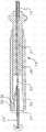
如图1-4所示,本发明包括带有远端头段17的可操纵导管10,远端头段17包括承载多个电极21的远端标测电极组件19,以用于与包括诸如心房或心室的心脏腔室20的腔室的壁组织的多处同时接触。该组件包括柔性平面构件或类似“带子”28的带,带子28被以大致螺旋的构型支撑在扩张器22上。有利地,扩张器可相对于导管被推进和收回以改变螺旋构型,包括径向扩张(图2)和收缩带子28(图3)。带子具有近端24和远端26。近端24固定到外套管27,扩张器22可通过外套管27纵向移动,并且远端26固定到扩张器22的远端25。因此,当扩张器22被操作者相对于外套管推进或收回时,带子28的螺旋构型变化。在导管朝目标位置移动通过患者的脉管的同时,并且在组件19在心脏腔室中展开之前,组件19可采用图2的中立或收缩构型。当组件19到达目标位置时,其展开并操纵成图3和4的扩张构型。As shown in FIGS. 1-4, the present invention includes a
如图5A和图5B所示,导管主体12包括具有单个轴向内腔或中央内腔18的细长管状构造,但如果需要可任选地具有多个内腔。导管主体12具柔性,即可弯曲,但沿其长度基本上不可压缩。导管主体12可具有任何合适的构造,并且可由任何合适的材料制成。目前优选的构造包括由聚氨酯或PEBAX.RTM.(聚醚嵌段酰胺)制成的外壁。外壁包括由不锈钢等制成的嵌入式编织网,以增大导管主体12的抗扭刚度,使得当旋转控制手柄16时导管主体的远端将以相应的方式进行旋转。As shown in Figures 5A and 5B,
导管主体12的外径并非决定性因素,但优选地为不大于约8F(french,弗伦奇),更优选地不大于约7F。同样,外壁的厚度也不是决定性因素,但优选地要足够薄,以使得中央内腔可容纳拉线、导线、传感器电缆和任何其他线材、电缆或管。如果需要,外壁的内表面可衬有补强管(未示出),从而得到改善的扭转稳定性。美国专利No.6,064,905描述并示出了适于与本发明有关的导管主体构造的实例,该专利的全部公开内容以引用的方式并入本文。The outer diameter of
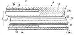
进一步参照图5A和5B,可偏转中间段14包括具有多个内腔的一短截配管15,每个内腔被延伸通过中间段的各个部件占据。在图示实施例中,存在四个内腔32、33、34和35,如图6C中最清楚看出的。用于电极组件19的导线29和用于远端电磁位置传感器38D的电缆36D穿过第一中央内腔32。用于近端电磁位置传感器38P的电缆36P穿过第二内腔33。为了至少单向偏转,第一拉线40A穿过第三离轴内腔34。为了双向偏转,第二拉线40B穿过第四离轴内腔35。With further reference to Figures 5A and 5B, the deflectable
中间段14的多内腔配管15由优选地比导管主体12更柔韧的合适无毒材料制成。合适的材料是编织的聚氨酯或PEBAX,即具有不锈钢或类似材料的嵌入式编织网的聚氨酯或PEBAX。每个内腔的数量和尺寸不是决定性因素,前提是有足够空间来容纳延伸穿过其中的部件。除了针对拉线40A、40B的内腔34、内腔35的定位之外,每个内腔的定位也都不是决定性因素。内腔34、35应为离轴的,并且在直径上彼此相对以沿平面双向偏转。The
导管的可用长度,即可插入体内的部分,可根据需要变化。优选地,可用长度在约110cm至约120cm的范围内。中间段14的长度是可用长度的相对较小部分,并且优选地在约3.5cm至约10cm的范围内,更优选地在约5cm至约6.5cm的范围内。The usable length of the catheter, ie the portion inserted into the body, can vary as needed. Preferably, the useful length is in the range of about 110 cm to about 120 cm. The length of the
图5A和图5B中示出了将导管主体12附接到中间段14上的优选方式。中间段14的近端包括内周凹口,所述内周凹口接纳导管主体12的加劲管31远端的外表面。中间段14和导管主体12通过胶等(例如,聚氨酯)附接。如果需要,可以在导管主体12内加劲管31的远端和中间段14的近端之间设置垫片(未示出),以在导管主体12与中间段的接合部处提供柔韧性的过渡,这使得接合部能够平滑地弯曲而不折叠或扭结。这种垫片的实例在美国专利No.5,964,757中有所描述,该专利的公开内容以引用的方式并入本文中。A preferred manner of attaching the
如图6和6A所示,偏转拉线40A延伸通过导管主体12的中央内腔18并进入中间段14的第三内腔34。另一偏转拉线40B延伸通过中央内腔18并进入中间段14的第四内腔35。偏转拉线的远端通过T型锚81锚定在中间段14的远端附近的配管15的壁上。在中间段14中,每个偏转拉线延伸通过塑料(如Teflon.RTM.)的鞘管83,所述鞘管可防止偏转拉线在中间段14偏转时切入中间段14的配管15的壁中。As shown in FIGS. 6 and 6A , the
如图5A所示,围绕偏转拉线的压缩线圈47从导管主体12的近端延伸至中间段14的近端附近。压缩线圈47由任何合适的金属(如不锈钢)制成。压缩线圈自身紧密地缠绕,以提供柔韧性,即弯曲性,但可抗压缩。压缩线圈的内径优选稍大于拉线的直径。拉线上的Teflon.RTM.涂层使得它们能在压缩线圈内自由滑动。压缩线圈的外表面被柔韧的非导电鞘管49覆盖,以防止压缩线圈与其他部件(如导线和电缆等)之间的接触。非导电鞘管可以由聚酰亚胺管材制成。As shown in FIG. 5A , a
压缩线圈在其近端通过胶接接头(未示出)锚定至导管主体12中的加劲管20的近端,并在其远端通过胶接接头(图5A)在内腔34、35中锚定在中间段14的近端附近。The compression coil is anchored at its proximal end by a glued joint (not shown) to the proximal end of the stiffening
对于远端头段17来说,螺旋形带子电极组件19安装到中间段14的远端。如图6所示,带子28围绕扩张器22延伸在约180和720度之间,优选地至少360度,还更优选约540度。带子具有一致地从扩张器22面向外的外表面39。细长且类似管轴或杆的扩张器形成电极组件19的中心纵向轴线。As with the
带子28可由包括PEBAX的任何合适的材料构成。带子在其远端和近端之间的裸露长度为约10和25cm之间,并且优选约15mm,还更优选约20mm。带子具有约2和10mm之间、并且优选约5和8mm之间的宽度。应当理解,带子可被构造为实心构件、织造构件或纤维网构件,前提是结构为足够刚性且柔韧的,以支撑电极并在扩张和收缩构型中保持大致螺旋形状。
两个形状记忆撑条42A、42B将带子28支撑在扩张器22上并使带子能够弹性且灵活地保持其形状,每个撑条沿带子的纵向边缘43延伸并由沿边缘43折叠的带子的周边长度边缘部分(或“褶边”)45固定和保护。多个细长电极21在折叠的边缘部分之间横向延伸,其数量在约10和50之间,还更优选约20和41之间。在图示实施例中,这些电极等间距地跨越几乎带子的长度并且与扩张器和导管的纵向轴线大致平行。它们以合适的方式(包括例如粘合剂)固定到外表面,使得当组件扩张时它们能容易地接触组织(参见图4)。Two shape memory struts 42A, 42B support the
每个电极21连接到相应的导线29。在图7和8的图示实施例中,用于电极21D的远端部分的导线29D与带子28的一个纵向边缘43并排前进,并且用于电极21P的近端部分的导线29P与带子的另一纵向边缘43并排前进。导线也被镍钛诺撑条42A、42B内侧的带子的褶边45覆盖和保护。Each
带子28的远端26固定到扩张器22的远端部分。如图9、9A所示,在扩张器22中靠近其远端处形成轴向开口或狭槽48D。带子的远端26插入狭槽中,狭槽的尺寸适于贴合带子的宽度但保持形成在每个撑条42A、42B的远端中的远端锚44D。在图示实施例中,每个撑条的远端弯曲成角度(例如约90度)以形成闭锁到扩张器22中的狭槽48D的远端和近端侧的钩。带子的远端横向边缘部分50卷在狭槽48D中,并且锚44D定位在扩张器22的内腔23中。用于电极21D的远端部分的导线29D(为清楚起见仅示出一个)伸入扩张器22的内腔23中,在这里导线朝着控制手柄16向近端穿行。带子26的远端(与远端撑条锚44D一起)用合适的材料(如环氧树脂)固定和密封在狭槽48D中。The
远端位置传感器38D容纳在扩张器22的远端。在图示实施例中,远端位置传感器位于带子28的远端26远侧,但其可根据需要位于另一位置处。用于远端位置传感器38D的电缆36D也朝控制手柄16穿过扩张器22的内腔23。扩张器22的远端头51用合适的材料(如环氧树脂)密封以形成无创末端。
带子28的近端24在其远端附近固定到外套管29。如图6、10和10A所示,在外套管27中形成开放的轴向狭槽48P。带子28的近端24插入狭槽48P中,狭槽48P的尺寸适于贴合带子的宽度但保持形成在每个撑条44A、44B的近端中的锚44P。在图示实施例中,每个撑条的近端弯曲成角度(例如约90度)以形成闭锁到外套管27中的狭槽的远端和近端侧的钩。带子的近端横向边缘部分50P卷在狭槽48P中,并且锚44P定位在扩张器22和外套管27之间的间隙52中。用于电极21P的近端部分的导线29P伸入扩张器22的内腔23中,在这里导线朝着控制手柄16向近端穿行(与用于电极21D的远端部分的导线29D和用于远端位置传感器38D的电缆36D一起)。带子的近端24(与近端撑条锚44P一起)用合适的材料(如环氧树脂)固定和密封在狭槽48P中。The
近端位置传感器38P容纳在中间偏转段14的配管15的远端中。在图6A的图示实施例中,近端位置传感器38P位于外套管27的近端近侧,但其可根据需要位于另一位置处。用于近端位置传感器38P的电缆36P也朝控制手柄16穿过扩张器22的内腔23。The
远端传感器38D的坐标相对于近端传感器38P的坐标而确定,并与关于电极组件19的带子28的曲率/位置的其他已知信息合在一起。该信息用于找到安装在带子上的电极21的位置。然而,应当理解,可以使用其他位置传感器,包括单轴传感器(SAS),例如2010年12月30日提交的名称为“CATHETER WITH SINGLE AXIAL SENSORS”(带有单轴传感器的导管)的美国专利申请No.12/982,765中所描述的那些,该申请的全部公开内容以引用方式并入本文中。The coordinates of the
如描绘的实施例中所示,扩张器22与中间偏转段14和导管主体12大致同轴。如图11所示,扩张器22具有附接到控制手柄16的近端53,如下文进一步描述的,使得扩张器能相对于导管主体12纵向移动,从而扩张和收缩电极组件19。扩张器22包括足够刚性以实现该功能的材料。在一个优选的实施例中,扩张器22包括编织的聚酰亚胺配管,即,包括在两者间具有编织不锈钢网的聚酰亚胺内层和外层的配管,如本领域所熟知的。As shown in the depicted embodiment,
扩张器22相对于导管主体12的纵向移动通过操纵控制手柄16而实现,这种移动导致电极组件18的扩张。如图11所示,控制手柄16包括大致中空的手柄壳体54和可滑动地安装在手柄壳体的远端内的活塞(或拇指控制器)56。导管主体12的近端如本领域熟知的那样由收缩套管(未示出)固定地附接到活塞56的远端,或者通过任何其他合适的方法附接。在控制手柄16内,扩张器22的近端延伸通过活塞56中的通道57并紧固和固定到手柄壳体54。扩张器22通过任何合适的方法(优选用聚氨酯胶等)固定地附接到手柄壳体54。Longitudinal movement of the
在一个实施例中,活塞56长大约2英寸,并且支撑管58和扩张器22在中立位置时在手柄的近端的远侧约0.5英寸且在活塞的近端的近侧约1英寸的位置处附接到手柄壳体54。当电极组件19更紧密地卷绕在扩张器周围(即不扩张)时,活塞在中立位置(带子的远端和近端处于最大间距处)。并且通过向远端移动活塞56,导管主体12和因此中间段14和外套管27以及带子28的近端24向远端移动(缩小带子的近端24和远端26之间的间距)以径向扩张带子(图2)。扩张器22上可设置止挡器60以通过邻接外套管27的远端而限制在带子的末端24、26之间允许的最小间距。导线29D、29P和传感器电缆36D、36P延伸通过扩张器22的内腔23并经过扩张器的近端53,在这里它们附接到在手柄壳体的近端处的(多个)合适的连接器62。In one embodiment, the
在图12的替代实施例中,扩张器22穿过控制手柄16并具有位于控制手柄16的裸露的近端53'近侧。在这种情况下,扩张器可由具有足够抗扭刚度的材料制成,使得当由用户旋转裸露的近端53'时,扩张器的远端25以对应方式旋转。因此,用户可仅仅通过旋转扩张器的裸露近端而径向扩张带子和收缩带子。In the alternative embodiment of FIG. 12 ,
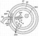
在图13和13A所示的另一个替代实施例中,扩张器的纵向移动可由延伸通过扩张器22的内腔23的第三拉线80来实现。拉线的远端以任何合适的方式(例如T形杆82)锚定在扩张器的远端处或附近。第三拉线80(和用于中间段14的单向或双向偏转的任何其他拉线,例如拉线40A、40B)的操纵可通过任何合适的控制手柄来实现,包括在2009年8月28日提交的名称为“CATHETER WITH MULTI-FUNCTIONAL HANDLEHAVING LINEAR MECHANISM”(带有具有线性机构的多功能手柄的导管)的美国专利申请No.12/550,204和2009年8月28日提交的名称为“CATHETER WITH MULTI-FUNCTIONAL CONTROL HANDLE HAVINGROTATIONAL MECHANISM”(带有具有旋转机构的多功能手柄的导管)的美国专利申请No.12/550,307中所公开的控制手柄,这些申请的全部公开内容以引用方式并入本文中。其中的控制手柄采用将旋转运动转化为平移运动的部件和组件,包括旋转的用户界面,其导致拉线所附接到的从动件的纵向运动。如图14所示,控制手柄16A具有偏转控制旋钮75和旋转组件90。偏转控制旋钮75允许控制中间段14的偏转,并且旋转组件90允许控制电极组件19的扩张和收缩。在图15的图示实施例中,旋转组件90包括外旋转构件202、带有引导狭槽242的内齿轮204和具有轨道232的圆柱形构件207,从动件240在狭槽242的引导下骑跨在轨道232中。构件202的旋转使齿轮204旋转,齿轮204继而借助于狭槽242使从动件240沿轨道滑动。当从动件在轨道中滑动时,附接到从动件的拉线相对于控制手柄纵向移动以致动部件,包括电极组件的扩张和收缩。图16示出了以类似方式操作的旋转组件90'的另一个实施例,所不同的是无齿轮内构件204'通过接纳在小孔252中的销250旋转连接到外旋转构件202'。In another alternative embodiment shown in FIGS. 13 and 13A , the longitudinal movement of the dilator may be accomplished by a
图17示出了合适的旋转组件的又一个实施例。线性界面302通过销303使内圆柱形构件旋转。控制手柄壳体具有轴向狭槽(未示出),该狭槽引导界面302沿控制手柄的纵向轴线的移动。当销303纵向移动时,其在轨道305中滑动并使具有轴向引导狭槽342的外圆柱形构件304旋转,在轴向引导狭槽342中安放有从动件340,从动件340沿形成在内圆柱形构件中的轨道332滑动。当从动件在轨道中滑动时,附接到从动件的拉线相对于控制手柄纵向移动以致动部件,包括用于扩张和收缩的电极组件。Figure 17 shows yet another embodiment of a suitable swivel assembly.
每个位置传感器38P和38D连接到对应的传感器电缆36P和36D,电缆36P和36D在操纵电缆(未示出)内延伸通过扩张器到控制手柄16,并离开控制手柄的近端到容纳电路板(未示出)的传感器控制模块(未示出)。作为另外一种选择,电路板可容纳于控制手柄16内,例如,如美国专利No.6,024,739中所述,该专利的公开内容以引用的方式并入本文。每一根传感器电缆都包括包裹在塑料覆盖鞘管内的多条导线。在传感器控制模块中,将传感器电缆的导线连接到电路板。电路板将从相应的位置传感器接收到的信号放大,然后将其通过在传感器控制模块近端处的传感器连接器以计算机可理解的方式传输给计算机。另外,由于导管被设计成仅用于单次使用,电路板优选包含EPROM芯片,该芯片在导管使用之后大约24小时关断电路板。这可防止导管或至少位置传感器被再次使用。Each
为了使用本发明的导管,电生理学家将导引鞘管引入患者体内,如本领域所熟知的。用于结合本发明的导管使用的合适的导引鞘管为PREFACE.TM.编织导引鞘管(PREFACE.TM.Braided Guiding Sheath),其可从Biosense Webster公司(加利福尼亚州钻石吧)(Biosense Webster,Inc.,Diamond Bar,Calif.)商购获得。导管被引导穿过导引鞘管。导引鞘管内部包覆处于折叠或收缩位置的电极组件19,使得整个导管能沿静脉或动脉向下递送到所需位置。一旦导管的远端到达所需位置,即撤出导引鞘管。然后操纵扩张器22,使得电极组件18的带子28向外弯曲成扩张布置(图4)。在这样的布置中,带子上的电极21接触心脏的组织。如本领域技术人员将认识到的那样,电极组件19可以多种构型完全或部分地扩张,这取决于被标测的心脏的区域的构型。To use the catheter of the present invention, an electrophysiologist introduces an introducing sheath into the patient, as is well known in the art. A suitable guiding sheath for use with the catheter of the present invention is the PREFACE.TM. Braided Guiding Sheath, available from Biosense Webster, Inc. (Diamond Bar, CA) (Biosense Webster , Inc., Diamond Bar, Calif.) commercially available. A catheter is guided through an introducing sheath. The introducer sheath internally covers the
通过提供能用单次蜿蜒移动来扩张和捕获心脏腔室结构的电极组件,本发明的导管增加了采集心电图的速度。例如,通过轻微的旋转或平移运动,该组件应能够充分接触心壁以便能够构建完整的腔室图。该组件应具有合适的形状、尺寸和柔韧性以避免心脏组织隆起,同时能够跟随心脏收缩运动。The catheter of the present invention increases the speed at which an electrocardiogram can be acquired by providing an electrode assembly capable of dilating and capturing cardiac chamber structures with a single serpentine movement. For example, with a slight rotational or translational movement, the component should be able to contact the heart wall sufficiently to be able to construct a complete chamber map. The component should have the proper shape, size and flexibility to avoid swelling of the heart tissue, while being able to follow the systolic movement of the heart.
通过将电极组件18的带子上的电极与远端位置传感器38D和近端位置传感器38P结合使用,电生理学家能标测局部激动时间,这可以在为患者提供治疗过程中指导电生理学家。导管可包括安装在导管主体12上的一个或多个基准环电极,或者可将一个或多个基准电极放置在患者身体外部。通过使用在电极组件19上带有多个电极21的本发明的导管,电生理学家能通过同时测量多个点而获得心脏的真实解剖结构,从而允许他更快速地标测心脏。By using electrodes on the strap of
已结合本发明的当前优选实施例进行了以上描述。本发明所属技术领域内的技术人员将会知道,在不有意背离本发明的原则、精神和范围的前提下,可对所述结构作出更改和修改。在一项实施例中公开的任何特征或结构可根据需要或适当地代替任何其他实施例的其他特征或除任何其他实施例的其他特征之外被并入。如本领域的普通技术人员所理解的那样,附图未必按比例绘制,并且为了清楚起见,所示的多根导线并非旨在必然地表示导管中所用的多个电极。因此,以上描述不应视为仅与所描述和图示的精确结构有关,而应视为符合以下具有最全面和合理范围的权利要求书,并作为权利要求书的支持。The foregoing description has been presented in conjunction with presently preferred embodiments of the invention. Those skilled in the art to which this invention pertains will appreciate that changes and modifications may be made in the structures described without intentionally departing from the principle, spirit and scope of this invention. Any feature or structure disclosed in one embodiment may be incorporated in place of or in addition to other features of any other embodiment as desired or appropriate. As will be understood by those of ordinary skill in the art, the figures are not necessarily drawn to scale, and for clarity, the multiple leads shown are not intended to necessarily represent the multiple electrodes used in the catheter. Accordingly, the above description should not be read as pertaining only to the precise structures described and illustrated, but should be read in accordance with, and as support for, the following claims in their fullest and reasonable scope.
Claims (19)
Applications Claiming Priority (3)
| Application Number | Priority Date | Filing Date | Title |
|---|---|---|---|
| US13/252,891 | 2011-10-04 | ||
| US13/252891 | 2011-10-04 | ||
| US13/252,891US8498686B2 (en) | 2011-10-04 | 2011-10-04 | Mapping catheter with spiral electrode assembly |
Publications (2)
| Publication Number | Publication Date |
|---|---|
| CN103027677Atrue CN103027677A (en) | 2013-04-10 |
| CN103027677B CN103027677B (en) | 2016-09-28 |
Family
ID=46968074
Family Applications (1)
| Application Number | Title | Priority Date | Filing Date |
|---|---|---|---|
| CN201210370788.6AExpired - Fee RelatedCN103027677B (en) | 2011-10-04 | 2012-09-28 | Mapping catheter with spiral electrode assembly |
Country Status (8)
| Country | Link |
|---|---|
| US (1) | US8498686B2 (en) |
| EP (2) | EP2653098B1 (en) |
| JP (1) | JP6109517B2 (en) |
| CN (1) | CN103027677B (en) |
| AU (1) | AU2012227335B2 (en) |
| CA (1) | CA2791588A1 (en) |
| DK (1) | DK2653098T3 (en) |
| ES (1) | ES2531078T3 (en) |
Cited By (8)
| Publication number | Priority date | Publication date | Assignee | Title |
|---|---|---|---|---|
| CN106264715A (en)* | 2015-06-29 | 2017-01-04 | 韦伯斯特生物官能(以色列)有限公司 | There is the conduit of closed loop array with plane internal linear electrode part |
| CN112263320A (en)* | 2020-09-29 | 2021-01-26 | 杭州睿笛生物科技有限公司 | Cervical ablation device |
| US11039772B2 (en) | 2015-06-29 | 2021-06-22 | Biosense Webster (Israel) Ltd. | Catheter with stacked spine electrode assembly |
| US11083400B2 (en) | 2014-11-20 | 2021-08-10 | Biosense Webster (Israel) Ltd. | Catheter with high density electrode spine array |
| US11116436B2 (en) | 2015-06-30 | 2021-09-14 | Biosense Webster (Israel) Ltd. | Catheter having closed electrode assembly with spines of uniform length |
| CN114401687A (en)* | 2019-09-16 | 2022-04-26 | 伯恩森斯韦伯斯特(以色列)有限责任公司 | Catheter with a membrane electrode on an inflatable membrane |
| CN115568919A (en)* | 2022-11-24 | 2023-01-06 | 上海安钛克医疗科技有限公司 | Ultrasound-guided catheter and ultrasound-guided puncture system |
| CN116035586A (en)* | 2023-03-31 | 2023-05-02 | 中国医学科学院阜外医院 | Mapping catheter |
Families Citing this family (56)
| Publication number | Priority date | Publication date | Assignee | Title |
|---|---|---|---|---|
| US6702811B2 (en) | 1999-04-05 | 2004-03-09 | Medtronic, Inc. | Ablation catheter assembly with radially decreasing helix and method of use |
| US7653438B2 (en) | 2002-04-08 | 2010-01-26 | Ardian, Inc. | Methods and apparatus for renal neuromodulation |
| US20140018880A1 (en) | 2002-04-08 | 2014-01-16 | Medtronic Ardian Luxembourg S.A.R.L. | Methods for monopolar renal neuromodulation |
| KR101912960B1 (en) | 2010-10-25 | 2018-10-29 | 메드트로닉 아르디언 룩셈부르크 에스에이알엘 | Catheter Appratuses having Multi-Electrode Arrays for Renal Neuromodulation and Associated Systems and Methods |
| CN107374723B (en) | 2012-05-11 | 2020-08-28 | 美敦力Af卢森堡有限责任公司 | Catheter apparatus |
| US9095321B2 (en) | 2012-11-21 | 2015-08-04 | Medtronic Ardian Luxembourg S.A.R.L. | Cryotherapeutic devices having integral multi-helical balloons and methods of making the same |
| US9179974B2 (en) | 2013-03-15 | 2015-11-10 | Medtronic Ardian Luxembourg S.A.R.L. | Helical push wire electrode |
| US20150073515A1 (en) | 2013-09-09 | 2015-03-12 | Medtronic Ardian Luxembourg S.a.r.I. | Neuromodulation Catheter Devices and Systems Having Energy Delivering Thermocouple Assemblies and Associated Methods |
| US9795315B2 (en) | 2014-01-28 | 2017-10-24 | John Bullinga | Catheter system for mapping of the left atrium, right atrium and coronary sinus |
| CN106232043B (en) | 2014-04-24 | 2019-07-23 | 美敦力阿迪安卢森堡有限公司 | Nerve modulation conduit and relevant system and method with braiding axle |
| WO2016183337A2 (en) | 2015-05-12 | 2016-11-17 | National University Of Ireland Galway | Devices for therapeutic nasal neuromodulation and associated methods and systems |
| US10905329B2 (en) | 2016-06-09 | 2021-02-02 | Biosense Webster (Israel) Ltd. | Multi-function conducting elements for a catheter |
| US10912475B2 (en)* | 2016-08-24 | 2021-02-09 | Biosense Webster (Israel) Ltd | Catheter with split electrode sleeve and related methods |
| US11400205B2 (en) | 2016-11-23 | 2022-08-02 | Biosense Webster (Israel) Ltd. | Balloon-in-balloon irrigation balloon catheter |
| US20180161093A1 (en)* | 2016-12-08 | 2018-06-14 | Biosense Webster (Israel) Ltd. | Irrigated balloon catheter with support spines and variable shape |
| EP3554406A1 (en)* | 2016-12-19 | 2019-10-23 | Boston Scientific Scimed Inc. | Distally-facing electrode array with longitudinally mounted splines |
| US12029545B2 (en) | 2017-05-30 | 2024-07-09 | Biosense Webster (Israel) Ltd. | Catheter splines as location sensors |
| US10765475B2 (en)* | 2017-10-31 | 2020-09-08 | Biosense Webster (Israel) Ltd. | All-in-one spiral catheter |
| US20190175263A1 (en)* | 2017-12-12 | 2019-06-13 | Biosense Webster (Israel) Ltd. | Balloon catheter with reverse spiral guidewire |
| KR101981683B1 (en)* | 2018-01-18 | 2019-05-23 | 최인상 | Electrosurgical device |
| US20190314083A1 (en) | 2018-04-11 | 2019-10-17 | Biosense Webster (Israel) Ltd. | Flexible Multi-Arm Catheter with Diametrically Opposed Sensing Electrodes |
| US12102781B2 (en) | 2018-06-29 | 2024-10-01 | Biosense Webster (Israel) Ltd. | Reinforcement for irrigated electrophysiology balloon catheter with flexible-circuit electrodes |
| US11071585B2 (en) | 2018-09-14 | 2021-07-27 | Biosense Webster (Israel) Ltd. | Systems and methods of ablating cardiac tissue |
| US11045628B2 (en) | 2018-12-11 | 2021-06-29 | Biosense Webster (Israel) Ltd. | Balloon catheter with high articulation |
| US11207016B2 (en) | 2018-12-28 | 2021-12-28 | Biosense Webster (Israel) Ltd. | Mapping ECG signals using a multipole electrode assembly |
| US11850051B2 (en) | 2019-04-30 | 2023-12-26 | Biosense Webster (Israel) Ltd. | Mapping grid with high density electrode array |
| US11712172B2 (en) | 2019-07-18 | 2023-08-01 | Biosense Webster (Israel) Ltd. | Visual guidance for positioning a distal end of a medical probe |
| US12369975B2 (en) | 2019-09-12 | 2025-07-29 | Biosense Webster (Israel) Ltd. | Balloon catheter with force sensor |
| US11633228B2 (en) | 2019-10-04 | 2023-04-25 | Biosense Webster (Israel) Ltd. | Identifying pulmonary vein occlusion by dimension deformations of balloon catheter |
| US12369974B2 (en) | 2019-10-10 | 2025-07-29 | Biosense Webster (Israel) Ltd. | Touch indication of balloon-catheter ablation electrode via balloon surface temperature measurement |
| US11564614B2 (en) | 2019-10-30 | 2023-01-31 | St. Jude Medical, Cardiology Division, Inc. | Systems and methods for identifying ablation locations using electrical parameter data |
| US12137967B2 (en) | 2019-11-12 | 2024-11-12 | Biosense Webster (Israel) Ltd. | Accurate positioning and shape visualization of balloon catheter ablation tags |
| US11950930B2 (en) | 2019-12-12 | 2024-04-09 | Biosense Webster (Israel) Ltd. | Multi-dimensional acquisition of bipolar signals from a catheter |
| US11517218B2 (en) | 2019-12-20 | 2022-12-06 | Biosense Webster (Israel) Ltd. | Selective graphical presentation of electrophysiological parameters |
| US12097339B2 (en)* | 2019-12-31 | 2024-09-24 | Biosense Webster (Israel) Ltd. | System and methods of using a catheter with an anchoring mechanism |
| US12232874B2 (en) | 2020-05-29 | 2025-02-25 | Biosense Webster (Israel) Ltd. | Electrode apparatus for diagnosis of arrhythmias |
| US11987017B2 (en) | 2020-06-08 | 2024-05-21 | Biosense Webster (Israel) Ltd. | Features to assist in assembly and testing of devices |
| WO2022038546A1 (en)* | 2020-08-18 | 2022-02-24 | St. Jude Medical, Cardiology Division, Inc. | High-density electrode catheters with magnetic position tracking |
| US12048479B2 (en) | 2020-09-10 | 2024-07-30 | Biosense Webster (Israel) Ltd. | Surface mounted electrode catheter |
| US11950840B2 (en) | 2020-09-22 | 2024-04-09 | Biosense Webster (Israel) Ltd. | Basket catheter having insulated ablation electrodes |
| US11950841B2 (en) | 2020-09-22 | 2024-04-09 | Biosense Webster (Israel) Ltd. | Basket catheter having insulated ablation electrodes and diagnostic electrodes |
| US12082875B2 (en) | 2020-09-24 | 2024-09-10 | Biosense Webster (Israel) Ltd | Balloon catheter having a coil for sensing tissue temperature and position of the balloon |
| KR20230082639A (en)* | 2020-10-07 | 2023-06-08 | 아비오메드 유럽 게엠베하 | Patch electrode assemblies for conductivity and admittance measurements |
| US12239364B2 (en) | 2020-10-07 | 2025-03-04 | Biosense Webster (Israel) Ltd. | Printed proximal electrodes of an expandable catheter for use as a common electrode |
| US11974803B2 (en) | 2020-10-12 | 2024-05-07 | Biosense Webster (Israel) Ltd. | Basket catheter with balloon |
| US12201786B2 (en) | 2020-12-17 | 2025-01-21 | Biosense Webster (Israel) Ltd. | Measurement of distal end dimension of catheters using magnetic fields |
| US11918383B2 (en) | 2020-12-21 | 2024-03-05 | Biosense Webster (Israel) Ltd. | Visualizing performance of catheter electrodes |
| US11957852B2 (en) | 2021-01-14 | 2024-04-16 | Biosense Webster (Israel) Ltd. | Intravascular balloon with slidable central irrigation tube |
| US11849995B2 (en) | 2021-02-18 | 2023-12-26 | Biosense Webster (Israel) Ltd. | Detection of balloon catheter tissue contact using optical measurement |
| US12064170B2 (en) | 2021-05-13 | 2024-08-20 | Biosense Webster (Israel) Ltd. | Distal assembly for catheter with lumens running along spines |
| US12364426B2 (en) | 2021-08-12 | 2025-07-22 | Biosense Webster (Israel) Ltd. | Electro-anatomical mapping and annotation presented in electrophysiological procedures |
| US12114905B2 (en) | 2021-08-27 | 2024-10-15 | Biosense Webster (Israel) Ltd. | Reinforcement and stress relief for an irrigated electrophysiology balloon catheter with flexible-circuit electrodes |
| US12004804B2 (en) | 2021-09-09 | 2024-06-11 | Biosense Webster (Israel) Ltd. | Basket catheter with mushroom shape distal tip |
| US12011280B2 (en) | 2021-10-04 | 2024-06-18 | Biosense Webster (Israel) Ltd. | Electrophysiological mapping in the presence of injury current |
| US12419683B2 (en) | 2021-12-22 | 2025-09-23 | Biosense Webster (Israel) Ltd. | Irreversible electroporation with shorted electrodes |
| CN117159130B (en)* | 2023-09-22 | 2024-09-06 | 朗信医疗科技(无锡)有限公司 | Natural cavity ablation electrode |
Citations (7)
| Publication number | Priority date | Publication date | Assignee | Title |
|---|---|---|---|---|
| US5156551A (en)* | 1991-10-01 | 1992-10-20 | Reliance Comm/Tec Corporation | Front-facing line terminal block assembly |
| US20050033136A1 (en)* | 2003-08-01 | 2005-02-10 | Assaf Govari | Catheter with electrode strip |
| US20050251108A1 (en)* | 1999-09-27 | 2005-11-10 | Essex Technology, Inc. | Rotate-to-advance catheterization system |
| CN1913935A (en)* | 2004-01-26 | 2007-02-14 | 导管治疗有限公司 | A catheter assembly with an adjustable loop |
| CN101292870A (en)* | 2007-01-11 | 2008-10-29 | 韦伯斯特生物官能公司 | Automated pace-mapping for identification of cardiac arrhythmic conductive pathways and foci |
| CN101626723A (en)* | 2007-03-29 | 2010-01-13 | 日本生命线株式会社 | Electrode catheter |
| CN103442659A (en)* | 2011-01-28 | 2013-12-11 | 美敦力阿迪安卢森堡有限公司 | Ablation catheter equipped with shape memory material |
Family Cites Families (34)
| Publication number | Priority date | Publication date | Assignee | Title |
|---|---|---|---|---|
| US5156151A (en) | 1991-02-15 | 1992-10-20 | Cardiac Pathways Corporation | Endocardial mapping and ablation system and catheter probe |
| US5239999A (en)* | 1992-03-27 | 1993-08-31 | Cardiac Pathways Corporation | Helical endocardial catheter probe |
| US5772590A (en)* | 1992-06-30 | 1998-06-30 | Cordis Webster, Inc. | Cardiovascular catheter with laterally stable basket-shaped electrode array with puller wire |
| US8728065B2 (en) | 2009-07-02 | 2014-05-20 | St. Jude Medical, Atrial Fibrillation Division, Inc. | Apparatus and methods for contactless electrophysiology studies |
| US5662108A (en) | 1992-09-23 | 1997-09-02 | Endocardial Solutions, Inc. | Electrophysiology mapping system |
| US5311866A (en) | 1992-09-23 | 1994-05-17 | Endocardial Therapeutics, Inc. | Heart mapping catheter |
| US5297549A (en) | 1992-09-23 | 1994-03-29 | Endocardial Therapeutics, Inc. | Endocardial mapping system |
| US5309910A (en) | 1992-09-25 | 1994-05-10 | Ep Technologies, Inc. | Cardiac mapping and ablation systems |
| US5385146A (en) | 1993-01-08 | 1995-01-31 | Goldreyer; Bruce N. | Orthogonal sensing for use in clinical electrophysiology |
| US5738096A (en) | 1993-07-20 | 1998-04-14 | Biosense, Inc. | Cardiac electromechanics |
| US5391199A (en) | 1993-07-20 | 1995-02-21 | Biosense, Inc. | Apparatus and method for treating cardiac arrhythmias |
| AU680569B2 (en) | 1993-11-10 | 1997-07-31 | Cardiorhythm | Electrode array catheter |
| US5730127A (en) | 1993-12-03 | 1998-03-24 | Avitall; Boaz | Mapping and ablation catheter system |
| US5487391A (en) | 1994-01-28 | 1996-01-30 | Ep Technologies, Inc. | Systems and methods for deriving and displaying the propagation velocities of electrical events in the heart |
| US5680860A (en) | 1994-07-07 | 1997-10-28 | Cardiac Pathways Corporation | Mapping and/or ablation catheter with coilable distal extremity and method for using same |
| AU1693095A (en) | 1994-08-19 | 1996-03-14 | Biosense, Inc. | Medical diagnosis, treatment and imaging systems |
| US5722401A (en) | 1994-10-19 | 1998-03-03 | Cardiac Pathways Corporation | Endocardial mapping and/or ablation catheter probe |
| US6690963B2 (en) | 1995-01-24 | 2004-02-10 | Biosense, Inc. | System for determining the location and orientation of an invasive medical instrument |
| US5848972A (en) | 1995-09-15 | 1998-12-15 | Children's Medical Center Corporation | Method for endocardial activation mapping using a multi-electrode catheter |
| US6024739A (en) | 1997-09-05 | 2000-02-15 | Cordis Webster, Inc. | Method for detecting and revascularizing ischemic myocardial tissue |
| US5964757A (en) | 1997-09-05 | 1999-10-12 | Cordis Webster, Inc. | Steerable direct myocardial revascularization catheter |
| US6064905A (en) | 1998-06-18 | 2000-05-16 | Cordis Webster, Inc. | Multi-element tip electrode mapping catheter |
| US6322559B1 (en)* | 1998-07-06 | 2001-11-27 | Vnus Medical Technologies, Inc. | Electrode catheter having coil structure |
| US6301496B1 (en) | 1998-07-24 | 2001-10-09 | Biosense, Inc. | Vector mapping of three-dimensionally reconstructed intrabody organs and method of display |
| US6226542B1 (en) | 1998-07-24 | 2001-05-01 | Biosense, Inc. | Three-dimensional reconstruction of intrabody organs |
| US6241665B1 (en) | 1998-10-21 | 2001-06-05 | Plc Medical System, Inc. | Percutaneous mapping system |
| US6628976B1 (en)* | 2000-01-27 | 2003-09-30 | Biosense Webster, Inc. | Catheter having mapping assembly |
| US7255695B2 (en) | 2001-04-27 | 2007-08-14 | C.R. Bard, Inc. | Systems and methods for three-dimensional mapping of electrical activity |
| US6748255B2 (en)* | 2001-12-14 | 2004-06-08 | Biosense Webster, Inc. | Basket catheter with multiple location sensors |
| US7846157B2 (en) | 2002-03-15 | 2010-12-07 | C.R. Bard, Inc. | Method and apparatus for control of ablation energy and electrogram acquisition through multiple common electrodes in an electrophysiology catheter |
| US8007495B2 (en) | 2004-03-31 | 2011-08-30 | Biosense Webster, Inc. | Catheter for circumferential ablation at or near a pulmonary vein |
| EP2759276A1 (en)* | 2005-06-20 | 2014-07-30 | Medtronic Ablation Frontiers LLC | Ablation catheter |
| US9033916B2 (en) | 2009-08-28 | 2015-05-19 | Biosense Webster, Inc. | Catheter with multi-functional control handle having rotational mechanism |
| US8747351B2 (en) | 2009-08-28 | 2014-06-10 | Biosense Webster, Inc. | Catheter with multi-functional control handle having linear mechanism |
- 2011
- 2011-10-04USUS13/252,891patent/US8498686B2/ennot_activeExpired - Fee Related
- 2012
- 2012-09-26AUAU2012227335Apatent/AU2012227335B2/ennot_activeCeased
- 2012-09-28CNCN201210370788.6Apatent/CN103027677B/ennot_activeExpired - Fee Related
- 2012-10-02CACA2791588Apatent/CA2791588A1/ennot_activeAbandoned
- 2012-10-03EPEP13169910.0Apatent/EP2653098B1/ennot_activeNot-in-force
- 2012-10-03DKDK13169910.0Tpatent/DK2653098T3/enactive
- 2012-10-03ESES13169910Tpatent/ES2531078T3/enactiveActive
- 2012-10-03JPJP2012221035Apatent/JP6109517B2/ennot_activeExpired - Fee Related
- 2012-10-03EPEP12187072.9Apatent/EP2578146B1/ennot_activeNot-in-force
Patent Citations (7)
| Publication number | Priority date | Publication date | Assignee | Title |
|---|---|---|---|---|
| US5156551A (en)* | 1991-10-01 | 1992-10-20 | Reliance Comm/Tec Corporation | Front-facing line terminal block assembly |
| US20050251108A1 (en)* | 1999-09-27 | 2005-11-10 | Essex Technology, Inc. | Rotate-to-advance catheterization system |
| US20050033136A1 (en)* | 2003-08-01 | 2005-02-10 | Assaf Govari | Catheter with electrode strip |
| CN1913935A (en)* | 2004-01-26 | 2007-02-14 | 导管治疗有限公司 | A catheter assembly with an adjustable loop |
| CN101292870A (en)* | 2007-01-11 | 2008-10-29 | 韦伯斯特生物官能公司 | Automated pace-mapping for identification of cardiac arrhythmic conductive pathways and foci |
| CN101626723A (en)* | 2007-03-29 | 2010-01-13 | 日本生命线株式会社 | Electrode catheter |
| CN103442659A (en)* | 2011-01-28 | 2013-12-11 | 美敦力阿迪安卢森堡有限公司 | Ablation catheter equipped with shape memory material |
Cited By (16)
| Publication number | Priority date | Publication date | Assignee | Title |
|---|---|---|---|---|
| US11083400B2 (en) | 2014-11-20 | 2021-08-10 | Biosense Webster (Israel) Ltd. | Catheter with high density electrode spine array |
| US12089940B2 (en) | 2014-11-20 | 2024-09-17 | Biosense Webster (Israel) Ltd. | Catheter with high density electrode spine array |
| US11039772B2 (en) | 2015-06-29 | 2021-06-22 | Biosense Webster (Israel) Ltd. | Catheter with stacked spine electrode assembly |
| US11690552B2 (en) | 2015-06-29 | 2023-07-04 | Biosense Webster (Israel) Ltd. | Catheter with stacked spine electrode assembly |
| CN106264715A (en)* | 2015-06-29 | 2017-01-04 | 韦伯斯特生物官能(以色列)有限公司 | There is the conduit of closed loop array with plane internal linear electrode part |
| US12193823B2 (en) | 2015-06-29 | 2025-01-14 | Biosense Webster (Israel) Ltd. | Catheter having closed loop array with in-plane linear electrode portion |
| US10966623B2 (en) | 2015-06-29 | 2021-04-06 | Biosense Webster (Israel) Ltd. | Catheter having closed loop array with in-plane linear electrode portion |
| US12097034B2 (en) | 2015-06-29 | 2024-09-24 | Biosense Webster (Israel) Ltd. | Catheter with stacked spine electrode assembly |
| CN106264715B (en)* | 2015-06-29 | 2020-11-06 | 韦伯斯特生物官能(以色列)有限公司 | Catheter with closed loop array with in-plane linear electrode sections |
| US11116436B2 (en) | 2015-06-30 | 2021-09-14 | Biosense Webster (Israel) Ltd. | Catheter having closed electrode assembly with spines of uniform length |
| US11723574B2 (en) | 2015-06-30 | 2023-08-15 | Biosense Webster (Israel) Ltd. | Catheter having closed electrode assembly with spines of uniform length |
| US12144629B2 (en) | 2015-06-30 | 2024-11-19 | Biosense Webster (Israel) Ltd. | Catheter having closed electrode assembly with spines of uniform length |
| CN114401687A (en)* | 2019-09-16 | 2022-04-26 | 伯恩森斯韦伯斯特(以色列)有限责任公司 | Catheter with a membrane electrode on an inflatable membrane |
| CN112263320A (en)* | 2020-09-29 | 2021-01-26 | 杭州睿笛生物科技有限公司 | Cervical ablation device |
| CN115568919A (en)* | 2022-11-24 | 2023-01-06 | 上海安钛克医疗科技有限公司 | Ultrasound-guided catheter and ultrasound-guided puncture system |
| CN116035586A (en)* | 2023-03-31 | 2023-05-02 | 中国医学科学院阜外医院 | Mapping catheter |
Also Published As
| Publication number | Publication date |
|---|---|
| ES2531078T3 (en) | 2015-03-10 |
| JP2013078587A (en) | 2013-05-02 |
| EP2653098B1 (en) | 2014-12-10 |
| US8498686B2 (en) | 2013-07-30 |
| JP6109517B2 (en) | 2017-04-05 |
| CA2791588A1 (en) | 2013-04-04 |
| AU2012227335A1 (en) | 2013-04-18 |
| EP2653098A1 (en) | 2013-10-23 |
| EP2578146B1 (en) | 2016-08-31 |
| CN103027677B (en) | 2016-09-28 |
| US20130085360A1 (en) | 2013-04-04 |
| DK2653098T3 (en) | 2015-01-12 |
| EP2578146A1 (en) | 2013-04-10 |
| AU2012227335B2 (en) | 2015-06-11 |
Similar Documents
| Publication | Publication Date | Title |
|---|---|---|
| CN103027677B (en) | Mapping catheter with spiral electrode assembly | |
| JP7032501B2 (en) | Basket catheter with distal tip of microelectrode array | |
| JP4795358B2 (en) | Internal reference coronary sinus catheter | |
| CN105796090B (en) | Basket catheter with improved ridge flexibility | |
| EP1415680B1 (en) | Multi-tip steerable catheter | |
| JP7292822B2 (en) | collapsible basket catheter | |
| US7155270B2 (en) | Catheter with multi-spine mapping assembly | |
| CA2919643A1 (en) | Basket catheter with far-field electrode | |
| CN104434083A (en) | Basket catheter with deflectable spine | |
| JP2017012750A (en) | Catheter having a closed loop array with in-plane linear electrode portions | |
| CN103417290A (en) | Catheter with helical end section for vessel ablation | |
| US20230210433A1 (en) | Reconfigurable electrode apparatus for diagnosis of arrhythmias | |
| US7366557B2 (en) | Flower catheter | |
| US20210244360A1 (en) | Sensing, mapping, and therapy catheter with multiple catheterlets | |
| CN115990309A (en) | Steerable sheath and catheter with circular deflection |
Legal Events
| Date | Code | Title | Description |
|---|---|---|---|
| C06 | Publication | ||
| PB01 | Publication | ||
| C10 | Entry into substantive examination | ||
| SE01 | Entry into force of request for substantive examination | ||
| C14 | Grant of patent or utility model | ||
| GR01 | Patent grant | ||
| CF01 | Termination of patent right due to non-payment of annual fee | ||
| CF01 | Termination of patent right due to non-payment of annual fee | Granted publication date:20160928 Termination date:20200928 |