CN103025460A - Superabrasive cutting element with cutting edge geometry for enhanced durability and cutting efficiency and drill bit so equipped - Google Patents
Superabrasive cutting element with cutting edge geometry for enhanced durability and cutting efficiency and drill bit so equippedDownload PDFInfo
- Publication number
- CN103025460A CN103025460ACN2011800357831ACN201180035783ACN103025460ACN 103025460 ACN103025460 ACN 103025460ACN 2011800357831 ACN2011800357831 ACN 2011800357831ACN 201180035783 ACN201180035783 ACN 201180035783ACN 103025460 ACN103025460 ACN 103025460A
- Authority
- CN
- China
- Prior art keywords
- cutting
- scarf
- structure according
- cutting element
- cutting structure
- Prior art date
- Legal status (The legal status is an assumption and is not a legal conclusion. Google has not performed a legal analysis and makes no representation as to the accuracy of the status listed.)
- Pending
Links
Images


Classifications
- E—FIXED CONSTRUCTIONS
- E21—EARTH OR ROCK DRILLING; MINING
- E21B—EARTH OR ROCK DRILLING; OBTAINING OIL, GAS, WATER, SOLUBLE OR MELTABLE MATERIALS OR A SLURRY OF MINERALS FROM WELLS
- E21B10/00—Drill bits
- E21B10/46—Drill bits characterised by wear resisting parts, e.g. diamond inserts
- E21B10/56—Button-type inserts
- E21B10/567—Button-type inserts with preformed cutting elements mounted on a distinct support, e.g. polycrystalline inserts
- E21B10/5673—Button-type inserts with preformed cutting elements mounted on a distinct support, e.g. polycrystalline inserts having a non planar or non circular cutting face
- E—FIXED CONSTRUCTIONS
- E21—EARTH OR ROCK DRILLING; MINING
- E21B—EARTH OR ROCK DRILLING; OBTAINING OIL, GAS, WATER, SOLUBLE OR MELTABLE MATERIALS OR A SLURRY OF MINERALS FROM WELLS
- E21B10/00—Drill bits
- E21B10/46—Drill bits characterised by wear resisting parts, e.g. diamond inserts
- E21B10/56—Button-type inserts
- E21B10/567—Button-type inserts with preformed cutting elements mounted on a distinct support, e.g. polycrystalline inserts
- E21B10/5676—Button-type inserts with preformed cutting elements mounted on a distinct support, e.g. polycrystalline inserts having a cutting face with different segments, e.g. mosaic-type inserts
Landscapes
- Engineering & Computer Science (AREA)
- Life Sciences & Earth Sciences (AREA)
- Mining & Mineral Resources (AREA)
- Geology (AREA)
- Mechanical Engineering (AREA)
- Physics & Mathematics (AREA)
- Environmental & Geological Engineering (AREA)
- Fluid Mechanics (AREA)
- Chemical & Material Sciences (AREA)
- Crystallography & Structural Chemistry (AREA)
- General Life Sciences & Earth Sciences (AREA)
- Geochemistry & Mineralogy (AREA)
- Polishing Bodies And Polishing Tools (AREA)
- Drilling Tools (AREA)
- Processing Of Stones Or Stones Resemblance Materials (AREA)
Abstract
Description
Translated fromChinese优先权priority
本申请要求于2010年6月10日申请的名称是“SuperabrasiveCutting Elements With Cutting Edge Geometry Having EnhancedDurability and Cutting Efficiency and Drill Bits So Equipped”的美国临时专利申请序列号61/353,507的优先权。This application claims priority to U.S. Provisional Patent Application Serial No. 61/353,507, filed June 10, 2010, entitled "Superabrasive Cutting Elements With Cutting Edge Geometry Having Enhanced Durability and Cutting Efficiency and Drill Bits So Equipped."
技术领域technical field
本发明的实施方式总体上涉及具有外周切削边缘并且用于地下钻进钻头的利用超硬磨料台的切削元件,尤其涉及对外周切削边缘的几何形状的修改,以获得增强的耐用性而没有切削效率损失。Embodiments of the present invention generally relate to cutting elements having a peripheral cutting edge and utilizing a superabrasive table for subterranean drilling bits, and more particularly to modifications to the geometry of the peripheral cutting edge for enhanced durability without chipping efficiency loss.
背景技术Background technique
聚晶金刚石复合片(PDC)结构形式的超硬磨料切削元件已经商业化大约三十年了,具有基本平面的切削面的、基底安装的PDC切削元件在商业上使用超过了二十年。后面这种PDC切削元件通常包括薄的、基本是圆形的盘(不过其他结构也是可用的)——通常称作“台”,包括由在超高温度和压力下相互连接的、并且限定了基本是平面的前切削面、后面和外周或圆周边缘的金刚石晶体构成的超硬磨料层,其至少一部分用作切削边缘来切削由上面安装有PDC切削元件的钻头钻进的地下地层。PDC切削元件在超硬磨料台形成期间通常在它们的后面上连接到由碳化钨硬质合金构成的支撑层或基底上——不过自支撑PDC切削元件也是已知的,尤其是那些在更高温度下稳定的,它们称作热稳定产品,或者“TSP”。Superabrasive cutting elements in the form of polycrystalline diamond compact (PDC) structures have been commercially available for about three decades, and substrate-mounted PDC cutting elements with substantially planar cutting faces have been used commercially for more than two decades. This latter PDC cutting element typically consists of a thin, substantially circular disc (although other configurations are available)—commonly referred to as a "table" consisting of interconnected and defined A superabrasive layer of diamond crystals with a substantially planar front cutting face, back face and peripheral or circumferential edge, at least a portion of which acts as a cutting edge for cutting a subterranean formation drilled by a drill bit with a PDC cutting element mounted thereon. PDC cutting elements are usually attached on their rear faces to a support layer or substrate composed of tungsten carbide cemented carbide during formation of the superabrasive table - although self-supporting PDC cutting elements are also known, especially those at higher Stable at temperature, they are called thermally stable products, or "TSPs".
无论是哪一种PDC切削元件一般都要固定地安装到旋转钻头——一般称作刮刀钻头,其通过钻头的转动和钻柱重量的施加或其他轴向力的施加基本以剪切动作切削地层,这种重量或力称作作用其上的“钻压”(WOB)。多个任一种PDC切削元件或者甚至是这两种PDC切削元件安装在给定的钻头上,可以在相同钻头上使用具有各种尺寸的切削元件。Regardless of the type of PDC cutting element is generally fixedly mounted to a rotating drill bit - commonly referred to as a drag bit, which cuts the formation substantially in shear through the rotation of the drill bit and the application of drill string weight or other axial forces , this weight or force is called the "weight on bit" (WOB) acting on it. Multiples of either PDC cutting element, or even both, are installed on a given drill bit, and cutting elements of various sizes can be used on the same drill bit.
刮刀钻头本体可以由金属(一般是钢)铸造和/或机加工而成,可以由在高温下被液体粘结剂渗透的粉末金属构成以形成基体式钻头本体,或者可以包括烧结的金属块。可以在炉中加热之后将PDC切削元件钎焊到基体式钻头本体,或者TSP可以甚至在用于基体式钻头渗透的炉中加热工艺期间粘结到钻头本体中。切削元件一般通过初步粘结到承载元件(通常称作栓钉)来紧固到铸造或加工的(钢本体)钻头上,然后插入到钻头本体的面上的孔中并机械地或通过冶金方式紧固其上。栓钉也与基体式钻头一起使用,正如经由它们的基底紧固到然后固定到基体式钻头本体的圆柱形承载元件一样。Drag bit bodies may be cast and/or machined from metal (typically steel), may be constructed of powdered metal infiltrated with a liquid binder at high temperature to form a matrix bit body, or may comprise a sintered block of metal. The PDC cutting elements can be brazed to the matrix bit body after furnace heating, or the TSP can be bonded into the bit body even during the furnace heating process for matrix bit infiltration. The cutting elements are generally fastened to cast or machined (steel body) bits by initially bonding to load-bearing elements (often called pegs), which are then inserted into holes in the face of the bit body and mechanically or metallurgically Fasten it. Studs are also used with matrix bits, as are cylindrical load-bearing elements fastened via their bases to and then to the body of the matrix bit.
长期认为PDC切削元件不管它们连接到刮刀钻头的方法如何在使用中均经历相对快的退化,这是因为当刮刀钻头向前钻进时极高的温度和高的载荷,尤其是冲击载荷。这种退化的其中一个可观察到的现象是PDC切削元件切削边缘的断裂或层裂,其中大部分超硬磨料PDC层与切削元件分离。层裂可以在PDC切削元件的切削面下扩散,甚至导致超硬磨料层从基底的支撑层或者如果没有使用基底就从钻头本身分层。无论如何,切削边缘破坏降低了切削效率,这还降低了刮刀钻头穿透地层的速率(ROP)。甚至最小的断裂破坏都可以对切削元件寿命和性能具有负面影响。一旦在金刚石台的前缘(在切削元件运动的方向上)上削出尖角,对所述台的破坏量就持续增加,获得给定切削深度所需的轴向力,也称作法向力(WOB)也如此。因此当对切削边缘和切削面的破坏发生以及刮刀钻头的穿透速率降低时,传统的钻台对钻压增加的响应快速地导致进一步的退化以及碎裂的切削元件的最终惨重故障。It has long been believed that PDC cutting elements, regardless of their method of attachment to the drag bit, undergo relatively rapid degradation in use due to the extremely high temperatures and high loads, especially impact loads, as the drag bit drills forward. One of the observable phenomena of this degradation is fracture or delamination of the cutting edge of the PDC cutting element, where a majority of the superabrasive PDC layer separates from the cutting element. Spallation can propagate under the cutting face of the PDC cutting element, even causing the superabrasive layer to delaminate from the support layer of the substrate or from the bit itself if no substrate is used. Regardless, cutting edge failure reduces cutting efficiency, which also reduces the rate of penetration (ROP) of the drag bit. Even the smallest fracture damage can have a negative impact on cutting element life and performance. Once a sharp corner is sharpened on the leading edge of the diamond table (in the direction of movement of the cutting element), the amount of damage to the table continues to increase, the axial force required to achieve a given depth of cut, also called the normal The same goes for force (WOB). Thus the response of conventional drill floors to increases in weight-on-bit rapidly leads to further degradation and eventual catastrophic failure of chipped cutting elements as damage to the cutting edge and face occurs and the penetration rate of the drag bit decreases.
在加工工具领域中已经意识到用于超声钻进或研磨的金刚石工具顶端的斜切减少了工具顶端的裂缝和碎裂。J.Grandia和J.C.Marinace,“DIAMOND TOOL-TIP FOR ULTRA-SONICDRILLING”,IBM技术披露期刊(IBM Technical Disclosure Bulletin)第13卷,第11期,1971年4月,第3285页。在U.K.专利申请GB2193749A中也认可了在采矿设备中使用金刚石和立方氮化硼复合片的斜面或斜切来缓减切削元件边缘碎裂的趋势。It has been recognized in the machine tool art that chamfering of the tip of a diamond tool for ultrasonic drilling or grinding reduces cracking and chipping of the tool tip. J. Grandia and J.C. Marinace, "DIAMOND TOOL-TIP FOR ULTRA-SONIC DRILLING", IBM Technical Disclosure Bulletin, Vol. 13, No. 11, April 1971, p. 3285. The use of beveling or chamfering of diamond and cubic boron nitride compacts in mining equipment to mitigate the tendency of cutting element edges to chip is also recognized in U.K. patent application GB2193749A.
Bovenkerk的U.S.专利4,109,737相关部分披露了销形或嵌钉形切削元件在刮刀钻头上的应用,所述销在其自由端上包括聚晶金刚石层,金刚石的外表面构造为圆柱形、半球形或由截头圆锥台构成的半球近似体。U.S. Patent 4,109,737 to Bovenkerk discloses, in relevant part, the use of pin-shaped or stud-shaped cutting elements on a drag bit, the pin comprising a layer of polycrystalline diamond on its free end, the outer surface of the diamond configured in a cylindrical, hemispherical, or A hemispherical approximation made of a truncated cone.
Dennis的U.S.专利Re32,036披露了在用在旋转刮刀钻头上的盘形的安装嵌钉的PDC切削元件上的倾斜切削边缘的应用。U.S. Patent Re 32,036 to Dennis discloses the use of a beveled cutting edge on a disc-shaped stud-mounted PDC cutting element for use on a rotary drag bit.
Gasan等人的U.S.专利4,987,800参考了之前提到的Dennis的再版专利并且提供了多种PDC切削元件的替代性边缘处理,包括凹槽、狭缝和多个临近的孔,所有这些据称阻止了超硬磨料PDC层超出由所述凹槽、狭缝或者临近切削边缘的孔列限定的边界的碎裂。U.S. Patent 4,987,800 to Gasan et al. references the previously mentioned Dennis reissue patent and provides a variety of alternative edge treatments for PDC cutting elements, including grooves, slots, and multiple adjacent holes, all of which purportedly prevent Fragmentation of the superabrasive PDC layer beyond the boundaries defined by the grooves, slits, or columns of holes adjacent the cutting edge.
Tandberg的U.S.专利5,016,718披露了使用具有“可见”半径的轴向和径向外边缘的平面PDC切削元件的应用,该特征据称提高了元件的“机械强度”。U.S. Patent 5,016,718 to Tandberg discloses the use of planar PDC cutting elements with axially and radially outer edges having "visible" radii, a feature that is said to increase the "mechanical strength" of the element.
Cooley等人的转让给本发明的受让人的U.S.专利5,437,343披露了具有金刚石台的切削元件,所述金刚石台具有由多个斜切面限定的周边切削边缘。披露了两个临近的斜切面(Cooley等人,图3)或者三个临近的斜切面(Cooley等人,图5)。发现两个和三个相邻的斜切面的使用产生了坚实的切削边缘,其仍然具有良好的钻进效率。据发现在切削边缘处比双斜切面几何结构更接近半径的三斜切面几何结构从耐用性观点出发是理想的。不幸的是,还确定了研磨三个斜切面花费额外的时间并且需要切削边缘和研磨工具的精确对准以沿着切削边缘提供一致的横截面结构。U.S. Patent 5,437,343 to Cooley et al., assigned to the assignee of the present invention, discloses a cutting element having a diamond table with a peripheral cutting edge defined by a plurality of chamfers. Two adjacent chamfers (Cooley et al., Figure 3) or three adjacent chamfers (Cooley et al, Figure 5) are disclosed. It was found that the use of two and three adjacent chamfers produced a solid cutting edge which still had good drilling efficiency. It has been found that a triple bevel geometry that is closer to the radius at the cutting edge than a double bevel geometry is desirable from a durability standpoint. Unfortunately, it was also determined that grinding the three chamfers took additional time and required precise alignment of the cutting edge and grinding tool to provide a consistent cross-sectional structure along the cutting edge.
Lund等人的装让给本发明的受让人的U.S.专利6,935,444披露了具有金刚石台的切削元件,所述金刚石台具有由多个表面限定的周边切削边缘以及至少两个临近表面,当从切削元件的侧面看时这些表面直线地延伸,在所述至少两个临近表面之间具有弓形边界。这种边缘几何结构,象‘343专利一样,也花费显著的时间来生产,需要切削边缘与研磨工具的精确对准,并且实际上没有提供所需的更理想的切削边缘。U.S. Patent 6,935,444 to Lund et al., assigned to the assignee of the present invention, discloses a cutting element having a diamond table having a peripheral cutting edge defined by a plurality of surfaces and at least two These surfaces extend rectilinearly when viewed from the side of the element, with an arcuate boundary between said at least two adjacent surfaces. This edge geometry, like the '343 patent, also takes significant time to produce, requires precise alignment of the cutting edge with the grinding tool, and does not actually provide the desired more ideal cutting edge.
总之,已经表明如果可以消除金刚石台切削边缘的最初碎裂,就可以显著增加切削元件的寿命。意识到对切削边缘几何结构的修改是有希望的以减少碎裂,但是在传统的结构中还没有完全将耐用性与理想的切削特征结合起来的可能性。In summary, it has been shown that cutting element life can be significantly increased if initial chipping of the cutting edge of the diamond table can be eliminated. Realizing that modifications to the cutting edge geometry are promising to reduce chipping, the possibility to combine durability with desirable cutting characteristics has not been fully realized in conventional constructions.
发明内容Contents of the invention
本发明的一个实施方式提供了一种超硬磨料切削元件的改进的切削边缘结构,该切削元件包括在超硬磨料台的切削面与侧表面之间的至少一个斜切面,其中在所述至少一个斜切面的最内斜切面的内边界与所述切削面之间布置有弓形表面,在所述至少一个斜切面的最外斜切面的外边界与所述侧表面之间具有锐利角过渡部。One embodiment of the present invention provides an improved cutting edge configuration for a superabrasive cutting element comprising at least one chamfer between a cutting face and a side surface of a superabrasive table, wherein at least one An arcuate surface is arranged between the inner boundary of the innermost chamfer of one chamfer and said cutting face, with a sharp angular transition between the outer boundary of the outermost chamfer of said at least one chamfer and said side surface .
虽然这里是结合使用PDC切削元件的实施方式讨论本发明的,但是其同样适用于其他超硬磨料,比如TSP、立方氮化硼、金刚石薄膜和氮化硅以及类金刚石薄膜。Although the invention is discussed here in connection with embodiments using PDC cutting elements, it is equally applicable to other superabrasive materials such as TSP, cubic boron nitride, diamond films and silicon nitride and diamond-like films.
在本发明的一个实施方式中,一种切削元件,包括超硬磨料台,该超硬磨料台具有由切削面和相邻的单个斜切面限定的周边切削边缘,在切削面与相邻的单个斜切面之间布置有弓形表面,所述超硬磨料台的所述单个斜切面与侧表面之间的边界包括锐利角过渡部。所述切削面和相邻的单个斜切面可以均以基本与所述弓形表面相切的关系接触所述弓形表面。In one embodiment of the present invention, a cutting element includes a superabrasive table having a peripheral cutting edge defined by a cutting face and an adjacent single Arcuate surfaces are disposed between the chamfered faces, and the boundary between the single chamfered face and side surfaces of the superabrasive table includes sharp corner transitions. The cutting face and the adjacent single chamfer face may each contact the arcuate surface in a substantially tangential relationship thereto.
在前面提到的实施方式中,所述斜切面和弓形表面可以具有至少基本是环形的结构,包括沿着所述切削边缘周向延伸的完整的或者部分的环面。In the aforementioned embodiments, the chamfered and arcuate surfaces may have an at least substantially annular configuration, including a full or partial annulus extending circumferentially along the cutting edge.
在另一个实施方式中,该切削元件可以在超硬磨料台的侧表面与最内斜切面和切削面之间的弓形表面之间包括多个斜切面。In another embodiment, the cutting element may include a plurality of chamfers between the side surfaces of the superabrasive table and the arcuate surface between the innermost chamfer and cutting face.
本发明的实施方式还包括具有一个或多个根据本发明的切削元件的钻头。Embodiments of the invention also include drill bits having one or more cutting elements according to the invention.
附图说明Description of drawings
图1是根据本发明的实施方式的圆形PDC切削元件的正视图;1 is a front view of a circular PDC cutting element according to an embodiment of the invention;
图2是沿着线2-2的图1的切削元件的侧视图;Figure 2 is a side view of the cutting element of Figure 1 taken along line 2-2;
图3是从与图2相同的透视角度看过去的如总体在图1中图示出的切削元件的外周边的放大侧视图;FIG. 3 is an enlarged side view of the outer perimeter of the cutting element as generally illustrated in FIG. 1, viewed from the same perspective as FIG. 2;
图4是正如总体在图1中图示出的从与图2相同的透视角度看过去的根据本发明的另一个实施方式的切削元件的外周边的放大侧视图;以及4 is an enlarged side view of the outer periphery of a cutting element according to another embodiment of the present invention, as generally illustrated in FIG. 1 , viewed from the same perspective as FIG. 2 ; and
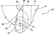
图5是安装在钻头面上并且在切削地层的过程中的、根据本发明的一个实施方式的PDC切削元件的侧视图。5 is a side view of a PDC cutting element according to one embodiment of the present invention installed on the bit face and in the process of cutting a formation.
具体实施方式Detailed ways
已经确认如下事实:平面状PDC切削元件的切削边缘或切削面周边的斜切或斜角事实上确实减小了(如果不是阻止的话)边缘碎裂和由于断裂导致的故障。已经发现倒圆的切削边缘也大大增强了切削边缘的抗碎裂性。但是,测试已经确认,从对切削元件的金刚石台的边缘进行斜切或倒圆获得的好处的程度极大地取决于斜切面或半径的尺寸。在测量斜切面时,获取垂直地或者在深度方向上从切削面的正面到斜切面结束的部位的尺寸。对于倒圆的边缘,基准尺寸是倒圆边缘的曲率半径。为了提供最大的有利的抗碎裂效果,已经确认金刚石台的边缘上的斜切部或半径必须相对大——0.040-0.045英寸(0.1016cm-0.1143cm)的级别。但是这种大的斜切面显著降低了切削效率。更小的斜切面和边缘半径——0.015-0.020英寸(0.0381cm-0.0508cm)的级别——相比于更大尺寸的斜切面和半径在提供抗断裂方面不太有效,但是确实提供了更好的切削效率。锐利边缘的切削元件提供了最大的切削效率但是极易碎,并且仅可以用在挑战最小的钻进应用中。较小斜切和倒圆边缘的切削元件的该缺点在重复冲击下尤其明显,比如切削元件在实际的钻进操作中遭受的那些重复冲击。The fact that chamfering or beveling of the cutting edge or cutting face perimeter of planar PDC cutting elements does in fact reduce, if not prevent, edge chipping and failure due to breakage has been confirmed. It has been found that the rounded cutting edge also greatly enhances the chipping resistance of the cutting edge. However, testing has confirmed that the degree of benefit gained from chamfering or rounding the edges of the diamond table of the cutting element depends greatly on the size of the chamfer or radius. When measuring the chamfer, the dimension is taken vertically or in the depth direction from the front face of the chamfer to the point where the chamfer ends. For rounded edges, the base dimension is the radius of curvature of the rounded edge. In order to provide the greatest beneficial anti-fragmentation effect, it has been determined that the chamfers or radii on the edges of the diamond table must be relatively large - on the order of 0.040-0.045 inches (0.1016cm-0.1143cm). But this large chamfer significantly reduces cutting efficiency. Smaller bevels and edge radii—on the order of 0.015-0.020 inches (0.0381cm-0.0508cm)—are less effective at providing fracture resistance than larger bevels and radii, but do provide more Good cutting efficiency. Sharp-edged cutting elements provide maximum cutting efficiency but are extremely brittle and should only be used in the least challenging drilling applications. This disadvantage of less chamfered and rounded edge cutting elements is especially pronounced under repeated impacts, such as those to which cutting elements are subjected during actual drilling operations.
斜切面和半径的抗碎裂特性和切削效率的尺寸相关性已经为斜切面的设计提供了微妙的选择,以找出适合于每个应用的最佳方案。因为单个钻头一般跨越多个地层延伸,所以对于耐用性的需求通常导致实际中的妥协,这导致在大部分操作时间的切削效率都极其不佳。需要更结实的边缘抛光技术来提供改进的切削效率而不丧失碎裂和断裂形式的切削元件耐用性。虽然前面提到的三斜切面方案提供了一些这样的效果,同时双斜切面方案(在这两个斜切面之间设置弓形表面)也似乎是有前景的,但是本发明人这里已经发现,在具有切削面的内边界处具有显著大的半径或弓形表面、并且在具有侧表面的外边界处具有锐利过渡部的斜切面提供了相较于前述切削边缘几何形状的显著的优点。The chipping resistance properties of the chamfer and radius and the dimensional dependence of cutting efficiency have provided delicate choices in the design of the chamfer to find the best solution for each application. Because a single drill bit typically extends across multiple formations, the need for durability often results in practical compromises that result in extremely poor cutting efficiency for most of the operating time. There is a need for stronger edge finishing techniques to provide improved cutting efficiency without loss of cutting element durability in the form of chipping and fracture. While the previously mentioned three-chamfer scheme provides some of these effects, while the double-chamfer scheme (with an arcuate surface between the two chamfer planes) also seems promising, the inventors have found here that in A chamfer with a substantially larger radius or arcuate surface at the inner boundary of the cutting face and a sharp transition at the outer boundary with side surfaces offers significant advantages over the aforementioned cutting edge geometries.
参见附图中的图1至图3和图5,根据本发明的PDC切削元件10包括基本是平面的金刚石或其他超硬磨料台12,其与之前描述的那种碳化钨基底14可以是层叠的或者不是层叠的。正如这里使用的,术语“基本是平面的”意思是并且包括具有在两个方向上延伸的切削面的台,该台具有显著大于深度的宽度。所述切削面不需要是平面的,所述台12与基底14之间的界面同样也不需要是平面的——这样的界面通常根据本领域的现有技术是非平面的。金刚石台12可以具有如图所示的圆形结构,也可以是半圆形或墓碑的形状,包括较大的非对称的金刚石台——其由较小的元件或者经由金刚石薄膜技术形成,或者包括本领域或其他领域中公知的其他结构。金刚石台12的外周面16(“外”表示当钻头在钻进操作中在WOB作用下转动时切削元件的接合地层38(图5)的边缘)是弓形表面/斜切面结构的组合,包括斜切表面20和在斜切表面20和金刚石台12的切削面24的内边界处的相邻的弓形表面22以及在斜切表面20和金刚石台12的侧表面28的外边界处的锐角过渡部26。如果使用基底14,那金刚石台12的侧表面28通常与基底14的侧面18连续,该侧面18通常与金刚石台12的平面垂直。在一些实施方式中,基底的侧表面18在其与金刚石台12的交界附近可以相对于PDC切削元件10的纵轴L以锐角定位,其中金刚石台12的侧表面28以相同的角度与其连续。Referring to Figures 1 through 3 and 5 of the drawings, a
在图1到3的实施方式中,斜切表面20相对于金刚石台侧表面28的取向以锐角延伸,其(在传统的PDC切削元件中)通常垂直于金刚石台12或者与金刚石台12的平面呈90°。斜切表面20可以相对于金刚石台12的侧表面28以大约15°到大约70°之间的角度α布置,如图1和2中所示,所述侧表面28平行于切削元件的纵轴L。但是,本发明并不局限于上述角度,应该指出的是,相互不垂直的金刚石台面和侧面的使用(比如在具有凹入或其他凸出的面结构或者相对于纵轴L以一角度取向的侧面的切削元件的情况下)在必要时可以改变相应的角度α的大小。In the embodiment of FIGS. 1 to 3 , the chamfered
另一种体现本发明特征的方式可以是关于斜切表面20与切削面24之间的夹角,其中根据本发明,斜切表面20与切削面24之间的夹角δ大于大约135°。Another way of embodying the features of the present invention may be with respect to the angle between the
可以(如图3中所示)但并非必要地包括曲率半径的弓形表面22符合期望地延伸到与斜切表面20和切削面24的相应的接触点C1和C2。虽然可能不需要精确的相切关系,但是斜切表面20和切削面24分别尽可能地在各自的接触点C1和C2处与弓形表面22的弯曲形状相切是理想的。进一步理想的是斜切表面20和切削面24的至少一个相切地接触弓形表面22。因此,正如在图3中的横截面中尤其明显地示出的,斜切面20和切削面24基本是直线的,而其间布置的表面22是弓形的并且(通过示例的方式)包括曲率半径R(图3),斜切表面20和切削面24在相应的接触点C1和C2处与所述表面22相切。应该指出的是,弓形表面22正如在图3中以阴影线示出的,其与斜切表面20和切削面24具有模糊的相应的边界,因为在实际中,弓形表面22与侧表面20和24的每个之间的精确的相切接触将不呈现出任何明显的边界,基本相切的接触在许多情况下将导致同样模糊的边界。The
据信在传统的切削元件金刚石台的锐角周边处的应力集中至少某种程度上导致碎裂和层裂。虽然金刚石台边缘的倒圆消除了锐角边缘,但正如之前指出的,为了有效地抗碎裂、层裂和断裂的大半径以不可接受的成本实现,并且将切削边缘的侵略性降到不可接受的程度。图1-3中示出的布置在切削面与斜切面之间的弓形表面据信对冲击引起的破坏呈现出与上述“大半径”方法相同的抵抗力,将金刚石台边缘应力集中显著地降低到某一阈值水平以下,同时金刚石台的斜切面与侧表面之间的锐利角过渡部提供了有效的切削动作。It is believed that stress concentrations at the sharp perimeter of the diamond table of conventional cutting elements lead to chipping and spalling, at least to some extent. While the rounding of the diamond table edge eliminates sharp edges, as previously pointed out, large radii to effectively resist chipping, spalling and fracture are achieved at unacceptable cost and reduce the aggressiveness of the cutting edge to unacceptable Degree. The arcuate surfaces shown in Figures 1-3 disposed between the cutting face and the chamfer face are believed to exhibit the same resistance to impact induced failure as the "large radius" approach described above, significantly reducing stress concentrations at the diamond table edge Below a certain threshold level, at the same time, the sharp angular transition between the chamfer and side surfaces of the diamond table provides efficient cutting action.
图4示出了本发明的PDC切削元件10′的另一个实施方式,其中之前结合图1到3描述的元件由类似的附图标记表示。参见图1,2,4和5,PDC切削元件10′包括基本是平面的金刚石或其他超硬磨料台,其可以与之前描述的那种碳化钨基底14层叠或者不层叠。切削面不需要是平面的,所述台12与基底14之间的界面也不必一定要是平面的——这种界面根据本领域的现有技术通常是非平面的。金刚石台12可以具有如图所示的圆形结构,或者可以是半圆形或墓碑形状,包括较大的非对称金刚石台,其由较小的元件构成或者经由金刚石薄膜技术构成,或者包括本领域或其他领域中已知的其他结构。金刚石台12的外周面16(“外”表示当钻头在钻进操作中在WOB作用下转动时切削元件的接合地层38(图5)的边缘)是弓形表面/斜切面结构的组合,包括:径向外斜切表面20、径向内斜切表面20′和在径向内斜切表面20′的与金刚石台12的切削面24的内边界处的相邻的弓形表面22、以及在径向外斜切表面20的与金刚石台12的侧表面28的外边界处的锐利角过渡部26。如果使用基底14,那金刚石台12的侧表面28通常与基底14的侧面18连续,该侧面18通常与金刚石台12的平面垂直。在一些实施方式中,基底的侧表面18在其与金刚石台12的交界附近可以相对于PDC切削元件10的纵轴L以锐角定位,其中金刚石台12的侧表面28以相同的角度与其连续。Fig. 4 shows another embodiment of a PDC cutting element 10' of the present invention, wherein elements previously described in connection with Figs. 1 to 3 are indicated by like reference numerals. Referring to Figures 1, 2, 4 and 5, a PDC cutting element 10' includes a substantially planar diamond or other superabrasive table, which may or may not be laminated to a
在图1,2和4的实施方式中,斜切表面20相对于金刚石台侧表面28的取向以锐角延伸,其(在传统的PDC切削元件中)通常垂直于金刚石台12的平面或者与金刚石台12的平面呈90°。斜切表面20可以相对于金刚石台12的侧表面28以大约15°到大约70°之间的角度α布置,如图1和2中所示,所述侧表面28平行于切削元件的纵轴L。径向内斜切表面20′可以相对于金刚石台12的侧表面28以一角度β布置,相对于侧表面28的角度β大于α(β>α)。但是,本发明并不局限于上述角度,应该指出的是,相互不垂直的金刚石台面和侧面的使用(比如在具有凹入或其他凸出的面结构或者相对于纵轴L以一角度取向的侧面的切削元件的情况下)在必要时可以改变相应的角度α的大小。In the embodiment of Figures 1, 2 and 4, the chamfered
另一种体现本发明特征的方式可以是关于径向外斜切表面20与切削面24之间的夹角,其中根据本发明,径向外斜切表面20与切削面24之间的夹角δ大于大约135°。Another way of embodying the features of the present invention may be with respect to the angle between the radially outer
可以(如图4中所示)但并非一定要包括曲率半径的弓形表面22符合期望地延伸到与径向内斜切表面20′和切削面24的相应的接触点C1和C2。虽然可能不需要精确的相切关系,但是径向内斜切表面20′和切削面24分别尽可能地在各自的接触点C1和C2处与弓形表面22的弯曲形状相切是理想的。进一步理想的是径向内斜切表面20′和切削面24中的至少一个相切地接触弓形表面22。因此,正如在图4中的横截面中尤其明显地示出的,径向内斜切面20′和切削面24基本是直线的,而其间布置的表面22是弓形的并且(通过示例的方式)包括曲率半径R(图3),径向内斜切表面20′和切削面24在相应的接触点C1和C2处与所述表面22相切。应该指出的是,弓形表面22正如在图4中以阴影线示出的,其与径向内斜切表面20′和切削面24具有模糊的相应的边界,因为在实际中,弓形表面22与侧表面20′和24的每个之间的精确的相切接触将不表现出任何明显的边界,基本相切的接触在许多情况下将导致同样模糊的边界。
布置在图1,2和4中示出的切削面与斜切面之间的弓形表面据信对冲击引起的破坏呈现出与之前提到的大半径方法相同的抵抗力,将金刚石台边缘应力集中显著地降低到某阈值水平以下,同时金刚石台的斜切面与侧表面之间的锐利角过渡部提供了有效的切削动作。The arcuate surfaces disposed between the cutting and chamfer faces shown in Figures 1, 2 and 4 are believed to exhibit the same resistance to impact-induced failure as the previously mentioned large radius approach, concentrating stress at the diamond table edge Significantly below a certain threshold level, while the sharp angular transition between the chamfer and side surfaces of the diamond table provides efficient cutting action.
图5示出了安装在旋转刮刀钻头34的钻头面32的凸出部30上的根据本发明的PDC切削元件10,10′。将刮刀钻头34布置在井孔中,以便于当钻头34转动并且将钻压施加到钻头34固定于其上的钻柱上时,PDC切削元件10,10′的金刚石台12的周边16接合地层36。将会看出,法向力N基本平行于钻头轴线取向,具有后倾角的PDC切削元件10,10′以一锐角承受所述法向力N。在图4的说明中,PDC切削元件10,10′以15°的后倾角γ取向——如果PDC切削元件10,10′是传统的锐利边缘设计,则其将施加到金刚石台的前面与侧面之间的“拐角”上,并且由于由该点提供的最小的支承面积或者金刚石台边缘的线接触而导致极其高的、破坏性的力集中。但是,应用在图5的钻头上的PDC切削元件10可以包括相对于侧表面28(例如)15°到20°的斜切角α,这基本与切削元件的后倾角γ相同或者稍大。在这种布置的情况下,弓形表面22承受并分配由法向力N引起的加载在PDC切削元件上的大部分载荷,并且减小钻进期间在切削面24上被向上推的地层切屑的应力。此外,金刚石台12的斜切表面20与侧表面28之间的锐利角过渡部26提供了具有侵略性的、有效的切削边缘以用于移除地层材料。换言之,由于弓形表面22的存在,相比于具有传统的90°切削边缘的切削元件的点或线接触,每单位面积的负载显著降低,在钻进较硬地层时尤其有利,不会牺牲钻进效率。此外,斜切表面20有效地增大了由地层“看到”的金刚石台12的表面以及垂直于该表面施加的法向力N,而锐利角过渡部26提供了理想地具有侵略性的切削边缘。FIG. 5 shows a
通过利用“有效”后倾角(其考虑了切削元件在钻头上的径向位置以及设计速率或者穿透速率的设计范围,以将钻头的每英尺前进中由切削元件移动的实际距离的因素考虑在内,从而获得操作中切削元件的真实的或有效的后倾角),可以获得更为复杂的协调切削元件后倾角和斜切角的方法。利用当前计算机中可用的计算能力,这种练习是相对容易的,但是事实上是不必要的,只要在钻头中使用的斜切面与使用嵌钉式切削元件的固定钻头的明显的后倾角匹配即可。但是,在切削元件凹窝是在基体式钻头中铸造出来的情形,这种各后倾角计算以及每个切削元件上匹配的斜切角的研磨可以作为正常制造工艺的一部分。By utilizing an "effective" back rake (which takes into account the radial position of the cutting elements on the bit and the design range of the design rate or penetration rate) to factor in the actual distance moved by the cutting elements per foot of drill bit advancement In order to obtain the true or effective back rake angle of the cutting element in operation), a more complex method of coordinating the back rake and bevel angle of the cutting element can be obtained. With the computing power available in current computers, this exercise is relatively easy, but in fact unnecessary, as long as the chamfer used in the drill matches the apparent back rake of a fixed drill using studded cutting elements. Can. However, where the cutting element pockets are cast in the matrix drill bit, this back rake calculation and grinding of matching chamfer angles on each cutting element can be done as part of the normal manufacturing process.
根据本发明的PDC切削元件(包括TSP)的制作可以通过使用金刚石磨料或放电砂轮或者它们的组合以及上面安装切削元件的合适的固定装置(在圆形或部分圆形元件的情况下,使它们旋转经过砂轮)的使用而容易地实现。PDC cutting elements (including TSP) according to the present invention can be produced by using diamond abrasives or electrical discharge grinding wheels or a combination thereof and suitable fixtures on which the cutting elements are mounted (in the case of round or partially round elements, making them Rotation is easily achieved through the use of grinding wheels).
虽然已经结合基本是平面的金刚石台对本发明进行了描述,但是应该意识到的是,术语“基本是平面”预见到并包括凸起的、凹入的和其他非直线的金刚石台——不过它们都包括横向尺寸大于其深度的二维金刚石层,其可以具有接近外周边缘的切削边缘。此外,本发明适用于除了PDC结构之外的金刚石台,比如金刚石或类金刚石膜以及其他超硬磨料,比如立方氮化硼和氮化硅。Although the invention has been described in connection with a substantially planar diamond table, it should be appreciated that the term "substantially planar" foresees and includes convex, concave and other non-rectilinear diamond tables - however they Both include a two-dimensional diamond layer with a lateral dimension greater than its depth, which may have a cutting edge close to the peripheral edge. Furthermore, the invention is applicable to diamond tables other than PDC structures, such as diamond or diamond-like films and other superabrasives, such as cubic boron nitride and silicon nitride.
此外,必须理解的是,对于直的或线性的切削边缘以及比如这里图示并描述的弓形边缘,本发明具有同样的优点。虽然图示出的实施方式包括环形斜切面和布置在它们之间的环形的弓形表面,但是本发明并不局限于此。此外,可以预见到,仅金刚石台的一部分周边,例如一半或者甚至三分之一周边,可以根据本发明配置。Furthermore, it must be understood that the present invention has the same advantages for straight or linear cutting edges as well as for arcuate edges such as illustrated and described herein. While the illustrated embodiment includes annular chamfers and annular arcuate surfaces disposed therebetween, the invention is not so limited. Furthermore, it is envisioned that only a portion of the perimeter of the diamond table, such as half or even a third of the perimeter, may be configured in accordance with the invention.
最后,应该意识到并认可的是,当钻头在地层中推进时,弓形表面以及锐利角过渡部将被从金刚石台上磨掉,在切削元件上形成了基本是直线的“磨损平坦部”。但是,本发明的上面描述的特征用于在促进切削动作的同时增强对新的未使用的金刚石台的保护来抵抗冲击破坏直到金刚石台基本被磨损掉而不能切削地层,该点之后已被证明:金刚石台碎裂和层裂的趋势显著减小。Finally, it should be appreciated and appreciated that as the drill bit advances through the formation, arcuate surfaces and sharp corner transitions will be ground away from the diamond table, forming substantially straight "wear flats" on the cutting elements. However, the above described features of the present invention serve to enhance the protection of a new unused diamond table against impact damage while facilitating the cutting action until the diamond table is substantially worn away from cutting the formation, after which point it has been demonstrated : Significantly reduced tendency for diamond table chipping and spallation.
此外,虽然本发明已经结合旋转刮刀钻头进行了描述,但是术语“钻头”旨在不仅包括全面钻头,而且包括取心钻头以及其他转动钻进结构,包括不构成限定的偏心钻头、双心钻头、扩眼装置(包括不构成限定的所谓的“扩眼翼”)、牙轮或三牙轮钻头以及所谓的“混合式”钻头(即具有固定切削元件又具有转动切削元件),它们具有安装于其上的根据本发明的一个或多个切削元件。因此,这里术语“钻头”的使用以及对权利要求的特殊参考都预见到并包括之前所有的内容,以及额外类型的旋转钻进结构。Furthermore, while the invention has been described in connection with rotary drag bits, the term "drill" is intended to include not only full-face drills, but also core bits and other rotary drilling structures, including without limitation eccentric bits, double-centered bits, Reaming devices (including without limitation so-called "reaming wings"), roller cone or tri-cone bits, and so-called "hybrid" bits (that is, having both fixed and rotating cutting elements) that have One or more cutting elements according to the present invention thereon. Accordingly, use of the term "drill bit" herein and specific references to the claims anticipate and include all of the foregoing, as well as additional types of rotary drilling structures.
虽然这里已经结合某些实施方式披露了单独的或者结合有在钻头上特殊的协同安装取向的切削元件,但是本发明并不局限于此。本领普通技术人员将会意识到的是在不脱离权利要求的范围的前提下可以对本发明做出许多添加、删除和修改,包括合法的等价方式。Although cutting elements have been disclosed herein in connection with certain embodiments, either alone or in combination with specific cooperating mounting orientations on the drill bit, the invention is not limited thereto. Those of ordinary skill in the art will recognize that many additions, deletions and modifications can be made to the present invention, including legal equivalents, without departing from the scope of the claims.
Claims (15)
Applications Claiming Priority (3)
| Application Number | Priority Date | Filing Date | Title |
|---|---|---|---|
| US35350710P | 2010-06-10 | 2010-06-10 | |
| US61/353,507 | 2010-06-10 | ||
| PCT/US2011/038204WO2011156150A2 (en) | 2010-06-10 | 2011-05-26 | Superabrasive cutting elements with cutting edge geometry having enhanced durability and cutting effieciency and drill bits so equipped |
Publications (1)
| Publication Number | Publication Date |
|---|---|
| CN103025460Atrue CN103025460A (en) | 2013-04-03 |
Family
ID=45095320
Family Applications (1)
| Application Number | Title | Priority Date | Filing Date |
|---|---|---|---|
| CN2011800357831APendingCN103025460A (en) | 2010-06-10 | 2011-05-26 | Superabrasive cutting element with cutting edge geometry for enhanced durability and cutting efficiency and drill bit so equipped |
Country Status (10)
| Country | Link |
|---|---|
| US (1) | US9371700B2 (en) |
| EP (1) | EP2580012A2 (en) |
| CN (1) | CN103025460A (en) |
| BR (1) | BR112012031456A2 (en) |
| CA (1) | CA2801756A1 (en) |
| MX (1) | MX2012014405A (en) |
| RU (1) | RU2013100147A (en) |
| SA (1) | SA111320515B1 (en) |
| WO (1) | WO2011156150A2 (en) |
| ZA (1) | ZA201209555B (en) |
Cited By (1)
| Publication number | Priority date | Publication date | Assignee | Title |
|---|---|---|---|---|
| CN110770410A (en)* | 2017-05-02 | 2020-02-07 | 通用电气(Ge)贝克休斯有限责任公司 | Cutting elements configured to reduce impact damage and related tools and methods |
Families Citing this family (10)
| Publication number | Priority date | Publication date | Assignee | Title |
|---|---|---|---|---|
| US7036611B2 (en) | 2002-07-30 | 2006-05-02 | Baker Hughes Incorporated | Expandable reamer apparatus for enlarging boreholes while drilling and methods of use |
| US9243452B2 (en) | 2011-04-22 | 2016-01-26 | Baker Hughes Incorporated | Cutting elements for earth-boring tools, earth-boring tools including such cutting elements, and related methods |
| US8991525B2 (en) | 2012-05-01 | 2015-03-31 | Baker Hughes Incorporated | Earth-boring tools having cutting elements with cutting faces exhibiting multiple coefficients of friction, and related methods |
| US9482057B2 (en) | 2011-09-16 | 2016-11-01 | Baker Hughes Incorporated | Cutting elements for earth-boring tools, earth-boring tools including such cutting elements and related methods |
| US9428966B2 (en) | 2012-05-01 | 2016-08-30 | Baker Hughes Incorporated | Cutting elements for earth-boring tools, earth-boring tools including such cutting elements, and related methods |
| US9650837B2 (en) | 2011-04-22 | 2017-05-16 | Baker Hughes Incorporated | Multi-chamfer cutting elements having a shaped cutting face and earth-boring tools including such cutting elements |
| US9493991B2 (en) | 2012-04-02 | 2016-11-15 | Baker Hughes Incorporated | Cutting structures, tools for use in subterranean boreholes including cutting structures and related methods |
| US20150047910A1 (en)* | 2013-08-14 | 2015-02-19 | Smith International, Inc. | Downhole cutting tools having rolling cutters with non-planar cutting surfaces |
| US10307891B2 (en)* | 2015-08-12 | 2019-06-04 | Us Synthetic Corporation | Attack inserts with differing surface finishes, assemblies, systems including same, and related methods |
| US11828109B2 (en)* | 2021-06-07 | 2023-11-28 | Baker Hughes Oilfield Operations Llc | Cutting elements for earth-boring tools and related earth-boring tools and methods |
Citations (4)
| Publication number | Priority date | Publication date | Assignee | Title |
|---|---|---|---|---|
| US5653300A (en)* | 1993-11-22 | 1997-08-05 | Baker Hughes Incorporated | Modified superhard cutting elements having reduced surface roughness method of modifying, drill bits equipped with such cutting elements, and methods of drilling therewith |
| JP2004291204A (en)* | 2003-03-28 | 2004-10-21 | Tungaloy Corp | Cbn based sintered body cutting tool and its manufacturing method |
| US20070079991A1 (en)* | 2005-10-11 | 2007-04-12 | Us Synthetic Corporation | Cutting element apparatuses, drill bits including same, methods of cutting, and methods of rotating a cutting element |
| US7475744B2 (en)* | 2005-01-17 | 2009-01-13 | Us Synthetic Corporation | Superabrasive inserts including an arcuate peripheral surface |
Family Cites Families (18)
| Publication number | Priority date | Publication date | Assignee | Title |
|---|---|---|---|---|
| US4109737A (en) | 1976-06-24 | 1978-08-29 | General Electric Company | Rotary drill bit |
| USRE32036E (en) | 1980-06-11 | 1985-11-26 | Strata Bit Corporation | Drill bit |
| GB8616926D0 (en) | 1986-07-11 | 1986-08-20 | Dzus Fastener Europe | Trunking fastener |
| DE68905106T2 (en) | 1988-06-28 | 1993-09-02 | Camco Drilling Group Ltd | CUTTING ELEMENTS FOR ROTARY DRILL CHISELS. |
| US4858707A (en) | 1988-07-19 | 1989-08-22 | Smith International, Inc. | Convex shaped diamond cutting elements |
| NO169735C (en) | 1989-01-26 | 1992-07-29 | Geir Tandberg | COMBINATION DRILL KRONE |
| US5437343A (en) | 1992-06-05 | 1995-08-01 | Baker Hughes Incorporated | Diamond cutters having modified cutting edge geometry and drill bit mounting arrangement therefor |
| US6330924B1 (en)* | 1996-09-25 | 2001-12-18 | David R. Hall | Superhard drill bit heel, gage, and cutting elements with reinforced periphery |
| US5881830A (en) | 1997-02-14 | 1999-03-16 | Baker Hughes Incorporated | Superabrasive drill bit cutting element with buttress-supported planar chamfer |
| US6006846A (en) | 1997-09-19 | 1999-12-28 | Baker Hughes Incorporated | Cutting element, drill bit, system and method for drilling soft plastic formations |
| US6527069B1 (en) | 1998-06-25 | 2003-03-04 | Baker Hughes Incorporated | Superabrasive cutter having optimized table thickness and arcuate table-to-substrate interfaces |
| US6935444B2 (en) | 2003-02-24 | 2005-08-30 | Baker Hughes Incorporated | Superabrasive cutting elements with cutting edge geometry having enhanced durability, method of producing same, and drill bits so equipped |
| US7681669B2 (en) | 2005-01-17 | 2010-03-23 | Us Synthetic Corporation | Polycrystalline diamond insert, drill bit including same, and method of operation |
| JP4728256B2 (en) | 2005-10-06 | 2011-07-20 | 住友電工ハードメタル株式会社 | Cutting tool for high-quality and high-efficiency machining and cutting method using the same |
| US8080074B2 (en) | 2006-11-20 | 2011-12-20 | Us Synthetic Corporation | Polycrystalline diamond compacts, and related methods and applications |
| WO2008076420A1 (en) | 2006-12-18 | 2008-06-26 | Baker Hughes Incorporated | Superabrasive cutting elements with enhanced durability and increased wear life, and drilling apparatus so equipped |
| US8061456B2 (en)* | 2007-08-27 | 2011-11-22 | Baker Hughes Incorporated | Chamfered edge gage cutters and drill bits so equipped |
| US8887839B2 (en)* | 2009-06-25 | 2014-11-18 | Baker Hughes Incorporated | Drill bit for use in drilling subterranean formations |
- 2011
- 2011-05-26MXMX2012014405Apatent/MX2012014405A/ennot_activeApplication Discontinuation
- 2011-05-26USUS13/116,936patent/US9371700B2/enactiveActive
- 2011-05-26EPEP11792885.3Apatent/EP2580012A2/ennot_activeWithdrawn
- 2011-05-26WOPCT/US2011/038204patent/WO2011156150A2/enactiveApplication Filing
- 2011-05-26RURU2013100147/02Apatent/RU2013100147A/ennot_activeApplication Discontinuation
- 2011-05-26CACA2801756Apatent/CA2801756A1/ennot_activeAbandoned
- 2011-05-26BRBR112012031456Apatent/BR112012031456A2/ennot_activeIP Right Cessation
- 2011-05-26CNCN2011800357831Apatent/CN103025460A/enactivePending
- 2011-06-07SASA111320515Apatent/SA111320515B1/enunknown
- 2012
- 2012-12-14ZAZA2012/09555Apatent/ZA201209555B/enunknown
Patent Citations (4)
| Publication number | Priority date | Publication date | Assignee | Title |
|---|---|---|---|---|
| US5653300A (en)* | 1993-11-22 | 1997-08-05 | Baker Hughes Incorporated | Modified superhard cutting elements having reduced surface roughness method of modifying, drill bits equipped with such cutting elements, and methods of drilling therewith |
| JP2004291204A (en)* | 2003-03-28 | 2004-10-21 | Tungaloy Corp | Cbn based sintered body cutting tool and its manufacturing method |
| US7475744B2 (en)* | 2005-01-17 | 2009-01-13 | Us Synthetic Corporation | Superabrasive inserts including an arcuate peripheral surface |
| US20070079991A1 (en)* | 2005-10-11 | 2007-04-12 | Us Synthetic Corporation | Cutting element apparatuses, drill bits including same, methods of cutting, and methods of rotating a cutting element |
Cited By (2)
| Publication number | Priority date | Publication date | Assignee | Title |
|---|---|---|---|---|
| CN110770410A (en)* | 2017-05-02 | 2020-02-07 | 通用电气(Ge)贝克休斯有限责任公司 | Cutting elements configured to reduce impact damage and related tools and methods |
| CN110770410B (en)* | 2017-05-02 | 2021-06-01 | 通用电气(Ge)贝克休斯有限责任公司 | Cutting elements configured to reduce impact damage and related tools and methods |
Also Published As
| Publication number | Publication date |
|---|---|
| WO2011156150A2 (en) | 2011-12-15 |
| SA111320515B1 (en) | 2014-08-31 |
| BR112012031456A2 (en) | 2016-11-08 |
| US9371700B2 (en) | 2016-06-21 |
| CA2801756A1 (en) | 2011-12-15 |
| EP2580012A2 (en) | 2013-04-17 |
| WO2011156150A3 (en) | 2012-04-05 |
| RU2013100147A (en) | 2014-07-20 |
| US20110303466A1 (en) | 2011-12-15 |
| ZA201209555B (en) | 2014-03-26 |
| MX2012014405A (en) | 2013-02-15 |
Similar Documents
| Publication | Publication Date | Title |
|---|---|---|
| US10914124B2 (en) | Cutting elements comprising waveforms and related tools and methods | |
| CN103025460A (en) | Superabrasive cutting element with cutting edge geometry for enhanced durability and cutting efficiency and drill bit so equipped | |
| US10851594B2 (en) | Kerfing hybrid drill bit and other downhole cutting tools | |
| EP3191677B1 (en) | Multi-chamfer cutting elements having a shaped cutting face, earth-boring tools including such cutting elements. | |
| US6935444B2 (en) | Superabrasive cutting elements with cutting edge geometry having enhanced durability, method of producing same, and drill bits so equipped | |
| US9458674B2 (en) | Earth-boring tools including shaped cutting elements, and related methods | |
| US8684112B2 (en) | Cutting elements for earth-boring tools, earth-boring tools including such cutting elements and related methods | |
| US9797200B2 (en) | Methods of fabricating cutting elements for earth-boring tools and methods of selectively removing a portion of a cutting element of an earth-boring tool | |
| EP3268571B1 (en) | Cutting elements configured to mitigate diamond table failure, earth-boring tools including such cutting elements, and related methods | |
| US12134938B2 (en) | Cutting elements for earth-boring tools, methods of manufacturing earth-boring tools, and related earth-boring tools | |
| CN112437827A (en) | Cutting elements configured to reduce impact damage and related tools and methods-alternative configurations | |
| US12320199B1 (en) | Cutting elements and geometries for reduced vibrations, earth-boring tools, and related methods | |
| US11920409B2 (en) | Cutting elements, earth-boring tools including the cutting elements, and methods of forming the earth-boring tools |
Legal Events
| Date | Code | Title | Description |
|---|---|---|---|
| C06 | Publication | ||
| PB01 | Publication | ||
| C10 | Entry into substantive examination | ||
| SE01 | Entry into force of request for substantive examination | ||
| C02 | Deemed withdrawal of patent application after publication (patent law 2001) | ||
| WD01 | Invention patent application deemed withdrawn after publication | Application publication date:20130403 |