CN103025404A - Modular filter elements for use in a filter-in-filter cartridge - Google Patents
Modular filter elements for use in a filter-in-filter cartridgeDownload PDFInfo
- Publication number
- CN103025404A CN103025404ACN2011800303530ACN201180030353ACN103025404ACN 103025404 ACN103025404 ACN 103025404ACN 2011800303530 ACN2011800303530 ACN 2011800303530ACN 201180030353 ACN201180030353 ACN 201180030353ACN 103025404 ACN103025404 ACN 103025404A
- Authority
- CN
- China
- Prior art keywords
- cartridge
- filter
- layer
- media
- filter material
- Prior art date
- Legal status (The legal status is an assumption and is not a legal conclusion. Google has not performed a legal analysis and makes no representation as to the accuracy of the status listed.)
- Granted
Links
Images


Classifications
- B—PERFORMING OPERATIONS; TRANSPORTING
- B01—PHYSICAL OR CHEMICAL PROCESSES OR APPARATUS IN GENERAL
- B01D—SEPARATION
- B01D29/00—Filters with filtering elements stationary during filtration, e.g. pressure or suction filters, not covered by groups B01D24/00 - B01D27/00; Filtering elements therefor
- B01D29/01—Filters with filtering elements stationary during filtration, e.g. pressure or suction filters, not covered by groups B01D24/00 - B01D27/00; Filtering elements therefor with flat filtering elements
- B01D29/05—Filters with filtering elements stationary during filtration, e.g. pressure or suction filters, not covered by groups B01D24/00 - B01D27/00; Filtering elements therefor with flat filtering elements supported
- B01D29/07—Filters with filtering elements stationary during filtration, e.g. pressure or suction filters, not covered by groups B01D24/00 - B01D27/00; Filtering elements therefor with flat filtering elements supported with corrugated, folded or wound filtering sheets
- B—PERFORMING OPERATIONS; TRANSPORTING
- B01—PHYSICAL OR CHEMICAL PROCESSES OR APPARATUS IN GENERAL
- B01D—SEPARATION
- B01D29/00—Filters with filtering elements stationary during filtration, e.g. pressure or suction filters, not covered by groups B01D24/00 - B01D27/00; Filtering elements therefor
- B01D29/11—Filters with filtering elements stationary during filtration, e.g. pressure or suction filters, not covered by groups B01D24/00 - B01D27/00; Filtering elements therefor with bag, cage, hose, tube, sleeve or like filtering elements
- B01D29/13—Supported filter elements
- B01D29/15—Supported filter elements arranged for inward flow filtration
- B01D29/21—Supported filter elements arranged for inward flow filtration with corrugated, folded or wound sheets
- B—PERFORMING OPERATIONS; TRANSPORTING
- B01—PHYSICAL OR CHEMICAL PROCESSES OR APPARATUS IN GENERAL
- B01D—SEPARATION
- B01D29/00—Filters with filtering elements stationary during filtration, e.g. pressure or suction filters, not covered by groups B01D24/00 - B01D27/00; Filtering elements therefor
- B01D29/50—Filters with filtering elements stationary during filtration, e.g. pressure or suction filters, not covered by groups B01D24/00 - B01D27/00; Filtering elements therefor with multiple filtering elements, characterised by their mutual disposition
- B01D29/56—Filters with filtering elements stationary during filtration, e.g. pressure or suction filters, not covered by groups B01D24/00 - B01D27/00; Filtering elements therefor with multiple filtering elements, characterised by their mutual disposition in series connection
- B01D29/58—Filters with filtering elements stationary during filtration, e.g. pressure or suction filters, not covered by groups B01D24/00 - B01D27/00; Filtering elements therefor with multiple filtering elements, characterised by their mutual disposition in series connection arranged concentrically or coaxially
- B—PERFORMING OPERATIONS; TRANSPORTING
- B01—PHYSICAL OR CHEMICAL PROCESSES OR APPARATUS IN GENERAL
- B01D—SEPARATION
- B01D2201/00—Details relating to filtering apparatus
- B01D2201/12—Pleated filters
- B—PERFORMING OPERATIONS; TRANSPORTING
- B01—PHYSICAL OR CHEMICAL PROCESSES OR APPARATUS IN GENERAL
- B01D—SEPARATION
- B01D2201/00—Details relating to filtering apparatus
- B01D2201/29—Filter cartridge constructions
- B01D2201/291—End caps
- B01D2201/295—End caps with projections extending in a radial outward direction, e.g. for use as a guide, spacing means
Landscapes
- Chemical & Material Sciences (AREA)
- Chemical Kinetics & Catalysis (AREA)
- Filtering Materials (AREA)
- Filtration Of Liquid (AREA)
- Filtering Of Dispersed Particles In Gases (AREA)
- Separation Using Semi-Permeable Membranes (AREA)
Abstract
Translated fromChinese
Description
Translated fromChinese技术领域technical field
本发明的领域涉及过滤器,诸如用于燃料-水分离的滤中滤(filter-in-filter)的筒。特别地,该领域涉及优选地包括热塑性材料的滤中滤的燃料-水分离器以及粒子过滤器。The field of the invention relates to filters, such as filter-in-filter cartridges for fuel-water separation. In particular, the field relates to filter-in-filter fuel-water separators and particle filters, preferably comprising thermoplastic materials.
本申请的主题涉及2010年6月22日提交的名称为“用于在滤中滤的筒中使用的模块化过滤单元”的美国专利申请No.12/820,791以及2010年6月22日提交的名称为“两级水分离器和粒子过滤器”的美国专利申请No.12/820,784,本申请要求上述两个申请的优先权,它们的全部内容以引用的方式并入本文。The subject matter of this application is related to U.S. Patent Application No. 12/820,791, filed June 22, 2010, entitled "Modular Filtration Unit for Use in Filter-in-Filtration Cartridges," and filed June 22, 2010 to the title US Patent Application No. 12/820,784 for "Two-Stage Water Separator and Particle Filter," to which this application claims priority from both of the aforementioned applications, the entire contents of which are incorporated herein by reference.
背景技术Background technique
聚结器广泛地用于从气态或液态连续相中去除非混相液滴,诸如用在曲轴箱通风(CV)过滤、燃料水分离(FWS)和油-水分离中。现有技术的聚结器设计引入如下原理:通过利用分级捕获(即,减小聚结介质中的纤维直径、孔径和/或孔隙率)或通过利用大厚度的聚结器来增强液滴捕获和聚结。润湿性也被认识到影响聚结器性能。(见例如美国专利No.6,767,459以及美国专利申请公开No.2007-0131235和No.2007-0062887)。美国专利No.5,443,724公开了介质应当具有比水大的表面能,以提高聚结性能(即,介质应当优选地由聚结液滴和连续相两者润湿)。美国专利No.4,081,373公开了聚结介质应当疏水,以从燃料去除水。美国专利申请公开No.2006-0242933公开了一种油-雾聚结器,其中,过滤介质是疏油的,从而能够使流体雾聚结产液滴并且从过滤介质排出。Coalescers are widely used to remove immiscible droplets from gaseous or liquid continuous phases, such as in crankcase ventilation (CV) filtration, fuel water separation (FWS) and oil-water separation. Prior art coalescer designs incorporate the principle of enhancing droplet capture by utilizing graded capture (i.e., reducing fiber diameter, pore size, and/or porosity in the coalescing media) or by utilizing large thickness coalescers and coalesce. Wettability is also recognized to affect coalescer performance. (See, eg, US Patent No. 6,767,459 and US Patent Application Publication Nos. 2007-0131235 and 2007-0062887). US Patent No. 5,443,724 discloses that the media should have a surface energy greater than water to enhance coalescing performance (ie, the media should preferably be wetted by both the coalescing droplets and the continuous phase). US Patent No. 4,081,373 discloses that the coalescing media should be hydrophobic in order to remove water from the fuel. US Patent Application Publication No. 2006-0242933 discloses an oil-mist coalescer in which the filter media is oleophobic, thereby enabling the fluid mist to coalesce to produce liquid droplets and drain from the filter media.
关于从燃料去除水,需要增加移除效率并且去除比之前的小的液滴。由于引入具有低界面张力和不同添加剂组合的新燃料,与之前的燃料相比,该挑战被进一步放大。特别地,超低硫柴油(ULSD)燃料和生物柴油趋于具有更低的界面张力(IFT),因此,与之前的柴油燃料相比,具有较小的液滴尺寸和更稳定的乳状液。在具有低界面张力的燃料中,分散的液滴的尺寸减小,使液滴更难以去除。因此,需要增强聚结以满足这些挑战。考虑到改进聚结效率,还期望包括改进的聚结介质的改进的聚结器,因为其允许使用小的介质包。在具有低界面张力的燃料中,液滴的尺寸减小,使液滴更难以去除。Regarding the removal of water from fuel, there is a need to increase removal efficiency and remove smaller droplets than before. This challenge is further amplified by the introduction of new fuels with low interfacial tension and different additive combinations compared to previous fuels. In particular, ultra-low sulfur diesel (ULSD) fuels and biodiesel tend to have lower interfacial tension (IFT), and therefore, smaller droplet sizes and more stable emulsions than previous diesel fuels. In fuels with low interfacial tension, the dispersed droplets decrease in size, making them more difficult to remove. Therefore, enhanced coalescence is required to meet these challenges. In view of improving coalescing efficiency, an improved coalescer including improved coalescing media is also desired because it allows the use of small media packs. In fuels with low interfacial tension, the size of the droplets decreases, making them more difficult to remove.
传统的燃料-水分离器(FWS)趋于是设计成用于燃料泵的上游的单级装置。在传统的FWS中,过滤介质关于分散的水相是疏性的,并且用作阻碍部件。然而,对于具有低IFTs(<15达因/厘米)和低分离性(<50%)的ULSD燃料和生物柴油,传统的FWS趋于不能提供足够的水去除,这是因为它们的孔尺寸趋于太大而不能有效地捕获小液滴。因而,对于有效的捕获,需要大的液滴尺寸。当FWS用在燃料泵的上游时,维持跨越FWS的压降最好在一个大气压以下的需求,也需要这种大的液滴尺寸。另外,即使在平均孔径足够小的情况下,FWS介质和纤维过滤器介质通常具有的最大孔径太大而超过通过这些大孔的水的大小。在现今的高压共轨燃料系统中,从通过喷射器的燃料去除几乎所有的非溶解水是重要的,因此通过这就是说些大孔的水的量是不可接受的。另外,在现今的HPCR燃料系统中,经常希望燃料水分离器位于泵的压力侧,在该侧过滤器暴露于较高的压力,水滴的尺寸特别小。传统的二级燃料-水聚结器(FWC)被设计成用于燃料泵的下游,趋于是燃料用二级装置,其中,第一级捕获滴、保持该滴从而发生聚结,随后释放增大的滴落物,通过沉积/沉降、典型地在被第二分离器级(其中,第二分离器级用作FWS)阻挡之后去除增大的滴落物。传统的二级FWC趋于提供比FWS高的去除效率,但是归因于被固体或半固体堵塞而趋于具有不足够长度寿命。为了改变FWS和FWC两者受到表面张力降低、滴尺寸减小、聚结速度降低、乳状液稳定并且可能吸收到介质上使得效率变低的燃料中存在的表面活性剂的不利影响的程度。因而,需要展现出高效率、低压降并且受低界面张力和表面活性的存在影响小的改善的燃料-水分离器。Conventional fuel-water separators (FWS) tend to be single-stage devices designed upstream of the fuel pump. In conventional FWS, the filter media is hydrophobic with respect to the dispersed aqueous phase and acts as a barrier member. However, for ULSD fuels and biodiesel with low IFTs (<15 dyne/cm) and low separability (<50%), conventional FWS tend not to provide sufficient water removal because their pore size tends to too large to effectively capture small droplets. Thus, for efficient capture, large droplet sizes are required. This large droplet size is also required by the need to maintain the pressure drop across the FWS preferably below one atmosphere when the FWS is used upstream of a fuel pump. Additionally, even with sufficiently small average pore sizes, FWS media and fiber filter media often have a maximum pore size that is too large to pass the water through these large pores. In today's high pressure common rail fuel systems, it is important to remove nearly all of the non-dissolved water from the fuel passing through the injectors, so the amount of water passing through these large pores is unacceptable. Additionally, in today's HPCR fuel systems it is often desirable that the fuel water separator be located on the pressure side of the pump where the filter is exposed to higher pressures and the water droplet size is particularly small. Conventional two-stage fuel-water coalescers (FWCs), designed for use downstream of fuel pumps, tend to be two-stage devices for fuel, where the first stage captures droplets, holds them so coalescing occurs, and subsequently releases the increased water. Large drips, enlarged drips are removed by deposition/sedimentation, typically after being blocked by a second separator stage (where the second separator stage acts as a FWS). Conventional two-stage FWCs tend to provide higher removal efficiencies than FWSs, but tend to have insufficient length of life due to plugging by solids or semi-solids. To vary the extent to which both the FWS and FWC are adversely affected by surfactants present in the fuel that reduce surface tension, droplet size, coalescence velocity, emulsion stabilization and possible absorption onto the medium making efficiency less efficient. Thus, there is a need for improved fuel-water separators that exhibit high efficiency, low pressure drop and are less affected by the presence of low interfacial tension and surface activity.
发明内容Contents of the invention
本发明公开了模块化的滤中滤的单元,即,可以组装以形成用于分离方法和系统中的过滤筒的外部过滤单元和内部过滤单元。外部过滤单元典型地用作聚结单元,内部单元典型地用作用于从燃料分离聚结的水滴落物的粒子过滤单元。所公开的过滤筒可以被构造成用于在碳氢化合物基液体燃料从外部向内部移动通过筒时使水从燃料分离。The present invention discloses a modular filter-in-filter unit, ie, an outer filter unit and an inner filter unit that can be assembled to form a filter cartridge for use in separation methods and systems. The outer filter unit is typically used as a coalescing unit and the inner unit is typically used as a particle filter unit for separating coalesced water droplets from the fuel. The disclosed filter cartridges may be configured to separate water from the hydrocarbon-based liquid fuel as it moves through the cartridge from the exterior to the interior.
在所公开的筒中,内部过滤单元位于外部过滤单元之内。外部过滤单元包括:(i)外部褶皱的过滤材料,其中,外部褶皱的过滤材料优选地是聚合材料(例如,热塑性材料)并且具有大致筒形形状或椭圆形形状;(ii)可选的内部无褶皱的过滤材料,在外部褶皱的过滤材料的内部褶皱顶端与外部褶皱的过滤材料直接或间接接触,其中,内部无褶皱的过滤材料优选地是聚合材料(例如,热塑性材料)并且具有大致筒形形状;以及端盖,安装到外部褶皱的过滤材料和内部无褶皱的过滤材料的相对的两端。内部过滤单元包括:(i)外部无褶皱的过滤材料,其中,外部无褶皱的过滤材料优选地是聚合材料(例如,热塑性材料)、优选地为疏水材料并且具有大致筒形形状;(ii)内部褶皱的过滤材料,与外部无褶皱的过滤材料直接或间接接触,其中,内部褶皱的过滤材料优选地是聚合材料(例如,热塑性材料)并且具有大致筒形形状;以及(iii)端盖,安装到外部无褶皱的过滤材料和内部褶皱的过滤材料的相对的两端。外部过滤单元和内部过滤单元可以共用一个或两个端盖。例如,外部单元的过滤材料的一个或两个端部和内部单元的过滤材料的一个或两个端部可以安踮到相同的端盖。In the disclosed cartridge, the inner filter unit is located within the outer filter unit. The outer filter unit comprises: (i) an outer pleated filter material, wherein the outer pleated filter material is preferably a polymeric material (eg, thermoplastic) and has a generally cylindrical or oval shape; (ii) an optional inner An unpleated filter material in direct or indirect contact with the outer pleated filter material at the tips of the inner pleats of the outer pleated filter material, wherein the inner unpleated filter material is preferably a polymeric material (e.g., thermoplastic) and has a substantially cylindrical shape; and end caps mounted to opposite ends of the outer pleated filter material and the inner unpleated filter material. The inner filter unit comprises: (i) an outer non-pleated filter material, wherein the outer non-pleated filter material is preferably a polymeric material (eg, a thermoplastic material), preferably a hydrophobic material and has a generally cylindrical shape; (ii) an inner pleated filter material in direct or indirect contact with an outer non-pleated filter material, wherein the inner pleated filter material is preferably a polymeric material (e.g., thermoplastic) and has a generally cylindrical shape; and (iii) an end cap, Mounted to opposite ends of the outer unpleated filter material and the inner pleated filter material. The outer filter unit and the inner filter unit can share one or both end caps. For example, one or both ends of the filter material of the outer unit and one or both ends of the filter material of the inner unit may be tipped to the same end cap.
所公开的过滤筒的外部过滤单元可选地可以包括:(iv)可选的支撑结构,其典型地是穿孔或筛板材料。在所公开的过滤筒的一些实施例中,支撑结构位于外部过滤单元的内部无褶皱的过滤材料的外面处。例如,内部无褶皱的过滤材料可以在内部褶皱顶端经由支撑结构与外部过滤单元的外部褶皱的过滤材料间接接触。在一些实施例中,支撑结构位于外部过滤单元的内部无褶皱的过滤材料的内面,内部无褶皱的过滤材料与外部褶皱的过滤材料直接接触。适当的支撑结构可以包括、但不限于管、筛板、笼状结构和弹簧。The outer filter unit of the disclosed filter cartridges may optionally include: (iv) an optional support structure, typically a perforated or frit material. In some embodiments of the disclosed filter cartridges, the support structure is located outside of the inner unpleated filter material of the outer filter unit. For example, the inner unpleated filter material may be in indirect contact at the tips of the inner pleats with the filter material of the outer pleats of the outer filter unit via the support structure. In some embodiments, the support structure is located on the inner face of the inner unpleated filter material of the outer filter unit, the inner unpleated filter material being in direct contact with the outer pleated filter material. Suitable support structures may include, but are not limited to, tubes, frits, cages and springs.
外部过滤单元包括外部褶皱的过滤材料,该材料可以包括一层或多层被称为“纳米纤维层”的介质材料,其优选地具有用于在燃料通过外部褶皱的过滤材料时聚结存在于碳氢化合物燃料中的水滴的特性。典型地,纳米纤维层具有平均孔径M,其中,0.2μm≤M≤12.0μm(优选地,0.2μm≤M≤10.0μm,更优选地,0.2μm≤M≤8.0μm,例如为0.2、0.8、1.2、1.6、2.0、2.4、2.8、3.2、3.6、4.0、4.4、4.8、5.2、5.6、6.0、6.4、6.8、7.2、7.6或8.0μm)。纳米层的介质材料典型地具有最大孔径MM,典型地,1≤MM/M≤3,优选地1≤MM/M≤2(例如,最大孔径MM可以包括3、6、9、12、15、18、21、24、27、30、33和36μm)。纳米层的介质材料典型地包括纤维,其中,纤维具有小于1μm的平均直径,在一些实施例中,在0.07μm和1μm之间(优选地在0.15μm和1μm之间,例如为0.2、0.3、0.4、0.5、0.6、0.7、0.8、0.9或1.0μm)。纳米纤维层的介质材料典型地包括非编织聚合材料(例如,聚酰胺材料),其可以通过电喷形成。介质材料具有适当的渗透性。适当的渗透性可以包括小于约40cfm的渗透性(优选地,小于约30cfm,更优选地小于约20cfm,例如为19、18、17、16、15、14、13、12、11或10cfm)。介质材料的纳米层具有期望的从相对于通过筒的流的上游向下游测量的(即,从外部向内部测量的)厚度。适当的厚度包括在0.05和0.4mm之间的厚度(优选地,在0.1和0.3mm之间,例如为0.10、0.12、0.14、0.16、0.18、0.20、0.22、0.24、0.26、0.28和0.30mm)。介质材料的纳米层优选地具有至少约10gsm的基重(或者,至少20gsm或30gsm)。The outer filter unit includes an outer pleated filter material which may include one or more layers of media material known as a "nanofiber layer" which preferably has a carbon fiber for coalescence as the fuel passes through the outer pleated filter material. Properties of water droplets in hydrogen fuels. Typically, the nanofibrous layer has an average pore size M, where 0.2 μm≤M≤12.0 μm (preferably, 0.2 μm≤M≤10.0 μm, more preferably, 0.2 μm≤M≤8.0 μm, such as 0.2, 0.8, 1.2, 1.6, 2.0, 2.4, 2.8, 3.2, 3.6, 4.0, 4.4, 4.8, 5.2, 5.6, 6.0, 6.4, 6.8, 7.2, 7.6 or 8.0 μm). The dielectric material of the nanolayer typically has a maximum pore size MM , typically, 1≤MM /M≤3, preferably 1≤MM /M≤2 (for example, the maximum pore size MM can include 3, 6, 9, 12, 15, 18, 21, 24, 27, 30, 33 and 36 μm). The dielectric material of the nanolayer typically comprises fibers, wherein the fibers have an average diameter of less than 1 μm, in some embodiments between 0.07 μm and 1 μm (preferably between 0.15 μm and 1 μm, e.g. 0.2, 0.3, 0.4, 0.5, 0.6, 0.7, 0.8, 0.9 or 1.0 μm). The dielectric material of the nanofibrous layer typically comprises a non-woven polymeric material (eg, polyamide material), which can be formed by electrospraying. The media material has appropriate permeability. Suitable permeability may include a permeability of less than about 40 cfm (preferably, less than about 30 cfm, more preferably less than about 20 cfm, such as 19, 18, 17, 16, 15, 14, 13, 12, 11 or 10 cfm). The nanolayer of media material has a desired thickness measured from upstream to downstream (ie, external to internal) relative to flow through the cartridge. Suitable thicknesses include thicknesses between 0.05 and 0.4 mm (preferably between 0.1 and 0.3 mm, such as 0.10, 0.12, 0.14, 0.16, 0.18, 0.20, 0.22, 0.24, 0.26, 0.28 and 0.30 mm) . The nanolayer of dielectric material preferably has a basis weight of at least about 10 gsm (alternatively, at least 20 gsm or 30 gsm).
除上述外部过滤单元的外部褶皱的过滤材料的介质材料的纳米层之外,外部褶皱的过滤材料可以包括介质材料的额外层,其具有与上述介质材料的纳米层相同或不同的特性。例如,外部过滤单元的外部褶皱的过滤材料可以包括位于上述介质材料的层的上游或下游的一层或多层介质材料的额外层。在一些实施例中,外部过滤单元的外部褶皱的过滤材料包括位于上述介质材料的层的上游的介质材料的额外层,即上述的上游的第一层介质材料和下游的第二层介质材料。介质材料的第一层和第二层分别具有平均孔径M1和M2,优选地M1>M2。例如,M1可以是M2的至少约2.5倍、5倍或10倍(例如,M1≥10m、M1≥20m或M1≥30m)。上游介质材料的额外层可以包括纤维,其中,纤维具有1-100μm、3-100μm、10-100μm、20-100μm或40-100μm的平均纤维直径。上游的介质材料的额外层具有适当的渗透性。用于上游介质材料的适当的渗透性可以包括在约20和500cfm之间的渗透性(优选地,在约30和400cfm之间,更优选地在约40和300cfm之间,例如为50、75、100、125、150、175、200、225、250、275或300cfm)。In addition to the nanolayers of media material of the outer pleated filter material of the outer filter unit described above, the outer pleated filter material may comprise an additional layer of media material having the same or different properties than the aforementioned nanolayers of media material. For example, the filter material of the outer pleats of the outer filter unit may include one or more additional layers of media material upstream or downstream of the layers of media material described above. In some embodiments, the filter material of the outer pleats of the outer filter unit comprises an additional layer of media material upstream of the aforementioned layers of media material, ie, the aforementioned upstream first layer of media material and the downstream second layer of media material. The first and second layers of dielectric material have average pore sizes M1 and M2 respectively, preferably M1 >M2 . For example, M1 can be at least about 2.5 times, 5 times, or 10 times larger than M2 (eg, M1 > 10 m, M1 > 20 m, or M1 > 30 m). The additional layer of upstream media material may comprise fibers, wherein the fibers have an average fiber diameter of 1-100 μm, 3-100 μm, 10-100 μm, 20-100 μm, or 40-100 μm. The additional layer of upstream media material has appropriate permeability. Suitable permeability for upstream media material may include a permeability between about 20 and 500 cfm (preferably, between about 30 and 400 cfm, more preferably between about 40 and 300 cfm, such as 50, 75 , 100, 125, 150, 175, 200, 225, 250, 275 or 300cfm).
在另一些实施例中,外部过滤单元的外部褶皱的过滤材料包括位于上述介质材料的纳米层的下游的介质材料的额外层,即上述的上游的第一层介质材料和下游的第二层介质材料。第一层和第二层分别具有平均孔径M1和M2,优选地M1>M2。例如,M2可以是M1的至少约2.5倍、5倍或10倍(例如,M2≥10m、M2≥20m或M2≥30m)。下游介质材料的额外层可以包括纤维,其中,纤维具有1-100μm、3-100μm、10-100μm、20-100μm或40-100μm的平均纤维直径。下游的介质材料的额外层具有适当的渗透性。用于下游介质材料的适当的渗透性可以包括在约20和500cfm之间的渗透性(优选地,在约30和400cfm之间,更优选地在约40和300cfm之间)。In other embodiments, the filter material of the outer pleats of the outer filter unit comprises an additional layer of media material downstream of the aforementioned nanolayers of media material, i.e. the aforementioned first layer of media material upstream and the second layer of media downstream Material. The first layer and the second layer have average pore sizes M1 and M2 respectively, preferably M1 >M2 . For example,M2 can be at least about 2.5 times, 5 times, or 10 timesM1 (eg,M2 > 10m,M2 > 20m, orM2 > 30m). The additional layer of downstream media material may comprise fibers, wherein the fibers have an average fiber diameter of 1-100 μm, 3-100 μm, 10-100 μm, 20-100 μm, or 40-100 μm. The additional layer of media material downstream has appropriate permeability. Suitable permeability for downstream media material may include a permeability between about 20 and 500 cfm (preferably, between about 30 and 400 cfm, more preferably between about 40 and 300 cfm).
在另一些实施例中,外部过滤单元的外部褶皱的过滤材料可以包括位于上述介质材料的至少一层的上游的额外层和位于上述介质材料的纳米层的下游的介质材料的额外层,即上游的第一层介质材料、上述中间的第二层介质材料和下游的第三层介质材料。第一层、第二层(即,上述中间层或“纳米层”)和第三层分别具有平均孔径M1、M2和M3,优选地,M1>M2且M3>M2。例如,M1可以是M2的至少约2.5倍、5倍或10倍,和/或M3可以是M2的至少约2.5倍、5倍或10倍(例如,M1和/或M3≥10m;M1和/或M3≥20m或M1和/或M3≥30m)。上游和下游介质材料的额外层可以包括纤维,该纤维可以相同或不同,其中该纤维具有1-100μm(优选地10-100μm,更优选地20-100μm)的平均纤维直径。上游的介质材料和下游的介质材料的额外层具有适当的渗透性,其可以相同或不同。用于上游的介质材料和下游的介质材料的适当的渗透性可以包括在约20和500cfm之间的渗透性(优选地,在约30和400cfm之间,更优选地在约40和300cfm之间)。In other embodiments, the filter material of the outer pleats of the outer filter unit may comprise an additional layer of media material upstream of at least one layer of media material and an additional layer of media material downstream of the nanolayer of media material, i.e. upstream The first layer of dielectric material, the above-mentioned middle second layer of dielectric material and the downstream third layer of dielectric material. The first layer, the second layer (ie, the above-mentioned intermediate layer or "nanolayer") and the third layer have average pore sizes M1 , M2 and M3 , respectively, preferably M1 >M2 and M3 >M2 . For example,M1 can be at least about 2.5 times, 5 times, or 10 times largerthan M2, and/orM3 can be at least about 2.5 times, 5 times, or 10 times larger thanM2 (e.g.,M1 and/orM3 ≥10m; M1 and/or M3 ≥20m or M1 and/or M3 ≥30m). The additional layers of upstream and downstream media material may comprise fibers, which may be the same or different, wherein the fibers have an average fiber diameter of 1-100 μm, preferably 10-100 μm, more preferably 20-100 μm. The upstream media material and the downstream additional layer of media material have appropriate permeability, which may be the same or different. Suitable permeability for the upstream media material and the downstream media material may include a permeability between about 20 and 500 cfm (preferably, between about 30 and 400 cfm, more preferably between about 40 and 300 cfm ).
其中,外部过滤单元的外部褶皱的过滤材料是复合材料(例如,包括多层),所述复合材料的平均孔径M可以是确定的。此外,复合材料具有最大孔径MM,典型地,1≤MM/M≤5优选地,1≤MM/M≤3,更优选地,1≤MM/M≤2(例如,最大孔径MM可以包括3、6、9、12、15、18、21、24、27、30、33和36μm)。优选地,复合材料具有小于约40cfm的渗透性(更优选地,小于约30cfm,参至更优选地,小于约20cfm)。Wherein the filter material of the outer pleats of the outer filter unit is a composite material (for example, comprising multiple layers), the average pore size M of the composite material may be determined. In addition, the composite material has a maximum pore diameter MM , typically, 1≤MM /M≤5, preferably, 1≤MM /M≤3, more preferably, 1≤MM /M≤2 (for example, the maximum pore diameterM can include 3, 6, 9, 12, 15, 18, 21, 24, 27, 30, 33, and 36 μm). Preferably, the composite material has a permeability of less than about 40 cfm (more preferably, less than about 30 cfm, and even more preferably, less than about 20 cfm).
外部过滤单元的外部褶皱的过滤材料典型地起在碳氢化合物燃料通过外部褶皱的过滤材料是聚结存在于燃料中的水滴。可选地,外部褶皱的过滤材料可以包括存在于褶皱的谷部中的缝或孔(例如,尺寸为大约30-300μm),该缝或孔用作释放点,以聚结水滴落物。The outer pleated filter material of the outer filter unit typically functions when hydrocarbon fuel passes through the outer pleated filter material to coalesce water droplets present in the fuel. Optionally, the outer pleated filter material may include slits or pores (eg, approximately 30-300 μm in size) present in the valleys of the pleats, which serve as release points to coalesce water droplets.
在另一些实施例,外部过滤单元可选地包括位于外部褶皱的过滤材料下游的内部无褶皱的过滤材料,其优选地用作释放层,用于在聚结的滴落物从外部褶皱的过滤材料排出时聚结的水滴落物。在一些实施例中,内部无褶皱的过滤材料具有平均孔径M,其中,0.2μm≤M≤12.0μm(优选地,25μm≤M≤50μm,更优选地,30μm≤M≤40μm)。内部无褶皱的过滤材料典型地包括纤维,优选地,纤维具有在10和100μm之间的平均直径(更优选地,在20至100μm之间)。内部无褶皱的过滤材料典型地包括非编织的聚合材料(例如,聚对苯二甲酸乙二醇酯材料)。内部无褶皱的过滤材料具有适当的渗透性。适当的渗透性可以包括在约100和400cfm之间的渗透性(优选地,在约150和250cfm之间)。内部无褶皱的过滤材料具有期望的从相对于通过筒的流的上游向下游测量的(即,从外部向内部测量的)厚度。适当的厚度包括在约0.6和2mm之间的厚度(优选地,在0.8和1.2mm之间)。In other embodiments, the outer filter unit optionally includes an inner unpleated filter material downstream of the outer pleated filter material, which preferably acts as a release layer for filtering of coalesced drips from the outer pleats. Water droplets that coalesce as material is discharged. In some embodiments, the internally unpleated filter material has a mean pore size M, where 0.2 μm≤M≤12.0 μm (preferably, 25 μm≤M≤50 μm, more preferably, 30 μm≤M≤40 μm). The internally unpleated filter material typically comprises fibers, preferably the fibers have an average diameter between 10 and 100 μm (more preferably, between 20 and 100 μm). The inner unpleated filter material typically comprises a non-woven polymeric material (eg, polyethylene terephthalate material). The inner pleat-free filter material has proper permeability. Suitable permeability may include a permeability between about 100 and 400 cfm (preferably, between about 150 and 250 cfm). The inner unpleated filter material has a desired thickness measured from upstream to downstream relative to flow through the cartridge (ie, measured from the outside to the inside). Suitable thicknesses include thicknesses between about 0.6 and 2 mm (preferably, between 0.8 and 1.2 mm).
现在提及内部过滤单元,该单元包括外部无褶皱的过滤材料和内部褶皱的过滤材料(例如,其中,外部无褶皱的过滤材料与内部褶皱的过滤材料直接或间接接触)。优选地,内部过滤单元的外部无褶皱的过滤材料是疏水的(例如,碳氢化合物中的水的滴落物在内部过滤单元的外部无褶皱的过滤材料上具有不小于90°(优选地不小于120°,更优选地不小于135°)的接触角。优选地,内部过滤单元的外部无褶皱的过滤材料包括编织的热塑性网或筛板(例如,具有小于100μm、优选地小于50μm的开口的网或筛板)。外部无褶皱的过滤材料具有适当的渗透性(例如,在约300和700cfm之间,优选地在约400和600cfm之间)。Referring now to an inner filter unit, the unit comprises an outer unpleated filter material and an inner pleated filter material (eg, wherein the outer unpleated filter material is in direct or indirect contact with the inner pleated filter material). Preferably, the outer unpleated filter material of the inner filter unit is hydrophobic (e.g., droplets of water in hydrocarbons have no less than 90° (preferably no pleats) on the outer unpleated filter material of the inner filter unit Less than 120 °, more preferably not less than 135 °) contact angle. Preferably, the outer non-pleated filter material of the inner filter unit comprises a woven thermoplastic mesh or screen (for example, with openings less than 100 μm, preferably less than 50 μm mesh or sieve). The outer, unpleated filter material has a suitable permeability (eg, between about 300 and 700 cfm, preferably between about 400 and 600 cfm).
内部过滤单元包括内部褶皱的过滤材料。典型地,内部过滤单元的内部褶皱的过滤材料包括一层或多层介质材料,介质材料的至少一层具有平均孔径M,并且该平均孔径小于外部过滤单元的外部褶皱的过滤材料的任何层的任何平均孔径(例如,其中,0.2μm≤M≤6.0μm优选地,0.2μm≤M≤5.0μm,更优选地,0.2μm≤M≤4.0μm例如为0.2、0.6、0.8、1.0、1.6、2.2、2.8、3.4或4.0μm)。介质材料具有最大孔径MM,典型地,1≤MM/M≤3,优选地,1≤MM/M≤2。优选地,所述至少一层的介质材料包括纤维,该纤维具有小于约1μm的平均直径(例如,1、0.8、0.6、0.4或0.2μm),优选地,该纤维是非编织的聚合材料(例如,聚酰胺材料)。介质材料具有适当的渗透性。适当的渗透性可以包括小于约40cfm的渗透性(优选地,小于约20cfm,更优选地,小于约15cfm,甚至更优选地,小于约10cfm,例如为9、8、7、6、5或4cfm)。所述至少一层的介质材料具有期望的从相对于通过筒的流的上游向下游测量的(即,从外部向内部测量的)厚度。适当的厚度包括在0.05和0.4mm之间的厚度(优选地,在0.1和0.3mm之间,例如为0.10、0.12、0.14、0.16、0.18、0.20、0.22、0.24、0.26、0.28和0.30mm)。所述至少一层的介质材料优选地是具有优选的(例如,至少约10gsm、20gsm或30gsm的)基重。The inner filter unit includes an inner pleated filter material. Typically, the filter material of the inner pleats of the inner filter unit comprises one or more layers of media material, at least one layer of the media material having a mean pore size M, and the mean pore size is smaller than that of any layer of the filter material of the outer pleats of the outer filter unit Any average pore diameter (for example, wherein, 0.2 μm≤M≤6.0 μm preferably, 0.2 μm≤M≤5.0 μm, more preferably, 0.2 μm≤M≤4.0 μm is for example 0.2, 0.6, 0.8, 1.0, 1.6, 2.2 , 2.8, 3.4 or 4.0 μm). The dielectric material has a maximum pore diameter MM , typically, 1≤MM /M≤3, preferably, 1≤MM /M≤2. Preferably, the dielectric material of said at least one layer comprises fibers having an average diameter of less than about 1 μm (e.g., 1, 0.8, 0.6, 0.4, or 0.2 μm), preferably, the fibers are a non-woven polymeric material (e.g., , polyamide material). The media material has appropriate permeability. Suitable permeability may include a permeability of less than about 40 cfm (preferably, less than about 20 cfm, more preferably, less than about 15 cfm, even more preferably, less than about 10 cfm, such as 9, 8, 7, 6, 5 or 4 cfm ). The at least one layer of media material has a desired thickness measured from upstream to downstream (ie, external to internal) relative to flow through the cartridge. Suitable thicknesses include thicknesses between 0.05 and 0.4 mm (preferably between 0.1 and 0.3 mm, such as 0.10, 0.12, 0.14, 0.16, 0.18, 0.20, 0.22, 0.24, 0.26, 0.28 and 0.30 mm) . The at least one layer of media material preferably has a preferred basis weight (eg, of at least about 10 gsm, 20 gsm, or 30 gsm).
除上述内部过滤单元的内部褶皱的过滤材料的所述至少一层的介质材料之外,内部褶皱的过滤材料可以包括介质材料的额外层,其具有与上述至少一层的介质材料相同或不同的特性。例如,内部过滤单元的内部褶皱的过滤材料可以包括位于上述介质材料的层的上游或下游的一层或多层介质材料的额外层。在一些实施例中,内部过滤单元的内部褶皱的过滤材料包括位于上述介质材料的层的上游的介质材料的额外层,即上游的第一层介质材料和上述下游的第二层介质材料。介质材料的第一层和第二层分别具有平均孔径M1和M2,优选地M1>M2。例如,M1可以是M2的至少约2.5倍、5倍或10倍(例如,M1≥10m,M1≥20m或M1≥30m)。上游介质材料的额外层可以包括纤维,其中,纤维具有1-100μm、3-100μm、10-100μm、20-100μm或40-100μm的平均纤维直径。上游的介质材料的额外层具有适当的渗透性。用于上游介质材料的适当的渗透性可以包括在约20和300cfm之间的渗透性(优选地,在约40和300cfm之间,更优选地在约60和300cfm之间)。In addition to the media material of the at least one layer of the inner pleated filter material of the aforementioned inner filter unit, the inner pleated filter material may comprise an additional layer of media material having the same or different properties than the aforementioned at least one layer of media material. characteristic. For example, the filter material of the inner pleats of the inner filter unit may comprise one or more additional layers of media material upstream or downstream of the layers of media material described above. In some embodiments, the filter material of the inner pleats of the inner filter unit comprises an additional layer of media material upstream of the aforementioned layers of media material, ie a first upstream layer of media material and an aforementioned downstream second layer of media material. The first and second layers of dielectric material have average pore sizes M1 and M2 respectively, preferably M1 >M2 . For example, M1 can be at least about 2.5 times, 5 times, or 10 times larger than M2 (eg, M1 > 10 m, M1 > 20 m, or M1 > 30 m). The additional layer of upstream media material may comprise fibers, wherein the fibers have an average fiber diameter of 1-100 μm, 3-100 μm, 10-100 μm, 20-100 μm, or 40-100 μm. The additional layer of upstream media material has appropriate permeability. Suitable permeability for the upstream media material may include a permeability between about 20 and 300 cfm (preferably, between about 40 and 300 cfm, more preferably between about 60 and 300 cfm).
在另一些实施例中,内部过滤单元的内部褶皱的过滤材料包括位于上述至少一层介质材料下游的介质材料的额外层,即上述上游的第一层介质材料和下游的第二层介质材料。第一层和第二层分别具有平均孔径M1和M2,优选地M1<M2。例如,M2可以是M1的至少约2.5倍、5倍或10倍(例如,M2≥10m,M2≥20m或M2≥30m)。下游介质材料的额外层可以包括纤维,其中,纤维具有1-100μm、20-100μm或40-100μm的平均纤维直径。下游介质材料的额外层具有适当的渗透性。用于下游介质材料的适当的渗透性可以包括在约20和300cfm之间的渗透性(优选地,在约40和300cfm之间,更优选地在约60和300cfm之间)。In other embodiments, the filter material of the inner pleats of the inner filter unit comprises additional layers of media material downstream of said at least one layer of media material, ie said upstream first layer of media material and downstream of said second layer of media material. The first layer and the second layer respectively have average pore sizes M1 and M2 , preferably M1 <M2 . For example,M2 can be at least about 2.5 times, 5 times, or 10 timesM1 (eg,M2 > 10m,M2 > 20m, orM2 > 30m). The additional layer of downstream media material may comprise fibers, wherein the fibers have an average fiber diameter of 1-100 μm, 20-100 μm, or 40-100 μm. Additional layers of downstream media material with appropriate permeability. Suitable permeability for downstream media material may include a permeability between about 20 and 300 cfm (preferably, between about 40 and 300 cfm, more preferably between about 60 and 300 cfm).
在另一些实施例中,内部过滤单元的内部褶皱的过滤材料可以包括位于上述至少一层介质材料上游的额外层和位于上述至少一层介质材料下游的介质材料的额外层,即上游的第一层介质材料、上述中间的第二层介质材料和下游的第三层介质材料。第一层、第二层(即,上述中间层或“至少一层”)和第三层分别具有平均孔径M1、M2和M3,优选地,M1>M2且M3>M2。例如,M1可以是M2的至少约2.5倍、5倍或10倍,和/或M3可以是M2的至少约2.5倍、5倍或10倍(例如,M1和/或M3≥10m;M1和/或M3≥20m或M1和/或M3≥30m)。上游和下游介质材料的额外层可以包括纤维,该纤维可以相同或不同,其中该纤维具有1-100μm、10-100μm、20-100μm或40-100μm的平均纤维直径。上游介质材料和下游介质材料的额外层具有适当的渗透性,其可以相同或不同。用于上游介质材料和下游介质材料的适当的渗透性可以包括在约20和500cfm之间的渗透性(优选地,在约30和400cfm之间,更优选地在约40和300cfm之间)。In other embodiments, the filter material of the inner pleats of the inner filter unit may include an additional layer of media material upstream of the at least one layer of media material and an additional layer of media material downstream of the at least one layer of media material, i.e. the upstream first layer of dielectric material, the second layer of dielectric material in the middle and the third layer of dielectric material downstream. The first layer, the second layer (ie, the above-mentioned intermediate layer or "at least one layer") and the third layer have average pore sizes M1 , M2 and M3 , respectively, preferably M1 >M2 and M3 >M2 . For example,M1 can be at least about 2.5 times, 5 times, or 10 times largerthan M2, and/orM3 can be at least about 2.5 times, 5 times, or 10 times larger thanM2 (e.g.,M1 and/orM3 ≥10m; M1 and/or M3 ≥20m or M1 and/or M3 ≥30m). The additional layers of upstream and downstream media material may comprise fibers, which may be the same or different, wherein the fibers have an average fiber diameter of 1-100 μm, 10-100 μm, 20-100 μm or 40-100 μm. The additional layers of upstream media material and downstream media material have appropriate permeability, which may be the same or different. Suitable permeability for the upstream media material and downstream media material may include a permeability between about 20 and 500 cfm (preferably, between about 30 and 400 cfm, more preferably between about 40 and 300 cfm).
其中,内部过滤单元的内部褶皱的过滤材料是复合材料(例如,包括多层),所述复合材料的平均孔径M可以是确定的。优选地,复合材料具有平均孔径M,其中,0.2μm≤M≤6.0μm(更优选地,0.2μm≤M≤5.0μm,甚至更优选地,0.2μm≤M≤4.0μm)。用于内部过滤单元的内部褶皱的材料的复合材料的M典型地小于用于外部过滤单元的外部褶皱的材料的复合材料的M。内部褶皱的过滤材料的复合材料具有最大孔径MM,典型地,1≤MM/M≤5,优选地,1≤MM/M≤3,更优选地,1≤MM/M≤2。优选地,内部褶皱的过滤材料的复合材料具有小于约40cfm的渗透性(优选地,小于约20cfm,更优选地,小于约15cfm,甚至更优选地,小于约10cfm,例如为9、8、7、6、5或4cfm)。Wherein the filter material of the inner pleats of the inner filter unit is a composite material (for example, comprising multiple layers), the average pore size M of the composite material may be determined. Preferably, the composite material has an average pore size M, wherein 0.2 μm≤M≤6.0 μm (more preferably, 0.2 μm≤M≤5.0 μm, even more preferably, 0.2 μm≤M≤4.0 μm). The M of the composite of material for the inner pleats of the inner filter unit is typically smaller than the M of the composite of material for the outer pleats of the outer filter unit. The composite material of the filter material with internal pleats has a maximum pore size MM , typically, 1≤MM /M≤5, preferably, 1≤MM /M≤3, more preferably, 1≤MM /M≤2 . Preferably, the composite of internally pleated filter material has a permeability of less than about 40 cfm (preferably, less than about 20 cfm, more preferably, less than about 15 cfm, even more preferably, less than about 10 cfm, such as 9, 8, 7 , 6, 5 or 4cfm).
所公开的筒的外部过滤单元和内部过滤单元典型地包括成对的端盖,端盖可选地是共用的。典型地,外部过滤单元的外部褶皱的材料和可选的内部无褶皱的材料在外部过滤单元的外部褶皱的材料和可选的内部无褶皱的材料各自的端部处安装到外部过滤单元的端盖。典型地,内部过滤单元的外部无褶皱的材料和内部褶皱的材料安内部过滤单元的外部无褶皱的材料和内部褶皱的材料各自的端部处安装到内部过滤单元的端盖。在一些实施例中,外部过滤单元和内部过滤单元可以共用顶或底端盖(即,外部过滤单元的过滤材料和内部过滤单元的过滤材料都埋设在相同的端盖中,所述端盖可以位于过滤材料的顶部或底部)。外部过滤单元和/或内部过滤单元的端盖可以以任何适当的方式安装到过滤材料各自的端盖,包括防止未过滤的流体从介质的周围绕过的方式。适当的安装方式包括粘接剂方式的封装(例如,聚氨酯)或将过滤介质的端部埋设在热塑性端盖中。优选地,外部过滤单元和/或内部过滤单元的端盖包括聚合材料(例如,聚氨酯材料)。在一些实施例中,端盖包括金属端盖,所述金属端盖包含用于过滤材料的聚氨酯或其它封装粘接剂。The outer and inner filter units of the disclosed cartridges typically include pairs of end caps, which are optionally common. Typically, the outer pleated material and the optional inner pleated material of the outer filter unit are mounted to the ends of the outer filter unit at respective ends of the outer pleated material and the optional inner pleated material of the outer filter unit. build. Typically, the outer unpleated material and the inner pleated material of the inner filter unit are mounted to the end caps of the inner filter unit at their respective ends. In some embodiments, the outer filter unit and the inner filter unit may share a top or bottom end cap (i.e., both the filter material of the outer filter unit and the filter material of the inner filter unit are embedded in the same end cap, which may located on the top or bottom of the filter material). The end caps of the outer filter unit and/or inner filter unit may be mounted to the respective end caps of the filter material in any suitable manner, including in a manner that prevents unfiltered fluid from passing around the media. Suitable mounting means include adhesive means of encapsulation (eg, polyurethane) or embedding the ends of the filter media in thermoplastic end caps. Preferably, the end caps of the outer filter unit and/or the inner filter unit comprise a polymeric material (eg a polyurethane material). In some embodiments, the end caps comprise metal end caps containing polyurethane or other potting adhesive for the filter material.
在一些实施例中,整个过滤筒是诸如热塑性材料的聚合材料。因此,整个筒可以回收或焚化,介质材料的多个层可以容易地结合在一起,连续层均是热塑性的、具有化学耐性并且与热塑性材料的兼容性比诸如纤维素材料的其它选择好,此外,可以更容易地控制诸如平均孔径和分布性的介质性能。In some embodiments, the entire filter cartridge is a polymeric material such as thermoplastic. Thus, the entire cartridge can be recycled or incinerated, multiple layers of media material can be easily bonded together, successive layers are thermoplastic, chemically resistant and more compatible with thermoplastic than other options such as cellulosic materials, and , media properties such as average pore size and distribution can be more easily controlled.
外部过滤单元和内部过滤单元可以组装以形成本发明的过滤筒。所公开的筒可以封闭在在现有技术中已知的诸如壳体等容纳结构中。适当的壳体典型地包括:一个或多个入口,用于接收过滤用流体;以及一个或多个出口或排出部,用于排出过滤后的流体(例如,碳氢化合物液体)和/或分散相的聚结的滴落物(例如,水)。An outer filter unit and an inner filter unit can be assembled to form a filter cartridge of the present invention. The disclosed cartridges may be enclosed in containment structures known in the art, such as housings. A suitable housing typically includes: one or more inlets for receiving fluid for filtration; and one or more outlets or drains for discharging filtered fluid (e.g., hydrocarbon liquid) and/or dispersing Coalesced drippings (eg, water) of the phase.
所公开的筒可以用在用于从连续相分离分散相的系统和方法中。在一些实施例中,所公开的过滤筒可以用在用于燃料水分离器的系统和方法中,包括用于去除分散在碳氢化合物中的水的系统和方法。所述系统和方法还可以包括或使用位于所公开的筒的下游的疏水聚质或额外的装置,用于从过滤后的燃料去除额外的水。额外的装置可以包括、但不限于重力分离器、离心机、冲击器、薄板分离器、倾斜的堆叠板、筛板、水吸收器(例如,超经吸收剂聚合物或水凝胶)和无旋涡室。优选地,所公开的筒可以用在有效地去除分散在碳氢化合物燃料中的水的至少约93%、95%、97%或99%的系统和方法。The disclosed cartridges can be used in systems and methods for separating a dispersed phase from a continuous phase. In some embodiments, the disclosed filter cartridges may be used in systems and methods for fuel water separators, including systems and methods for removing water dispersed in hydrocarbons. The systems and methods may also include or use hydrophobic polymers or additional devices located downstream of the disclosed cartridges for removing additional water from the filtered fuel. Additional devices may include, but are not limited to, gravity separators, centrifuges, impactors, sheet separators, inclined stacked plates, sieve plates, water absorbers (e.g., superabsorbent polymers or hydrogels), and Vortex chamber. Preferably, the disclosed cartridges may be used in systems and methods effective to remove at least about 93%, 95%, 97%, or 99% of water dispersed in hydrocarbon fuels.
附图说明Description of drawings
图1示出本发明的过滤筒的一个实施例。Figure 1 shows one embodiment of the filter cartridge of the present invention.
图2是图1的实施例的分解图。FIG. 2 is an exploded view of the embodiment of FIG. 1 .
图3示出沿着3-3的图1的实施例的横向截面图。Figure 3 shows a transverse cross-sectional view of the embodiment of Figure 1 along 3-3.
图4示出本发明的外部单元的一个实施例的分解图。Figure 4 shows an exploded view of one embodiment of the external unit of the present invention.
图5示出本发明的内部单元的一个实施例的分解图。Figure 5 shows an exploded view of one embodiment of the internal unit of the present invention.
图6示出本发明的具有外部单元和内部单元的燃料水分离器的一个实施例的分解图。Figure 6 shows an exploded view of one embodiment of the fuel water separator of the present invention having an outer unit and an inner unit.
图7示出本发明的燃料水分离器的外部单元的一个实施例的分解图。Figure 7 shows an exploded view of one embodiment of the outer unit of the fuel water separator of the present invention.
图8示出本发明的燃料水分离器的内部单元的一个实施例的分解图。Figure 8 shows an exploded view of one embodiment of the internal unit of the fuel water separator of the present invention.
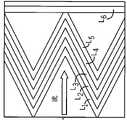
图9示出本发明的燃料水分离器的外部单元的实施例的截面图,示出介质层和配置。图9A示出不具有支撑中央管或筛板的实施例。图9B示出在无褶皱的介质柱体(6)的内部具有支撑中央管或筛板(7)的实施例。图9C示出在褶皱的介质柱体(1-5)和无褶皱的介质柱体(6)之间具有支撑中央管或筛板(7)的实施例。Figure 9 shows a cross-sectional view of an embodiment of the outer unit of the fuel water separator of the present invention, showing the media layers and configuration. Figure 9A shows an embodiment without a supporting central tube or frit. Figure 9B shows an embodiment with a supporting central tube or frit (7) inside the unpleated media column (6). Figure 9C shows an embodiment with a supporting central tube or frit (7) between the pleated media column (1-5) and the non-pleated media column (6).
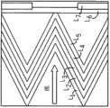
图10示出本发明的燃料水分离器的内部单元的实施例的截面图,其示出介质层和配置。Figure 10 shows a cross-sectional view of an embodiment of an internal unit of the fuel water separator of the present invention showing the media layers and configuration.
具体实施方式Detailed ways
本发明公开了模块化的滤中滤的单元,也就是外部过滤单元和内部过滤单元,可以被组装以形成以用于分离方方法和系统中使用的过滤筒的。模块化的滤中滤的单元和由其组装成的过滤筒可以进一步描述如下。The present invention discloses modular filter-in-filter units, ie, an outer filter unit and an inner filter unit, that can be assembled to form filter cartridges for use in separate methods and systems. The modular filter-in-filter units and filter cartridges assembled therefrom can be further described as follows.
外部过滤单元和内部过滤单元包括或利用包含一层或多层介质材料的介质,所述介质材料用于过滤连续相和分散相的混合物以及聚结分散相。这种介质在这里可以称为“聚结介质材料”。如本文所涉及的,一个或多个层可以具有期望的孔径、孔隙率和纤维直径。一个或多个层可以是均质的(即,包含一种材料)或者非均质的(即,包括混杂材料)。术语“孔径”、“孔隙率”和“纤维直径”可以指这些术语的“平均”或“均”值(例如,如果层是非均质的或着分级的,则对于这些均质层,“孔径”、“孔隙率”和“纤维直径”记录为平均孔径、平均孔隙率或平均纤维直径)。The outer and inner filtration units comprise or utilize media comprising one or more layers of media material for filtering a mixture of continuous and dispersed phases and coalescing the dispersed phase. Such media may be referred to herein as "coalescing media materials." As referred to herein, one or more layers may have a desired pore size, porosity, and fiber diameter. One or more layers may be homogeneous (ie, comprise one material) or heterogeneous (ie, comprise hybrid materials). The terms "pore size," "porosity," and "fiber diameter" may refer to the "average" or "average" value of these terms (e.g., if a layer is heterogeneous or graded, then for those homogeneous layers, "pore size ", "Porosity" and "Fiber Diameter" are reported as average pore diameter, average porosity, or average fiber diameter).
所公开的筒可以用在用于从连续相去除分散相的分离方法或系统。在一些实施例中,所公开的筒用于从含水液体分散在碳氢化合物液体的混合物中分离含水液体(例如,水)。如这里所关注的,碳氢化合物液体主要包括碳氢化合物材料,但是还可以包括非碳氢化合物材料(例如,高达约1%、5%、10%或20%的非碳氢化合物)。碳氢化合物液体可以包括碳氢化合物燃料。The disclosed cartridges may be used in a separation method or system for removing a dispersed phase from a continuous phase. In some embodiments, the disclosed cartridges are used to separate an aqueous liquid (eg, water) from a mixture of the aqueous liquid dispersed in a hydrocarbon liquid. As contemplated herein, hydrocarbon liquids primarily include hydrocarbon materials, but may also include non-hydrocarbon materials (eg, up to about 1%, 5%, 10%, or 20% non-hydrocarbons). Hydrocarbon liquids may include hydrocarbon fuels.
外部过滤单元和内部过滤单元可以包括编织材料或非编织材料。此外,外部过滤单元和内部过滤单元可以包括聚合介质或非聚合介质。适当的聚合材料可以包括、但是不限于聚酰胺材料、聚亚烷基对苯二甲酸材料(例如,聚对苯二甲酸乙二醇酯材料或聚对苯二甲酸丁二酯材料)、聚酯材料、卤烃材料(例如,Halar
外部过滤单元和内部过滤单元可以包括或使用多层介质。该介质可以通过熔喷两种不同的介质层(一层位于另一层的顶部),通过湿法造布工艺、电纺、电喷、熔纺、超声波结合、化学结合、物理结合、共褶皱或其他手段,或它们的结合形成。The outer filter unit and inner filter unit may comprise or use multiple layers of media. The media can be meltblown with two different media layers (one layer on top of the other), by wet-laid fabric process, electrospinning, electrospraying, melt spinning, ultrasonic bonding, chemical bonding, physical bonding, co-folding or other means, or a combination thereof.
外部过滤单元、内部过滤单元和由其组装的过滤筒可以用在现有技术中已知的过滤和聚结系统和方法中。(参见例如美国专利No.7,527,739、No.7,416,657、No.7,326,266、No.7,297,279、No.7,235,177、No.7,198,718、No.6,907,997、No.6,884,349、No.6,811,693、No.6,740,358、No.6,730,236、No.6,605,224、No.6,517,615、No.6,422,396、No.6,419,721、No.6,332,987、No.6,302,932、No.6,149,408、No.6,083,380、No.6,056,128、No.5,874,008、No.5,861,087、No.5,800,597、No.5,762,810、No.5,750,024、No.5,656,173、No.5,643,431、No.5,616,244、No.5,575,896、No.5,565,078、No.5,500,132、No.5,480,547、No.5,480,547、No.5,468,385、No.5,454,945、No.5,454,937、No.5,439,588、No.5,417,848、No.5,401,404、No.5,242,604、No.5,174,907、No.5,156,745、No.5,112,498、No.5,080,802、No.5,068,035、No.5,037,454、No.5,006,260、No.4,888,117、No.4,790,947、No.4,759,782、No.4,643,834、No.4,640,781、No.4,304,671、No.4,251,369、No.4,213,863、No.4,199,447、No.4,083,778、No.4,078,965、No.4,052,316、No.4,039,441、No.3,960,719、No.3,951,814以及美国专利申请公开No.2009-0020465、No.2009-0134097、No.2007-0289915、No.2007-0107399、No.2007-0062887、No.2007-0062886以及No.2007-0039865,这些专利或专利申请公开的全部内容以引用方式并入本文)。这里公开的聚结介质可以利用现有技术中已知的方法制造,并且可以包括现有技术中公开的附加特征。(参见例如上面提到的专利和专利申请公开以及美国专利No.6,767,459、No.5,443,724和No.4,081,373及美国专利申请公开No.2007-0131235、No.2007-0062887和No.2006-0242933,这些专利或专利申请公开的全部内容以引用方式并入本文)。The outer filter unit, inner filter unit and filter cartridges assembled therefrom may be used in filtration and coalescing systems and methods known in the art. (see, for example, U.S. Patent Nos. 7,527,739, .6,605,224、No.6,517,615、No.6,422,396、No.6,419,721、No.6,332,987、No.6,302,932、No.6,149,408、No.6,083,380、No.6,056,128、No.5,874,008、No.5,861,087、No.5,800,597、No.5,762,810 , No.5,750,024, No.5,656,173, No.5,643,431, No.5,616,244, No.5,575,896, No.5,565,078, No.5,500,132, No.5,480,547, No.5,480,547, No.5,468,345, No.5,93, .5,439,588、No.5,417,848、No.5,401,404、No.5,242,604、No.5,174,907、No.5,156,745、No.5,112,498、No.5,080,802、No.5,068,035、No.5,037,454、No.5,006,260、No.4,888,117、No.4,790,947 , No.4,759,782, No.4,643,834, No.4,640,781, No.4,304,671, No.4,251,369, No.4,213,863, No.4,199,447, No.4,083,778, No.4,078,965, No.4,052,313, No.4,49, .3,951,814 and U.S. Patent Application Publication Nos. 2009-0020465, 2009-0134097, 2007-0289915, 2007-0107399, 2007-0062887, 2007-0062886, and 2007-0039865, which The entire content of the patent or patent application publication is incorporated herein by reference). The coalescing media disclosed herein can be fabricated using methods known in the art, and can include additional features disclosed in the prior art. (See, eg, the patents and patent application publications mentioned above, as well as U.S. Patent Nos. 6,767,459, 5,443,724, and 4,081,373, and U.S. Patent Application Publication Nos. 2007-0131235, 2007-0062887, and 2006-0242933, which The entire content of the patent or patent application publication is incorporated herein by reference).
所公开的所组装的过滤筒可以用于从连续相(例如,碳氢化合物燃料)去除分散相(例如,水)。例如,所组装的过滤筒可以用于从连续相去除分散相,其中,在上述两相通过筒之后,分散相的至少约93%、95%、97%或99%被从连续相去除。The disclosed assembled filter cartridges can be used to remove a dispersed phase (eg, water) from a continuous phase (eg, hydrocarbon fuel). For example, the assembled filter cartridge can be used to remove a dispersed phase from a continuous phase, wherein at least about 93%, 95%, 97%, or 99% of the dispersed phase is removed from the continuous phase after the two phases pass through the cartridge.
这里描述的聚结介质可以包括具有独特的亲水性或疏水性,或者独特的亲油性或疏油性。在一些实施例中,聚结介质包括具有相对于混合物的分散相相对疏水的材料的材料层。在一些实施例中,外部过滤单元和内部过滤单元包括疏水的一层或多层介质材料。介质材料的疏水性性能可以通过测量连续相(例如,碳氢化合物燃料)中的分散相(例如,水)在介质材料上的接触角(θ)来获得。The coalescing media described herein can include uniquely hydrophilic or hydrophobic properties, or uniquely lipophilic or oleophobic properties. In some embodiments, the coalescing medium includes a layer of material having a material that is relatively hydrophobic relative to the dispersed phase of the mixture. In some embodiments, the outer filter unit and the inner filter unit comprise one or more layers of media material that are hydrophobic. The hydrophobic properties of the media material can be obtained by measuring the contact angle (θ) of the dispersed phase (eg, water) in the continuous phase (eg, hydrocarbon fuel) on the media material.
现在参见图1-5,示出的是外部过滤单元4、内部过滤单元6和由它们组装的过滤筒2的一个实施例。外部单元4包括柱体形的褶皱的过滤介质4a,该褶皱的过滤介质4a在褶皱的柱体的内部褶皱顶端与无褶皱的介质柱体4b直接或间接接触。褶皱的柱体和无褶皱的柱体在它们的端部粘接、罐装、埋设或以其它方式安装到位于柱体的相对的两端的封套(4c,顶端盖,4e,底端盖)。顶端盖4c可选地包括垫圈4d。无褶皱的柱体4b可以与褶皱的柱体4a的内部褶皱顶端直接或间接接触。典型地,褶皱的区段和无褶皱的柱体的内部顶端之间的距离使得,在所述顶端和柱体之间没有明显的间隙或间隔。内部单元6包括柱体形的外部无褶皱的过滤介质6a,该无褶皱的过滤介质6a与内部褶皱的介质柱体6b直接或间接接触。因而,内部单元的构造(即,外部无褶皱的过滤介质和内部褶皱的过滤介质)与外部过滤单元的构造(即,外部褶皱的过滤介质和内部无褶皱的过滤介质)相反。内部单元的无褶皱的柱体和褶皱的柱体在它们的端部粘接、罐装、埋设或以其它方式安装到位于柱体的相对的两端的封套(6c,顶端盖,6d,底端盖)。Referring now to Figures 1-5, shown is an embodiment of an
现在参见图6-8,示出的是热塑性的滤中滤的燃料水分离器(FWS)和本发明的粒子过滤器的一个实施例。图9示出当前公开的滤中滤的燃料水分离器(FWS)和粒子过滤器的外部单元的实施例的横向截面图。图9A示出不具有用于外部单元的介质的中央管、筛板或其它支撑结构的实施例。图9B示出用于位于无无褶皱的介质柱体的下游或与无褶皱的介质柱体临近介质的中央管、筛板或其它支撑结构的实施例。图9C示出具有用于在上游的褶皱的介质柱体和下游的无褶皱的介质柱体之间、与它们临近或与它们接触的介质的中央管、筛板或其它支撑结构的实施例。在图9中,数字1-5,按从上游向下游的顺序,指示无褶皱的介质柱体的不同介质层。数字6指示无褶皱的介质,数字7指示支撑外部单元的介质的结构,例如,中央管、筛板、弹簧等。如所示的,褶皱的柱体包括三层热塑性、纤维的纤维介质(层1-3)、一层热塑性纳米介质(层4)和最后的热塑性、纤维的介质层(层5)。如所示的,无褶皱的柱体包括形成为管、位于褶皱的介质柱体内侧、上游面与褶皱的介质柱体直接接触或者经由中间支撑结构(7)与褶皱的介质柱体间接接触的热塑性纤维的纤维层(层6)。可选的支撑结构(7)可以起防止无褶皱的柱体在筒用在燃料水分离系统时在流和压降下塌陷的作用。然而,褶皱的柱体和无褶皱的柱体一起提供足够的强度和刚性,使得支撑结构成为可选的。在图9C中,支撑结构为褶皱的柱体提供支撑,该褶皱的柱体的内部褶皱顶端与支撑构件直接接触,而无褶皱的柱体位于支撑结构的内侧、下游并且与支撑结构直接接触。在一些实施例中,无褶皱的柱体可以热熔接到热塑性中央管或与热塑性中央管一起注射成型,以使其固定到支撑结构。典型地,所有7层的轴向长度都相同。各个柱体的两端部埋设在端盖中,或者封装在诸如聚氨酯的粘接剂中,以将柱体的端部安装到端盖,并且防止在燃料水分离系统(图1-8)中使用的过程中未过滤的流体绕过介质周围。Referring now to FIGS. 6-8, shown is a thermoplastic filter-in-filter fuel water separator (FWS) and one embodiment of the particulate filter of the present invention. 9 shows a transverse cross-sectional view of an embodiment of an outer unit of the presently disclosed filter-in-filter fuel water separator (FWS) and particle filter. Figure 9A shows an embodiment without a central pipe, frit or other support structure for the media of the outer unit. Figure 9B shows an embodiment of a central tube, screen deck, or other support structure for media located downstream of or adjacent to an unpleated media column. Figure 9C shows an embodiment with a central pipe, frit or other support structure for the media between, adjacent to, or in contact with, an upstream pleated media column and a downstream unpleated media column. In FIG. 9, numerals 1-5, in order from upstream to downstream, indicate the different media layers of the unpleated media column.
图9B和9C的外部单元包括6层介质材料和支撑结构。然而,取决于使用过滤筒的系统的需求,外部单元可以包括更少或额外的层。仅为了说明的目的,在表1中描述被称为X、Y和Z的三种聚结器,包括这些聚结器的各介质层的典型性能。The external unit of Figures 9B and 9C includes 6 layers of dielectric material and support structures. However, the outer unit may include fewer or additional layers depending on the requirements of the system in which the filter cartridge is used. For illustrative purposes only, three coalescers, referred to as X, Y, and Z, are described in Table 1, including typical properties of the various media layers of these coalescers.

这三种聚结器的介质组合反应了基于如下观察的设计选择:在诸如ULSD和生物柴油的低界面张力系统中,存在较少的聚结用热动态驱动以及趋于慢的聚结动力。这些聚结器被设计成在物理上慢慢地降低连续相中的分散相的滴(例如,碳氢化合物燃料中的分散的水滴)经过介质的通过,并且增加所述滴在聚结器内局部地集中,以便于聚结和降低尺寸生长。These three coalescer media combinations reflect design choices based on the observation that in low interfacial tension systems such as ULSD and biodiesel, there is less thermodynamic drive for coalescence and coalescence kinetics tend to be slower. These coalescers are designed to physically slowly reduce the passage of droplets of the dispersed phase in the continuous phase (e.g., dispersed water droplets in hydrocarbon fuels) through the media, and to increase the passage of said droplets within the coalescer. Locally concentrated to facilitate coalescence and reduced size growth.
在聚结器X中,使用至少6个介质层及可选的支撑结构。聚结器X可以称为具有滤中滤的构造(见美国专利商标局公开US2009/0065419、US2009/0250402及US2010/0101993,它们的全部内容以引用方式并入本文)的“变速聚结器”(见PCT公开No.2010/042706,其全部内容以引用方式并入本文)。层1起预过滤器的作用,以减小跨越外部单元的压降。层1比层2“开放”(即,具有较高的孔隙率,较大的孔径、较大的平均纤维直径、较高的弗雷泽渗透性和/或较低的污染物去除效率)。层2起捕获小乳化滴的作用,例如,超低含硫柴油燃料中的水滴。层2比层3“紧密”(即,具有较低的孔隙率,较小的孔径、较小的平均纤维直径、较低的弗雷泽渗透性和/或较高的污染物去除效率)。层3起减小介质内的流体速度并且提供空间以供在层2中捕获的滴排出、聚积和聚结的作用。层3的物理性能使得该层中的流体速度低于层4中的流体速度。层3比层4“开放”(即,具有较高的孔隙率,较大的孔径、较大的平均纤维直径、较高的弗雷泽渗透性和/或较低的污染物去除效率)。层4起捕获未被之前的层捕获的滴、特别是更小的滴的作用,并且用作对所捕获的滴的通过具有半透过性的半透过性阻障。层4的该半透性阻障功能使滴在层3中集中和聚积,给滴更多时间并且使发生聚结的可能性更大。层4的该半透过性阻障功能还使局部增加的流体速度提高,并且使滴落物表面积瞬时增加,这进一步增强聚结。层4的物理性能使得该层中的流体速度高于层5中的流体速度。层4比层5“紧密”(即,具有较低的孔隙率,较小的孔径、较小的平均纤维直径、较低的弗雷泽渗透性和/或较高的污染物去除效率)。层4典型地是直径小于1μm的热塑性纳米纤维介质(例如,为了实现非常高的水去除效率需求,以为ULSD运行的现今的高压公轨柴油燃料系统或生物柴油聚集小滴尺寸)。层5起产生低速环境的功能,其中,在之前的层中形成的聚结的滴落物可以在释放之前收集和排出。层5比层4“开放”(即,具有较高的孔隙率,较大的孔径、较大的平均纤维直径、较高的弗雷泽渗透性和/或较低的污染物去除效率)。层6起到提供释放部位的作用,用于在低能环境中聚结滴落物。层6比层5“开放”(即,具有较高的孔隙率,较大的孔径、较大的平均纤维直径、较高的弗雷泽渗透性和/或较低的污染物去除效率)。In coalescer X, at least 6 media layers and optional support structures are used. Coalescer X may be referred to as a "variable speed coalescer" having a filter-in-filter configuration (see U.S. Patent and Trademark Office publications US2009/0065419, US2009/0250402, and US2010/0101993, the entire contents of which are incorporated herein by reference) (See PCT Publication No. 2010/042706, which is hereby incorporated by reference in its entirety). Layer 1 acts as a pre-filter to reduce the pressure drop across the external unit. Layer 1 is "open" (ie, has a higher porosity, larger pore size, larger average fiber diameter, higher Frazier permeability, and/or lower contaminant removal efficiency) than Layer 2. Layer 2 acts to trap small emulsified droplets, eg, water droplets in ultra-low sulfur diesel fuel. Layer 2 is "tighter" (ie, has lower porosity, smaller pore size, smaller average fiber diameter, lower Frazier permeability, and/or higher contaminant removal efficiency) than
在聚结器Y中,在具有或者不具有可选的支撑结构的情况下,使用两层或三层介质。聚结器Y可以称为具有滤中滤的构造(见美国专利商标局申请US2009/0065419、US2009/0250402及US2010/0101993,它们的全部内容以引用方式并入本文)的“单层表面聚结器”(见2009年5月15日提交的美国专利商标局申请No.61/178,738、2010年5月14日提交的公开号为No.2010/______的美国专利商标局申请No.12/780,392,它们的全部内容以引用的方式并入本文)。在聚结器Y中,层4起为小乳化滴的通过提供半透性的半透性阻障功能,使这些乳化滴在其上游表面集中。这样,滴具有足够的时间和适当的环境,用于聚结以及滴落物生长。层4是较“紧密”的层,与聚结器X中的层4的特征相比,甚至更紧密。该层利用“筛分”来防止小滴通过,并且典型地包括小有平均孔径M的热塑性纳米纤维过滤器介质,M小于流入滴的平均尺寸,最大孔径与平均孔径的比小于3(即,MM/M≤3)。在一些实施例中,水排出部存在于外部单元的上游面上,在层4的上游表面聚结的滴落物通过该水排出部排出,而在一些其它实施例中,水排出部可以存在于外部单元的下游侧,以通过跨越聚结单元的压降在释放部位收集已被强制通过介质的聚结的水。聚结器Y具有可选的层5,以为层4提供结构支撑,如果需要,用作任何被强制通过层4的聚结的滴落物用的排出路径。层5将层4连接到释放层6。层5还起产生低速、低能环境的功能,其中,在之前的层中形成的聚结的滴落物可以在释放之前收集和排出。层5比层4“开放”并且在构造上更强壮,以为层4提供支撑并且方便介质的加工。聚结器Y具有位于之前描述的层4和层5下游的额外的无褶皱的层6。层6起到为在低能环境中聚结的滴落物提供释放部位的作用。因而,层6比层5“开放”。In coalescer Y, two or three layers of media were used with or without optional support structures. Coalescer Y may be referred to as a "single layer surface coalescer" having a filter-in-filter configuration (see U.S. Patent and Trademark Office applications US2009/0065419, US2009/0250402, and US2010/0101993, the entire contents of which are incorporated herein by reference). device" (see USPTO Application No. 61/178,738, filed May 15, 2009, and USPTO Application No. 12/ 780, 392, which are hereby incorporated by reference in their entirety). In coalescer Y,
在聚结器Z中,使用具有可选的支撑结构的三层或更多层介质层(见2009年5月18日提交的美国专利商标局申请No.61/179,170、2010年5月14日提交的公开号为No.2010/______的美国专利商标局申请No.12/780,392,它们的全部内容以引用方式并入本文)。聚结器Z是比聚结器Y更复杂的表面聚结器,并且具有滤中滤的构造(见美国专利商标局公开US2009/0065419、US2009/0250402及US2010/0101993,它们的全部内容以引用方式并入本文)。层3起减小跨越聚结器的压降的功能,因此,用作聚结器用的粒子预过滤器以增加其使用寿命。层3比层4“开放”并且具有比层4高的毛细压力(即,更加正的毛细压力)。层4、5(可选)和层6的功能和性能和针对聚结器Y所描述的一样。In coalescer Z, three or more media layers with optional support structures are used (see USPTO Application No. 61/179,170, filed May 18, 2009, May 14, 2010 US Patent and Trademark Office Application No. 12/780,392, filed Publication No. 2010/______, the entire contents of which are incorporated herein by reference). Coalescer Z is a more complex surface coalescer than coalescer Y and has a filter-in-filter configuration (see USPTO Publications US2009/0065419, US2009/0250402, and US2010/0101993, the entire contents of which are incorporated by reference incorporated into this article).
在所有的三个聚结器X、Y和Z中,从层5到层6的过渡特性是重要的。层1-5典型地是褶皱的。因此,褶皱中的流体流动曲线和所捕获的滴落物的阻力使它们在褶皱的谷部(下游方向)聚集。这导致滴在该局部区域集中,通过提供增加的下降时间而增加聚结,以在它们被释放之前聚结。本发明人已经观察到,聚结的滴落物趋于在聚结器下游面的相同活性区域或地区释放,而在其它地方发生很少的滴落物释放。这建议一旦产生通过介质的排放路径,其就被重复使用。在本公开的过滤筒中,通过层4(用于聚结器Y和Z)或层5(用于聚结器X,如果包括该层,也用于聚结器Y和Z)与无褶皱的层6的上游表面直接接触,而产生优选的排出路径在大孔中的结束。在褶皱的和无褶皱的层之接接触的部位,存在介质孔结构的局部分布,这使这些优选的排放路径得以产生。这导致较大的滴落物得以释放。此外,这些排放路径发生在褶皱谷部的底部处,聚结的滴落物集中在这里并且效率最高。不需要层4或5与层6之间直接接触来实现该效果。例如,如图9C所示,褶皱的部分的最下游的层的内部褶皱顶端可以与多孔的支撑结构7直接接触,该支撑结构7进而与其下游侧的层6直接接触。In all three coalescers X, Y and Z, the transition characteristics from layer 5 to
在另一实施例(未图示)中,除了可以省略层6、无褶皱的释放层之外,褶皱的聚结器介质可以同在聚结器X、Y或Z中描述的一样。该构造使用与聚结器X、Y或Z相同的褶皱内的流体流动曲线和所捕获的滴落物阻力影响,以使滴和聚结的滴落物集中在褶皱的谷部中,以增强聚结。然而,代替聚结的滴落物排出到释放层、层6,滴落物从内部褶皱顶端中的小缝或孔释放。这些缝或孔可以通过针刺或其它手段产生,并且尺寸可以在30-300μm的数量级。内部褶皱顶端中的这些缝或孔用作用于聚结的滴落物的释放部位。In another embodiment (not shown), the pleated coalescer media can be as described for coalescers X, Y or Z, except that
本发明公开的过滤筒的内部单元起从燃料分离聚结的水滴落物以从流体去除小固体污染物的功能。内部单元包括与内部褶皱的柱体直接接触的外部无褶皱的柱体。典型地,无褶皱的和褶皱的柱体两者的轴向长度相同。各个柱体的两端部埋设在端盖中,或者封装在诸如聚氨酯的粘接剂中,以将柱体的端部安装到端盖,并且防止在燃料水分离系统(图1-8)中使用的过程中未过滤的流体绕过介质周围。The internal unit of the disclosed filter cartridge functions to separate coalesced water droplets from the fuel to remove small solid contaminants from the fluid. The inner unit comprises an outer uncorrugated cylinder in direct contact with an inner corrugated cylinder. Typically, both the uncorrugated and the corrugated cylinders are of the same axial length. Both ends of each column are embedded in the end cap or encapsulated in an adhesive such as polyurethane to mount the end of the column to the end cap and prevent the Unfiltered fluid bypasses around the media during use.
内部单元典型地包括至少四层介质材料(图10)第一层、层A的目的是从连续相(燃料)分离聚结的(水)滴落物。该层优选地包括管形式的编织的热塑性网,该网排斥滴落物并允许滴落物从表面自由地排出。层A位于内部褶皱的柱体的外侧并且与内部褶皱的柱体直接接触。该层的网孔典型地小于100μm,优选地,小于50μm。褶皱的层的功能是捕获未由外部过滤单元的上游的层去除的固体污染物和滴。这些褶皱的层的前两层,即图10和表2中的层B和C是用于减小压降的过渡层,以进一步去除滴落物和滴,减小固体在随后的纳米纤维过滤层、即层D的收集。层B还便于复合材料的制造和加工。The internal unit typically comprises at least four layers of dielectric material (Figure 10) The purpose of the first layer, layer A, is to separate coalesced (water) droplets from the continuous phase (fuel). This layer preferably comprises a woven thermoplastic mesh in the form of a tube which repels drips and allows drips to drain freely from the surface. Layer A is located on the outside of the inner corrugated cylinder and is in direct contact with the inner corrugated cylinder. The mesh of this layer is typically smaller than 100 μm, preferably smaller than 50 μm. The function of the pleated layers is to capture solid contaminants and droplets not removed by the layers upstream of the outer filter unit. The first two of these pleated layers, namely layers B and C in Figure 10 and Table 2, are transitional layers used to reduce pressure drop to further remove drips and droplets, reducing solids in subsequent nanofiber filtration A collection of layers, layer D. Layer B also facilitates fabrication and processing of the composite.

这些层具有与外部单元的层1和2相似的性能。下一褶皱的层,即图10和表2中的层D,用作小颗粒(例如,具有4μm或更小直径的颗粒)用的高效过滤器。对于高压供轨应用,对于4μm大小的颗粒的非常高的去除效率典型地需要保护燃料喷射器。层D上述的层主要用于去除和分离滴。层D用于保护下游系统不受小固体的污染。层D还用于去除可能已经通过前面的层的滴。优选地,层D比外部单元或内部单元的其它层中的任何层都“紧密”,并且包括直径小于1μm的热塑性纳米过滤介质。至少,内部单元的层D与外部单元的层4一种“紧密”。最后一层,即层E起在不明显增加压降的情况下为前面的层提供支持的功能。层E是具有在使用情况下足够支撑上游的层以便于内部单元介质的加工的强度和刚性的较“开放”的介质。These layers have similar properties to layers 1 and 2 of the external unit. The next pleated layer, layer D in Figure 10 and Table 2, acts as a high efficiency filter for small particles (eg, particles with a diameter of 4 μm or less). For high pressure rail applications, very high removal efficiencies for 4 μm sized particles are typically required to protect fuel injectors. Layer D The layers above are mainly used to remove and separate droplets. Layer D is used to protect downstream systems from contamination by small solids. Layer D also serves to remove drops that may have passed through previous layers. Preferably, layer D is "tighter" than any of the other layers of the outer unit or the inner unit, and comprises thermoplastic nanofiltration media having a diameter of less than 1 μm. At least layer D of the inner unit is "tight" with
在前述描述中,为了简单、清楚和便于理解,使用了特定术语。因为这些术语用于描述目的,并且期望获得宽泛的解释,所以其不会施加超过现有技术的要求的不必要的限制。这里描述的不同的构造、系统和方法步骤可以单独使用,或者与其它构造、系统和方法步骤结合起来使用。期望的是,各种等同、替代和变形是可能的。上述引用的专利和专利申请的全部内容以引用方式并入本文。In the foregoing description, specific terminology has been used for simplicity, clarity and understanding. Because these terms are used for descriptive purposes and are intended to be broadly interpreted, they do not impose unnecessary limitations beyond what is required by the prior art. The various configurations, systems and method steps described herein can be used alone or in combination with other configurations, systems and method steps. It is intended that various equivalents, substitutions and modifications are possible. The entire contents of the patents and patent applications cited above are incorporated herein by reference.
Claims (94)
Translated fromChineseApplications Claiming Priority (5)
| Application Number | Priority Date | Filing Date | Title |
|---|---|---|---|
| US12/820,791US8590712B2 (en) | 2008-10-08 | 2010-06-22 | Modular filter elements for use in a filter-in-filter cartridge |
| US12/820,791 | 2010-06-22 | ||
| US12/820,784US8517185B2 (en) | 2008-10-08 | 2010-06-22 | Two stage fuel water separator and particulate filter utilizing pleated nanofiber filter material |
| US12/820,784 | 2010-06-22 | ||
| PCT/US2011/031257WO2011162854A1 (en) | 2010-06-22 | 2011-04-05 | Modular filter elements for use in a filter-in-filter cartridge |
Publications (2)
| Publication Number | Publication Date |
|---|---|
| CN103025404Atrue CN103025404A (en) | 2013-04-03 |
| CN103025404B CN103025404B (en) | 2015-11-25 |
Family
ID=45371748
Family Applications (3)
| Application Number | Title | Priority Date | Filing Date |
|---|---|---|---|
| CN201180030353.0AActiveCN103025404B (en) | 2010-06-22 | 2011-04-05 | For the modular filtration units used in the cylinder filtered in filter |
| CN201180031592.8AActiveCN102946966B (en) | 2010-06-22 | 2011-04-05 | Secondary fuel water separator and particulate filter |
| CN201510982406.9AActiveCN105561650B (en) | 2010-06-22 | 2011-04-05 | Secondary fuel separator and particle filter |
Family Applications After (2)
| Application Number | Title | Priority Date | Filing Date |
|---|---|---|---|
| CN201180031592.8AActiveCN102946966B (en) | 2010-06-22 | 2011-04-05 | Secondary fuel water separator and particulate filter |
| CN201510982406.9AActiveCN105561650B (en) | 2010-06-22 | 2011-04-05 | Secondary fuel separator and particle filter |
Country Status (5)
| Country | Link |
|---|---|
| CN (3) | CN103025404B (en) |
| BR (2) | BR112012019395B1 (en) |
| DE (3) | DE112011102094B4 (en) |
| RU (3) | RU2557613C2 (en) |
| WO (2) | WO2011162855A1 (en) |
Cited By (9)
| Publication number | Priority date | Publication date | Assignee | Title |
|---|---|---|---|---|
| US9149749B2 (en) | 2012-11-13 | 2015-10-06 | Hollingsworth & Vose Company | Pre-coalescing multi-layered filter media |
| US9149748B2 (en) | 2012-11-13 | 2015-10-06 | Hollingsworth & Vose Company | Multi-layered filter media |
| CN107206298A (en)* | 2014-12-01 | 2017-09-26 | Ufi过滤股份公司 | The filter group of filter core and correlation with the device for draining |
| CN109069956A (en)* | 2016-04-18 | 2018-12-21 | 康明斯过滤Ip公司 | Nanofiber filter media for high performance applications |
| US10195542B2 (en) | 2014-05-15 | 2019-02-05 | Hollingsworth & Vose Company | Surface modified filter media |
| US10399024B2 (en) | 2014-05-15 | 2019-09-03 | Hollingsworth & Vose Company | Surface modified filter media |
| US10625196B2 (en) | 2016-05-31 | 2020-04-21 | Hollingsworth & Vose Company | Coalescing filter media |
| US10828587B2 (en) | 2015-04-17 | 2020-11-10 | Hollingsworth & Vose Company | Stable filter media including nanofibers |
| US11090590B2 (en) | 2012-11-13 | 2021-08-17 | Hollingsworth & Vose Company | Pre-coalescing multi-layered filter media |
Families Citing this family (16)
| Publication number | Priority date | Publication date | Assignee | Title |
|---|---|---|---|---|
| DE102014000597A1 (en)* | 2013-02-28 | 2014-08-28 | Mann + Hummel Gmbh | liquid filters |
| NZ721502A (en) | 2013-11-27 | 2018-03-23 | Atlas Copco Airpower Nv | High bulk coalescing filter media and use thereof |
| DE102014216979A1 (en)* | 2014-08-26 | 2016-03-03 | Mahle International Gmbh | final separator |
| EP3932516A1 (en)* | 2015-06-08 | 2022-01-05 | Saint-Gobain Performance Plastics Corporation | High pressure resistant filter |
| CN107847815A (en)* | 2015-07-08 | 2018-03-27 | 亚马逊过滤器有限责任公司 | For removing the piece-rate system of the solid particle and both drops that are suspended in another liquid simultaneously |
| DE102015218088A1 (en)* | 2015-09-21 | 2017-03-23 | Mahle International Gmbh | filtering device |
| DE102015014282A1 (en)* | 2015-11-06 | 2017-05-11 | Mann + Hummel Gmbh | Water separator and Wasserabscheidesystem clamped between two end plates held Endabscheidesieb |
| JP6647553B2 (en)* | 2016-03-01 | 2020-02-14 | Smc株式会社 | Filter element |
| WO2018136047A1 (en)* | 2017-01-18 | 2018-07-26 | Baldwin Filters, Inc. | Filter element with offset fluid passage |
| DE102017124251A1 (en) | 2017-10-18 | 2019-04-18 | KUENZEL advanced weaving technologies GmbH | Filter cartridge and filtration assembly with filter cartridge |
| US20190201816A1 (en)* | 2018-01-03 | 2019-07-04 | Goodrich Corporation | Double layer pleated media for seal with water purifier cartridge caps |
| CN113727771B (en) | 2019-02-08 | 2023-09-26 | 唐纳森公司 | Filter elements, air cleaner assemblies and methods |
| CN113950363B (en) | 2019-03-12 | 2023-07-11 | 帕克-汉尼芬公司 | Glass-free nonwoven coalescer |
| GB2590066B (en)* | 2019-11-13 | 2024-08-21 | Indufil BV | Apparatus and method |
| RU2755077C1 (en)* | 2020-12-28 | 2021-09-13 | Общество с ограниченной ответственностью "Экспертный технический центр ЦКБН" | Coalescing chuck |
| DE102022123809A1 (en)* | 2022-09-16 | 2024-03-21 | Hengst Se | Filter insert with improved filter performance under operating conditions |
Citations (5)
| Publication number | Priority date | Publication date | Assignee | Title |
|---|---|---|---|---|
| CN1684752A (en)* | 2002-09-26 | 2005-10-19 | 库诺公司 | Filter element comprising filter medium with multilayer pleated support structure |
| US20060137317A1 (en)* | 2004-12-28 | 2006-06-29 | Bryner Michael A | Filtration media for filtering particulate material from gas streams |
| CN101185818A (en)* | 2006-09-14 | 2008-05-28 | 大尼克株式会社 | air filter material |
| US7648565B2 (en)* | 2005-07-13 | 2010-01-19 | Parker-Hannifin Corporation | Filter element |
| US20100101993A1 (en)* | 2008-10-27 | 2010-04-29 | Cummins Filtration Ip Inc. | Filter cartridge having a filter within a filter, and an endplate sealing structure on an outer filter element |
Family Cites Families (85)
| Publication number | Priority date | Publication date | Assignee | Title |
|---|---|---|---|---|
| GB825192A (en)* | 1956-09-07 | 1959-12-09 | Bendix Aviat Corp | Vertical single element demulsifier filter assembly |
| US3847821A (en) | 1973-10-19 | 1974-11-12 | Minnesota Mining & Mfg | Separator for removing a dispersed liquid phase from a continuous liquid phase |
| US3960719A (en) | 1973-12-06 | 1976-06-01 | Phillips Petroleum Company | Coalescence filter for oil-water dispersions |
| US4039441A (en) | 1974-04-08 | 1977-08-02 | The De Laval Separator Company | Coalescing method and apparatus |
| US4199447A (en) | 1975-03-13 | 1980-04-22 | Imperial Chemical Industries Limited | Coalescence of oil in oil/water emulsions |
| DE2613870A1 (en) | 1975-04-10 | 1976-10-21 | Marine Constr & Design Co | METHOD AND DEVICE FOR COAGULATING |
| US4052316A (en) | 1975-07-07 | 1977-10-04 | Finite Filter Company | Composite coalescing filter tube |
| US4078965A (en) | 1975-07-07 | 1978-03-14 | Finite Filter Company | Composite coalescing filter tube and method of manufacture thereof |
| US4081373A (en) | 1977-05-26 | 1978-03-28 | The United States Of America As Represented By The Secretary Of The Army | Mechanism for exhausting impurities from engine fuel |
| FR2437860A2 (en) | 1978-10-02 | 1980-04-30 | Degremont | METHOD AND APPARATUS FOR SEPARATING COALESCENT EMULSIONS |
| US4213863A (en) | 1979-01-08 | 1980-07-22 | Marine Construction & Design Co. | Flow-through coalescing separator |
| US4251369A (en) | 1979-06-11 | 1981-02-17 | Conoco, Inc. | Radial design submerged coalescer for separation of liquids |
| GB8417783D0 (en) | 1984-07-12 | 1984-08-15 | Shell Int Research | Treating liquids |
| US4790947A (en) | 1985-05-20 | 1988-12-13 | Arnold Kenneth E | Water treating in a vertical series coalescing flume |
| US5439588A (en) | 1985-07-05 | 1995-08-08 | Kalsep Limited | Coalescing filter using an expandable bed fiber |
| US5174907A (en) | 1985-07-05 | 1992-12-29 | Kalsen Limited | Method of filtering using an expandable bed fiber and coalescer |
| US4759782A (en) | 1985-07-05 | 1988-07-26 | Pall Corporation | Coalescing filter for removal of liquid aerosols from gaseous streams |
| SU1337536A1 (en)* | 1985-12-06 | 1987-09-15 | Кузбасский Политехнический Институт | Full-flow oil filter for internal combustion engine |
| US4643834A (en) | 1986-02-03 | 1987-02-17 | Filter Plate Company | Separation system using coalescing techniques |
| FR2607403B1 (en) | 1986-11-28 | 1991-02-22 | Toulouse Inst Nal Sciences App | METHOD AND DEVICE FOR SEPARATING AN EMULSION OR SUSPENSION DISPERSE PHASE IN A CONTINUOUS PHASE |
| US5037454A (en) | 1987-04-13 | 1991-08-06 | Mann Technology Limited Partnership | Coalescing apparatus and method |
| GB8711931D0 (en) | 1987-05-20 | 1987-06-24 | British Petroleum Co Plc | Filtration/coalescence |
| GB2239191B (en) | 1989-11-28 | 1993-04-14 | Orkney Water Test Centre Limit | A method of coalescing a disperse phase within a continuous phase of a fluid mixture |
| SU1813498A1 (en)* | 1990-02-20 | 1993-05-07 | Kuzbasskij Politekhn I | Filtering member |
| US5156745A (en) | 1990-05-09 | 1992-10-20 | Cairo Jr John A | Induced gas liquid coalescer and flotation separator |
| US5080802A (en) | 1990-05-09 | 1992-01-14 | Cairo Jr John A | Induced gas liquid coalescer and flotation separator |
| SU1761201A1 (en)* | 1990-06-07 | 1992-09-15 | Научно-исследовательский институт полупроводникового машиностроения | Filtrating element |
| US5068035A (en) | 1991-01-28 | 1991-11-26 | Facet Quantek, Inc. | Coalescing plate packing system |
| US5242604A (en) | 1992-01-10 | 1993-09-07 | Sudden Service Co. | Lateral flow coalescing multiphase plate separator |
| US5454945A (en) | 1992-08-31 | 1995-10-03 | Porous Media Corporation | Conical coalescing filter and assembly |
| DE4325745C2 (en) | 1992-09-04 | 1995-03-09 | Mann & Hummel Filter | Coalescence separator with vortex-free operation |
| US5750024A (en) | 1992-11-12 | 1998-05-12 | Porous Media Corporation | Conical coalescing filter |
| US5443724A (en) | 1992-12-23 | 1995-08-22 | Pall Corporation | Apparatus for separating the components of a liquid/liquid mixture |
| US5401404A (en) | 1993-01-21 | 1995-03-28 | Strauss; Richard | Stacked disk coalescer |
| US5500132A (en) | 1993-08-27 | 1996-03-19 | Modern Welding Company, Inc. | Liquid to liquid coalescing separator and method |
| JPH07106283B2 (en) | 1993-10-07 | 1995-11-15 | 有限会社ゼオテック | Charge coalescer type oil / water separator |
| US5480547A (en) | 1994-03-08 | 1996-01-02 | Pall Corporation | Corrosive liquid coalescer |
| US5565078A (en) | 1994-04-06 | 1996-10-15 | National Tank Company | Apparatus for augmenting the coalescence of water in a water-in-oil emulsion |
| US5575896A (en) | 1994-04-06 | 1996-11-19 | National Tank Company | Method and apparatus for oil/water separation using a dual electrode centrifugal coalescer |
| US5454937A (en) | 1994-09-19 | 1995-10-03 | Lewandowski; Adam F. | Collant filter and oil coalescer |
| FR2732234B1 (en) | 1995-03-31 | 1997-05-23 | Elf Aquitaine | CYCLONE SEPARATOR HAVING INCORPORATED COALESCER |
| US6083380A (en) | 1995-04-20 | 2000-07-04 | Tannas Co. | Fluid coalescing method and apparatus |
| US5656173A (en) | 1996-03-05 | 1997-08-12 | National Tank Company | Method of removing dispersed oil from an oil in water emulsion employing aerated solutions within a coalescing media |
| US5800597A (en) | 1997-01-21 | 1998-09-01 | Whatman Inc. | Integral coalescer filter-membrane device to provide a filtered gas stream and system employing such device |
| DE69723714T2 (en) | 1996-09-30 | 2004-04-15 | Pall Corp. | coalescing |
| US5861087A (en) | 1996-11-12 | 1999-01-19 | National Tank Company | Apparatus for augmenting the coalescence of a component of an oil/water mixture |
| US5762810A (en) | 1996-11-22 | 1998-06-09 | Pelton; Paul | Coalescing oil/water separator |
| AU742504B2 (en) | 1997-04-08 | 2002-01-03 | Rohm And Haas Company | Reactive coalescents |
| US5874008A (en) | 1997-08-13 | 1999-02-23 | Hirs; Gene | Purification of machine tool coolant via tramp oil injection to effectuate coalescence of target contaminant tramp oil |
| GB2335867A (en) | 1998-04-03 | 1999-10-06 | Process Scient Innovations | Thermally bonded felt material for coalescence filters |
| GB9813864D0 (en) | 1998-06-27 | 1998-08-26 | Ert Limited | Two phase liquid media coalescer |
| US6056128A (en) | 1998-08-04 | 2000-05-02 | Glasgow; James A. | Coalescer with removable cartridge |
| US6302932B1 (en) | 1998-11-12 | 2001-10-16 | Honeywell International, Inc. | Combined water coalescer odor removal filter for use in water separation systems |
| GB9902220D0 (en) | 1999-02-01 | 1999-03-24 | Cyclotech Limited | Fluid processing |
| US6149408A (en) | 1999-02-05 | 2000-11-21 | Compressor Systems, Inc. | Coalescing device and method for removing particles from a rotary gas compressor |
| US6422396B1 (en) | 1999-09-16 | 2002-07-23 | Kaydon Custom Filtration Corporation | Coalescer for hydrocarbons containing surfactant |
| NO312404B1 (en) | 2000-05-05 | 2002-05-06 | Aibel As | In-line electrostatic coalescents with double helical electrodes |
| US6517615B2 (en) | 2001-02-08 | 2003-02-11 | Dynetek Industries Ltd. | Coalescing filter assembly |
| US6605224B2 (en) | 2001-07-24 | 2003-08-12 | Highland Tank And Manufacturing Company | Coalescer apparatus in an oil/water separator |
| US6730236B2 (en) | 2001-11-08 | 2004-05-04 | Chevron U.S.A. Inc. | Method for separating liquids in a separation system having a flow coalescing apparatus and separation apparatus |
| US6913251B2 (en) | 2003-02-12 | 2005-07-05 | William B. Kerfoot | Deep well sparging |
| US6907997B2 (en) | 2003-02-19 | 2005-06-21 | Hancor, Inc. | Water clarification system with coalescing plates |
| US7235177B2 (en) | 2003-04-23 | 2007-06-26 | Fleetguard, Inc. | Integral air/oil coalescer for a centrifuge |
| US7326266B2 (en) | 2003-10-31 | 2008-02-05 | Flair Corporation | Coalescing type filter apparatus and method |
| RU39502U1 (en)* | 2003-12-03 | 2004-08-10 | Общество с ограниченной ответственностью "ЭЛГАЗ-В" | FILTER SEPARATOR ELEMENT FOR CLEANING FUEL |
| RU38450U1 (en)* | 2004-01-23 | 2004-06-20 | Ионов Александр Павлович | FILTER WATER SEPARATOR AND FILTER ELEMENT |
| US6884349B1 (en) | 2004-04-12 | 2005-04-26 | Fleetguard, Inc. | Oval centerpost and cooperating filter cartridge |
| US8057567B2 (en) | 2004-11-05 | 2011-11-15 | Donaldson Company, Inc. | Filter medium and breather filter structure |
| US7297279B2 (en) | 2005-01-21 | 2007-11-20 | Amcol International Corporation | Method for removing oil from water coalescing in a polymer particle/fiber media |
| US8057669B2 (en) | 2005-02-22 | 2011-11-15 | Baldwin Filters, Inc. | Filter element and filter assembly including locking mechanism |
| US7527739B2 (en) | 2005-08-15 | 2009-05-05 | Fleetguard Inc | Apparatus, system, and method for multistage water separation |
| US20070062886A1 (en) | 2005-09-20 | 2007-03-22 | Rego Eric J | Reduced pressure drop coalescer |
| US7674425B2 (en) | 2005-11-14 | 2010-03-09 | Fleetguard, Inc. | Variable coalescer |
| US8114183B2 (en) | 2005-09-20 | 2012-02-14 | Cummins Filtration Ip Inc. | Space optimized coalescer |
| DE202006004529U1 (en) | 2006-03-20 | 2007-08-02 | Hengst Gmbh & Co.Kg | Filter insert for a motor vehicle's oil/fuel filter has an end plate and a filter medium to be fitted in a filter's filter chamber |
| US7416657B2 (en) | 2006-03-21 | 2008-08-26 | Nexjen Technologies Ltd. | Oil water coalescing separator |
| WO2007149497A2 (en) | 2006-06-20 | 2007-12-27 | Cummins Filtration Inc. | Replaceable filter elements including plural filter media and related filtration systems, tecniques and methods |
| US8017011B2 (en)* | 2006-08-30 | 2011-09-13 | Kaydon Custom Filtration Corporation | Pleated single phase filter coalescer element and method |
| US7867387B2 (en) | 2007-07-19 | 2011-01-11 | Cummins Filtration Ip, Inc. | Standpipe with flow restriction valve, and filter cartridge |
| US8002990B2 (en)* | 2007-07-27 | 2011-08-23 | Kx Technologies, Llc | Uses of fibrillated nanofibers and the removal of soluble, colloidal, and insoluble particles from a fluid |
| RU2371235C2 (en)* | 2007-08-09 | 2009-10-27 | ООО "Волгоградская машиностроительная компания "ВгТЗ" | Filter |
| US7857974B2 (en) | 2007-09-06 | 2010-12-28 | Cummins Filtration Ip, Inc. | Filter cartridge with snap fit connection |
| WO2009058598A2 (en) | 2007-11-01 | 2009-05-07 | Shawndra Products, Incorporated | Hydrogen sulfide filter |
| US8360251B2 (en) | 2008-10-08 | 2013-01-29 | Cummins Filtration Ip, Inc. | Multi-layer coalescing media having a high porosity interior layer and uses thereof |
| CN105477903B (en) | 2009-05-15 | 2017-12-12 | 康明斯过滤Ip公司 | Surface coalescer |
- 2011
- 2011-04-05CNCN201180030353.0Apatent/CN103025404B/enactiveActive
- 2011-04-05RURU2013102593/05Apatent/RU2557613C2/enactive
- 2011-04-05DEDE112011102094.5Tpatent/DE112011102094B4/enactiveActive
- 2011-04-05CNCN201180031592.8Apatent/CN102946966B/enactiveActive
- 2011-04-05RURU2015124044Apatent/RU2654979C1/enactive
- 2011-04-05BRBR112012019395-3Apatent/BR112012019395B1/enactiveIP Right Grant
- 2011-04-05DEDE112011102095.3Tpatent/DE112011102095B4/enactiveActive
- 2011-04-05BRBR112012019483-6Apatent/BR112012019483B1/enactiveIP Right Grant
- 2011-04-05WOPCT/US2011/031259patent/WO2011162855A1/enactiveApplication Filing
- 2011-04-05RURU2013102594/05Apatent/RU2561993C2/enactive
- 2011-04-05DEDE112011106183.8Tpatent/DE112011106183B4/enactiveActive
- 2011-04-05CNCN201510982406.9Apatent/CN105561650B/enactiveActive
- 2011-04-05WOPCT/US2011/031257patent/WO2011162854A1/enactiveApplication Filing
Patent Citations (5)
| Publication number | Priority date | Publication date | Assignee | Title |
|---|---|---|---|---|
| CN1684752A (en)* | 2002-09-26 | 2005-10-19 | 库诺公司 | Filter element comprising filter medium with multilayer pleated support structure |
| US20060137317A1 (en)* | 2004-12-28 | 2006-06-29 | Bryner Michael A | Filtration media for filtering particulate material from gas streams |
| US7648565B2 (en)* | 2005-07-13 | 2010-01-19 | Parker-Hannifin Corporation | Filter element |
| CN101185818A (en)* | 2006-09-14 | 2008-05-28 | 大尼克株式会社 | air filter material |
| US20100101993A1 (en)* | 2008-10-27 | 2010-04-29 | Cummins Filtration Ip Inc. | Filter cartridge having a filter within a filter, and an endplate sealing structure on an outer filter element |
Cited By (16)
| Publication number | Priority date | Publication date | Assignee | Title |
|---|---|---|---|---|
| US10279291B2 (en) | 2012-11-13 | 2019-05-07 | Hollingsworth & Vose Company | Pre-coalescing multi-layered filter media |
| US9149748B2 (en) | 2012-11-13 | 2015-10-06 | Hollingsworth & Vose Company | Multi-layered filter media |
| US9149749B2 (en) | 2012-11-13 | 2015-10-06 | Hollingsworth & Vose Company | Pre-coalescing multi-layered filter media |
| US10080985B2 (en) | 2012-11-13 | 2018-09-25 | Hollingsworth & Vose Company | Multi-layered filter media |
| US11090590B2 (en) | 2012-11-13 | 2021-08-17 | Hollingsworth & Vose Company | Pre-coalescing multi-layered filter media |
| US11266941B2 (en) | 2014-05-15 | 2022-03-08 | Hollingsworth & Vose Company | Surface modified filter media |
| US10195542B2 (en) | 2014-05-15 | 2019-02-05 | Hollingsworth & Vose Company | Surface modified filter media |
| US10399024B2 (en) | 2014-05-15 | 2019-09-03 | Hollingsworth & Vose Company | Surface modified filter media |
| CN107206298B (en)* | 2014-12-01 | 2019-08-20 | Ufi过滤股份公司 | Filter cartridges and associated filter packs with means for drainage |
| CN107206298A (en)* | 2014-12-01 | 2017-09-26 | Ufi过滤股份公司 | The filter group of filter core and correlation with the device for draining |
| US10828587B2 (en) | 2015-04-17 | 2020-11-10 | Hollingsworth & Vose Company | Stable filter media including nanofibers |
| US11819789B2 (en) | 2015-04-17 | 2023-11-21 | Hollingsworth & Vose Company | Stable filter media including nanofibers |
| CN109069956A (en)* | 2016-04-18 | 2018-12-21 | 康明斯过滤Ip公司 | Nanofiber filter media for high performance applications |
| US11633682B2 (en) | 2016-04-18 | 2023-04-25 | Cummins Filtration Ip, Inc. | Nanofiber filter media for high performance applications |
| US10625196B2 (en) | 2016-05-31 | 2020-04-21 | Hollingsworth & Vose Company | Coalescing filter media |
| US11338239B2 (en) | 2016-05-31 | 2022-05-24 | Hollingsworth & Vose Company | Coalescing filter media |
Also Published As
| Publication number | Publication date |
|---|---|
| RU2013102594A (en) | 2014-07-27 |
| BR112012019395A8 (en) | 2019-09-10 |
| WO2011162855A1 (en) | 2011-12-29 |
| BR112012019395B1 (en) | 2020-09-29 |
| BR112012019483B1 (en) | 2020-12-22 |
| DE112011102094T5 (en) | 2013-07-18 |
| RU2557613C2 (en) | 2015-07-27 |
| RU2561993C2 (en) | 2015-09-10 |
| CN102946966B (en) | 2016-01-27 |
| DE112011102095B4 (en) | 2022-02-17 |
| RU2654979C1 (en) | 2018-05-23 |
| DE112011106183B4 (en) | 2025-10-16 |
| CN102946966A (en) | 2013-02-27 |
| WO2011162854A1 (en) | 2011-12-29 |
| BR112012019395A2 (en) | 2018-03-20 |
| CN105561650A (en) | 2016-05-11 |
| CN105561650B (en) | 2018-11-27 |
| DE112011102094B4 (en) | 2024-12-19 |
| BR112012019483A2 (en) | 2018-03-27 |
| DE112011102095T5 (en) | 2013-07-18 |
| CN103025404B (en) | 2015-11-25 |
| RU2013102593A (en) | 2014-07-27 |
Similar Documents
| Publication | Publication Date | Title |
|---|---|---|
| CN103025404B (en) | For the modular filtration units used in the cylinder filtered in filter | |
| US8590712B2 (en) | Modular filter elements for use in a filter-in-filter cartridge | |
| CN102596862B (en) | Surface coalescer | |
| CN204865249U (en) | Coalescer and condense medium | |
| US8517185B2 (en) | Two stage fuel water separator and particulate filter utilizing pleated nanofiber filter material | |
| CN102893015B (en) | A kind of internal combustion engine fuel filter group of improvement and filter core thereof | |
| JP4422799B2 (en) | Coalescer element | |
| US8360251B2 (en) | Multi-layer coalescing media having a high porosity interior layer and uses thereof | |
| US20120292252A1 (en) | Tubular surface coalescers | |
| CN106413834B (en) | Filtration structure, cartridge and filter assembly for fuel | |
| US11596888B2 (en) | Coalescence filter | |
| US20210402326A1 (en) | Glass-free nonwoven coalescer | |
| EP3458176B1 (en) | A filter structure for separation of water from fluids in the motor vehicle sector |
Legal Events
| Date | Code | Title | Description |
|---|---|---|---|
| C06 | Publication | ||
| PB01 | Publication | ||
| C10 | Entry into substantive examination | ||
| SE01 | Entry into force of request for substantive examination | ||
| C14 | Grant of patent or utility model | ||
| GR01 | Patent grant |