CN103024264A - Image pickup apparatus and focus detection method - Google Patents
Image pickup apparatus and focus detection methodDownload PDFInfo
- Publication number
- CN103024264A CN103024264ACN2012103695906ACN201210369590ACN103024264ACN 103024264 ACN103024264 ACN 103024264ACN 2012103695906 ACN2012103695906 ACN 2012103695906ACN 201210369590 ACN201210369590 ACN 201210369590ACN 103024264 ACN103024264 ACN 103024264A
- Authority
- CN
- China
- Prior art keywords
- image
- correlation data
- pixel
- focus detection
- correlation
- Prior art date
- Legal status (The legal status is an assumption and is not a legal conclusion. Google has not performed a legal analysis and makes no representation as to the accuracy of the status listed.)
- Granted
Links
- 238000001514detection methodMethods0.000titleclaimsabstractdescription88
- 238000004364calculation methodMethods0.000claimsabstractdescription80
- 238000003384imaging methodMethods0.000claimsabstractdescription58
- 210000001747pupilAnatomy0.000claimsabstractdescription20
- 230000003287optical effectEffects0.000claimsdescription27
- 230000008859changeEffects0.000claimsdescription7
- 238000006243chemical reactionMethods0.000claimsdescription6
- 230000007274generation of a signal involved in cell-cell signalingEffects0.000claimsdescription2
- 238000000034methodMethods0.000description12
- 230000014509gene expressionEffects0.000description8
- 230000008569processEffects0.000description3
- 238000004590computer programMethods0.000description2
- 230000000694effectsEffects0.000description2
- 230000006870functionEffects0.000description2
- 230000002093peripheral effectEffects0.000description2
- 230000004044responseEffects0.000description2
- 230000015572biosynthetic processEffects0.000description1
- 230000015556catabolic processEffects0.000description1
- 238000006731degradation reactionMethods0.000description1
- 239000006185dispersionSubstances0.000description1
- 238000006073displacement reactionMethods0.000description1
- 238000012986modificationMethods0.000description1
- 230000004048modificationEffects0.000description1
- 238000005375photometryMethods0.000description1
- 239000004065semiconductorSubstances0.000description1
Images


Classifications
- G—PHYSICS
- G02—OPTICS
- G02B—OPTICAL ELEMENTS, SYSTEMS OR APPARATUS
- G02B7/00—Mountings, adjusting means, or light-tight connections, for optical elements
- G02B7/28—Systems for automatic generation of focusing signals
- G02B7/34—Systems for automatic generation of focusing signals using different areas in a pupil plane
- H—ELECTRICITY
- H04—ELECTRIC COMMUNICATION TECHNIQUE
- H04N—PICTORIAL COMMUNICATION, e.g. TELEVISION
- H04N23/00—Cameras or camera modules comprising electronic image sensors; Control thereof
- H04N23/60—Control of cameras or camera modules
- H04N23/67—Focus control based on electronic image sensor signals
- H04N23/672—Focus control based on electronic image sensor signals based on the phase difference signals
- H—ELECTRICITY
- H04—ELECTRIC COMMUNICATION TECHNIQUE
- H04N—PICTORIAL COMMUNICATION, e.g. TELEVISION
- H04N25/00—Circuitry of solid-state image sensors [SSIS]; Control thereof
- H04N25/70—SSIS architectures; Circuits associated therewith
- H04N25/703—SSIS architectures incorporating pixels for producing signals other than image signals
- H04N25/704—Pixels specially adapted for focusing, e.g. phase difference pixel sets
- H—ELECTRICITY
- H10—SEMICONDUCTOR DEVICES; ELECTRIC SOLID-STATE DEVICES NOT OTHERWISE PROVIDED FOR
- H10F—INORGANIC SEMICONDUCTOR DEVICES SENSITIVE TO INFRARED RADIATION, LIGHT, ELECTROMAGNETIC RADIATION OF SHORTER WAVELENGTH OR CORPUSCULAR RADIATION
- H10F39/00—Integrated devices, or assemblies of multiple devices, comprising at least one element covered by group H10F30/00, e.g. radiation detectors comprising photodiode arrays
- H10F39/80—Constructional details of image sensors
Landscapes
- Physics & Mathematics (AREA)
- Engineering & Computer Science (AREA)
- Multimedia (AREA)
- Signal Processing (AREA)
- General Physics & Mathematics (AREA)
- Optics & Photonics (AREA)
- Focusing (AREA)
- Automatic Focus Adjustment (AREA)
- Studio Devices (AREA)
Abstract
Translated fromChinese
Description
Translated fromChinese技术领域technical field
本发明涉及一种通过使用来自用于对被摄体图像进行光电转换的图像传感器的输出来检测摄像光学系统的焦点状态的摄像设备。The present invention relates to an imaging apparatus that detects a focus state of an imaging optical system by using an output from an image sensor for photoelectrically converting a subject image.
背景技术Background technique
这种摄像设备利用图像传感器内所设置的多个焦点检测像素来对穿过摄像光学系统的出射光瞳中彼此不同的两个区域(以下称为“两个光瞳区域”)的光束所形成的一对被摄体图像进行光电转换,以根据焦点检测像素产生一对图像信号。摄像设备对一对图像信号进行相关计算以计算一对图像信号之间的作为相对位置差量(图像偏移量)的相位差,然后计算与摄像光学系统的焦点状态相对应的散焦量。这种焦点检测方法被称为“图像传感器相位差检测方法”。Such an image pickup apparatus utilizes a plurality of focus detection pixels provided in the image sensor to form an image of light beams passing through two regions (hereinafter referred to as "two pupil regions") different from each other in the exit pupil of the image pickup optical system. A pair of subject images are photoelectrically converted to generate a pair of image signals based on the focus detection pixels. The imaging apparatus performs correlation calculation on a pair of image signals to calculate a phase difference between the pair of image signals as a relative position difference amount (image shift amount), and then calculates a defocus amount corresponding to the focus state of the imaging optical system. This focus detection method is called "image sensor phase difference detection method".
日本特许2001-083407和日本特开2001-250931公开了各自设置有如下图像传感器的摄像设备,其中该图像传感器的各焦点检测像素包括具有集光作用的一个微透镜以及分别接收来自两个不同光瞳区域的光束的两个分割光电二级管(以下简称为“PD”)。将多个这种焦点检测像素设置在图像传感器内,这使得能够产生该对图像信号。Japanese Patent No. 2001-083407 and Japanese Patent Application Laid-Open No. 2001-250931 disclose image pickup devices each provided with an image sensor in which each focus detection pixel of the image sensor includes a microlens having a light-collecting effect and receives light from two different Two split photodiodes (hereinafter abbreviated as "PD") for the beam in the pupil region. Providing a plurality of such focus detection pixels within the image sensor enables generation of the pair of image signals.
此外,日本特许3592147和日本特开2010-152161公开了各自设置有包括如下两个焦点检测像素组的图像传感器的摄像设备,其中在这两个焦点检测像素组中,形成在光入射侧的位于PD前的配线层的开口相对于像素中心在彼此不同的方向上偏移。设置用于接收来自两个光瞳区域的光束的这两个焦点检测像素组,这使得能够产生一对图像信号。Furthermore, Japanese Patent No. 3592147 and Japanese Patent Laid-Open No. 2010-152161 disclose image pickup apparatuses each provided with an image sensor including two focus detection pixel groups in which the The openings of the wiring layer in front of the PD are shifted in directions different from each other with respect to the center of the pixel. The two focus detection pixel groups for receiving light beams from the two pupil areas are provided, which enables generation of a pair of image signals.
在这种图像传感器相位差检测方法中,期望从设置在图像传感器内的作为包括多个像素行和多个像素列的二维像素区域的焦点检测区域中获得各图像信号。这是因为:仅包括一个像素行的焦点检测区域太窄以至于无法进行良好的焦点检测。因而,日本特开2010-152161所公开的摄像设备使各像素行所包括的多个像素的输出沿像素行延伸的方向进行投影,从而产生各像素行的输出。In such an image sensor phase difference detection method, it is desirable to obtain each image signal from a focus detection area provided in the image sensor as a two-dimensional pixel area including a plurality of pixel rows and a plurality of pixel columns. This is because a focus detection area including only one pixel row is too narrow to perform good focus detection. Therefore, the imaging device disclosed in Japanese Patent Application Laid-Open No. 2010-152161 projects the outputs of a plurality of pixels included in each pixel row in the direction in which the pixel row extends, thereby generating the output of each pixel row.
然后,在像素列延伸的方向上配置各个像素行的输出,这使得能够从二维焦点检测区域产生一维图像信号。此外,日本特开2010-152161公开了一种方法,其针对各像素行产生一对图像信号,计算该对图像信号之间的相位差(图像偏移量),然后相加针对多个像素行而计算出的图像偏移量,从而计算二维焦点检测区域的图像偏移量。Then, the output of each pixel row is arranged in the direction in which the pixel column extends, which enables generation of a one-dimensional image signal from a two-dimensional focus detection area. Furthermore, Japanese Patent Laid-Open No. 2010-152161 discloses a method of generating a pair of image signals for each pixel row, calculating the phase difference (image offset) between the pair of image signals, and adding And the calculated image offset, thereby calculating the image offset of the two-dimensional focus detection area.
然而,日本特开2010-152161所公开的图像信号产生方法中的第一种方法将二维配置的像素的输出压缩成一维输出,由此使针对诸如横线等的特定被摄体的焦点检测性能劣化。另一方面,日本特开2010-152161所公开的图像信号产生方法中的第二种方法要求针对各像素行计算图像偏移量,这虽然能够确保一定程度的焦点检测性能,但是需要较长的计算时间。However, the first method among the image signal generating methods disclosed in Japanese Patent Laid-Open No. 2010-152161 compresses the output of two-dimensionally arranged pixels into a one-dimensional output, thereby enabling focus detection for a specific subject such as a horizontal line. Performance degradation. On the other hand, the second method among the image signal generating methods disclosed in Japanese Patent Laid-Open No. 2010-152161 requires calculating the image shift amount for each pixel row, which can ensure a certain degree of focus detection performance, but requires a long time. calculating time.
发明内容Contents of the invention
本发明的一个方面提供一种摄像设备,包括:图像传感器,其包括多个像素,其中所述多个像素用于对穿过摄像光学系统的出射光瞳的不同区域的光束所分别形成的被摄体图像对进行光电转换;信号产生部件,用于通过使用来自所述图像传感器的焦点检测区域所包括的多个像素线中的各个像素线的输出,针对所述多个像素线中的各个像素线,来产生与所述被摄体图像对相对应的图像信号对,其中各个像素线包括所述多个像素中在第一方向上排列的多个像素,并且所述多个像素线在与所述第一方向垂直的第二方向上排列;以及计算部件,用于通过使用针对各个像素线所产生的所述图像信号对,来计算所述摄像光学系统的散焦量,其中,所述计算部件被配置为:针对各个像素线,通过使所述图像信号对在所述第一方向上进行相对移位并针对各相对移位量计算相关值,来产生第一相关数据,将针对各个像素线所产生的第一相关数据的相应相关值进行相加以产生第二相关数据,以及根据所述第二相关数据来计算所述散焦量。One aspect of the present invention provides an imaging device, including: an image sensor including a plurality of pixels, wherein the plurality of pixels are used to respectively form beams passing through different areas of the exit pupil of the imaging optical system to be performing photoelectric conversion on the subject image; a signal generating section configured to, for each of the plurality of pixel lines included in the focus detection area of the image sensor, use an output from each of the plurality of pixel lines pixel lines to generate image signal pairs corresponding to the subject image pairs, wherein each pixel line includes a plurality of pixels arranged in a first direction among the plurality of pixels, and the plurality of pixel lines are arranged in a second direction perpendicular to the first direction; and calculating means for calculating a defocus amount of the imaging optical system by using the pair of image signals generated for each pixel line, wherein the The calculating means is configured to generate first correlation data for each pixel line by relatively shifting the pair of image signals in the first direction and calculating a correlation value for each relative shift amount, which will be used for The corresponding correlation values of the first correlation data generated by the respective pixel lines are summed to generate second correlation data, and the defocus amount is calculated according to the second correlation data.
本发明的另一方面提供一种用于摄像设备的焦点检测方法,所述摄像设备包括具有多个像素的图像传感器,所述多个像素用于对穿过摄像光学系统的出射光瞳的不同区域的光束所分别形成的被摄体图像对进行光电转换,所述焦点检测方法包括以下步骤:产生步骤,用于通过使用来自所述图像传感器的焦点检测区域所包括的多个像素线中的各个像素线的输出,针对各个像素线,来产生与所述被摄体图像对相对应的图像信号对,其中各个像素线包括在第一方向上排列的多个像素,并且各个像素线在与所述第一方向垂直的第二方向上相对于相邻像素线偏移;以及计算步骤,用于通过使用针对各个像素线所产生的所述图像信号对,来计算所述摄像光学系统的散焦量,其中,所述计算步骤包括:针对各个像素线,通过使所述图像信号对在所述第一方向上进行相对移位并针对各相对移位量计算相关值,来产生第一相关数据;将针对各个像素线所产生的第一相关数据的相应相关值进行相加以产生第二相关数据;以及根据所述第二相关数据来计算所述散焦量。Another aspect of the present invention provides a focus detection method for an image pickup apparatus including an image sensor having a plurality of pixels for detecting differences in the exit pupil passing through an image pickup optical system. Subject images respectively formed by the light beams of the areas are subjected to photoelectric conversion, and the focus detection method includes the following steps: a step of generating, by using a focus detection area from the image sensor among a plurality of pixel lines The output of each pixel line generates a pair of image signals corresponding to the subject image pair for each pixel line, wherein each pixel line includes a plurality of pixels arranged in the first direction, and each pixel line is aligned with the an offset relative to an adjacent pixel line in a second direction perpendicular to the first direction; and a calculation step of calculating the dispersion of the imaging optical system by using the pair of image signals generated for each pixel line A focal amount, wherein the calculation step includes: for each pixel line, by causing the image signal pair to be relatively displaced in the first direction and calculating a correlation value for each relative displacement amount, to generate a first correlation data; adding corresponding correlation values of the first correlation data generated for each pixel line to generate second correlation data; and calculating the defocus amount according to the second correlation data.
通过以下(参考附图)对典型实施例的说明,本发明的其它特征将变得明显。Other features of the present invention will become apparent from the following description (with reference to the accompanying drawings) of typical embodiments.
附图说明Description of drawings
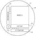
图1示出了本发明实施例1的摄像设备中要使用的图像传感器的结构。FIG. 1 shows the structure of an image sensor to be used in an image pickup apparatus of Embodiment 1 of the present invention.
图2示出了实施例1的图像传感器中的像素的结构。FIG. 2 shows the structure of pixels in the image sensor of Embodiment 1. In FIG.
图3示出了实施例1的图像传感器中的像素阵列。FIG. 3 shows a pixel array in the image sensor of Embodiment 1. FIG.
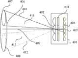
图4示出了实施例1的图像传感器上的图像形成。FIG. 4 shows image formation on the image sensor of Embodiment 1. FIG.
图5A~5D示出了实施例1的相位差检测方法中的像素行以及一对图像信号之间的关系。5A to 5D show the relationship between pixel rows and a pair of image signals in the phase difference detection method of Embodiment 1.
图6A和6B示出了实施例1的图像传感器中的焦点检测区域。6A and 6B show focus detection areas in the image sensor of Embodiment 1. FIG.
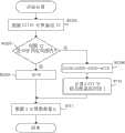
图7是示出实施例1的焦点检测计算的流程图。FIG. 7 is a flowchart showing focus detection calculation of Embodiment 1. FIG.
图8A~8C示出了第二相关数据与焦点状态之间的关系。8A to 8C show the relationship between the second correlation data and the focus state.
图9A和9B示出了本发明实施例2的图像传感器中的焦点检测区域。9A and 9B show focus detection areas in the image sensor of Embodiment 2 of the present invention.
图10示出了本发明实施例3的图像传感器中的焦点检测区域。FIG. 10 shows focus detection areas in the image sensor of Embodiment 3 of the present invention.
图11是示出实施例3中的焦点检测计算的流程图。FIG. 11 is a flowchart showing focus detection calculation in Embodiment 3. FIG.
图12是示出实施例3的变形例中的焦点检测计算的流程图。FIG. 12 is a flowchart showing focus detection calculation in a modified example of Embodiment 3. FIG.
图13示出了本发明实施例4的摄像设备的结构。FIG. 13 shows the configuration of an imaging apparatus according to Embodiment 4 of the present invention.
具体实施方式Detailed ways
以下将参考附图来说明本发明的典型实施例。Exemplary embodiments of the present invention will be described below with reference to the accompanying drawings.
实施例1Example 1
图1示出了作为本发明第一实施例(实施例1)的摄像设备中要使用的图像传感器(摄像元件)的结构。图像传感器100设置有由作为第一方向的水平方向和作为与第一方向垂直的第二方向的垂直方向上所配置的多个像素构成的矩阵状像素阵列101。FIG. 1 shows the structure of an image sensor (image pickup element) to be used in an image pickup apparatus as a first embodiment (Embodiment 1) of the present invention. The
下文中,将水平方向上呈直线状排列的像素组称为“像素行”,并将垂直方向上呈直线状排列的像素组称为“像素列”。像素阵列101包括多个像素行,其中这些像素行各自包括水平方向上排列的多个像素,并且像素行被配置在垂直方向上。换句话说,像素阵列101包括多个像素列,其中这些像素列各自包括垂直方向上排列的多个像素,并且像素列被配置在水平方向上。Hereinafter, pixel groups arranged linearly in the horizontal direction are referred to as "pixel rows", and pixel groups arranged linearly in the vertical direction are referred to as "pixel columns". The
图像传感器100包括用于选择垂直方向上配置的像素行其中之一的垂直选择电路102以及用于选择水平方向上配置的像素列其中之一的水平选择电路104。此外,图像传感器100包括:读取电路103,用于读取来自垂直选择电路102从像素阵列101的像素行所选择出的像素行的像素的信号(像素信号);以及串行接口(SI)105,用于从设备的外部设置各电路的一个工作模式等。对于各像素列,读取电路103包括增益放大器、A/D转换器、以及用于存储像素信号的存储器等。尽管未示出,但图像传感器100还包括:时序发生器,用于将定时信号供给至垂直选择电路102、水平选择电路104和读取电路103;以及控制器,用于控制像素信号的读取。The
在由此构成的图像传感器100中,垂直选择电路102顺次选择多个像素行中的一个像素行,并且读取电路103读取作为所选择的像素行所包括的像素的输出的像素信号。水平选择电路104在各像素列中顺次选择读取电路103读取的像素信号。In the thus constituted
图2示出了图像传感器100中的一个像素的结构。像素201具有一个微透镜202以及两个光电二极管(以下简称为“PD”)203和204。尽管未示出,但像素201还包括用于将来自PD的信号读取至读取电路103的像素放大器、用于选择像素的选择开关、以及用于对来自PD的信号进行复位的复位开关等。对通过使用来自PD 203和204的像素信号所分别产生的一对信号之间的相位差进行计算,这使得能够进行相位差检测方法的焦点检测。FIG. 2 shows the structure of one pixel in the
图3是像素阵列101的一部分的放大图。通过对各自如图2所示的像素进行配置以形成二维阵列来构成像素阵列101,这使得能够产生二维图像。附图标记301、302、303和304表示像素。附图标记301L、302L、303L和304L表示各自与图2所示的PD 203相对应的PD,而附图标记301R、302R、303R和304R表示与图2所示的PD 204相对应的PD。附图标记305表示一个像素行。FIG. 3 is an enlarged view of a portion of the
以下将参考图4来说明具有图3所示的像素阵列101的图像传感器100的光接收。图4示出了穿过摄像光学系统的出射光瞳406的光束入射到图像传感器100的状态。将摄像光学系统(例如,照相机镜头)设置为与摄像设备(例如,照相机)一体化或可更换。附图标记401表示像素阵列的截面。附图标记402表示与图2所示的微透镜202相对应的微透镜,并且附图标记403表示滤色器。附图标记404和405表示与图2所示的PD相对应的光电二极管。Light reception of the
在本说明书中,将穿过出射光瞳并入射到具有微透镜402的像素的光束的中心定义为光轴409。来自出射光瞳的光束以光束中心位于光轴409的方式入射到图像传感器100。附图标记407和408示出了摄像光学系统的出射光瞳的相互不同区域(以下称为“光瞳区域”)。穿过光瞳区域407的光束的最外周光线由附图标记410和411表示,并且穿过光瞳区域408的光束的最外周光线由附图标记412和413表示。In this specification, the center of the light beam passing through the exit pupil and incident on the pixel with the
由图4可以理解,在穿过出射光瞳的光束中,相对于光轴409位于上侧的光束入射到PD 405,并且相对于光轴409位于下侧的光束入射到PD 404。因而,PD 404和405接收穿过相互不同的光瞳区域的一对光束(即,由这对光束所形成的一对被摄体图像)。As can be understood from FIG. 4 , among the light beams passing through the exit pupil, the light beams located on the upper side with respect to the
尽管图2和4示出了针对一个微透镜设置两个PD的像素结构,但也可以采用如下的另一结构,其中在该另一结构中,一个像素设置有中心相对于该像素的光轴向着一侧偏移的一个PD,并且一个相邻像素设置有中心相对于该像素的光轴向着另一侧偏移的一个PD。将这两个像素用作一对像素以根据来自这对像素的输出(像素信号)产生一对图像信号,这使得能够进行图像传感器相位差检测方法的焦点检测。Although FIGS. 2 and 4 show a pixel structure in which two PDs are provided for one microlens, another structure may be employed in which one pixel is provided with a center relative to the optical axis of the pixel. One PD is shifted toward one side, and an adjacent pixel is provided with one PD whose center is shifted toward the other side with respect to the optical axis of the pixel. Using these two pixels as a pair of pixels to generate a pair of image signals based on outputs (pixel signals) from the pair of pixels enables focus detection of the image sensor phase difference detection method.
此外,还可采用如下结构:遮光层遮挡入射到微透镜的一侧的光束以达到与使PD的中心偏移相同的效果。因而,图像传感器仅需具有如下结构:一个像素或一对像素能够接收来自相互不同的光瞳区域的光束并且二维配置这些像素。In addition, a structure may also be employed in which the light-shielding layer shields light beams incident on one side of the microlens to achieve the same effect as shifting the center of the PD. Thus, the image sensor only needs to have a structure in which one pixel or a pair of pixels can receive light beams from mutually different pupil regions and the pixels are two-dimensionally arranged.
接下来将参考图5A~5D来说明焦点检测。本实施例在图像传感器100(像素阵列101)的一部分中,设置作为将各自在水平方向上延伸的多个像素行配置在垂直方向上的像素区域的焦点检测区域。此外,本实施例使得焦点检测区域中的各像素所包括的两个PD对来自相互不同的光瞳区域的一对光束所形成的一对被摄体图像(以下也称为“两个图像”)进行光电转换。Next, focus detection will be described with reference to FIGS. 5A to 5D . In this embodiment, in a part of the image sensor 100 (pixel array 101 ), a focus detection area is provided as a pixel area in which a plurality of pixel rows each extending in the horizontal direction are arranged in the vertical direction. In addition, the present embodiment makes a pair of subject images (hereinafter also referred to as "two images") formed by two PDs included in each pixel in the focus detection area pair a pair of light beams from mutually different pupil areas. ) for photoelectric conversion.
可以将各像素行视为包括用于对两个图像进行光电转换的两个PD行。在以下说明中,在焦点检测时将各PD作为像素进行处理,并且将两个PD行的其中一个以及另一个称为“A行像素”和“B行像素”。Each pixel row can be regarded as including two PD rows for photoelectric conversion of two images. In the following description, each PD is handled as a pixel at the time of focus detection, and one and the other of the two PD rows are referred to as "A row pixel" and "B row pixel".
图5A示出了焦点检测区域的一个像素行所包括的A行像素和B行像素。图5B~5D示出了对焦状态(图5B)、前焦点状态(图5C)和后焦点状态(图5D)的一对图像信号。FIG. 5A shows A row of pixels and B row of pixels included in one pixel row of the focus detection area. 5B to 5D show a pair of image signals in the in-focus state (FIG. 5B), the front focus state (FIG. 5C) and the back focus state (FIG. 5D).
在图3所示的像素行305中,像素(PD)301L、302L、303L和304L各自与A行像素相对应,并且像素(PD)301R、302R、303R和304R各自与B行像素相对应。In
利用来自A行像素和B行像素的输出所产生的一对图像信号之间的距离根据摄像光学系统的上述焦点状态(对焦状态、前焦点状态和后焦点状态)而改变。当摄像光学系统的焦点状态为前焦点状态或后焦点状态时,移动调焦透镜以使得一对图像信号之间的距离与对焦状态下的距离一致。换句话说,可以根据与摄像光学系统的散焦量相对应的两个图像的相对偏移量(即,相位差,以下称为“图像偏移量”)来计算调焦透镜的移动量。The distance between a pair of image signals generated using outputs from the pixels of the A row and the B row varies according to the above-mentioned focus states (focus state, front focus state, and rear focus state) of the imaging optical system. When the focus state of the imaging optical system is the front focus state or the rear focus state, the focus lens is moved so that the distance between a pair of image signals is consistent with the distance in the focus state. In other words, the movement amount of the focus lens can be calculated from the relative shift amount (ie, phase difference, hereinafter referred to as "image shift amount") of two images corresponding to the defocus amount of the imaging optical system.
接下来将参考图6A、6B和7来说明图像偏移量的计算方法。图6A和6B示出了图像传感器100上的焦点检测区域。图6A所示的区域中心为点601的焦点检测区域602包括X(水平)方向上从p列到q列的像素列以及Y(垂直)方向上从r行到s行的像素行。可以使该焦点检测区域602在-Imax和+Imax之间移位,这使得可以进行焦点检测的实质区域变成包括移位量的区域603(-Imax~+Imax)。Next, the calculation method of the image shift amount will be described with reference to FIGS. 6A , 6B, and 7 . 6A and 6B illustrate focus detection areas on the
图6B示出了与图6A所示的焦点检测区域603不同的焦点检测区域。如图6B所示,对焦点检测区域的移动使得能够在图像传感器100中(换句话说,在摄像框中)的任意区域内进行焦点检测。FIG. 6B shows a focus detection area different from the
图7的流程图示出了根据图6A和6B所示的焦点检测区域中所获得的一对图像信号来计算与调焦透镜的移动量相对应的散焦量的焦点检测计算(焦点检测方法)的处理。该计算是设置在摄像设备内的计算部根据计算机程序而进行的。7 is a flowchart showing focus detection calculation (focus detection method) for calculating a defocus amount corresponding to the movement amount of the focus lens from a pair of image signals obtained in the focus detection area shown in FIGS. 6A and 6B. ) processing. This calculation is performed by a calculation unit provided in the imaging device according to a computer program.
在步骤S701,已开始焦点检测计算的计算部选择第一像素行(Y=r)。接下来,在步骤S702,计算部设置Iy=-Imax。由于Y在这里为r,因而计算部计算r行的A行像素和B行像素的图像偏移量。在以下说明中,将A行像素上所形成的被摄体图像以及通过对该被摄体图像进行光电转换所获得的图像信号分别称为“A图像”和“A图像信号”,并且将B行像素上所形成的被摄体图像以及通过对该被摄体图像进行光电转换所获得的图像信号分别称为“B图像”和“B图像信号”。In step S701, the calculation section that has started focus detection calculation selects the first pixel row (Y=r). Next, in step S702, the calculation section sets Iy=-Imax. Since Y is r here, the calculation unit calculates the image shift amount of pixels in row A and row B in r rows. In the following description, the subject image formed on the A row of pixels and the image signal obtained by photoelectrically converting the subject image are referred to as "A image" and "A image signal", respectively, and B An object image formed on a row of pixels and an image signal obtained by photoelectrically converting the object image are referred to as a "B image" and a "B image signal", respectively.
接下来,在步骤S703,计算部使B图像信号移位与Iy像素相对应的移位量。接下来,在步骤S704,计算部利用以下表达式(1)来计算A图像信号与移位后的B图像信号之间的相关值。Next, in step S703, the calculation section shifts the B image signal by the shift amount corresponding to the Iy pixel. Next, in step S704, the calculation section calculates a correlation value between the A image signal and the shifted B image signal using the following expression (1).
其中,Ax和Bx分别表示来自特定像素行的A行像素和B行像素中坐标为x的像素的输出(像素值)。由以上表达式(1)可以理解,将相关值C(Iy)表示为相对移位了与Iy像素相对应的移位量的A图像信号和B图像信号之间的差的绝对值的总和。Among them, Ax and Bx represent the output (pixel value) of the pixel whose coordinate is x from among the pixels of row A and row B of a specific pixel row, respectively. As can be understood from the above expression (1), the correlation value C(Iy) is expressed as the sum of the absolute values of the differences between the A image signal and the B image signal relatively shifted by the shift amount corresponding to the Iy pixel.
还可以利用以下表达式(2)来计算相关值C(Iy)。The correlation value C(Iy) can also be calculated using the following expression (2).
计算部利用表达式(2),不仅使从B行像素所获得的B图像信号移位,还使从A行像素所获得的A图像信号在与B图像信号的移位方向相反的方向上移位,并且计算A图像信号和B图像信号之间的差的绝对值的总和。具体地,计算部使A图像信号移位与Iy像素相对应的移位量,并且使B图像信号移位与-Iy像素相对应的移位量。此外,在这种情况下,将相关值C(Iy)表示为相对移位后的A图像信号和B图像信号之间的差的绝对值的总和。Using expression (2), the calculation section not only shifts the B image signal obtained from the B row of pixels, but also shifts the A image signal obtained from the A row of pixels in a direction opposite to the shift direction of the B image signal. bits, and calculate the sum of the absolute values of the differences between the A image signal and the B image signal. Specifically, the calculation section shifts the A image signal by a shift amount corresponding to Iy pixels, and shifts the B image signal by a shift amount corresponding to −Iy pixels. Also, in this case, the correlation value C(Iy) is represented as the sum of the absolute values of the differences between the A image signal and the B image signal after the relative shift.
此外,可以利用以下表达式(3)、即通过计算A图像信号和移位了与Iy像素相对应的移位量的B图像信号(换句话说,相对移位后的A图像信号和B图像信号)中较大的图像信号的像素值的总和,来计算相关值C(Iy)。Furthermore, the following expression (3) can be used, that is, by calculating the A image signal and the B image signal shifted by the shift amount corresponding to 1y pixels (in other words, the relative shifted A image signal and B image signal) to calculate the correlation value C(Iy) by the sum of the pixel values of the larger image signal.
在以上表达式(3)中,max(A,B)表示选择A和B中较大的那个。此外,尽管没有给出表达式,但也可以通过选择A和B中较小的那个来计算相关值。因而,可以通过任意计算方法来计算该相关值。In the above expression (3), max(A, B) indicates that the larger of A and B is selected. Also, although no expression is given, the correlation value can also be calculated by selecting the smaller of A and B. Thus, the correlation value can be calculated by any calculation method.
接下来,在步骤S705,计算部将Iy+1代入Iy,换句话说,计算部使B图像信号移位Iy+1的像素数量。然后,在步骤S 706,计算部判断Iy是否达到Imax。如果Iy达到Imax,则计算部进入步骤S707。如果Iy小于Imax,则计算部重复步骤S703、S704和S705的处理。当进行步骤S707的处理时,计算第一相关数据C(Iy),其中该第一相关数据C(Iy)是直到Iy在一个像素行中从-Imax增加到Imax为止所移位的B图像信号的各移位位置(Iy)处的相关值的集合。获得第一相关数据,作为表示一个像素行中的与移位量(或移位位置)相对应的相关值的变化的波形数据。Next, in step S705, the calculation section substitutes Iy+1 into Iy, in other words, the calculation section shifts the B image signal by the number of pixels of Iy+1. Then, in step S706, the calculation unit judges whether Iy reaches Imax. If Iy reaches Imax, the calculation unit proceeds to step S707. If Iy is smaller than Imax, the calculation section repeats the processing of steps S703, S704, and S705. When the process of step S707 is performed, first correlation data C(Iy) which is a B image signal shifted until Iy increases from -Imax to Imax in one pixel row is calculated. A collection of correlation values at each shift position (Iy) of . The first correlation data is obtained as waveform data representing changes in correlation values corresponding to shift amounts (or shift positions) in one pixel row.
在步骤S707,计算部将C(Iy)+C(I)代入C(I)。此外,在步骤S708,计算部将Y+1代入Y。然后,在步骤S709,计算部判断Y是否达到s。如果Y达到s,则计算部进入步骤S710。如果Y小于s,则计算部返回到步骤S702。因而,计算部将r~s行的各像素行中在Y达到s之前所计算出的第一相关数据C(Iy)相加,从而获取第二相关数据C(I),其中该第二相关数据C(I)是焦点检测区域中所有像素行(r~s行)的相关数据。In step S707, the calculation unit substitutes C(Iy)+C(I) into C(I). In addition, in step S708, the calculation unit substitutes Y+1 into Y. Then, in step S709, the calculation unit judges whether or not Y has reached s. If Y reaches s, the calculation unit proceeds to step S710. If Y is smaller than s, the calculation unit returns to step S702. Therefore, the calculation unit adds the first correlation data C(Iy) calculated before Y reaches s in each pixel row of r~s rows, thereby obtaining the second correlation data C(I), wherein the second correlation Data C(I) is related data of all pixel rows (r~s rows) in the focus detection area.
在步骤S710,计算部求取第二相关数据C(I)表示最高相关性时的I。以下将参考图8A~8C来说明最高相关性。在图8A~8C中,第二相关数据C(I)表示相对移位了移位量I的A图像信号和B图像信号之间的相关值。当计算表达式(1)和(2)所示的作为像素信号的差的绝对值的总和的相关值时,第二相关数据C(I)的值最低时的I是相关性最高时的I。In step S710, the calculation unit obtains I when the second correlation data C(I) shows the highest correlation. The highest correlation will be described below with reference to FIGS. 8A to 8C . In FIGS. 8A to 8C , the second correlation data C(I) represents a correlation value between the A image signal and the B image signal that are relatively shifted by the shift amount I. When calculating the correlation value shown in Expressions (1) and (2) as the sum of the absolute values of the differences of the pixel signals, I when the value of the second correlation data C(I) is the lowest is I when the correlation is the highest .
在图8A所示的对焦状态中,第二相关数据C(I)表示最高相关性、即第二相关数据C(I)的值最低时的I是0。另一方面,在图8B所示的前焦点状态和图8C所示的后焦点状态中,第二相关数据C(I)表示最高相关性时的I是在其散焦方向上相对于0存在移位的I。该移位量I相当于作为相位差的图像偏移量。因此,计算部求取相关性最高时的I以计算r~s行的A行像素和B行像素的图像偏移量。In the focused state shown in FIG. 8A , the second correlation data C(I) indicates the highest correlation, that is, I is 0 when the value of the second correlation data C(I) is the lowest. On the other hand, in the front focus state shown in FIG. 8B and the back focus state shown in FIG. 8C , the second correlation data C(I) indicates that I when the highest correlation exists relative to 0 in its defocus direction Shifted I. This shift amount I corresponds to an image shift amount as a phase difference. Therefore, the calculation unit obtains I when the correlation is the highest to calculate the image shift amount of the pixels of the A row and the B row of the r~s rows.
接下来,在步骤S711,计算部将图像偏移量(移位量I)转换成摄像光学系统的散焦量L,然后结束焦点检测计算。之后,尽管未示出,但计算部基于散焦量L计算镜头移动量,以使调焦透镜移动所计算出的镜头移动量,从而获得对焦状态。Next, in step S711, the calculation section converts the image shift amount (shift amount I) into the defocus amount L of the imaging optical system, and then ends the focus detection calculation. After that, although not shown, the calculation section calculates a lens shift amount based on the defocus amount L to move the focus lens by the calculated lens shift amount, thereby obtaining an in-focus state.
如上所述,本实施例针对焦点检测区域中的各像素行计算第一相关数据,并且通过将针对焦点检测区域中的所有像素行所计算出的第一相关数据相加来产生第二相关数据。因而,本实施例仅需使根据第二相关数据计算相关性最高时的图像偏移量的处理进行一次,从而能够减少焦点检测计算所需的时间。As described above, the present embodiment calculates first correlation data for each pixel row in the focus detection area, and generates second correlation data by adding the first correlation data calculated for all pixel rows in the focus detection area . Therefore, the present embodiment only needs to perform the process of calculating the image shift amount when the correlation is the highest based on the second correlation data once, so that the time required for focus detection calculation can be reduced.
图2和3所示的各像素(包括两个PD的像素)不仅用于焦点检测,也用于产生记录/显示用的静止图像和运动图像(帧图像)。具体地,用于从图像传感器100分别读取来自图2所示的PD 203和204的像素信号并将这些像素信号相加的处理使得能够产生摄像用的一个像素的像素信号,并且能够利用该摄像用的像素信号产生图像。The pixels shown in FIGS. 2 and 3 (pixels including two PDs) are used not only for focus detection but also for generating still images and moving images (frame images) for recording/display. Specifically, processing for respectively reading pixel signals from the
实施例2Example 2
接下来将参考图9A和9B来说明本发明的第二实施例(实施例2)。图9A和图9B示出了如下内容:要根据焦点检测区域602和最大移位量Imax而确定的焦点检测区域603的实质大小可以根据摄像条件来改变,其中焦点检测区域602包括X(水平)方向上的像素列p~q和Y(垂直)方向上的像素行r~s。Next, a second embodiment (Embodiment 2) of the present invention will be described with reference to FIGS. 9A and 9B. 9A and 9B show that the substantial size of the
将图9B所示的焦点检测区域602和603在水平方向和垂直方向上设置得窄于图9A所示的焦点检测区域602和603。焦点检测区域的大小的改变是为了应对以下情况:A图像和B图像的图像偏移量或者A图像和B图像的大小根据诸如摄像光学系统的焦点状态和F值等的摄像条件中至少之一而改变。The
例如,由于A图像和B图像的图像偏移量及其大小在摄像条件是F值较小的条件以及焦点状态为极大失焦状态的情况下都较大,因而如图9A所示,将焦点检测区域602和603设置得较大。另一方面,由于A图像和B图像的图像偏移量及其大小在摄像条件是F值较大的条件以及焦点状态并非极大失焦状态的情况下都较小,因而如图9B所示,将焦点检测区域602和603设置得较小。For example, since the image shift amount and size of the A image and the B image are large when the imaging condition is a small F value and the focus state is a state of extreme defocus, as shown in FIG. 9A, the The focus
期望每次在一张静止图像的摄像以及在运动图像的1帧的摄像时进行焦点检测区域的大小的改变。此外,期望响应于诸如F值等的摄像条件的改变或要拍摄的被摄体的移动来进行焦点检测区域的大小的改变。It is desirable to change the size of the focus detection area each time one still image is captured and one frame of a moving image is captured. Furthermore, it is desirable to perform a change in the size of the focus detection area in response to a change in imaging conditions such as an F value or movement of a subject to be photographed.
实施例3Example 3
接下来将参考图10来说明本发明的第三实施例(实施例3)。实施例2说明了以下情况:期望每次在一张静止图像的摄像以及在运动图像的一帧的摄像时在水平方向和垂直方向上进行焦点检测区域的大小的改变。然而,在排列有像素行的垂直方向上,焦点检测区域的大小可以在不经由摄像的情况下(即,在一次的静止图像摄像期间以及在1帧图像的摄像期间)根据各种摄像条件而改变。Next, a third embodiment (Embodiment 3) of the present invention will be described with reference to FIG. 10 . Embodiment 2 explained the case where it is desirable to change the size of the focus detection area in the horizontal direction and the vertical direction at each imaging of one still image and imaging of one frame of a moving image. However, in the vertical direction in which pixel rows are arranged, the size of the focus detection area can be changed according to various imaging conditions without via imaging (that is, during one still image imaging and during imaging of 1-frame image). Change.
图10示出了将图像传感器100内所设置的实质焦点检测区域603垂直地分割为多个区域(以下各自称为“分割区域”)1001、1002和1003。分割区域1001、1002和1003各自包括多个像素行和多个像素列。本实施例的计算部根据各分割区域1001、1002和1003来计算作为实施例1所述的第二相关数据C(I)的C1(I)、C2(I)和C3(I),然后根据C1(I)、C2(I)和C3(I)来计算散焦量L。FIG. 10 shows that a substantial
以下将参考图11的流程图来说明本实施例中的焦点检测计算(焦点检测方法)的处理。设置在摄像设备中的计算部根据计算机程序来进行该焦点检测计算。The processing of the focus detection calculation (focus detection method) in the present embodiment will be described below with reference to the flowchart of FIG. 11 . A calculation section provided in the imaging device performs this focus detection calculation according to a computer program.
在步骤S1101,已开始焦点检测计算的计算部将作为赋予至分割区域1001、1002和1003的编号的n设为1,以选择第一分割区域1001。In step S1101 , the calculation section that has started the focus detection calculation sets n, which is a number assigned to the divided
接下来,在步骤S701~S709,计算部进行与实施例1相同的处理,以计算第一分割区域1001中的各像素行的第一相关数据C1(Iy)。然后,计算部将针对分割区域1001中的所有像素行所计算出的第一相关数据C1(Iy)相加,以获取第二相关数据C1(I)。在步骤S707,计算部将Cn(Iy)+Cn(I)代入Cn(I)。Next, in steps S701 to S709 , the calculation unit performs the same processing as in the first embodiment to calculate the first correlation data C1 (Iy) of each pixel row in the first divided
在步骤S 709,计算部判断Y是否达到表示第n个分割区域的像素行中的s行的s(n)。将Y达到s(n)之前针对所有像素行而计算出的第一相关数据Cn(Iy)相加,这使得能够获取第n个分割区域中的第二相关数据Cn(I)。如果Y达到s(n),则计算部进入步骤S1102。如果Y小于s(n),则计算部返回到步骤S702。In step S709, the calculation unit judges whether Y has reached s(n) representing s rows among the pixel rows of the n-th divided region. Adding the first correlation data Cn(Iy) calculated for all the pixel rows before Y reaches s(n) makes it possible to acquire the second correlation data Cn(I) in the n-th divided area. If Y reaches s(n), the calculation unit proceeds to step S1102. If Y is smaller than s(n), the calculation unit returns to step S702.
在步骤S1102,计算部将n+1代入n。此外,在步骤S1103,计算部判断n是否达到3。如果n小于3,则计算部选择下一分割区域,并进行步骤S701~S709的处理,以获得针对下一分割区域的第二相关数据(C2(I)或C3(I))。当在步骤S1103中n由此达到3时,计算部进入步骤S1104。In step S1102, the calculation unit substitutes n+1 into n. Furthermore, in step S1103, the calculation unit judges whether or not n has reached 3. If n is less than 3, the calculation unit selects the next segmented area, and performs the processing of steps S701 to S709 to obtain the second correlation data (C2(I) or C3(I)) for the next segmented area. When n thus reaches 3 in step S1103, the calculation section proceeds to step S1104.
在步骤S1104,计算部根据作为三个分割区域1001、1002和1003的第二相关数据Cn(I)的C1(I)、C2(I)和C3(I)来产生最佳第二相关数据(以下称为“最佳相关数据”)C(I)。具体地,计算部在F值较小时通过将C1(I)、C2(I)和C3(I)相加来产生最佳相关数据Cn(I),而另一方面,在F值较大时仅利用C2(I)来产生最佳相关数据Cn(I)。In step S1104, the calculation section generates optimum second correlation data ( Hereinafter referred to as "best correlation data") C(I). Specifically, the calculation section generates optimum correlation data Cn(I) by adding C1(I), C2(I) and C3(I) when the F value is small, and on the other hand, when the F value is large, Only C2(I) is utilized to generate the best correlation data Cn(I).
接下来,在步骤S710和S711,如实施例1所述,计算部根据最佳相关数据Cn(I)来计算相关性最高时的移位量(图像偏移量)I,并且根据该移位量I来计算散焦量L。Next, in steps S710 and S711, as described in Embodiment 1, the calculation section calculates the shift amount (image shift amount) I when the correlation is the highest based on the optimal correlation data Cn(I), and based on the shift The amount I is used to calculate the defocus amount L.
以下将参考图12的流程图来说明根据针对分割区域1001、1002和1003所计算出的第二相关数据C1(I)、C2(I)和C3(I)来计算散焦量L的另一方法。下文将说明图11中的步骤S1104及之后步骤的处理的替代处理。Another method of calculating the defocus amount L based on the second correlation data C1(I), C2(I) and C3(I) calculated for the divided
在通过直到步骤S1103的处理计算出第二相关数据C1(I)、C2(I)和C3(I)之后,计算部进入步骤S1201。在步骤S1201,计算部根据针对分割区域1002所计算出的第二相关数据C2(I)来计算相关性最高时的移位量I2(即,作为特定分割区域的分割区域1002中的图像偏移量)。利用与实施例1中步骤S710所述的方法相同的方法来计算移位量I2。After calculating the second correlation data C1(I), C2(I), and C3(I) through the processing up to step S1103, the calculation section proceeds to step S1201. In step S1201, the calculation section calculates the shift amount I2 (that is, the image shift in the divided
接下来,在步骤S1202,计算部判断移位量I2是否在预定范围内。例如,当移位量较小时,F值较大或散焦量较小。如果移位量I2较小且在预定范围内,则计算部进入步骤S1203以将I2代入相关性最高时的I。之后,计算部进入步骤S711以根据该I来计算散焦量L。Next, in step S1202, the calculating section judges whether or not the shift amount I2 is within a predetermined range. For example, when the amount of shift is small, the F value is large or the amount of defocus is small. If the shift amount I2 is small and within the predetermined range, the calculation section proceeds to step S1203 to substitute I2 for I at the time of the highest correlation. After that, the calculation section proceeds to step S711 to calculate the defocus amount L from this I.
另一方面,当移位量较大时,F值较小或散焦量较大。如果移位量I2较大且没有在预定范围内,则计算部进入步骤S1204以将C1(I)+C2(I)+C3(I)代入C(I)。在这种情况下,期望设置较大的焦点检测区域。因此,在步骤S1204,计算部将第二相关数据C1(I)、C2(I)和C3(I)相加以产生最佳相关数据C(I)。On the other hand, when the amount of shift is large, the F value is small or the amount of defocus is large. If the shift amount I2 is large and not within the predetermined range, the calculating section proceeds to step S1204 to substitute C1(I)+C2(I)+C3(I) into C(I). In this case, it is desirable to set a larger focus detection area. Therefore, in step S1204, the calculation section adds the second correlation data C1(I), C2(I) and C3(I) to generate the optimal correlation data C(I).
然后,计算部进入步骤S710和S711,以根据最佳相关数据Cn(I)来计算相关性最高时的移位量(图像偏移量)I,并且根据该移位量I来计算散焦量L。Then, the calculation section proceeds to steps S710 and S711 to calculate the shift amount (image shift amount) I when the correlation is the highest from the best correlation data Cn(I), and calculate the defocus amount from the shift amount I L.
如上所述,首先,本实施例根据针对分割区域1002所产生的第二相关数据来计算图像偏移量。然后,本实施例判断作为用于计算散焦量的第二相关数据,是使用仅针对分割区域1002所产生的第二相关数据还是使用分别针对分割区域1001、1002和1003所产生的第二相关数据。As described above, first, the present embodiment calculates the image offset according to the second correlation data generated for the divided
因而,根据图像偏移量(移位量I),本实施例使得能够在一次的静止图像摄像期间以及在1帧图像的摄像期间在排列有像素行的方向上改变焦点检测区域的大小。此外,本实施例针对通过分割焦点检测区域所设置的分割区域中的各像素行来计算第一相关数据,并且将针对该分割区域中的所有像素行的第一相关数据相加,以产生针对该分割区域的第二相关数据。然后,本实施例利用第二相关数据来计算相关性最高时的图像偏移量(移位量I)。因此,本实施例仅需使图像偏移量(移位量I)的计算进行一次,从而能够减少焦点检测计算所需的时间。Thus, according to the image shift amount (shift amount I), the present embodiment enables changing the size of the focus detection area in the direction in which pixel rows are arranged during one still image imaging and during imaging of 1-frame image. In addition, the present embodiment calculates first correlation data for each pixel row in a divided region set by dividing the focus detection region, and adds the first correlation data for all pixel rows in the divided region to generate The second related data of the segmented area. Then, this embodiment uses the second correlation data to calculate the image shift amount (shift amount I) when the correlation is the highest. Therefore, the present embodiment only needs to perform the calculation of the image shift amount (shift amount I) once, so that the time required for focus detection calculation can be reduced.
尽管实施例1~3各自说明了针对各像素行产生第一相关数据并且将针对所有像素行所产生的第一相关数据相加以产生第二相关数据的情况,但也可以通过将针对各像素列所产生的第一相关数据相加以及将针对所有像素列所产生的第一相关数据相加来产生第二相关数据。此外,实施例3所述的焦点检测计算也能应用于如下情况:将焦点检测区域分割为排列有像素列的水平方向上的多个区域。Although Embodiments 1 to 3 each described the case of generating the first correlation data for each pixel row and adding the first correlation data generated for all pixel rows to generate the second correlation data, it is also possible to generate the second correlation data by adding the first correlation data for each pixel row The generated first correlation data is added and the generated first correlation data for all pixel columns is added to generate second correlation data. In addition, the focus detection calculation described in Embodiment 3 can also be applied to a case where the focus detection area is divided into a plurality of areas in the horizontal direction in which pixel columns are arranged.
实施例4Example 4
图13示出了作为设置有实施例1~3所述的计算部的(换句话说,进行焦点检测的)摄像设备的数字照相机。在图13中,附图标记1301表示用于使来自被摄体的光束形成被摄体图像的摄像镜头(摄像光学系统)。摄像镜头1301包括变倍透镜、调焦透镜和光圈。通过用于接收来自(下述)主控制/计算部1309的指示的镜头驱动器1302来驱动这些透镜和光圈。FIG. 13 shows a digital camera as an imaging apparatus provided with the calculating section described in Embodiments 1 to 3 (in other words, performing focus detection). In FIG. 13 ,
附图标记1303表示要由用于接收来自主控制/计算部1309的指示的快门驱动器1304进行驱动的机械快门。附图标记1305表示与实施例1~3中的图像传感器100相对应且用于对摄像镜头1301所形成的被摄体图像进行光电转换的图像传感器。
附图标记1306表示用于对来自图像传感器1305的输出信号进行各种处理的摄像信号处理器(信号产生部)。摄像信号处理器1306根据从图像传感器1305的焦点检测区域所包括的各像素行的像素所输出的像素信号,来产生一对图像信号。
附图标记1307表示用于将定时信号输出至图像传感器1305和摄像信号处理器1306的时序发生器。主控制/计算部1309控制整个照相机的操作并且用作实施例1~3所述的计算部。附图标记1313表示用于对被摄体进行测光的测光器。
附图标记1308表示用于临时存储摄像信号处理器1306所产生的图像的存储器。附图标记1310表示用于与诸如半导体存储器等的记录介质进行图像的记录和读取的记录介质接口。记录介质1311以能够拆卸的方式安装到照相机。附图标记1312表示用于显示各种信息和图像的显示部。
在由此配置的数字照相机中,主电源的接通使得开始向包括主控制/计算部1309的控制系统供给电力,并且开始向包括摄像信号处理器1306的摄像系统供给电力。In the digital camera thus configured, turning on of the main power supply starts power supply to the control system including the main control/
接下来,响应于用户对释放按钮(未示出)的操作,主控制/计算部1309利用摄像信号处理器1306针对图像传感器1305中的焦点检测区域的各像素行所产生的一对图像信号,来进行焦点检测以及散焦量的计算。然后,主控制/计算部1309基于计算结果来计算调焦透镜的移动量,并且通过镜头驱动器1302使调焦透镜移动计算出的移动量,从而获得对焦状态。Next, in response to the user's operation of a release button (not shown), the main control/
在确认了对焦状态之后,主控制/计算部1309开始摄像操作。主控制/计算部1309使得摄像信号处理器1306对来自图像传感器1305的输出信号进行图像处理并产生所拍摄图像(静止图像或运动图像)。主控制/计算部1309使记录介质接口1310将所拍摄图像写至记录介质1311。After confirming the in-focus state, the main control/
尽管已经参考典型实施例说明了本发明,但是应该理解,本发明不限于所公开的典型实施例。所附权利要求书的范围符合最宽的解释,以包含所有这类修改、等同结构和功能。While the present invention has been described with reference to exemplary embodiments, it is to be understood that the invention is not limited to the disclosed exemplary embodiments. The scope of the appended claims is to be accorded the broadest interpretation to encompass all such modifications and equivalent structures and functions.
Claims (5)
Translated fromChineseApplications Claiming Priority (2)
| Application Number | Priority Date | Filing Date | Title |
|---|---|---|---|
| JP2011210018AJP5907595B2 (en) | 2011-09-27 | 2011-09-27 | Imaging device |
| JP2011-210018 | 2011-09-27 |
Publications (2)
| Publication Number | Publication Date |
|---|---|
| CN103024264Atrue CN103024264A (en) | 2013-04-03 |
| CN103024264B CN103024264B (en) | 2016-08-17 |
Family
ID=47225298
Family Applications (1)
| Application Number | Title | Priority Date | Filing Date |
|---|---|---|---|
| CN201210369590.6AActiveCN103024264B (en) | 2011-09-27 | 2012-09-27 | Picture pick-up device and focus detecting method |
Country Status (5)
| Country | Link |
|---|---|
| US (2) | US9048152B2 (en) |
| JP (1) | JP5907595B2 (en) |
| CN (1) | CN103024264B (en) |
| DE (1) | DE102012217165B4 (en) |
| GB (1) | GB2497160B (en) |
Cited By (6)
| Publication number | Priority date | Publication date | Assignee | Title |
|---|---|---|---|---|
| CN105430256A (en)* | 2014-09-11 | 2016-03-23 | 佳能株式会社 | Camera device and method of controlling camera device |
| CN105934944A (en)* | 2013-11-26 | 2016-09-07 | 株式会社尼康 | Electronic equipment, imaging device, and imaging element |
| CN106210502A (en)* | 2014-06-24 | 2016-12-07 | 佳能株式会社 | Camera head, control device and control method |
| CN106412419A (en)* | 2015-07-31 | 2017-02-15 | 佳能株式会社 | Image capture apparatus and method for controlling the same |
| CN107249097A (en)* | 2013-04-10 | 2017-10-13 | 佳能株式会社 | Picture pick-up device and its control method |
| CN110636277A (en)* | 2018-06-21 | 2019-12-31 | 佳能株式会社 | Detection apparatus, detection method, and image pickup apparatus |
Families Citing this family (34)
| Publication number | Priority date | Publication date | Assignee | Title |
|---|---|---|---|---|
| JP5956782B2 (en)* | 2011-05-26 | 2016-07-27 | キヤノン株式会社 | Imaging device and imaging apparatus |
| JP5845023B2 (en) | 2011-08-08 | 2016-01-20 | キヤノン株式会社 | FOCUS DETECTION DEVICE, LENS DEVICE HAVING THE SAME, AND IMAGING DEVICE |
| JP5888914B2 (en)* | 2011-09-22 | 2016-03-22 | キヤノン株式会社 | Imaging apparatus and control method thereof |
| JP5907595B2 (en)* | 2011-09-27 | 2016-04-26 | キヤノン株式会社 | Imaging device |
| JP2014106476A (en)* | 2012-11-29 | 2014-06-09 | Canon Inc | Focus detection device, imaging device, imaging system, focus detection method, program and storage medium |
| JP5911445B2 (en)* | 2013-03-19 | 2016-04-27 | キヤノン株式会社 | Imaging apparatus and control method thereof |
| JP6334847B2 (en)* | 2013-04-17 | 2018-05-30 | キヤノン株式会社 | FOCUS DETECTION DEVICE, FOCUS DETECTION METHOD AND PROGRAM, AND IMAGING DEVICE |
| JP6532119B2 (en)* | 2013-04-30 | 2019-06-19 | キヤノン株式会社 | Image pickup apparatus and control method thereof |
| JP6372983B2 (en) | 2013-09-02 | 2018-08-15 | キヤノン株式会社 | FOCUS DETECTION DEVICE, ITS CONTROL METHOD, AND IMAGING DEVICE |
| CN111479066B (en)* | 2013-09-26 | 2022-11-18 | 株式会社尼康 | Image pickup element and image pickup apparatus |
| JP2015102735A (en)* | 2013-11-26 | 2015-06-04 | 株式会社ニコン | Focus detection apparatus and imaging apparatus |
| JP6555863B2 (en) | 2013-12-25 | 2019-08-07 | キヤノン株式会社 | IMAGING DEVICE AND IMAGING DEVICE CONTROL METHOD |
| WO2015146229A1 (en)* | 2014-03-25 | 2015-10-01 | 富士フイルム株式会社 | Imaging device and focusing control method |
| JP6465562B2 (en) | 2014-04-30 | 2019-02-06 | キヤノン株式会社 | Imaging apparatus and imaging method |
| JP2015233270A (en)* | 2014-05-13 | 2015-12-24 | キヤノン株式会社 | Imaging apparatus and control method of the same |
| JP2015228466A (en)* | 2014-06-02 | 2015-12-17 | キヤノン株式会社 | Imaging apparatus and imaging system |
| JP6631002B2 (en)* | 2014-11-26 | 2020-01-15 | 株式会社ニコン | Imaging device |
| JP6506560B2 (en)* | 2015-01-20 | 2019-04-24 | キヤノン株式会社 | Focus control device and method therefor, program, storage medium |
| US9826142B2 (en) | 2015-03-17 | 2017-11-21 | Canon Kabushiki Kaisha | Image pickup apparatus and method of controlling image pickup apparatus |
| JP6557499B2 (en) | 2015-04-09 | 2019-08-07 | キヤノン株式会社 | FOCUS DETECTION DEVICE, ITS CONTROL METHOD, IMAGING DEVICE, PROGRAM, AND STORAGE MEDIUM |
| JP6444254B2 (en)* | 2015-04-23 | 2018-12-26 | キヤノン株式会社 | FOCUS DETECTION DEVICE, IMAGING DEVICE, FOCUS DETECTION METHOD, PROGRAM, AND STORAGE MEDIUM |
| JP6594048B2 (en)* | 2015-05-29 | 2019-10-23 | キヤノン株式会社 | Imaging apparatus and control method thereof |
| JP6639155B2 (en)* | 2015-08-28 | 2020-02-05 | キヤノン株式会社 | Image processing apparatus and image processing method |
| JP6685712B2 (en)* | 2015-12-14 | 2020-04-22 | キヤノン株式会社 | Image processing device, distance detection device, focus adjustment device, imaging device, image processing method and program |
| JP6532411B2 (en)* | 2016-01-14 | 2019-06-19 | キヤノン株式会社 | IMAGE PROCESSING DEVICE, IMAGING DEVICE, AND IMAGE PROCESSING PROGRAM |
| JP6744748B2 (en)* | 2016-04-06 | 2020-08-19 | キヤノン株式会社 | Solid-state imaging device and manufacturing method thereof |
| CN109073859B (en)* | 2016-04-07 | 2021-07-16 | 富士胶片株式会社 | Focus control device, lens device, imaging device, focus control method, focus control program |
| JP6762766B2 (en) | 2016-06-01 | 2020-09-30 | キヤノン株式会社 | Image sensor, image sensor, and image signal processing method |
| JP6765860B2 (en) | 2016-06-01 | 2020-10-07 | キヤノン株式会社 | Image sensor, image sensor, and image signal processing method |
| JP6881911B2 (en) | 2016-08-01 | 2021-06-02 | キヤノン株式会社 | Control device, image pickup device, control method, program, and storage medium |
| JP6858022B2 (en)* | 2017-01-20 | 2021-04-14 | キヤノン株式会社 | Focus detector, its control method and program, and imaging device |
| JP6460145B2 (en)* | 2017-04-20 | 2019-01-30 | 株式会社ニコン | Imaging device |
| JP7305418B2 (en)* | 2019-04-25 | 2023-07-10 | キヤノン株式会社 | Imaging device and image processing method |
| JP2023148577A (en)* | 2022-03-30 | 2023-10-13 | キヤノン株式会社 | Control unit, lens device, imaging apparatus, control method, and program |
Citations (6)
| Publication number | Priority date | Publication date | Assignee | Title |
|---|---|---|---|---|
| US20030123871A1 (en)* | 2001-12-07 | 2003-07-03 | Hideo Yoshida | Distance measuring apparatus |
| US20090256952A1 (en)* | 2008-04-11 | 2009-10-15 | Nikon Corporation | Correlation calculation method, correlation calculation device, focus detection device and image-capturing apparatus |
| US20090278966A1 (en)* | 2006-09-14 | 2009-11-12 | Nikon Corporation | Image sensor and imaging apparatus |
| CN101889231A (en)* | 2007-12-10 | 2010-11-17 | 佳能株式会社 | Image pickup apparatus and control method thereof |
| CN101918873A (en)* | 2008-02-13 | 2010-12-15 | 佳能株式会社 | Image forming apparatus |
| CN102197328A (en)* | 2008-09-24 | 2011-09-21 | 索尼公司 | Image pickup element and image pickup device |
Family Cites Families (16)
| Publication number | Priority date | Publication date | Assignee | Title |
|---|---|---|---|---|
| JPS592147B2 (en) | 1976-09-21 | 1984-01-17 | 松下電器産業株式会社 | photocell |
| JP3592147B2 (en) | 1998-08-20 | 2004-11-24 | キヤノン株式会社 | Solid-state imaging device |
| JP4007716B2 (en)* | 1999-04-20 | 2007-11-14 | オリンパス株式会社 | Imaging device |
| JP3774597B2 (en) | 1999-09-13 | 2006-05-17 | キヤノン株式会社 | Imaging device |
| JP2001250931A (en) | 2000-03-07 | 2001-09-14 | Canon Inc | Solid-state imaging device and imaging system using the same |
| JP2002314062A (en)* | 2001-04-18 | 2002-10-25 | Canon Inc | Solid-state imaging device and imaging system |
| JP2006178076A (en) | 2004-12-21 | 2006-07-06 | Olympus Corp | Focus detector for camera |
| JP5176483B2 (en)* | 2007-10-30 | 2013-04-03 | 株式会社ニコン | Image recognition device, image tracking device, and imaging device |
| JP5256711B2 (en)* | 2007-11-28 | 2013-08-07 | 株式会社ニコン | Imaging device and imaging apparatus |
| JP5169499B2 (en)* | 2008-06-02 | 2013-03-27 | 株式会社ニコン | Imaging device and imaging apparatus |
| JP5202289B2 (en)* | 2008-12-25 | 2013-06-05 | キヤノン株式会社 | Imaging device |
| JP5045801B2 (en)* | 2009-09-09 | 2012-10-10 | 株式会社ニコン | Focus detection device, photographing lens unit, imaging device, and camera system |
| JP2012043939A (en)* | 2010-08-18 | 2012-03-01 | Sony Corp | Imaging element and imaging apparatus |
| JP5493010B2 (en)* | 2010-11-30 | 2014-05-14 | 富士フイルム株式会社 | Imaging apparatus and focus position detection method thereof |
| CN103403599B (en) | 2011-03-31 | 2015-09-02 | 富士胶片株式会社 | Camera device and focus control method thereof |
| JP5907595B2 (en)* | 2011-09-27 | 2016-04-26 | キヤノン株式会社 | Imaging device |
- 2011
- 2011-09-27JPJP2011210018Apatent/JP5907595B2/enactiveActive
- 2012
- 2012-09-24USUS13/625,470patent/US9048152B2/ennot_activeExpired - Fee Related
- 2012-09-24DEDE102012217165.7Apatent/DE102012217165B4/enactiveActive
- 2012-09-27GBGB1217302.7Apatent/GB2497160B/enactiveActive
- 2012-09-27CNCN201210369590.6Apatent/CN103024264B/enactiveActive
- 2015
- 2015-04-17USUS14/689,729patent/US9538068B2/enactiveActive
Patent Citations (6)
| Publication number | Priority date | Publication date | Assignee | Title |
|---|---|---|---|---|
| US20030123871A1 (en)* | 2001-12-07 | 2003-07-03 | Hideo Yoshida | Distance measuring apparatus |
| US20090278966A1 (en)* | 2006-09-14 | 2009-11-12 | Nikon Corporation | Image sensor and imaging apparatus |
| CN101889231A (en)* | 2007-12-10 | 2010-11-17 | 佳能株式会社 | Image pickup apparatus and control method thereof |
| CN101918873A (en)* | 2008-02-13 | 2010-12-15 | 佳能株式会社 | Image forming apparatus |
| US20090256952A1 (en)* | 2008-04-11 | 2009-10-15 | Nikon Corporation | Correlation calculation method, correlation calculation device, focus detection device and image-capturing apparatus |
| CN102197328A (en)* | 2008-09-24 | 2011-09-21 | 索尼公司 | Image pickup element and image pickup device |
Cited By (13)
| Publication number | Priority date | Publication date | Assignee | Title |
|---|---|---|---|---|
| CN107249097A (en)* | 2013-04-10 | 2017-10-13 | 佳能株式会社 | Picture pick-up device and its control method |
| CN107249097B (en)* | 2013-04-10 | 2020-04-07 | 佳能株式会社 | Image pickup apparatus and control method thereof |
| CN105934944A (en)* | 2013-11-26 | 2016-09-07 | 株式会社尼康 | Electronic equipment, imaging device, and imaging element |
| CN106210502B (en)* | 2014-06-24 | 2019-03-29 | 佳能株式会社 | Photographic device, control device and control method |
| CN106210502A (en)* | 2014-06-24 | 2016-12-07 | 佳能株式会社 | Camera head, control device and control method |
| CN105430256B (en)* | 2014-09-11 | 2018-11-06 | 佳能株式会社 | The control method of picture pick-up device and picture pick-up device |
| CN105430256A (en)* | 2014-09-11 | 2016-03-23 | 佳能株式会社 | Camera device and method of controlling camera device |
| CN106412419A (en)* | 2015-07-31 | 2017-02-15 | 佳能株式会社 | Image capture apparatus and method for controlling the same |
| US10412330B2 (en) | 2015-07-31 | 2019-09-10 | Canon Kabushiki Kaisha | Image capture apparatus and method for controlling the same |
| CN106412419B (en)* | 2015-07-31 | 2020-11-10 | 佳能株式会社 | Image pickup apparatus and control method thereof |
| CN110636277A (en)* | 2018-06-21 | 2019-12-31 | 佳能株式会社 | Detection apparatus, detection method, and image pickup apparatus |
| US11140311B2 (en) | 2018-06-21 | 2021-10-05 | Canon Kabushiki Kaisha | Detecting apparatus and detecting method |
| CN110636277B (en)* | 2018-06-21 | 2022-08-16 | 佳能株式会社 | Detection apparatus, detection method, and image pickup apparatus |
Also Published As
| Publication number | Publication date |
|---|---|
| US9538068B2 (en) | 2017-01-03 |
| JP2013072906A (en) | 2013-04-22 |
| GB201217302D0 (en) | 2012-11-14 |
| DE102012217165A1 (en) | 2013-05-02 |
| DE102012217165B4 (en) | 2019-09-19 |
| US20150222811A1 (en) | 2015-08-06 |
| US20130076970A1 (en) | 2013-03-28 |
| CN103024264B (en) | 2016-08-17 |
| GB2497160B (en) | 2015-11-04 |
| JP5907595B2 (en) | 2016-04-26 |
| US9048152B2 (en) | 2015-06-02 |
| GB2497160A (en) | 2013-06-05 |
Similar Documents
| Publication | Publication Date | Title |
|---|---|---|
| CN103024264B (en) | Picture pick-up device and focus detecting method | |
| US9380202B2 (en) | Focus detection apparatus, image pickup apparatus, image pickup system, focus detection method, and non-transitory computer-readable storage medium | |
| CN102422196B (en) | Focus detection apparatus | |
| JP5895355B2 (en) | Imaging device | |
| US10009533B2 (en) | Image pickup apparatus and control method thereof with contrast focus evaluation | |
| US20140192237A1 (en) | Image processing apparatus, image processing method and program, and image pickup apparatus including image processing apparatus | |
| JP6066593B2 (en) | Imaging system and driving method of imaging system | |
| US9554054B2 (en) | Imaging apparatus and its control method and program | |
| JP5966636B2 (en) | Imaging device and imaging apparatus | |
| US9485406B2 (en) | Focus detection apparatus, focus detection method and program, and imaging apparatus | |
| US9625787B2 (en) | Focus detection apparatus, focus detection method and program, and imaging apparatus | |
| JP2015161906A (en) | Imaging apparatus | |
| US9451175B2 (en) | Imaging apparatus, information processing device, image pickup method, and non-transitory computer-readable storage medium storing a program therefor for obtaining light field information | |
| JP6476547B2 (en) | Focus detection device and imaging device | |
| JP2009251523A (en) | Correlation calculation method, correlation calculation device, focus detecting device and imaging apparatus | |
| JP6437049B2 (en) | FOCUS DETECTION DEVICE, IMAGING DEVICE, IMAGING SYSTEM, AND RANGING DEVICE | |
| JP6305454B2 (en) | Imaging device | |
| JP4642547B2 (en) | Focus detection device | |
| JP2015108672A (en) | Image capturing device and control method therefor | |
| JP5917205B2 (en) | Imaging device | |
| JP2017125965A (en) | Image processing apparatus, imaging apparatus, and image processing program | |
| JP6566072B2 (en) | Imaging device and imaging apparatus | |
| JP2019149608A (en) | Imaging apparatus and focus detection device | |
| JP2014095874A (en) | Image capturing device and control method therefor |
Legal Events
| Date | Code | Title | Description |
|---|---|---|---|
| C06 | Publication | ||
| PB01 | Publication | ||
| C10 | Entry into substantive examination | ||
| SE01 | Entry into force of request for substantive examination | ||
| C14 | Grant of patent or utility model | ||
| GR01 | Patent grant |