CN103022719A - Vehicle-borne STOM (satcom on the move) array antenna with gain increased by lightweight dielectric lens - Google Patents
Vehicle-borne STOM (satcom on the move) array antenna with gain increased by lightweight dielectric lensDownload PDFInfo
- Publication number
- CN103022719A CN103022719ACN2012105732632ACN201210573263ACN103022719ACN 103022719 ACN103022719 ACN 103022719ACN 2012105732632 ACN2012105732632 ACN 2012105732632ACN 201210573263 ACN201210573263 ACN 201210573263ACN 103022719 ACN103022719 ACN 103022719A
- Authority
- CN
- China
- Prior art keywords
- antenna
- dielectric
- polarization
- dielectric lens
- array antenna
- Prior art date
- Legal status (The legal status is an assumption and is not a legal conclusion. Google has not performed a legal analysis and makes no representation as to the accuracy of the status listed.)
- Pending
Links
- 230000010287polarizationEffects0.000claimsabstractdescription35
- 230000005540biological transmissionEffects0.000claimsdescription7
- 239000004033plasticSubstances0.000claimsdescription7
- 239000000463materialSubstances0.000claimsdescription6
- 239000002184metalSubstances0.000claimsdescription3
- 238000010295mobile communicationMethods0.000abstractdescription10
- 238000001746injection mouldingMethods0.000abstractdescription3
- 239000004743PolypropyleneSubstances0.000description5
- 238000004891communicationMethods0.000description4
- 238000010586diagramMethods0.000description3
- 230000005684electric fieldEffects0.000description2
- 230000005855radiationEffects0.000description2
- 230000009286beneficial effectEffects0.000description1
- 238000000034methodMethods0.000description1
- -1polypropylenePolymers0.000description1
- 229920001155polypropylenePolymers0.000description1
- 238000000926separation methodMethods0.000description1
Images


Landscapes
- Aerials With Secondary Devices (AREA)
- Variable-Direction Aerials And Aerial Arrays (AREA)
Abstract
Translated fromChinese
Description
Translated fromChinese技术领域technical field
本发明涉及车载动中通阵列,具体涉及一种使用轻质介质透镜提高增益的车载动中通阵列天线。The invention relates to a vehicle-mounted mobile communication array, in particular to a vehicle-mounted mobile communication array antenna which uses a light dielectric lens to increase gain.
背景技术Background technique
动中通系统是“移动中的卫星地面站通信系统”的简称,通过动中通系统,车辆、轮船以及飞机等可以在运动中与卫星进行实时通信,不间断地发送数据、图像等多媒体信息,可以满足各种军用民用应急通信和移动条件下的通信需求。由于动中通系统是与卫星进行通信,所以它需要高增益、高指向性的天线,另外,由于动中通系统是安装在移动的平台上,所以它需要重量更轻的天线。The mobile communication system is the abbreviation of "moving satellite ground station communication system". Through the mobile communication system, vehicles, ships and aircrafts can communicate with satellites in real time while in motion, and continuously send multimedia information such as data and images. , can meet various military and civilian emergency communications and communication requirements under mobile conditions. Since the mobile communication system communicates with satellites, it requires high-gain, high-directivity antennas. In addition, since the mobile communication system is installed on a mobile platform, it requires a lighter weight antenna.
发明内容Contents of the invention
为了满足动中通系统对于天线的高增益、高指向性以及轻质的要求,本发明的目的在于提供了一种使用轻质介质透镜提高增益的车载动中通阵列天线。In order to meet the high gain, high directivity and lightweight requirements of the mobile communication system for the antenna, the object of the present invention is to provide a vehicle mobile communication array antenna that uses a lightweight dielectric lens to increase the gain.
为了实现上述目的,本发明采用的技术方案如下:In order to achieve the above object, the technical scheme adopted in the present invention is as follows:
本发明的车载动中通阵列天线由N×M个结构相同的方形喇叭天线组成;每个喇叭天线馈电口处通过一个极化分离器将方形喇叭天线接收到的垂直极化信号和水平极化信号分离;极化分离器两个输出端口分别通过各自波导连接到水平极化功分网络和垂直极化功分网络;N×M个方形喇叭天线、N×M个极化分离器、水平极化功分网络、垂直极化功分网络组成一块天线板,天线板的内外表面镀有金属膜;所述两个功分网络在天线板两端分别通过波导旋转关节与各自的双工器相连;两个双工器的输入端分别通过波导与发射极化控制器相连;发射信号TX通过发射波导关节后输入到发射极化控制器;两个双工器的输出端分别通过波导与接收合路器相连,合路器输出信号RX到低噪声下变频器模块;该动中通阵列天线的每个方形喇叭天线口径处均覆盖有一层介质栅板;介质栅板上方覆盖一块抛物面介质透镜;介质透镜和介质栅板使用四个安装在方形喇叭天线方形口径角上的十字形塑料栓固定。The vehicle-mounted communication-in-motion array antenna of the present invention is made up of N×M square horn antennas with the same structure; each horn antenna feeding port places the vertically polarized signal received by the square horn antenna and the horizontal polarized signal through a polarization separator. polarization signal separation; the two output ports of the polarization splitter are respectively connected to the horizontal polarization power distribution network and the vertical polarization power distribution network through respective waveguides; N×M square horn antennas, N×M polarization separators, horizontal The polarized power subnetwork and the vertically polarized power subnetwork form an antenna board, and the inner and outer surfaces of the antenna board are coated with metal film; the two power subnetworks pass through the waveguide rotary joint and the respective duplexers at both ends of the antenna board, respectively. The input terminals of the two duplexers are respectively connected to the transmitting polarization controller through the waveguide; the transmitting signal TX is input to the transmitting polarization controller after passing through the transmitting waveguide joint; the output terminals of the two duplexers are connected to the receiving polarization controller through the waveguide respectively. The combiner is connected, and the output signal RX of the combiner is sent to the low-noise down-converter module; each square horn antenna aperture of the mobile communication array antenna is covered with a dielectric grid; the dielectric grid is covered with a parabolic dielectric lens ; The dielectric lens and dielectric grid are fixed using four cross-shaped plastic bolts mounted on the corners of the square aperture of the square horn antenna.
所述介质栅板为PP材料,其大小与方形喇叭天线的口径大小相同,介质栅板上均匀分布有直径为1毫米的孔。The dielectric grid is made of PP material, and its size is the same as the diameter of the square horn antenna. Holes with a diameter of 1 mm are evenly distributed on the dielectric grid.
所述介质透镜为PP材料,与介质栅板接触的一面是平面,相对的另外一面为抛物面。The dielectric lens is made of PP material, one side in contact with the dielectric grid plate is a plane, and the opposite side is a paraboloid.
本发明具有的有益效果是:The beneficial effects that the present invention has are:
1、本发明采用ABS注塑工艺和介质透镜,减少了动中通阵列天线的重量,增加了天线的增益,实现了一种高增益、高指向性、轻质的动中通阵列天线。1. The present invention adopts ABS injection molding process and dielectric lens, which reduces the weight of the communication-in-motion array antenna, increases the gain of the antenna, and realizes a high-gain, high-directivity, light-weight communication-in-motion array antenna.
2、本发明结构简单,加工方便。2. The present invention has simple structure and convenient processing.
附图说明Description of drawings
图1是本发明的原理框图;Fig. 1 is a block diagram of the present invention;
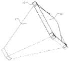
图2是本发明的整体结构图;Fig. 2 is the overall structural diagram of the present invention;
图3是本发明中4×4个阵列天线视图;Fig. 3 is a view of 4 * 4 array antennas in the present invention;
图4是本发明中单个方形喇叭天线视图;Fig. 4 is single square horn antenna view among the present invention;
图5是本发明中方形喇叭天线的剖视图;Fig. 5 is the sectional view of square horn antenna among the present invention;
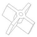
图6是十字形塑料栓的结构图;Fig. 6 is a structural diagram of a cross-shaped plastic plug;
图中:1、天线板,2、波导旋转关节,3、波导,4、低噪声下变频器,5、合路器,6、双工器,7、发射波导关节,8、极化控制器,9、方形喇叭天线,10、介质透镜,11、极化分离器,12、水平极化功分网络,13、垂直极化功分网络,14、十字形塑料栓,15、介质栅板。 In the figure: 1. Antenna board, 2. Waveguide rotary joint, 3. Waveguide, 4. Low-noise downconverter, 5. Combiner, 6. Duplexer, 7. Transmitting waveguide joint, 8. Polarization controller , 9, square horn antenna, 10, dielectric lens, 11, polarization separator, 12, horizontal polarization power distribution network, 13, vertical polarization power distribution network, 14, cross-shaped plastic plug, 15, dielectric grid. the
具体实施方式Detailed ways
下面结合附图和实施例对本发明作进一步说明。The present invention will be further described below in conjunction with drawings and embodiments.
如图1、图2、图3所示,本发明的车载动中通阵列天线由N×M个结构相同的方形喇叭天线9组成,N与M可以相同或不相同个数,图3中为4×4个;每个喇叭天线馈电口处通过一个极化分离器11将方形喇叭天线接收到的垂直极化信号和水平极化信号分离;极化分离器11两个输出端口分别通过各自波导3连接到水平极化功分网络12和垂直极化功分网络13;N×M个方形喇叭天线9、N×M个极化分离器11、水平极化功分网络12、垂直极化功分网络13组成一块天线板1,天线板采用轻质注塑加工,内外表面镀有金属膜;所述两个功分网络在天线板两端分别通过波导旋转关节2与各自的双工器6相连;两个双工器的输入端分别通过波导与发射极化控制器8相连;发射信号TX通过发射波导关节7后输入到发射极化控制器8;两个双工器的输出端分别通过波导与接收合路器5相连,合路器输出信号RX到低噪声下变频器(LNB)模块4;如图4、图5所示,该动中通阵列天线的每个方形喇叭天线口径处均覆盖有一层介质栅板15;介质栅板上方覆盖一块抛物面介质透镜10;介质透镜10和介质栅板15使用四个安装在方形喇叭天线方形口径角上的十字形塑料栓14固定;如图6所示,十字形塑料栓14中心有一螺丝孔,用以固定十字形塑料栓14。As shown in Fig. 1, Fig. 2 and Fig. 3, the vehicle-mounted communication array antenna in motion of the present invention is made up of N * M
如图5所示,所述介质栅板为PP(聚丙烯)材料,其大小与方形喇叭天线的口径大小相同,介质栅板上均匀分布有直径为1毫米的孔。As shown in FIG. 5 , the dielectric grid is made of PP (polypropylene) material, and its size is the same as the diameter of the square horn antenna. Holes with a diameter of 1 mm are evenly distributed on the dielectric grid.
如图5所示,所述介质透镜为PP材料,与介质栅板接触的一面是平面,相对的另外一面为抛物面。As shown in FIG. 5 , the dielectric lens is made of PP material, one side in contact with the dielectric grid plate is a plane, and the opposite side is a paraboloid.
本发明的工作原理如下:The working principle of the present invention is as follows:
方形喇叭天线9组成的阵列可以形成高指向性、高增益的波束。The array composed of
方形喇叭天线9的口径处电磁波的电场分布呈曲面状,口径处的电磁波经过介质透镜10后,曲面状的电场分布变成平面状,因此方形喇叭天线9的增益得到增强;在设计介质透镜10的抛物面弧度时,首先要根据方形喇叭天线9的长度以及口径大小确定天线的辐射中心,然后将抛物面的焦点定在辐射中心进行设计。The electric field distribution of the electromagnetic wave at the aperture place of the
由于介质透镜10与空气之间存在一个交界面,这会影响方形喇叭天线的驻波比,所以在介质透镜与空气之间增加一层介质栅板15来改善方形喇叭天线9的驻波比。Since there is an interface between the
Claims (3)
Translated fromChinesePriority Applications (1)
| Application Number | Priority Date | Filing Date | Title |
|---|---|---|---|
| CN2012105732632ACN103022719A (en) | 2012-12-26 | 2012-12-26 | Vehicle-borne STOM (satcom on the move) array antenna with gain increased by lightweight dielectric lens |
Applications Claiming Priority (1)
| Application Number | Priority Date | Filing Date | Title |
|---|---|---|---|
| CN2012105732632ACN103022719A (en) | 2012-12-26 | 2012-12-26 | Vehicle-borne STOM (satcom on the move) array antenna with gain increased by lightweight dielectric lens |
Publications (1)
| Publication Number | Publication Date |
|---|---|
| CN103022719Atrue CN103022719A (en) | 2013-04-03 |
Family
ID=47971009
Family Applications (1)
| Application Number | Title | Priority Date | Filing Date |
|---|---|---|---|
| CN2012105732632APendingCN103022719A (en) | 2012-12-26 | 2012-12-26 | Vehicle-borne STOM (satcom on the move) array antenna with gain increased by lightweight dielectric lens |
Country Status (1)
| Country | Link |
|---|---|
| CN (1) | CN103022719A (en) |
Cited By (3)
| Publication number | Priority date | Publication date | Assignee | Title |
|---|---|---|---|---|
| CN110637393A (en)* | 2017-06-05 | 2019-12-31 | 日立汽车系统株式会社 | Antennas, array antennas, radar devices and in-vehicle systems |
| CN112636004A (en)* | 2019-10-09 | 2021-04-09 | 安徽工业大学 | Metamaterial focusing antenna for measuring space-time evolution of streamer electron density |
| CN115483541A (en)* | 2022-09-06 | 2022-12-16 | 中国工程物理研究院应用电子学研究所 | Ka-band high-power beam scanning array antenna based on polarization torsion |
Citations (5)
| Publication number | Priority date | Publication date | Assignee | Title |
|---|---|---|---|---|
| CN1144019A (en)* | 1994-02-26 | 1997-02-26 | 福特尔技术有限公司 | Microwave antennas |
| CN1682402A (en)* | 2002-08-20 | 2005-10-12 | 爱罗莎特股份有限公司 | Communication system with broadband antenna |
| US6992639B1 (en)* | 2003-01-16 | 2006-01-31 | Lockheed Martin Corporation | Hybrid-mode horn antenna with selective gain |
| CN101699659A (en)* | 2009-11-04 | 2010-04-28 | 东南大学 | Lens antenna |
| CN101777695A (en)* | 2009-07-03 | 2010-07-14 | 南京迅诺电子科技有限公司 | Vehicle-mounted Ku wave band satellite communication small-bore antenna system |
- 2012
- 2012-12-26CNCN2012105732632Apatent/CN103022719A/enactivePending
Patent Citations (5)
| Publication number | Priority date | Publication date | Assignee | Title |
|---|---|---|---|---|
| CN1144019A (en)* | 1994-02-26 | 1997-02-26 | 福特尔技术有限公司 | Microwave antennas |
| CN1682402A (en)* | 2002-08-20 | 2005-10-12 | 爱罗莎特股份有限公司 | Communication system with broadband antenna |
| US6992639B1 (en)* | 2003-01-16 | 2006-01-31 | Lockheed Martin Corporation | Hybrid-mode horn antenna with selective gain |
| CN101777695A (en)* | 2009-07-03 | 2010-07-14 | 南京迅诺电子科技有限公司 | Vehicle-mounted Ku wave band satellite communication small-bore antenna system |
| CN101699659A (en)* | 2009-11-04 | 2010-04-28 | 东南大学 | Lens antenna |
Cited By (5)
| Publication number | Priority date | Publication date | Assignee | Title |
|---|---|---|---|---|
| CN110637393A (en)* | 2017-06-05 | 2019-12-31 | 日立汽车系统株式会社 | Antennas, array antennas, radar devices and in-vehicle systems |
| CN112636004A (en)* | 2019-10-09 | 2021-04-09 | 安徽工业大学 | Metamaterial focusing antenna for measuring space-time evolution of streamer electron density |
| CN112636004B (en)* | 2019-10-09 | 2022-09-13 | 安徽工业大学 | Metamaterial focusing antenna for measuring space-time evolution of streamer electron density |
| CN115483541A (en)* | 2022-09-06 | 2022-12-16 | 中国工程物理研究院应用电子学研究所 | Ka-band high-power beam scanning array antenna based on polarization torsion |
| CN115483541B (en)* | 2022-09-06 | 2025-03-18 | 中国工程物理研究院应用电子学研究所 | A Ka-band high-power beam scanning array antenna based on polarization twisting |
Similar Documents
| Publication | Publication Date | Title |
|---|---|---|
| Chaloun et al. | Electronically steerable antennas for future heterogeneous communication networks: Review and perspectives | |
| CN105024143B (en) | A kind of chip Ka frequency ranges large-angle scanning satellite communication antena | |
| CN103022727B (en) | Low section communication in moving transmit-receive sharing one dimension active phase array antenna | |
| WO2020015386A1 (en) | Beam reconstruction method, antenna, microwave device, and network system | |
| CN204857954U (en) | A Ka-band wide-angle scanning phased array antenna | |
| Zhou et al. | Evolution of satellite communication antennas on mobile ground terminals | |
| CN104092485B (en) | Distributed Lightweight Shaped Antenna for Communication in Motion | |
| CN103390798B (en) | Satellite communication in motion dual polarization four ridge side trumpet array antenna | |
| US10454186B2 (en) | Lightweight plastic antenna | |
| US9318807B2 (en) | Stacked septum polarizer and feed for a low profile reflector | |
| US11095044B2 (en) | Combined omnidirectional and directional antennas | |
| CN109193154A (en) | A kind of millimeter wave circular polarisation multi-beam plate cylindrical dielectric lens antenna | |
| CN102460831A (en) | Vehicle antenna device with horizontal main beam direction | |
| Schneider et al. | The multiple spot beam antenna project “Medusa” | |
| CN103022719A (en) | Vehicle-borne STOM (satcom on the move) array antenna with gain increased by lightweight dielectric lens | |
| CN117810716A (en) | Circular polarization hybrid array antenna and hybrid array antenna control method | |
| CN204407499U (en) | Antenna, antenna system and communication equipment | |
| CN113328244B (en) | An End-Fire Conformal Photovoltaic Antenna Based on Curved Surface Structure | |
| CN105428816A (en) | Left-handed and right-handed double circular polarized wide beam antenna | |
| CN204407484U (en) | Antenna, antenna system and communication equipment | |
| CN204407497U (en) | Antenna, antenna system and communication equipment | |
| CN116544679A (en) | An electromagnetic lens-based receiving antenna and its design method | |
| Goel et al. | A CRLH-SIW based Frequency-Reconfigurable Antenna for LEO to GEO Inter-Satellite Link | |
| CN103594806A (en) | Thin-substrate amplitude correction slot-line planar horn antenna | |
| CN204407494U (en) | Antenna, antenna system and communication equipment |
Legal Events
| Date | Code | Title | Description |
|---|---|---|---|
| C06 | Publication | ||
| PB01 | Publication | ||
| C10 | Entry into substantive examination | ||
| SE01 | Entry into force of request for substantive examination | ||
| C02 | Deemed withdrawal of patent application after publication (patent law 2001) | ||
| WD01 | Invention patent application deemed withdrawn after publication | Application publication date:20130403 |