CN102971778A - Reflective decoration assembly - Google Patents
Reflective decoration assemblyDownload PDFInfo
- Publication number
- CN102971778A CN102971778ACN2011800242170ACN201180024217ACN102971778ACN 102971778 ACN102971778 ACN 102971778ACN 2011800242170 ACN2011800242170 ACN 2011800242170ACN 201180024217 ACN201180024217 ACN 201180024217ACN 102971778 ACN102971778 ACN 102971778A
- Authority
- CN
- China
- Prior art keywords
- frame
- assembly
- dish
- attachment post
- framework
- Prior art date
- Legal status (The legal status is an assumption and is not a legal conclusion. Google has not performed a legal analysis and makes no representation as to the accuracy of the status listed.)
- Pending
Links
Images


Classifications
- G—PHYSICS
- G09—EDUCATION; CRYPTOGRAPHY; DISPLAY; ADVERTISING; SEALS
- G09F—DISPLAYING; ADVERTISING; SIGNS; LABELS OR NAME-PLATES; SEALS
- G09F13/00—Illuminated signs; Luminous advertising
- G09F13/16—Signs formed of or incorporating reflecting elements or surfaces, e.g. warning signs having triangular or other geometrical shape
- G09F13/165—Signs formed of or incorporating reflecting elements or surfaces, e.g. warning signs having triangular or other geometrical shape rotatably or swingatly mounted reflecting elements or surfaces
- Y—GENERAL TAGGING OF NEW TECHNOLOGICAL DEVELOPMENTS; GENERAL TAGGING OF CROSS-SECTIONAL TECHNOLOGIES SPANNING OVER SEVERAL SECTIONS OF THE IPC; TECHNICAL SUBJECTS COVERED BY FORMER USPC CROSS-REFERENCE ART COLLECTIONS [XRACs] AND DIGESTS
- Y10—TECHNICAL SUBJECTS COVERED BY FORMER USPC
- Y10T—TECHNICAL SUBJECTS COVERED BY FORMER US CLASSIFICATION
- Y10T428/00—Stock material or miscellaneous articles
- Y10T428/17—Three or more coplanar interfitted sections with securing means
Landscapes
- Physics & Mathematics (AREA)
- Geometry (AREA)
- General Physics & Mathematics (AREA)
- Engineering & Computer Science (AREA)
- Theoretical Computer Science (AREA)
- Illuminated Signs And Luminous Advertising (AREA)
- Non-Portable Lighting Devices Or Systems Thereof (AREA)
- Mirrors, Picture Frames, Photograph Stands, And Related Fastening Devices (AREA)
Abstract
Description
Translated fromChinese技术领域technical field
本发明总体上涉及反光装饰品,并且更明确地说涉及反光装饰性组件,这种反光装饰性组件包括可枢转盘并且可用以形成标志或其他装饰性元件。The present invention relates generally to reflective decorative articles, and more particularly to reflective decorative assemblies that include pivotable discs and that can be used to form signs or other decorative elements.
背景技术Background technique
标志以及其他装饰性元件有无数的应用。具有特定视觉冲击的一类标志利用支撑在对应的盘支撑柱阵列上的反光盘阵列。防止每个盘从柱移除,但又同时允许相对于其所附接到的柱做一定程度的移动。典型地,这些盘涂布有反光材料,并且当从远处观看时,移动中盘的阵列提供闪光表面的外观。另外地,可以选择每个盘的颜色,使得当从远处观看时,盘阵列会拼成字、形成图案或造出图像。Signs, as well as other decorative elements, have countless applications. One type of sign with a particular visual impact utilizes an array of reflective discs supported on a corresponding array of disc support posts. Each disk is prevented from being removed from the column, but at the same time is allowed to do a certain degree of movement relative to the column to which it is attached. Typically these pans are coated with a reflective material and the array of pans in motion provides the appearance of a shiny surface when viewed from a distance. Additionally, the color of each disc can be chosen such that the array of discs spells out words, forms patterns, or creates images when viewed from a distance.
在大多数的安装中,盘阵列是通过将销子或小钉子按压穿过盘中的预成型孔隙中并且接着将钉子插入到支撑表面中来一次一个地安装。这种安装盘的方法提供用于每个标志或装饰表面的大量定制,但由于典型应用中需要大量盘而明显是非常费时的。另外地,当个别地安装每个盘以及柱时,难以确保每个盘之间的均匀间隔。In most installations, arrays of disks are installed one at a time by pressing pins or small nails through pre-formed apertures in the disks and then inserting the nails into the support surface. This method of mounting discs provides for extensive customization for each sign or decorative surface, but is obviously very time consuming due to the large number of discs required in typical applications. Additionally, it is difficult to ensure even spacing between each disc when each disc and post are mounted individually.
通过具有可用于盘的放置以及支撑的盘附接柱阵列的薄片方便了反光盘的一些安装。然而,该薄片是实心的,这限制了盘的移动、标志的视觉吸引力,以及在安装期间对标志的形状以及大小进行定制的能力。通过支撑单行盘的框架方便了其他的安装。然而,在安装期间,行之间的均匀性难以实现,并且在单行框架上的预载图像难以在现场组装。Some mounting of reflective discs is facilitated by the sheet having an array of disc attachment posts available for disc placement and support. However, the sheet is solid, which limits the movement of the disc, the visual appeal of the logo, and the ability to customize the shape and size of the logo during installation. Other installations are facilitated by the frame supporting the single row discs. However, uniformity between rows is difficult to achieve during installation, and preloaded images on single-row frames are difficult to assemble on site.
在盘阵列放置在支撑结构上之后,改善盘闪光效果的一个方法是提供将光引导到盘表面上的光源。一般来说,这是用一个或多个光源来完成的,这一个或多个光源与盘隔开(即,分离)并且指向盘的可视表面。不幸的是,当物体或人来到光源与盘之间时,会防止光源照到盘。例如,如果应用是红地毯盛会中的背景,在红地毯盛会中背景是平行于地毯的路径而延伸,那么走红地毯的人有可能会走到光源与支撑结构之间。One way to improve the disc flash effect after the disc array is placed on the support structure is to provide a light source that directs light onto the disc surface. Typically, this is accomplished with one or more light sources spaced (ie, separate) from the disc and directed toward the viewable surface of the disc. Unfortunately, when an object or person comes between the light source and the disc, it prevents the light source from hitting the disc. For example, if the application is a backdrop at a red carpet event where the backdrop runs parallel to the path of the carpet, it is possible for a red carpet walker to walk between the light source and the supporting structure.
因此,需要克服如上所述的现有技术的问题。Therefore, there is a need to overcome the problems of the prior art as described above.
发明内容Contents of the invention
本发明提供一种反光装饰品组件,这种反光装饰品组件克服此总体类型的迄今已知的装置和方法的迄今提到的缺点。The present invention provides a retroreflective decoration assembly which overcomes the heretofore mentioned disadvantages of hitherto known devices and methods of this general type.
鉴于前述以及其他目标,根据本发明,提供了一种反光装饰品组件,该反光装饰品组件包括一个框架,该框架具有一对相对的框架边缘以及多个第一框架支撑件,其中每个框架支撑件是安排在具有至少两个其他第一框架支撑件的一个平面中、是安排在由该对相对的框架边缘限定的一个平面中、具有在该对相对的框架边缘之间的一部分、并且基本上平行于至少一个其他的第一框架支撑件。该反光装饰品组件也具有多个第二框架支撑件,该多个第二框架支撑件各自与这些第一框架支撑件中的至少两个安排成一种相交构型中,由此限定多个框架空隙。多个盘附接柱具有附接到该框架上的一个第一末端以及与该第一末端分开一段预定距离的一个第二末端,该第二末端在其处具有一个盘固持头。多个盘具有在其中限定一个孔的一个表面,并且,当安装在盘附接柱上时,该孔环绕这些盘附接柱之一的长度的一部分并且具有比该头的一个对应尺寸小的至少一个尺寸。In view of the foregoing and other objects, and in accordance with the present invention, there is provided a reflective ornamental assembly comprising a frame having a pair of opposing frame edges and a plurality of first frame supports, wherein each frame the support is arranged in a plane with at least two other first frame supports, is arranged in a plane defined by the pair of opposing frame edges, has a portion between the pair of opposing frame edges, and substantially parallel to at least one other first frame support. The reflective ornament assembly also has a plurality of second frame supports each arranged in an intersecting configuration with at least two of the first frame supports, thereby defining a plurality of frames void. Disk attachment posts have a first end attached to the frame and a second end spaced a predetermined distance from the first end, the second end having a disk retaining head therein. The discs have a surface defining a hole therein and, when mounted on the disc attachment posts, the hole encircles a portion of the length of one of the disc attachment posts and has a corresponding dimension smaller than the head. At least one size.
根据另一个特征,本发明的一个实施方案包括在这些盘固持头中的至少一个处的一个发光体,诸如LED或光导管。According to another feature, an embodiment of the invention comprises at least one of the disc holding heads a light emitter, such as an LED or a light guide.
根据本发明的一个另外特征,每个盘附接柱的第一末端实质上在这些第一框架支撑件中之一与这些第二框架支撑件之一的一个相交点处附接到框架。According to a further characteristic of the invention, the first end of each disc attachment post is attached to the frame substantially at an intersection of one of the first frame supports and one of the second frame supports.
根据本发明的一个另外特征,盘的至少一个尺寸大于孔的最大尺寸。According to a further characteristic of the invention, at least one dimension of the disc is greater than the largest dimension of the hole.
根据另一个特征,本发明的一个实施方案包括沿着该多个第一框架支撑件以及该多个第二框架支撑件中的至少一个的弱点线,这些弱点线提供即时的框架定大小位置。According to another feature, an embodiment of the invention includes lines of weakness along at least one of the first plurality of frame supports and at least one of the second plurality of frame supports, the lines of weakness providing immediate frame sizing locations.
根据本发明,揭示一种用于提供一个框架的方法,该框架包括一对相对的框架边缘以及多个第一框架支撑件,其中每个框架支撑件是安排在具有至少两个其他第一框架支撑件的一个平面中、是安排在由该对相对的框架边缘限定的一个平面中、具有在该对相对的框架边缘之间的一部分、并且基本上平行于至少一个其他的第一框架支撑件。该框架包括多个第二框架支撑件,其中每个第二框架支撑件是与这些第一框架支撑件中的至少两个安排成一种相交构型,由此限定多个框架空隙;以及多个盘附接柱,该多个盘附接柱各自具有附接到框架上的一个第一末端以及与该第一末端分开一段预定距离的一个第二末端。该方法还包括:提供多个盘,该多个盘中的每一个都具有在其中限定一个孔的一个表面;将该孔放置在越过这些盘附接柱中的一个的这些盘中的一个中;以及在单个步骤中使这些盘附接柱的多个第二末端变形以形成一个盘固持头,该盘固持头具有大于该盘中的该孔的一个对应尺寸的至少一个尺寸。According to the present invention, there is disclosed a method for providing a frame comprising a pair of opposing frame edges and a plurality of first frame supports, wherein each frame support is arranged with at least two other first frame the support is arranged in a plane defined by the pair of opposing frame edges, has a portion between the pair of opposing frame edges, and is substantially parallel to at least one other first frame support in a plane . The frame includes a plurality of second frame supports, wherein each second frame support is arranged in an intersecting configuration with at least two of the first frame supports, thereby defining a plurality of frame voids; and a plurality of The disc attachment posts each have a first end attached to the frame and a second end separated from the first end by a predetermined distance. The method also includes: providing a plurality of discs, each of the plurality of discs having a surface defining a hole therein; placing the hole in one of the discs over one of the disc attachment posts and deforming the second ends of the disk attachment posts in a single step to form a disk holding head having at least one dimension greater than a corresponding dimension of the hole in the disk.
根据本发明的另一个特征,该变形步骤包括熔化这些盘附接柱的第二末端,并且还可以包括在这些盘附接柱的第二末端处限定一个凸起形状。According to another feature of the invention, the deforming step includes melting the second ends of the disc attachment posts, and may also include defining a raised shape at the second ends of the disc attachment posts.
根据本发明的一个另外特征,在该凸起形状的一个表面上提供一个反光涂层。According to a further characteristic of the invention, a reflective coating is provided on one surface of the raised shape.
根据又另一个特征,本发明的一个实施方案在这些盘附接柱中的至少一个中形成一个发光体。According to yet another feature, an embodiment of the invention forms a light in at least one of the disc attachment posts.
根据本发明的一个另外的特征,形成从框架上的多个位置到这些盘附接柱中的至少两个的至少两个独特的光路。According to a further feature of the invention, at least two unique optical paths are formed from locations on the frame to at least two of the disc attachment posts.
尽管本发明在此被图示以及描述为体现成反光装饰品组件,不过,并不意在限于所示的细节,因为在不脱离本发明的精神的情况下并且在权利要求书的等效物的范畴和范围之内,可以对本发明做出各种修改以及结构改变。另外地,将不会详细描述本发明的示例性实施方案的熟知元件或会将其省去以免混淆本发明的相关细节。While the invention is illustrated and described herein as embodied in a retroreflective ornamental assembly, it is not intended to be limited to the details shown, since the present invention is not intended to be limited to the details shown, as long as it does not depart from the spirit of the invention and within the scope of equivalents of the claims. Various modifications and structural changes can be made to the present invention within the scope and scope. Additionally, well-known elements of the exemplary embodiments of the invention will not be described in detail or will be omitted so as not to obscure the relevant details of the invention.
被视为本发明的特性的其他特征在随附权利要求书中陈述。如所要求,在此披露了本发明的详细实施方案;然而,应当理解,所披露的实施方案仅例证可体现为各种形式的本发明。因此,在此披露的特定结构和功能细节不应被解释为限制性的,而是仅作为权利要求书的基础以及作为用于以实质上任何适当详细的结构来教导本领域的普通技术人员不同地采用本发明的代表性基础。另外,在此使用的术语和短语不意在为限制性的;而是,意在提供对本发明的可理解的描述。虽然说明书是以限定了被视为是新颖的本发明特征的权利要求书结束,但是人们相信,考虑以下描述以及图式将更好地理解本发明,在图式中,相似参考数字接后。图式中的各图不按比例绘制。Other characteristics which are considered as characteristic of the invention are set forth in the appended claims. As required, detailed embodiments of the present invention are disclosed herein; however, it is to be understood that the disclosed embodiments are merely illustrative of the invention which may be embodied in various forms. Therefore, specific structural and functional details disclosed herein are not to be interpreted as limiting, but merely as a basis for the claims and as a useful basis for teaching one of ordinary skill in the art in substantially any appropriately detailed structure. The representative basis of the present invention is employed. Additionally, the terms and phrases used herein are not intended to be limiting; rather, they are intended to provide an understandable description of the invention. While the specification concludes with claims defining the features of the invention which are regarded as novel, it is believed that the invention will be better understood from consideration of the following description together with the drawings in which like reference numerals follow. The figures in the drawings are not drawn to scale.
在披露以及描述本发明之前,应当理解,在此使用的术语是仅用于描述特定实施方案的目的并且不意在为限制性的。如在此使用的,术语“一个”被定义为一个或一个以上。如在此使用的,术语“多个”被定义为两个或两个以上。如在此使用的,术语“另一个”被定义为至少一个第二者或更多个。如在此使用的,术语“包括”和/或“具有”被定义为包括(即,开放性语言)。如在此使用的,术语“联接”被定义为连接,尽管未必是直接的,并且未必是机械上的。如在此使用的,术语“大约”或“近似”适用于所有数值,无论是否明确指出。这些术语一般是指本领域的普通技术人员将认为等效于所述值(即,具有相同的功能或结果)的数值范围。在许多情况下,这些术语可以包括圆整到最近的有效数字的数值。在本文献中,术语“纵向”应当被理解为表示在与装饰性框架的支撑构件的细长方向对应的方向上。Before the present invention is disclosed and described, it is to be understood that the terminology used herein is for the purpose of describing particular embodiments only and is not intended to be limiting. As used herein, the term "a" is defined as one or more than one. As used herein, the term "plurality" is defined as two or more. As used herein, the term "another" is defined as at least a second or more. As used herein, the terms "comprising" and/or "having" are defined as including (ie, open language). As used herein, the term "coupled" is defined as connected, although not necessarily directly, and not necessarily mechanically. As used herein, the term "about" or "approximately" applies to all numerical values, whether expressly stated or not. These terms generally refer to a range of values that one of ordinary skill in the art would consider to be equivalent to the recited value (ie, having the same function or result). In many instances, these terms may include numerical values rounded to the nearest significant figure. In this document, the term "longitudinal" is understood to mean the direction corresponding to the elongate direction of the support members of the decorative frame.
附图说明Description of drawings
附图用以进一步图示各种实施方案以及解释所有根据本发明的不同原理以及优点,在附图中,相似的参考数字指代贯穿这些分离的视图中的相同或功能类似的元件,并且与下文的详细描述一起并入并且形成本说明书的一部分。The accompanying drawings serve to further illustrate various embodiments and explain all of the various principles and advantages in accordance with the present invention, and in the drawings, like reference numerals designate identical or functionally similar elements throughout the separate views, and with The following detailed description is incorporated together and forms a part of this specification.
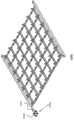
图1是根据本发明的装饰性框架结构的透视图;Figure 1 is a perspective view of a decorative frame structure according to the present invention;
图2是根据本发明的装饰性盘的立面图;Figure 2 is an elevational view of a decorative tray according to the invention;
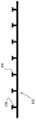
图3是根据本发明的具有变形的盘固持头的装饰框架结构的立面边视图;Figure 3 is an elevational side view of a decorative frame structure with a deformed disc holding head in accordance with the present invention;
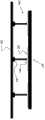
图4是根据本发明的装饰性框架结构的立面边视图,其中这些装饰性盘放置在未变形的盘固持头上面并且一个变形板邻近该装饰性框架结构;Figure 4 is an elevational side view of a decorative frame structure according to the present invention with the decorative disks placed over undeformed disk holding heads and a deformed plate adjacent to the decorative frame structure;
图5是根据本发明的图4的装饰性框架结构的立面边视图,其中变形板与装饰性框架结构的多个盘固持头接触并且使盘固持头变形;5 is an elevational side view of the decorative frame structure of FIG. 4 with a deformable plate in contact with and deforming a plurality of disc retention heads of the decorative frame structure in accordance with the present invention;
图6是根据本发明的示例性实施方案的制造装饰性框架组件的方法的过程流程图;6 is a process flow diagram of a method of manufacturing a decorative frame assembly according to an exemplary embodiment of the present invention;
图7是根据本发明的图5的装饰性框架结构的另一个示例性实施方案的立面边视图;7 is an elevational side view of another exemplary embodiment of the decorative frame structure of FIG. 5 in accordance with the present invention;
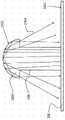
图8是根据本发明的具有光源附接到其上的装饰性框架结构的一个另外的示例性实施方案的立面图;8 is an elevational view of an additional exemplary embodiment of a decorative frame structure having light sources attached thereto in accordance with the present invention;
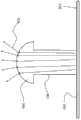
图9是根据本发明的发光盘固持头的示例性实施方案的立面图;9 is an elevational view of an exemplary embodiment of a light emitting disc holding head according to the present invention;
图10是根据本发明的光反射盘固持头的示例性实施方案的立面图;10 is an elevational view of an exemplary embodiment of a light reflective disc holding head according to the present invention;
图11是根据本发明的产生光的盘固持头的示例性实施方案的立面图;Figure 11 is an elevational view of an exemplary embodiment of a disc holding head generating light according to the present invention;
图12是框架带有根据本发明的具有锁定方式的示例性实施方案的透视图;Figure 12 is a perspective view of a frame with an exemplary embodiment having a locking means according to the present invention;
图13是根据本发明的在两个邻近的装饰性框架结构之间的光传输联接的透视图;13 is a perspective view of a light transmission coupling between two adjacent decorative frame structures in accordance with the present invention;
图14是根据本发明的实施方案的具有电触点以及弱点线的图1的装饰性框架结构的透视图;14 is a perspective view of the decorative frame structure of FIG. 1 with electrical contacts and lines of weakness in accordance with an embodiment of the present invention;
图15是根据本发明的实施方案的具有单独的光路的图1的装饰性框架结构的透视图;15 is a perspective view of the decorative frame structure of FIG. 1 with separate light paths in accordance with an embodiment of the present invention;
图16是根据本发明的实施方案的链接块的立面边视图;以及Figure 16 is an elevational side view of a link block according to an embodiment of the invention; and
图17是根据本发明的实施方案的图16的链接块的立面仰视图。17 is an elevational bottom view of the link block of FIG. 16 according to an embodiment of the present invention.
具体实施方式Detailed ways
虽然说明书对限定了被视为是新颖的本发明特征的权利要求进行了总结,但是相信的是,通过考虑以下描述以及图式将更好地理解本发明,在图式中,相似参考数字接后。应当理解,所披露的实施方案仅例证可以体现为各种形式的本发明。While the specification concludes with claims defining the features of the invention which are regarded as novel, it is believed that the invention will be better understood from consideration of the following description and drawings in which like reference numerals follow back. It is to be understood that the disclosed embodiments are merely illustrative of the invention which may be embodied in various forms.
本发明提供一种新颖且有效的反光装饰品组件。本发明的实施方案提供改善了的盘紧固和安装结构。另外,本发明的实施方案提供改善的视觉上刺激的标志。The present invention provides a novel and effective retroreflective ornamental assembly. Embodiments of the present invention provide improved disc fastening and mounting structures. In addition, embodiments of the present invention provide improved visually stimulating markers.
现在参考图1,示出本发明的一个实施方案的透视图。该图示出本发明的几个有利特征,但是如下文将描述的,这决不是窄化,因为本发明可以按照几种形状、大小、特征和部件的组合,以及部件的变化的数目和功能来提供。如图1所示,发明性反光装饰品组件的第一部件是一个框架100,该框架在稍后的步骤中提供对多个盘200(此视图中未示出)的支撑,该多个盘最终会驻留在该反光装饰品组件上。框架100包括彼此相对的第一对框架边缘102。在所示的实施方案中,这些框架边缘102实质上彼此平行。然而,框架边缘102可取决于装饰性组件的性质而采取各种构型,这些构型包括并行以及不平行。Referring now to Figure 1, a perspective view of one embodiment of the present invention is shown. The figure shows several advantageous features of the invention, but as will be described below, this is by no means narrowing, since the invention can be in several shapes, sizes, combinations of features and components, and varying numbers and functions of components to provide. As shown in Figure 1, the first component of the inventive retroreflective ornament assembly is a
该组件的这些框架边缘102是通过多个框架支撑件104来连接的。在一个实施方案中,这些框架支撑件104位于由这些框架边缘102限定的一个平面内并且彼此平行。然而,不要求任何特定数目的框架支撑件,或任两个都彼此平行。如在图1中可看出的,就是这些框架边缘102以及框架支撑件104形成了框架100的基本结构。尽管至少两个框架支撑件104是优选的,并且如图1所示,也可以包括额外的框架支撑件104。自然地,存在与这些结构支撑件104的数目一致的结构支撑件增加。The frame edges 102 of the assembly are connected by frame supports 104 . In one embodiment, the frame supports 104 lie in a plane defined by the frame edges 102 and are parallel to each other. However, it is not required that any particular number of frame supports, or that any two be parallel to each other. As can be seen in FIG. 1 , it is these frame edges 102 and frame supports 104 that form the basic structure of the
另外地,可以提供多个辅助框架支撑件106,这些辅助框架支撑件在与这些第一框架支撑件104的纵向方向不同的方向上横跨。在图1所示的一个实施方案中,这些辅助框架支撑件106与第一框架支撑件104相交并且基本上平行于这些相对的框架边缘102。这些第一框架支撑件104以及辅助框架支撑件106限定多个框架空隙103。然而,这种垂直/平行对准仅为示例性的并且不是要求的。这些辅助框架支撑件106提供对框架100的额外斜撑。由于组件的大小可能会基于项目而不同,因此这些辅助框架支撑件106改善了框架100并且当然整个反光装饰品组件(一旦在一起)的总体稳定性。另外地,框架100上包括的这些框架支撑件104以及辅助框架支撑件106的数目可基于反光装饰品组件的复杂度以及大小而变化。因为该框架被预想为具有多个纵向构件,诸如多个相对的框架边缘102、多个第一框架支撑件104、以及多个第二框架支撑件106,如图1所示,所以仅用一对切割器就可以容易且快速地移除框架/组件的多个部分来针对特定应用定制框架的形状。移除框架100的区段将不会实质上不利于框架100的总体刚性。Additionally, auxiliary frame supports 106 may be provided which span in a direction different from the longitudinal direction of the first frame supports 104 . In one embodiment shown in FIG. 1 , the secondary frame supports 106 intersect the first frame supports 104 and are substantially parallel to the opposing frame edges 102 . The first frame supports 104 and the auxiliary frame supports 106 define a plurality of frame voids 103 . However, such vertical/parallel alignment is exemplary only and not required. These auxiliary frame supports 106 provide additional diagonal bracing to the
根据一个实施方案,框架100还包括从框架支撑件104突出的多个盘附接柱108。在一些情况下,尽管不是必需的,但是这些盘附接柱108是处在这些第一框架支撑件104与辅助框架支撑件106之间的相交点处。盘附接柱108的第一端被在一个框架支撑件104上或一个框架支撑件104与一个辅助框架支撑件106的相交点处附接到框架100上。这些盘附接柱108接着远离框架100向外延伸了一段预定的长度。According to one embodiment, the
本发明还包括多个盘200,如图2所示。这些盘200可以具有无数的形状或轮廓,并且决不限于图2所绘示的八边形形状。另外地,盘200可以取决于反光装饰品组件的希望的效果而为平面的或具有三维轮廓的,诸如弯曲。每个盘200含有一个盘孔202。孔202可以如图2所示是圆形的,但不限于一个特定形状或轮廓。The present invention also includes a plurality of
通过盘孔202将每个盘200放置到盘附接柱108上。盘孔202的直径大于盘附接柱108的直径。此大小差异允许盘200一旦被放置在盘附接柱108上就能以一定的自由度来移动。一旦将盘200放置在盘附接柱108上,便形成盘固持头300,如图3的侧视图中所示。Each
根据本发明的一个实施方案,通过使用加热元件(例如,热板)来形成这些头300,该加热元件向下压在这些盘附接柱108的上端上并且熔化该上端以形成这些盘固持头300并且产生图3所示的形状。这个过程在图4和5中进行图示,并且在图6的流程图中示出。According to one embodiment of the invention, the
图4示出根据本发明的发明性组件400的立面侧视图。盘组件400包括指向在向上位置中的盘附接柱108的框架100。一旦框架100可用,便将这些盘200插在盘附接柱108上,使得每个盘200的孔202(在图4的这个侧视图中不可见)放置在盘附接柱108上。这开头的两个步骤在图6的过程流程图中示出并且指示为步骤602和604。再回来看图4,在这个侧视图中,可以看出的是可以通过将这些盘200后退(在这个视图中是向上方向)滑出盘附接柱108来容易地移除它们。换句话说,在这些盘附接柱108上是没有结构会防止将盘移除的。Figure 4 shows an elevational side view of an
在图4中还示出位于盘组件400上方的一个热板402。在一个另外的步骤(图6中的606)中,使框架100并且明确地说是这些盘附接柱108的上部部分与热板402接触。这在图5中示出。由于热板402所供应的热量,这些盘附接柱108以使其未变形尺寸膨胀以产生多个盘固持头300的方式来变形,其中在一个实施方案中,盘附接柱是由丁酸酯或肖氏A聚碳酸酯制成,但可以是任何可变形材料。在发生了熔化或变形之后,在步骤608中,移除热板402,从而提供完成的组件400,在图7中示出了该组件的一部分。请注意,尽管已描述了热板以及加热方法,但是也可以使用其他制造过程来产生这些盘固持头300而不偏离本发明的精神。Also shown in FIG. 4 is a
优选地,如在图7中可看出,在熔化步骤606完成之后,盘固持头300的直径大于盘孔202的至少一个尺寸。尽管在此提到了术语“直径”,但是盘附接柱108、头300以及盘孔202不限于圆形形状。“直径”也可指本发明的任一元件的形状或尺寸的最大宽度。例如,盘孔202的形状不要求是圆的,并且可以是卵形、正方形、或任何其他形状。一般来说,只要孔202的至少一个尺寸小于头300的对应尺寸,那么盘固持头300将会防止或阻止盘200从盘附接柱108移除。然而,可预想到这些盘200将由易弯的材料制成,使得甚至在形成盘固持头300之后,仍然可以通过简单地施加适当量的力以及使盘200变形来将盘200从盘附接柱108上移除。Preferably, as can be seen in FIG. 7 , after the
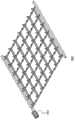
图7提供了反光盘组件400的一部分的自顶向下的立面图,其中多个盘200位于盘附接柱108上,柱的末端被烧成头300以防止盘200从柱108上移除。显著地,每个柱108都具有限定框架100的主平面与头300之间的距离“D”的长度。因为每个盘200的厚度“T”小于距离“D”,所以例如在空气吹过它们时,盘200能够在柱108上移动。当盘200具备反光饰面时,结果是一类闪光。在普遍的使用中,盘200将是很多的,并且当放置在组件400上时,结果类似于看到水反射光。7 provides a top-down elevation view of a portion of a
返回参考图1,可看出框架100具备多个安装孔110。这些安装孔提供可以使用螺钉、钉子、钩子或其他附接机构将框架100以及整个盘组件400紧固到一个结构上的位置。具有框架100的装饰性盘组件提供优于单独地将每个盘钉到一个表面上的现有技术方法的许多益处。通过利用框架100,这些盘被可靠地在彼此之间维持了一种均匀的距离。另外地,这些框架可以在远程位置处进行组装,并且然后简单地在现场安装,而对所要求细节的关注要少得多。例如,在一些应用中,使用多种颜色的盘200来造出复杂的图像。这个细节可能会超出被雇来组装标志的工人的能力之外。组装位置也可能难以接近,诸如高的宣传牌,并且对盘的令人生厌的选择以及安装将是困难或不可能的。此外,如上所述,预先建造的框架组件400允许如上所述地用简单的过程来将盘200紧固到框架100上。Referring back to FIG. 1 , it can be seen that the
另外地,因为框架100是由构件102、104、106的矩阵形成,所以通过仅与框架一起提供(例如)一对切割器以移除组件400的多个区段,就有可能完成定制。此外,如下文将描述的,本发明可以具备用于将邻近框架扣在一起的便利结构,以用于快速安装以及对盘之间间隔的完全控制。Additionally, because the
在本发明的另一个实施方案中,提供了在框架100内的或与框架100接触的一个光源。作为一个实例,图8示出具有联接到框架800上的光源802的框架800。例如,光源802可以是例如发光二极管(LED)、激光器、灯泡、或可以将光引入框架800中的任何其他装置。在这个实施方案中,框架800是由传导光的材料制成。经由光导体(一般被称作“光纤”)进行的光通信在本领域中是熟知的。在图8所示的实施方案中,由光源802产生或传递的光行进穿过框架800。对框架元件进行抛光以及弯曲的熟知技术可以优化光传输以及转向能力。当光从框架800射出时,实现了改善的外观。例如,可以使整个框架发亮,使得可以从远处看到整个结构。可替代地,可以使光仅从框架800的特定部分射出。例如,使用当前的光纤转向以及抛光技术,光可以仅从每个柱108的头300处或附近射出。In another embodiment of the present invention, a light source within or in contact with the
图9示出了射出光的头900的一个特定实施方案,因此,极大地改善了组件的总体视觉效果。在这个实施方案中,尽管不是必需的,但是头900是弯曲的。可以通过(例如)利用具有弯曲压痕的热板402来容易地实现弯曲。当光902在管内穿过框架800时,它最终是从位于盘200的表面901与观看者之间的头900射出。Figure 9 shows a particular embodiment of a
在图10所示的另一个实施方案中,头1000将光反射回到盘200的可视表面1001上,因此极大地改善了组件的总体视觉效果。在这个实施方案中,弯曲的头1000的弯曲表面1002具备一个反光涂层,即,具有一个镜面内表面,这使光1004被引导到盘200的表面1001上。In another embodiment shown in Figure 10, the
作为确保光只能够从框架800的选定区域逃逸的一种方式,框架可以刷有或涂布有(例如)黑漆。在这个实施方案中,例如,如果框架是由透明的塑料型材料制成,那么仅暴露(即,未涂漆)区域会射出光。As a way of ensuring that light is only able to escape from selected areas of the
在本发明的又另一个实施方案中,在一个或多个盘附接柱108上提供了一个光源。例如,如图11所示,一个LED 1101处在盘附接柱1104的头1102处。该LED 1101由电导线1105供电并且在被激励时射出光1106。在这个实施方案中,多个柱1104可以具备LED 1101,这种LED可以提供多种颜色并且多次交替开和关以拼成消息或造出视觉上刺激的图案。另外地,LED 1101无需在柱1104的头1102附近。LED 1101可以在柱1104中位于下部,或可以位于框架800内。另外地,如果LED 1101放置在与图10的结构类似的结构内,通过在头300的表面上具有反光涂层,光就可以被引导回到盘200的面上来用于改善的光效果。In yet another embodiment of the present invention, a light source is provided on one or more of the disc attachment posts 108 . For example, as shown in FIG. 11 , an
本发明的实施方案提供其他优点,因为框架100具有允许它们在安装时容易且稳固地附接到彼此上的特征。另外地,发明性框架的多个实施方案具备允许光路和/或电连接延伸的特征。更具体地说,图12示出具有链接特征的发明性框架1200的示例性边缘。框架1200具备多个空隙1201,这些空隙是框架材料中的压痕。可以用一个链接器1202来将多达四个框架联接到一起。一个示例性应用将是产生具有多个框架1200的“幕帘”,其中一个单个框架1200是紧固到天花板或其他结构上并且一个或多个额外框架被附接到第一个框架上并且由第一个框架支撑。如在图12中可看出,链接器1202具备从其延伸的多个构件1204。在这个实施方案中,这些构件1204被成形以及定大小为插入空隙1201内并且提供框架1200与链接器1202之间的稳固接触。Embodiments of the present invention provide additional advantages in that the
本发明也考虑了另外的链接实施方案。例如,暂时转向图16和图17,示出了一种链接块1600。链接块1600被定大小以及成形为通过将多个框架部分插入到块1600内的多个通道中来将两个框架彼此联接。更具体地说,块1600具有一个本体1610,该本体具有四个短通道1601、1602、1603以及1604。这些短通道1601、1602、1603以及1604被定大小成配合在多个框架边缘102和/或框架支撑件104上并且稳固地联接到它们上。块1600还具有两个长的通道1606和1608,这两个长通道也被定大小成配合在框架边缘102和/或框架支撑件104上并且稳固地联接到它们上。这些块1600可用于作为唯一的链接和支撑结构来将多个框架联接到一起,或仅增加对附接到一个表面上的多个框架的进一步的结构支撑。Alternative chaining implementations are also contemplated by the present invention. For example, turning momentarily to FIGS. 16 and 17 , a
另外地,框架自身可以在多个框架边缘102的末端处形成有锁定形状。这些框架随后可以附接到彼此上而无需额外的硬件,这是因为一个框架的锁定形状与第二个框架的锁定形状是互补的。Alternatively, the frame itself may be formed with locking shapes at the ends of the plurality of frame edges 102 . The frames can then be attached to each other without additional hardware because the locking shape of one frame is complementary to that of the second frame.
返回参考图13,示出一种联接构型,其中来自第一框架的一个第一框架支撑件1301的一个末端(其可以替代地是一个框架边缘)能够与一个第二框架支撑件1302的一个末端相接合,从而使得离开第一框架支撑件1301的光进入第二框架支撑件1302。更具体地说,在这个特定实施方案中,第一框架支撑件1301具备一个联接套管1304,该联接套管稳固地收纳了第二框架支撑件1302的这个末端。当然,所示的构型仅为如何联接两个光通信结构的一个实例。其他的实例是公/母连接器、互锁构件、多面联接构件以及许多其他方式。Referring back to FIG. 13 , a coupling configuration is shown in which an end (which may alternatively be a frame edge) of a
另外地,暂时返回参考图11,如果LED 1101用在发明性框架内,那么这些LED电力线1105可以通过在框架上的特定位置处的外部触点来供电。例如,图14示出在其背侧上具有第一触点1402以及第二触点1404的一个框架1400。这些触点1402和1404允许框架1400通过将其联接到一个通电衬底上就能简单地激励。作为一个实例,一个壁可以覆盖有一个通电的安装板,该通电的安装板具有多个母口,这些母口被成形成接受公触点1402和1404。该通电的安装板不仅允许了快速且简易的安装过程序,而且还允许这些框架1400都共享一个共同的电源。Additionally, referring momentarily back to FIG. 11 , if
根据本发明的另一个实施方案,这些框架1400可以具有外部导线,这些外部导线彼此电联接以使得可以通过将它们简单地扣到或实体联接到一起来将电力从一个框架传递到另一个框架上。在图14中也示出在这些框架边缘102的末端处的一个第二组示例性导线1406和1408。如果一个邻近的框架具有类似触点,那么可以简单地通过使这些框架形成彼此接触来将电力从一个框架传送到另一个框架上。当然,这些触点1402、1404、1406以及1408仅为示例性的,并且本发明决不限于所示或所描述的那些触点。According to another embodiment of the invention, the
另外地,这些框架部分可以具备在此被称作“弱点线”的事物。“弱点线”是指多个沿着框架的位置,在向框架施加压力时该多个位置是最有可能弯曲或断开的地方。这些弱点线可以通过刻划这些框架元件的表面、用比其他位置少的材料形成它们、在框架形成操作期间注射空气、或许多其他方式来形成。图14示出几个代表性的弱点线1410。通过利用弱点线1410,安装人员可以在不用工具的情况下为提供适当形状或设计的目的而容易且快速地移除框架的多个区段。Additionally, these frame sections may be provided with what are referred to herein as "lines of weakness". "Line of weakness" refers to the locations along the frame that are most likely to bend or break when stress is applied to the frame. These lines of weakness may be formed by scoring the surfaces of the frame elements, forming them with less material than elsewhere, injecting air during the frame forming operation, or in many other ways. FIG. 14 shows several representative lines of
此外,在一个实施方案中,如图15所示,本发明提供从框架1502上的多个位置横跨到这些盘附接柱1504a-1504n中的至少两个对应的柱的一个或多个独特的光路1501a-1501n。这些光路1501a-1501n可以是传递由光源产生的光并且将其递送到这些对应的盘附接柱1504a-1504n的多个光纤通路。独特的光路1501a-1501n可以建置到框架中,或可以是附接到框架1502上和/或在沿着框架1502的位置处被激励的分离的光学通路。Furthermore, in one embodiment, as shown in FIG. 15 , the present invention provides one or more unique ones spanning from multiple locations on the
在一个优选实施方案中,这些面板是由丁酸酯或肖氏A聚碳酸酯模制而成。由于可以在许多位置利用反光装饰品组件400,因此优选的情况是组件400由能够耐受正常温度梯度的材料制成。另外地,反光装饰品组件400可以包括抗UV光的多个部分,由此延长装置的使用寿命。In a preferred embodiment, the panels are molded from butyrate or Shore A polycarbonate. Since
在本发明的一个另外实施方案中,至少一个或多个盘200是光电池,其收集来自光的能量。光电池是本领域中所熟知的。这些光电池盘可以通过在框架上或内的多个电触点或导线附接到一个能量储存装置,诸如蓄电池或电容器上。在这个实施方案中,当光电池盘200曝露于阳光下时(诸如整个白天),它们可以对能量储存装置稳定地充电。在晚上(这可以(例如)通过一个共用的光电池来检测),能量储存装置可以变成向(例如)图11所示的LED 1101供应电力的能量递送装置。结果是一种自己持续发光的标志组件。可以使用低能耗的LED装置,并且这些低能耗的LED装置可用在可购自(例如)内华达州拉斯维加斯的摩达照明公司(Moda Lighting Company)的压敏胶带上。In an additional embodiment of the invention, at least one or more of the
Claims (18)
Applications Claiming Priority (3)
| Application Number | Priority Date | Filing Date | Title |
|---|---|---|---|
| US12/784,354US9601038B2 (en) | 2010-05-20 | 2010-05-20 | Reflective decorative assembly |
| US12/784,354 | 2010-05-20 | ||
| PCT/US2011/037204WO2011146746A1 (en) | 2010-05-20 | 2011-05-19 | Reflective decoration assembly |
Publications (1)
| Publication Number | Publication Date |
|---|---|
| CN102971778Atrue CN102971778A (en) | 2013-03-13 |
Family
ID=44356258
Family Applications (1)
| Application Number | Title | Priority Date | Filing Date |
|---|---|---|---|
| CN2011800242170APendingCN102971778A (en) | 2010-05-20 | 2011-05-19 | Reflective decoration assembly |
Country Status (9)
| Country | Link |
|---|---|
| US (1) | US9601038B2 (en) |
| EP (1) | EP2572348A1 (en) |
| JP (1) | JP2013536448A (en) |
| CN (1) | CN102971778A (en) |
| BR (1) | BR112012029043A2 (en) |
| CA (1) | CA2799411A1 (en) |
| MX (1) | MX2012013405A (en) |
| SG (1) | SG185010A1 (en) |
| WO (1) | WO2011146746A1 (en) |
Families Citing this family (12)
| Publication number | Priority date | Publication date | Assignee | Title |
|---|---|---|---|---|
| US9792841B2 (en)* | 2013-07-01 | 2017-10-17 | Samuel Mark Cowan | Interlocking scintillating display panels and method of use |
| CN103411157B (en)* | 2013-07-11 | 2015-07-15 | 宁波贝泰灯具有限公司 | LED lamp |
| TW201506865A (en)* | 2013-08-09 | 2015-02-16 | jun-yi Lv | Optical fiber with image offset |
| GB201521519D0 (en)* | 2015-12-07 | 2016-01-20 | Ainge Andrew | Improvements relating to shimmer disc imagery and method of production thereof |
| RU179562U1 (en)* | 2017-07-15 | 2018-05-17 | Денис Сергеевич Сагидуллин | REFLECTIVE DECORATIVE PANEL |
| US11222557B2 (en)* | 2018-05-03 | 2022-01-11 | Fred Owen Davies | Spinning indicator for prospective passengers at transit stops and method of use |
| EP3581397A1 (en)* | 2018-06-15 | 2019-12-18 | Denis S. Sagidullin | Light reflecting ornamental panel |
| RU182951U1 (en)* | 2018-06-15 | 2018-09-06 | Денис Сергеевич Сагидуллин | Reflective decorative panel |
| RU188754U1 (en)* | 2018-08-11 | 2019-04-23 | Денис Сергеевич Сагидуллин | REFLECTIVE DECORATIVE PANEL |
| RU2718657C1 (en)* | 2019-09-24 | 2020-04-13 | Денис Сергеевич Сагидуллин | Light-reflecting decorative panel |
| US11605316B2 (en)* | 2019-09-24 | 2023-03-14 | Denis SAGIDULLIN | Reflective decorative panel |
| WO2023200367A1 (en)* | 2022-04-12 | 2023-10-19 | Денис САГИДУЛЛИН | Light-reflecting decorative panel |
Citations (7)
| Publication number | Priority date | Publication date | Assignee | Title |
|---|---|---|---|---|
| US260372A (en)* | 1882-07-04 | Sheet-music | ||
| US3140553A (en)* | 1960-08-24 | 1964-07-14 | Ferranti Ltd | Magnetically operated sign |
| US3202288A (en)* | 1962-10-25 | 1965-08-24 | Daw Corp | Mobile type sign |
| US3206882A (en)* | 1962-09-10 | 1965-09-21 | Nat Sign Animators Inc | Wind animated light reflecting device |
| US4974353A (en)* | 1989-08-28 | 1990-12-04 | The Staver Company | Matrix display assembly having multiple point lighting |
| CN2797122Y (en)* | 2004-10-20 | 2006-07-19 | 交通部公路科学研究所 | Composite transmittant reverse reflection sheet |
| US20090147511A1 (en)* | 2007-10-25 | 2009-06-11 | Simon Jerome H | Lumenairs Having Structurally and Electrically Integrated Arrangements of Quasi Point Light Sources, Such as LEDS |
Family Cites Families (20)
| Publication number | Priority date | Publication date | Assignee | Title |
|---|---|---|---|---|
| US30822A (en)* | 1860-12-04 | Machine for breaking quartz | ||
| US175017A (en) | 1876-03-21 | Improvement in signs | ||
| USRE24368E (en) | 1957-10-08 | Touchf | ||
| US1708028A (en)* | 1926-12-09 | 1929-04-09 | George E Pancoast | Sign |
| US2912778A (en) | 1956-05-07 | 1959-11-17 | Angelo F Battaglia | Scintillating sign and method and means for assembling same |
| US2969606A (en) | 1958-01-08 | 1961-01-31 | Angelo F Battaglia | Scintillating sign |
| US2938291A (en) | 1958-10-28 | 1960-05-31 | Tavan Louis | Display device |
| US3026608A (en) | 1960-09-28 | 1962-03-27 | Daw Corp | Method of making a mobile type sign element |
| US3166863A (en) | 1961-12-26 | 1965-01-26 | Solaray Ind Inc | Reflecting device for displays |
| US3189183A (en) | 1963-08-21 | 1965-06-15 | Daw Corp | Mobile type sign |
| US3260372A (en) | 1963-09-04 | 1966-07-12 | Jauslin Alfred | Reflector strip |
| US3298123A (en) | 1964-03-16 | 1967-01-17 | Lloyd C Ownbey | Sign character structure |
| US3365824A (en)* | 1966-06-01 | 1968-01-30 | Ferranti Packard Ltd | Magnetically operated display or indicating device |
| USRE30822E (en) | 1975-05-21 | 1981-12-15 | Display device | |
| JPS5423277Y2 (en)* | 1975-05-21 | 1979-08-10 | ||
| US4015255A (en)* | 1975-06-25 | 1977-03-29 | Time-O-Matic, Inc. | Magnetically operated sign |
| US4017992A (en) | 1975-08-11 | 1977-04-19 | Toshikiyo Shiraki | Decorative sheet |
| IL59531A (en) | 1980-03-05 | 1983-07-31 | Aharon Aboudi | Scintillating decorative display device |
| US4671916A (en)* | 1985-11-13 | 1987-06-09 | Hamas Robert S | Method of indentifying instruments as belonging to a set |
| US6278431B1 (en)* | 1996-11-18 | 2001-08-21 | Lite Vision Corporation | Magnetically operated display |
- 2010
- 2010-05-20USUS12/784,354patent/US9601038B2/enactiveActive
- 2011
- 2011-05-19MXMX2012013405Apatent/MX2012013405A/enactiveIP Right Grant
- 2011-05-19SGSG2012078739Apatent/SG185010A1/enunknown
- 2011-05-19JPJP2013511362Apatent/JP2013536448A/ennot_activeWithdrawn
- 2011-05-19WOPCT/US2011/037204patent/WO2011146746A1/enactiveApplication Filing
- 2011-05-19BRBR112012029043Apatent/BR112012029043A2/ennot_activeIP Right Cessation
- 2011-05-19CACA2799411Apatent/CA2799411A1/ennot_activeAbandoned
- 2011-05-19CNCN2011800242170Apatent/CN102971778A/enactivePending
- 2011-05-19EPEP11723803Apatent/EP2572348A1/ennot_activeWithdrawn
Patent Citations (7)
| Publication number | Priority date | Publication date | Assignee | Title |
|---|---|---|---|---|
| US260372A (en)* | 1882-07-04 | Sheet-music | ||
| US3140553A (en)* | 1960-08-24 | 1964-07-14 | Ferranti Ltd | Magnetically operated sign |
| US3206882A (en)* | 1962-09-10 | 1965-09-21 | Nat Sign Animators Inc | Wind animated light reflecting device |
| US3202288A (en)* | 1962-10-25 | 1965-08-24 | Daw Corp | Mobile type sign |
| US4974353A (en)* | 1989-08-28 | 1990-12-04 | The Staver Company | Matrix display assembly having multiple point lighting |
| CN2797122Y (en)* | 2004-10-20 | 2006-07-19 | 交通部公路科学研究所 | Composite transmittant reverse reflection sheet |
| US20090147511A1 (en)* | 2007-10-25 | 2009-06-11 | Simon Jerome H | Lumenairs Having Structurally and Electrically Integrated Arrangements of Quasi Point Light Sources, Such as LEDS |
Also Published As
| Publication number | Publication date |
|---|---|
| US9601038B2 (en) | 2017-03-21 |
| BR112012029043A2 (en) | 2016-08-02 |
| WO2011146746A1 (en) | 2011-11-24 |
| CA2799411A1 (en) | 2011-11-24 |
| US20110287207A1 (en) | 2011-11-24 |
| JP2013536448A (en) | 2013-09-19 |
| EP2572348A1 (en) | 2013-03-27 |
| MX2012013405A (en) | 2012-12-10 |
| SG185010A1 (en) | 2012-11-29 |
Similar Documents
| Publication | Publication Date | Title |
|---|---|---|
| CN102971778A (en) | Reflective decoration assembly | |
| EP3147770B1 (en) | Devices for creating mosaicked display systems, and display mosaic systems comprising same | |
| US10072827B2 (en) | Light art seam effects and hardware | |
| CN1644401B (en) | Ornamental fixtures having decorative ornaments | |
| US6592238B2 (en) | Illumination device for simulation of neon lighting | |
| EP2984403B1 (en) | Edgelit multi-panel lighting system | |
| JP2004504638A (en) | Passive radiation optical module | |
| EP2844908B1 (en) | Multi-beam light engine | |
| CN106716002A (en) | Decorative LED integrated luminaire | |
| WO2010083341A2 (en) | Luminaire having floating luminous light source | |
| CN104777554A (en) | Extraction film for optical waveguide and method of producing same | |
| CN208418409U (en) | Luminaire | |
| US20090213599A1 (en) | Chain support | |
| WO2005098978A2 (en) | Led curtain display system and method of making | |
| US20030223238A1 (en) | Foaming molded lampshade | |
| US8926158B2 (en) | Array illumination system | |
| US20110249437A1 (en) | Highly efficient led array module with pre-calculated non-circular asymmetrical light distribution | |
| AU2011255473A1 (en) | Reflective decoration assembly | |
| EP3359871A1 (en) | Lighting device | |
| US8898959B2 (en) | Surface coverings having a plurality of overlapping elements and methods for forming same | |
| KR100786361B1 (en) | Manufacturing method of light diffusion epoxy LED surface emitting channel | |
| KR101710240B1 (en) | used in various types of goods shelves, LED lighting means possible | |
| US20040095751A1 (en) | Net-shaped framework for three-dimensional decorative lighting | |
| CN205666005U (en) | Novel advertisement light -emitting character structure | |
| KR101985168B1 (en) | LED heat sink frame and LED bar power connector comprised LED heat sink frame |
Legal Events
| Date | Code | Title | Description |
|---|---|---|---|
| C06 | Publication | ||
| PB01 | Publication | ||
| C10 | Entry into substantive examination | ||
| SE01 | Entry into force of request for substantive examination | ||
| C02 | Deemed withdrawal of patent application after publication (patent law 2001) | ||
| WD01 | Invention patent application deemed withdrawn after publication | Application publication date:20130313 |