CN102970560A - Three-dimensional image processing apparatus and three-dimensional image processing method - Google Patents
Three-dimensional image processing apparatus and three-dimensional image processing methodDownload PDFInfo
- Publication number
- CN102970560A CN102970560ACN2012100689763ACN201210068976ACN102970560ACN 102970560 ACN102970560 ACN 102970560ACN 2012100689763 ACN2012100689763 ACN 2012100689763ACN 201210068976 ACN201210068976 ACN 201210068976ACN 102970560 ACN102970560 ACN 102970560A
- Authority
- CN
- China
- Prior art keywords
- display
- dimensional image
- image
- module
- dimensional
- Prior art date
- Legal status (The legal status is an assumption and is not a legal conclusion. Google has not performed a legal analysis and makes no representation as to the accuracy of the status listed.)
- Pending
Links
Images


Classifications
- H—ELECTRICITY
- H04—ELECTRIC COMMUNICATION TECHNIQUE
- H04N—PICTORIAL COMMUNICATION, e.g. TELEVISION
- H04N13/00—Stereoscopic video systems; Multi-view video systems; Details thereof
- H04N13/30—Image reproducers
- H04N13/327—Calibration thereof
- H—ELECTRICITY
- H04—ELECTRIC COMMUNICATION TECHNIQUE
- H04N—PICTORIAL COMMUNICATION, e.g. TELEVISION
- H04N13/00—Stereoscopic video systems; Multi-view video systems; Details thereof
- H04N13/30—Image reproducers
- H04N13/366—Image reproducers using viewer tracking
Landscapes
- Engineering & Computer Science (AREA)
- Multimedia (AREA)
- Signal Processing (AREA)
- Controls And Circuits For Display Device (AREA)
- Testing, Inspecting, Measuring Of Stereoscopic Televisions And Televisions (AREA)
- User Interface Of Digital Computer (AREA)
Abstract
Translated fromChinese
Description
Translated fromChinese相关申请的交叉引用Cross References to Related Applications
本申请基于并要求于2011年8月30日提交的日本专利申请第2011-186944号的优先权权益,其全部内容结合于此作为参考。This application is based upon and claims the benefit of priority from Japanese Patent Application No. 2011-186944 filed on Aug. 30, 2011, the entire contents of which are hereby incorporated by reference.
技术领域technical field
本发明的实施方式总体上涉及三维图像处理装置和三维图像处理方法。Embodiments of the present invention generally relate to a three-dimensional image processing device and a three-dimensional image processing method.
背景技术Background technique
近年来,已经开发和公开了包括能够观看到三维图像的显示器的图像处理器(下文,称为三维图像处理器)。三维图像处理器的系统包括需要一副眼镜来观看三维图像的系统(下文,称为眼镜式系统)和不需要眼镜裸眼就能观看到三维图像的系统(下文,称为裸眼式系统)。In recent years, image processors including displays capable of viewing three-dimensional images (hereinafter, referred to as three-dimensional image processors) have been developed and disclosed. The system of the 3D image processor includes a system that requires a pair of glasses to view a 3D image (hereinafter, referred to as a glasses system) and a system that does not require glasses to view a 3D image with naked eyes (hereinafter, referred to as a naked-eye system).
发明内容Contents of the invention
眼镜式系统的示例包括为眼镜设置彩色滤光片从而将左眼和右眼的图像分离的视差图像系统;使用偏光滤光片来将左眼和右眼的图像分离的偏光滤光片系统;以及使用快门来将左眼和右眼的图像分离的时分系统。裸眼式系统的示例包括全景成像系统;其中使用双凸透镜控制来自由其中具有视差的多个图像的各像素离散地布置在一个图像中的合成图像构成的像素的光束的轨道,以观看三维图像;以及视差屏障系统,其中在一块板中形成狭缝以限制图像的视野。Examples of glasses-type systems include a parallax image system that provides glasses with color filters to separate images for left and right eyes; a polarizing filter system that uses a polarizing filter to separate images for left and right eyes; And a time-division system that uses a shutter to separate the images for the left and right eyes. Examples of the naked-eye system include a panoramic imaging system in which a lenticular lens is used to control the trajectory of light beams from pixels composed of a composite image in which pixels of a plurality of images having parallax are discretely arranged in one image to view a three-dimensional image; and parallax barrier systems, where slits are formed in one plate to limit the field of view of the image.
在三维处理器中,确定图像能够被识别为三维体(三维物体)的区域(下文,称为视场)。因此,用户不能将视场外的图像识别为三维体。因此,提出了一种三维图像处理器,其中安装有照相机,使得从照相机摄取的图像中指出用户的位置,并且将指出的用户位置与视场一起显示在屏幕上。In the three-dimensional processor, an area where an image can be recognized as a three-dimensional volume (three-dimensional object) (hereinafter, referred to as a field of view) is determined. Therefore, the user cannot recognize images outside the field of view as three-dimensional volumes. Therefore, a three-dimensional image processor has been proposed in which a camera is installed such that a user's position is pointed out from an image picked up by the camera, and the pointed user's position is displayed on a screen together with a field of view.
附图说明Description of drawings
图1为根据实施方式的三维图像处理器的示意图。FIG. 1 is a schematic diagram of a three-dimensional image processor according to an embodiment.
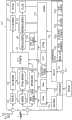
图2为根据实施方式的三维图像处理器的构造图。FIG. 2 is a configuration diagram of a three-dimensional image processor according to an embodiment.
图3为示出了图像能够被识别为三维体的区域(视场)的示意图。FIG. 3 is a schematic diagram showing a region (field of view) where an image can be recognized as a three-dimensional body.
图4为示出了根据实施方式的三维图像处理器的操作的流程图。FIG. 4 is a flowchart showing the operation of the three-dimensional image processor according to the embodiment.
图5为最佳观看位置的说明图。Fig. 5 is an explanatory diagram of the optimum viewing position.
图6A和图6B为显示在显示屏幕上的校准图像的示例。6A and 6B are examples of calibration images displayed on a display screen.
具体实施方式Detailed ways
根据实施方式的三维图像处理装置包括:摄像模块,用于摄取包括显示器前方的区域,所述显示器显示三维图像;以及控制器,用于控制显示器显示摄像模块摄取的图像和三维图像能够被识别为三维体的区域。A three-dimensional image processing device according to an embodiment includes: a camera module for capturing an area including the front of a display that displays a three-dimensional image; and a controller for controlling the display to display the image captured by the camera module and the three-dimensional image can be recognized as The area of the three-dimensional body.
下文中,将参照附图描述实施方式。Hereinafter, embodiments will be described with reference to the drawings.
(实施方式)(implementation mode)
图1为根据实施方式的三维图像处理器(三维图像处理装置)100的示意图。首先,将参照图1对根据实施方式的三维图像处理器100的概要进行描述。三维图像处理器100例如为数字电视。三维图像处理器100通过全景成像系统向用户呈现三维图像,在全景成像系统中,其中具有视差的多个图像(多视角图像)的各像素离散地布置于一个图像中(下文称为合成图像),并且使用双凸透镜控制来自构成合成图像的各像素的光束的轨道以使观察者感知三维图像。FIG. 1 is a schematic diagram of a three-dimensional image processor (three-dimensional image processing device) 100 according to an embodiment. First, an outline of a three-
对于三维图像,已经描述了受限定的视场。当用户位于视场外时,由于逆视、串扰等的产生,使得用户不能将图像识别为三维体。因此,三维图像处理器100被构造为,当用户在遥控器3上按下操作键(校准键)3a时,表示三维图像可被识别为三维体的区域(视场)的框架形导向单元Y叠置于由设置于三维图像处理器100的前面的照相机模块119摄取并显示在显示器113上的图像上。另外,显示器113上还向用户显示“将您的面部对准导向单元”的指令X。For three-dimensional images, a restricted field of view has been described. When the user is located outside the field of view, the user cannot recognize the image as a three-dimensional body due to the occurrence of reverse viewing, crosstalk, and the like. Therefore, the three-
在指令X之后,用户将显示在显示器113上的其面部与导向单元Y的内部对准,从而可易于在适宜的位置观看到三维图像。在以下描述中,通过将表示三维图像可被识别为三维体的区域(视场)的导向单元Y叠置于由设置于三维图像处理器100的前面的照相机模块119摄取的图像上而形成的图像称为校准图像。After instructing X, the user aligns his face displayed on the
(三维图像处理器100的构造)(Configuration of Three-dimensional Image Processor 100)
图2为根据实施方式的三维图像处理器100的构造图。三维图像处理器100包括调谐器101、调谐器102、调谐器103、PSK(相移键控)解调器104、OFDM(正交频分复用)解调器105、模拟解调器106、信号处理模块107、图形处理模块108、OSD(屏幕显示)信号生成模块109、声音处理模块110、扬声器111、图像处理模块112、显示器113、控制器114、操作模块115、光接收模块116(操作接收模块)、端子117、通信I/F(接口)118和照相机模块119。FIG. 2 is a configuration diagram of a three-
调谐器101根据来自控制器114的控制信号,从由用于接收BS/CS数字广播的天线1接收到的卫星数字电视广播中选择期望频道的广播信号。调谐器101将所选广播信号输出至PSK解调器104。PSK解调器104根据来自控制器114的控制信号,对从调谐器101输入的广播信号进行解调,并将解调后的广播信号输出至信号处理模块107。The
调谐器102根据来自控制器114的控制信号,从由用于接收地面广播的天线2接收到的地面数字电视广播信号中选择期望频道的数字广播信号。调谐器102将所选数字广播信号输出至OFDM解调器105。OFDM解调器105根据来自控制器114的控制信号对从调谐器102输入的数字广播信号进行解调,并将解调后的数字广播信号输出至信号处理模块107。The
调谐器103根据来自控制器114的控制信号,从由用于接收地面广播的天线2接收到的地面模拟电视广播信号中选择期望频道的模拟广播信号。调谐器103将所选模拟广播信号输出至模拟解调器106。模拟解调器106根据来自控制器114的控制信号,对从调谐器103输入的模拟广播信号进行解调,并将解调后的模拟广播信号输出至信号处理模块107。The
信号处理模块107根据从PSK解调器104、OFDM解调器105和模拟解调器106输入的解调后的广播信号,生成图像信号和声音信号。信号处理模块107将图像信号输出至图形处理模块108。信号处理模块107进一步将声音信号输出至声音处理模块110。The
OSD信号生成模块109根据来自控制器114的控制信号,生成OSD信号,并将OSD信号输出至图形处理模块108。The OSD
图形处理模块108根据来自控制器114的指令,基于从信号处理模块107输出的图像信号生成多个图像数据(多视角图像数据)。图形处理模块108将生成的多视角图像的各像素离散地布置于一个图像内,以将它们转换为合成图像。图形处理模块108进一步将由OSD信号生成模块109生成的OSD信号输出给图像处理模块112。The
图像处理模块112将由图形处理模块108转换的合成图像转换为可在显示器113上显示的格式,随后将转换的合成图像输出至显示器113,以使其显示三维图像。图像处理模块112将输入的OSD信号转换为可在显示器113上显示的格式,随后将转换的OSD信号输出至显示器113,以使其显示与OSD信号相对应的图像。The
显示器113是用于显示全景成像系统的三维图像的显示器,该全景成像系统包括用于控制来自各像素的光束的轨道的双凸透镜。The
声音处理模块110将输入的声音信号转换为扬声器111可再现的格式,随后将转换的声音信号输出至扬声器111,使其再现声音。The
操作模块115上布置有用于操作三维图像处理器100的多个操作键(例如,光标键、确定(OK)键、BACK(返回)键、颜色键(红、绿、黄、蓝)等)。用户按下上述操作键,由此将与所按下的操作键对应的操作信号输出至控制器114。A plurality of operation keys (for example, cursor keys, OK key, BACK key, color keys (red, green, yellow, blue), etc.) for operating the three-
光接收模块116接收从遥控器3发射的红外信号。遥控器3上布置有用于操作三维图像处理器100的多个操作键(例如,校准键、结束键、光标键、确定键、BACK(返回)键、颜色键(红、绿、黄、蓝)等)。The
用户按下上述操作键,由此发射与所按下的操作键对应的红外信号。光接收模块116接收遥控器3发射的红外信号。光接收模块116将与接收到的红外信号对应的操作信号输出至控制器114。The user presses the operation key, thereby emitting an infrared signal corresponding to the pressed operation key. The
用户可操作操作模块115或遥控器3,以使三维图像处理100进行各种操作。例如,用户可按下遥控器3上的校准键,以在显示器113上显示参照图1描述的校准图像。端子117是用于连接外部终端(例如,USB存储器、DVD存储和再现装置、因特网服务器、PC等)的USB端子、LAN端子、HDMI端子或iLINK端子。The user can operate the
通信I/F 118是用于与端子117连接的上述外部终端的通信接口。通信I/F 118在控制器114和上述外部终端之间转换控制信号和数据格式等。The communication I/
照相机模块119设置于三维图像处理器100的正面上侧或正面下侧。照相机模块119包括摄像元件119a、面部检测模块119b、非易失性存储器119c、同一人判定模块119d和位置计算模块119e。The
摄像元件119a摄取包括三维图像处理器100的前方的区域。摄像元件119a例如为CMOS图像传感器或CCD图像传感器。The imaging element 119 a captures an area including the front of the three-
面部检测模块119b从由摄像元件119a摄取的图像中检测用户面部。面部检测模块119b将摄取的图像分为多个区域。面部检测模块119b对所有分割区域进行面部检测。The
对于面部检测模块119b进行的面部检测,可采用已知方法。例如,可采用对视觉特征与面部检测算法进行直接几何比较的方法。面部检测模块119b将关于检测到的面部的特征点的信息存储于非易失性存储器119c中。For face detection by the
非易失性存储器119c中存储有关于由面部检测模块119b检测到的面部的特征点的信息。In the
同一人判定模块119d判定由面部检测模块119b检测到的面部的特征点是否已经存储在非易失性存储器119c中。在特征点已经存储在非易失性存储器119c中时,同一人判定模块119d判定检测的是同一人。另一方面,在特征点尚未存储在非易失性存储器119c中时,同一人判定模块119d判定检测到其面部的人并非同一人。判定可防止再次向面部检测模块119b已检测的用户显示导向单元Y。The same
在同一人判定模块119d判定已检测到其面部的人并非同一人时,位置计算模块119e根据由面部检测模块119b检测到其面部的用户在图像上的位置(α,β)和摄像元件119a与用户之间的距离γ,计算实际空间中的位置坐标(X,Y,Z)。对于计算实际空间中的位置坐标,可采用已知方法。注意,由照相机110a摄取的图像的左上角被视为原点(0,0),α轴被设为横向方向,β轴被设为纵向方向。对于实际空间中的坐标,显示器113的显示面的中心被视为原点(0,0,0),X轴被设为水平横向方向,Y轴被设为垂直方向,Z轴被设为与显示器113的显示面垂直的方向。When the same
在所摄取的图像中,确定用户上下方向和左右方向的位置(α,β)。进一步,可根据面部右眼和左眼之间的距离,计算摄像元件119a到用户的距离。一般来说,人的右眼和左眼之间的距离为约65mm,因此,如果确定了所摄取图像中右眼和左眼之间的距离,则可算得从摄像元件119a到用户的距离γ。In the captured image, the user's position (α, β) in the up-down direction and in the left-right direction is specified. Further, the distance from the imaging element 119a to the user can be calculated according to the distance between the right eye and the left eye of the face. Generally speaking, the distance between the right eye and the left eye of a person is about 65mm, therefore, if the distance between the right eye and the left eye in the captured image is determined, the distance γ from the imaging element 119a to the user can be calculated .
如果确定了图像上用户的上述位置(α,β)和从摄像元件119a到用户的距离γ,则可计算用户在实际空间中的位置坐标(X,Y,Z)。用户在实际空间中的位置坐标(X,Y,Z)例如可通过根据摄像元件119a的每像素在实际空间中的距离预先获得实际空间中的距离,并将从原点到图像上的用户的像素数量乘以每像素在实际空间中的距离而算得。If the above-mentioned position (α, β) of the user on the image and the distance γ from the imaging element 119a to the user are determined, the position coordinates (X, Y, Z) of the user in real space can be calculated. The user's position coordinates (X, Y, Z) in the actual space, for example, can be obtained in advance according to the distance of each pixel of the imaging element 119a in the actual space, and the distance from the origin to the user's pixel on the image can be obtained in advance. The amount is calculated by multiplying the distance per pixel in real space.
控制器114包括ROM(只读存储器)114a、RAM(随机存取存储器)114b、非易失性存储器114c和CPU 114d。ROM 114a中存储有由CPU 114d执行的控制程序。RAM 114b用作CPU 114d的工作区域。非易失性存储器114c中存储有各种设定信息、视场信息等。视场信息为实际空间中视场的坐标(X,Y,Z)数据。The
图3为非易失性存储器114c中存储的实际空间中的视场坐标(X,Y,Z)的数据的鸟瞰图。在图3中,白色四边形范围201a至201e表示显示器113上显示的图像(三维图像)能够被识别为三维体的区域,即,视场(下文中,四边形范围201a至201e被称为视场201a至201e)。另一方面,对角线区域202是由于所谓的逆视、串扰等的产生(即,处于视场之外),而使得用户不能将图像识别为三维体的区域。FIG. 3 is a bird's-eye view of data of field coordinates (X, Y, Z) in real space stored in the
图3中的虚线203表示摄像元件119a的摄取范围的边界。换句话说,摄像元件119a实际摄取的范围是虚线203下侧的范围。因此,可省略将虚线203的左上范围和和右上范围存储在非易失性存储器114c内。A dotted
控制器114控制整个三维图像处理器100。具体地,控制器114根据从操作模块115和光接收模块116输入的操作信号和非易失性存储器114c中存储的设定信息,控制整个三维图像处理器100的操作。例如,当用户在遥控器3上按下校准键3a时,控制器114在显示器113上显示上述校准图像。The
(三维图像处理器100的操作)(Operation of the three-dimensional image processor 100)
图4为三维图像处理器100的操作的流程图。图5为最佳观看位置的说明图。图6A和图6B为显示器113上显示的校准图像。下文中,将参照图4至图6A和图6B对三维图像处理器100的操作进行描述。FIG. 4 is a flowchart of the operation of the three-
当用户在遥控器3上按下校准键3a时,发射与所按下的校准键3a相对应的红外信号(步骤S101)。光接收模块116接收从遥控器3发射的红外信号。光接收模块116将与所接收到的红外信号相对应的操作信号(校准图像显示信号)输出至控制器114。When the user presses the calibration key 3a on the
在接收到校准图像显示信号后,控制器114指示照相机模块119开始进行摄取。照相机模块119根据来自控制器114的指令,通过摄像元件119a对三维图像处理器100的前方进行摄取(步骤S102)。After receiving the calibration image display signal, the
面部检测模块119b根据由摄像元件119a摄取的图像,进行面部检测(步骤S103)。面部检测模块119b将所摄取的图像分为多个区域,并对所有分割区域进行面部检测。面部检测模块119b将关于检测到的面部的特征点的信息存储于非易失性存储器119c内(步骤S104)。注意,面部检测模块119b对摄像元件119a摄取的图像定期地进行面部检测(例如,每隔几秒至几十秒)。The
同一人判定模块119d判定面部检测模块119b检测到的面部的特征点是否已经存储在非易失性存储器119c中(步骤S105)。当该特征点已经存储在非易失性存储器119c中时(步骤S105中为“是”),照相机模块119返回到步骤S102的操作。The same-
当该特征点尚未存储在非易失性存储器119c中时(步骤S105中为“否”),位置计算模块119e计算面部检测模块119b检测到的面部在实际空间中的位置坐标(X,Y,Z)(步骤S106)。当通过面部检测模块119b检测多个人的面部时,位置计算模块119e计算各个面部在实际空间中的位置坐标(X,Y,Z)。位置计算模块119e将算得的实际空间中的位置坐标(X,Y,Z)输出至控制器114。When the feature point has not been stored in the
当从位置计算模块119e输出位置坐标(X,Y,Z)时,控制器114参考存储在非易失性存储器114c中的视场信息,并推测与位置坐标最近的视场(步骤S107)。When the position coordinates (X, Y, Z) are output from the
将参照图5描述上述操作。在图5所示的示例中,假定在由摄像元件119a摄取的图像中检测到两个用户P1、P2。控制器114推测视场201a至201e中视场201b、201c最靠近两个用户P1、P2的位置坐标(X1,Y1,Z1)、(X2,Y2,Z2)。The above operation will be described with reference to FIG. 5 . In the example shown in FIG. 5 , it is assumed that two users P1 , P2 are detected in the image captured by the imaging element 119 a. The
控制器114获得两个用户P1、P2的Z坐标Z1、Z2的位置处的视场范围。控制器114随后根据所获得的Z坐标Z1、Z2位置处的视场范围,计算摄像元件119a摄取的图像的范围。对于图像范围的计算,可采用已知方法进行。例如,可以根据图像上用户的位置计算用户在实际空间中的位置坐标相反的顺序,计算范围。The
控制器114指示OSD信号生成模块109生成图像信号,以在显示器113上显示校准图像,其中校准图像通过将表示将算得的视场范围的导向单元叠置于摄像元件119a摄取的图像上而形成。OSD信号生成模块109根据来自控制器114的指令,生成校准图像的图像信号。所生成的校准图像的图像信号通过图形处理模块108输出至图像处理模块112。The
图像处理模块112将校准图像的图像信号转换成可在显示器113上显示的格式,并将其输出至显示器113。将校准图像显示在显示器113上(步骤S108)。The
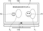
图6A为显示在显示器113上的校准图像。在图6A中,导向单元Y1为图5中用户Y1的导向单元。导向单元Y2为图5中用户Y2的导向单元。用户P1、P2执行显示在显示器113上的指令X,并分别将其面部对准导向单元Y1,Y2的内部。通过将其面部对准导向单元Y1,Y2的内部,用户P1、P2可在适宜的位置(即,不会发生逆视、串扰等的视场内部)观看到三维图像。注意,导向单元Y1、Y2被显示在与用户P1、P2的检测面部的高度基本相同的高度。视场在纵向方向(X坐标方向)几乎无变化。因此,如果导向单元Y1、Y2显示在与用户P1、P2的检测面部的高度基本相同的高度,则观看到三维图像不会存在问题。FIG. 6A is a calibration image displayed on the
在图6A所示的校准图像中,可能会出现用户P1、P2不太清楚他们应将其面部分别对准哪个导向单元Y1,Y2的情况。这种情况下,如图6B所示,可另外显示箭头Z1、Z2,以方便用户P1、P2知道他们分别应将其面部对准哪个导向单元Y1、Y2。当检测到多个用户时,导向单元Y1、Y2的形状和颜色可以变化(例如,导向单元Y1用矩形表示,导向单元Y2用卵形表示)。导向单元(框架)Y可用实线表示。进一步,尽管导向单元Y1、Y2用框架表示,但并不限于框架,只要用户可识别他们,可采用另一种显示方法呈现。In the calibration image shown in FIG. 6A , it may happen that the users P1 , P2 are not quite clear which guide unit Y1 , Y2 they should aim their faces at, respectively. In this case, as shown in FIG. 6B , arrows Z1 , Z2 may be additionally displayed, so that users P1 , P2 know which guide unit Y1 , Y2 they should aim their faces at, respectively. When multiple users are detected, the shape and color of the guide units Y1 , Y2 may change (for example, the guide unit Y1 is represented by a rectangle, and the guide unit Y2 is represented by an oval shape). The guide unit (frame) Y can be represented by a solid line. Further, although the guide units Y1 , Y2 are represented by frames, they are not limited to frames, and may be presented by another display method as long as the user can recognize them.
在将图6A、图6B所示的校准图像显示之后,控制器114判定用户按下遥控器3上的校准键3a还是结束键(步骤S109)。可通过在控制器114接收到与遥控器3上的校准键3a或结束键的按下相对应的操作信号而进行该判定。After displaying the calibration images shown in FIGS. 6A and 6B , the
当按下校准键3a或结束键时(步骤S109中为“是”),控制器114指示OSD信号生成模块109结束校准图像的显示,操作随之结束。When the calibration key 3a or the end key is pressed (YES in step S109), the
如上所述,根据实施方式的三维图像处理器100包括摄像元件119a,其摄取包括三维图像处理器100的前方的区域。三维图像处理器100在从照相机摄取的图像中检测用户,并在显示器113上显示校准图像,该校准图像通过将表示最靠近检测到的用户位置的视场的导向单元叠置于由摄像元件119a摄取的图像上而形成。As described above, the three-
用户仅需将其面部对准显示器113上显示的导向单元的内部,便能够在适宜的位置(即,不会发生逆视、串扰等的视场内部)观看到三维图像。进一步,仅需在遥控器3上按下校准键3a,便可在显示器113上显示校准图像,这对用户来说是非常方便的。The user only needs to align his face with the inside of the guide unit displayed on the
进一步,由于呈现距用户的位置最近的视场,所以用户移动小的移动量便可到用于观看三维图像的适宜位置,从而为用户提高了便利性。进一步,即使存在多个用户,也会为各个用户显示导向单元。另外,当为用户显示导向单元(箭头),以使其知道分别应将其面部对准哪个导向单元时,用户可容易地知晓他们应该将其面部分别对准哪个导向单元,从而进一步为用户提高便利性。Further, since the field of view closest to the user's position is presented, the user can move to a suitable position for viewing a three-dimensional image with a small amount of movement, thereby improving convenience for the user. Further, even if there are multiple users, guide elements are displayed for each user. In addition, when the guide units (arrows) are displayed for users so that they know which guide units they should respectively align their faces with, the users can easily know which guide units they should respectively align their faces with, thereby further improving the user experience. convenience.
另外,设置同一人判定模块119d以用于判定面部检测模块119b检测的面部的特征点是否已经存储在非易失性存储器119c中。在特征点已经存储在非易失性存储器119c中时,位置计算模块119e不计算该用户的位置。因此,可防止再次为已检测到的用户显示导向单元Y。In addition, the same
(其他实施方式)(Other implementations)
尽管已经描述了一些实施方式,但这些实施方式仅以示例的方式提供,并且并不意旨限制本发明的范围。实际上,本文中所描述的新颖的实施方式可以是各种其他形式的实施方式;此外,在不背离本发明的精神的前提下,可以对本文中所描述的实施方式的形式进行替换和改变。附图及其等价物意旨涵盖这些形式或修改,并且这些形式和修改落在本发明的精神和范围内。While some embodiments have been described, these embodiments have been presented by way of example only, and are not intended to limit the scope of the inventions. In fact, the novel embodiments described herein may be implemented in various other forms; moreover, substitutions and changes may be made to the forms of the embodiments described herein without departing from the spirit of the present invention. . The drawings and their equivalents are intended to cover such forms or modifications as fall within the spirit and scope of the invention.
尽管在上述实施方式中,例如将数字电视作为示例描述了三维图像处理器100,但本发明可应用于为用户呈现三维图像的任何装置(例如,PC(个人计算机)、蜂窝电话、平板PC、游戏机等);以及向呈现三维图像的显示器输出图像信号的信号处理器(例如,STB(机顶盒))。Although in the above-mentioned embodiments, the three-
进一步,照相机模块119中所包含的面部检测模块119b、同一人判定模块119d和位置计算模块119e的功能可设置在控制器114内。在这种情况下,控制器114将根据由摄像元件119a摄取的图像检测用户面部;判定被检测用户是否是已被检测的人员,并计算用户位置。Further, the functions of the
Claims (9)
Translated fromChineseApplications Claiming Priority (2)
| Application Number | Priority Date | Filing Date | Title |
|---|---|---|---|
| JP2011186944AJP5143262B1 (en) | 2011-08-30 | 2011-08-30 | 3D image processing apparatus and 3D image processing method |
| JP2011-186944 | 2011-08-30 |
Publications (1)
| Publication Number | Publication Date |
|---|---|
| CN102970560Atrue CN102970560A (en) | 2013-03-13 |
Family
ID=47742912
Family Applications (1)
| Application Number | Title | Priority Date | Filing Date |
|---|---|---|---|
| CN2012100689763APendingCN102970560A (en) | 2011-08-30 | 2012-03-15 | Three-dimensional image processing apparatus and three-dimensional image processing method |
Country Status (3)
| Country | Link |
|---|---|
| US (1) | US20130050071A1 (en) |
| JP (1) | JP5143262B1 (en) |
| CN (1) | CN102970560A (en) |
Citations (4)
| Publication number | Priority date | Publication date | Assignee | Title |
|---|---|---|---|---|
| JP2005223495A (en)* | 2004-02-04 | 2005-08-18 | Sharp Corp | 3D image display apparatus and method |
| JP2006197373A (en)* | 2005-01-14 | 2006-07-27 | Mitsubishi Electric Corp | Viewer information measuring device |
| JP2011049630A (en)* | 2009-08-25 | 2011-03-10 | Canon Inc | 3d image processing apparatus and control method thereof |
| CN102056003A (en)* | 2009-11-04 | 2011-05-11 | 三星电子株式会社 | High-density multi-viewpoint image display system and method using active sub-pixel rendering |
Family Cites Families (20)
| Publication number | Priority date | Publication date | Assignee | Title |
|---|---|---|---|---|
| US6640004B2 (en)* | 1995-07-28 | 2003-10-28 | Canon Kabushiki Kaisha | Image sensing and image processing apparatuses |
| JPH10174127A (en)* | 1996-12-13 | 1998-06-26 | Sanyo Electric Co Ltd | Method and device for three-dimensional display |
| JP3443271B2 (en)* | 1997-03-24 | 2003-09-02 | 三洋電機株式会社 | 3D image display device |
| US6466185B2 (en)* | 1998-04-20 | 2002-10-15 | Alan Sullivan | Multi-planar volumetric display system and method of operation using psychological vision cues |
| GB2341231A (en)* | 1998-09-05 | 2000-03-08 | Sharp Kk | Face detection in an image |
| JP2001095014A (en)* | 1999-09-24 | 2001-04-06 | Sanyo Electric Co Ltd | Position detector and head position followup type stereoscopic display using the same |
| JP3469884B2 (en)* | 2001-03-29 | 2003-11-25 | 三洋電機株式会社 | 3D image display device |
| JP2004213355A (en)* | 2002-12-27 | 2004-07-29 | Canon Inc | Information processing method |
| WO2004081855A1 (en)* | 2003-03-06 | 2004-09-23 | Animetrics, Inc. | Generation of image databases for multifeatured objects |
| JP4830650B2 (en)* | 2005-07-05 | 2011-12-07 | オムロン株式会社 | Tracking device |
| JP4595750B2 (en)* | 2005-08-29 | 2010-12-08 | ソニー株式会社 | Image processing apparatus and method, and program |
| JP2007081562A (en)* | 2005-09-12 | 2007-03-29 | Toshiba Corp | Stereoscopic image display device, stereoscopic image display program, and stereoscopic image display method |
| JP2008199514A (en)* | 2007-02-15 | 2008-08-28 | Fujifilm Corp | Image display device |
| JP5322264B2 (en)* | 2008-04-01 | 2013-10-23 | Necカシオモバイルコミュニケーションズ株式会社 | Image display apparatus and program |
| JP4697279B2 (en)* | 2008-09-12 | 2011-06-08 | ソニー株式会社 | Image display device and detection method |
| US8732623B2 (en)* | 2009-02-17 | 2014-05-20 | Microsoft Corporation | Web cam based user interaction |
| US8467133B2 (en)* | 2010-02-28 | 2013-06-18 | Osterhout Group, Inc. | See-through display with an optical assembly including a wedge-shaped illumination system |
| JP5425305B2 (en)* | 2010-05-31 | 2014-02-26 | 富士フイルム株式会社 | Stereoscopic image control apparatus, operation control method thereof, and operation control program thereof |
| US8576276B2 (en)* | 2010-11-18 | 2013-11-05 | Microsoft Corporation | Head-mounted display device which provides surround video |
| US9118833B2 (en)* | 2010-11-29 | 2015-08-25 | Fotonation Limited | Portrait image synthesis from multiple images captured on a handheld device |
- 2011
- 2011-08-30JPJP2011186944Apatent/JP5143262B1/ennot_activeExpired - Fee Related
- 2012
- 2012-03-01USUS13/410,010patent/US20130050071A1/ennot_activeAbandoned
- 2012-03-15CNCN2012100689763Apatent/CN102970560A/enactivePending
Patent Citations (4)
| Publication number | Priority date | Publication date | Assignee | Title |
|---|---|---|---|---|
| JP2005223495A (en)* | 2004-02-04 | 2005-08-18 | Sharp Corp | 3D image display apparatus and method |
| JP2006197373A (en)* | 2005-01-14 | 2006-07-27 | Mitsubishi Electric Corp | Viewer information measuring device |
| JP2011049630A (en)* | 2009-08-25 | 2011-03-10 | Canon Inc | 3d image processing apparatus and control method thereof |
| CN102056003A (en)* | 2009-11-04 | 2011-05-11 | 三星电子株式会社 | High-density multi-viewpoint image display system and method using active sub-pixel rendering |
Also Published As
| Publication number | Publication date |
|---|---|
| JP2013051469A (en) | 2013-03-14 |
| JP5143262B1 (en) | 2013-02-13 |
| US20130050071A1 (en) | 2013-02-28 |
Similar Documents
| Publication | Publication Date | Title |
|---|---|---|
| CN103096103A (en) | Video processing device and video processing method | |
| US20120050502A1 (en) | Image-processing method for a display device which outputs three-dimensional content, and display device adopting the method | |
| US8477181B2 (en) | Video processing apparatus and video processing method | |
| US8749617B2 (en) | Display apparatus, method for providing 3D image applied to the same, and system for providing 3D image | |
| US9418436B2 (en) | Image processing apparatus, imaging apparatus, and image processing method | |
| JP5197816B2 (en) | Electronic device, control method of electronic device | |
| JP5134714B1 (en) | Video processing device | |
| JP2007212664A (en) | Liquid crystal display device | |
| US9118903B2 (en) | Device and method for 2D to 3D conversion | |
| CN102970561B (en) | Video processing apparatus and video processing method | |
| CN103517056A (en) | Detector, detection method and video display apparatus | |
| US20120002010A1 (en) | Image processing apparatus, image processing program, and image processing method | |
| CN102970567B (en) | Video processing apparatus and video processing method | |
| KR20130033815A (en) | Image display apparatus, and method for operating the same | |
| WO2012120880A1 (en) | 3d image output device and 3d image output method | |
| KR20120054746A (en) | Method and apparatus for generating three dimensional image in portable communication system | |
| KR101867815B1 (en) | Apparatus for displaying a 3-dimensional image and method for adjusting viewing distance of 3-dimensional image | |
| CN102970560A (en) | Three-dimensional image processing apparatus and three-dimensional image processing method | |
| JP5433763B2 (en) | Video processing apparatus and video processing method | |
| JP5127972B1 (en) | Electronic device, control method of electronic device | |
| JP2013059094A (en) | Three-dimensional image processing apparatus and three-dimensional image processing method | |
| TWI502960B (en) | Device and method for 2d to 3d conversion | |
| JP2013070153A (en) | Imaging apparatus | |
| KR20130020209A (en) | Apparatus for processing a 3-dimensional image and method for changing an image mode of the same | |
| JP5433766B2 (en) | Video processing apparatus and video processing method |
Legal Events
| Date | Code | Title | Description |
|---|---|---|---|
| C06 | Publication | ||
| PB01 | Publication | ||
| C10 | Entry into substantive examination | ||
| SE01 | Entry into force of request for substantive examination | ||
| C02 | Deemed withdrawal of patent application after publication (patent law 2001) | ||
| WD01 | Invention patent application deemed withdrawn after publication | Application publication date:20130313 |