CN102969732A - Mixed bipolar direct current (DC) transmission system - Google Patents
Mixed bipolar direct current (DC) transmission systemDownload PDFInfo
- Publication number
- CN102969732A CN102969732ACN2012104316521ACN201210431652ACN102969732ACN 102969732 ACN102969732 ACN 102969732ACN 2012104316521 ACN2012104316521 ACN 2012104316521ACN 201210431652 ACN201210431652 ACN 201210431652ACN 102969732 ACN102969732 ACN 102969732A
- Authority
- CN
- China
- Prior art keywords
- direct current
- power
- series
- current transmission
- transmission system
- Prior art date
- Legal status (The legal status is an assumption and is not a legal conclusion. Google has not performed a legal analysis and makes no representation as to the accuracy of the status listed.)
- Granted
Links
- 230000005540biological transmissionEffects0.000titleclaimsabstractdescription80
- 239000003990capacitorSubstances0.000claimsdescription11
- 238000009499grossingMethods0.000claimsdescription9
- 238000004804windingMethods0.000claimsdescription8
- 238000010586diagramMethods0.000description14
- 238000000034methodMethods0.000description8
- 230000007547defectEffects0.000description5
- 238000006243chemical reactionMethods0.000description2
- 238000004140cleaningMethods0.000description2
- 238000011217control strategyMethods0.000description2
- 238000004088simulationMethods0.000description2
- 230000000903blocking effectEffects0.000description1
- 238000010276constructionMethods0.000description1
- 230000003247decreasing effectEffects0.000description1
- 230000000694effectsEffects0.000description1
- 230000008030eliminationEffects0.000description1
- 238000003379elimination reactionMethods0.000description1
- 238000005516engineering processMethods0.000description1
- 238000010304firingMethods0.000description1
- 238000009413insulationMethods0.000description1
- 238000002955isolationMethods0.000description1
- 230000010363phase shiftEffects0.000description1
- 239000004065semiconductorSubstances0.000description1
- 230000035939shockEffects0.000description1
- 230000001052transient effectEffects0.000description1
- 238000013024troubleshootingMethods0.000description1
- 239000002699waste materialSubstances0.000description1
Images


Classifications
- Y—GENERAL TAGGING OF NEW TECHNOLOGICAL DEVELOPMENTS; GENERAL TAGGING OF CROSS-SECTIONAL TECHNOLOGIES SPANNING OVER SEVERAL SECTIONS OF THE IPC; TECHNICAL SUBJECTS COVERED BY FORMER USPC CROSS-REFERENCE ART COLLECTIONS [XRACs] AND DIGESTS
- Y02—TECHNOLOGIES OR APPLICATIONS FOR MITIGATION OR ADAPTATION AGAINST CLIMATE CHANGE
- Y02E—REDUCTION OF GREENHOUSE GAS [GHG] EMISSIONS, RELATED TO ENERGY GENERATION, TRANSMISSION OR DISTRIBUTION
- Y02E60/00—Enabling technologies; Technologies with a potential or indirect contribution to GHG emissions mitigation
- Y02E60/60—Arrangements for transfer of electric power between AC networks or generators via a high voltage DC link [HVCD]
Landscapes
- Inverter Devices (AREA)
- Rectifiers (AREA)
Abstract
Translated fromChineseDescription
Translated fromChinese技术领域technical field
本发明属于电力系统输电技术领域,具体涉及一种混合双极直流输电系统。The invention belongs to the technical field of electric power system transmission, and in particular relates to a hybrid bipolar direct current transmission system.
背景技术Background technique
随着电力科学技术的发展,基于晶闸管换流器的传统高压直流输电系统的造价逐年降低,电力输送的可靠性不断提高,站内损耗渐渐减小。目前,基于晶闸管换流器的传统高压直流输电系统已经被广泛应用于大容量远距离输电、海岛输电以及异步电网背靠背互联等场合。但是,基于晶闸管换流器的传统高压直流输电系统有以下三个主要的缺陷:(1)逆变侧易换相失败;由于晶闸管换流器的主要器件晶闸管属于半控型器件,其换相方式采用电网换相,因此交流电网的波动或者故障有可能导致逆变侧的晶闸管换流器出现换相失败,这将造成交流系统的巨大冲击,严重地影响系统稳定安全运行。(2)对交流系统的依赖性强;基于晶闸管换流器的传统高压直流输电系统无法对弱交流系统以及无源网络进行输电;(3)换流站占地面积大;因此直流落点的选址上存在着较大的问题,对于发达的东南沿海地区,修建一座基于晶闸管的传统高压直流换流站会造成较大的土地资源浪费。综上所述,基于晶闸管换流器的传统高压直流输电系统存在着的较大的缺陷,一定程度上制约了它的发展。With the development of electric power science and technology, the cost of traditional high-voltage DC transmission systems based on thyristor converters has been reduced year by year, the reliability of power transmission has been continuously improved, and the losses in stations have gradually decreased. At present, the traditional HVDC power transmission system based on thyristor converters has been widely used in large-capacity long-distance power transmission, island power transmission, and back-to-back interconnection of asynchronous grids. However, the traditional HVDC power transmission system based on the thyristor converter has the following three main defects: (1) The inverter side is prone to commutation failure; since the thyristor, the main component of the thyristor converter, is a semi-controlled device, its The grid commutation method is adopted, so the fluctuation or failure of the AC grid may cause the commutation failure of the thyristor converter on the inverter side, which will cause a huge impact on the AC system and seriously affect the stable and safe operation of the system. (2) Strong dependence on the AC system; traditional HVDC power transmission systems based on thyristor converters cannot transmit power to weak AC systems and passive networks; (3) The converter station occupies a large area; There are big problems in site selection. For the developed southeastern coastal areas, building a traditional thyristor-based HVDC converter station will cause a lot of waste of land resources. To sum up, the traditional high-voltage DC transmission system based on thyristor converters has relatively large defects, which restrict its development to a certain extent.
基于模块化多电平换流器(Modular Multilevel Converter,MMC)的直流输电系统是一种较为新颖的柔性直流输电系统,其拓扑结构的基本单元是半桥子模块。相较于基于晶闸管换流器的传统高压直流输电系统,模块化多电平换流器直流输电系统有着诸多优点,例如能够实现有功功率及无功功率解耦控制、开关频率低、运行损耗低、输出电压波形谐波系数低、滤波系统成本低廉、拓展性强、结构紧凑占地面积小、不存在换相失败故障等等。在光伏、风电和潮汐等新能源并网,超大规模城市输配电,偏远海岛、孤立负荷以及无源网络供电等应用场合,模块化多电平换流器直流输电系统有着很强的竞争力。然而,模块化多电平换流器直流输电系统同样也存在两个较大的缺陷:(1)无法有效的处理直流侧的故障,系统可靠性低。当直流侧发生故障时,全控型开关器所反向并联的蓄流二极管会造成能量馈送点与故障点之间的能量馈送回路,这会造成瞬时的过电流,因此必须跳开交流断路器将其切断,但交流断路器的机械响应时间最快也需要2~3个周波,而短路过电流在这2~3个周波的时间内已经增大到较大的数值;因此在选择设备时不得不增大设备的额定参数,并且配置高速的旁路开关等辅助性措施;这大大地增加了换流站的建造成本;而且,模块化多电平换流器直流输电系统常常需要使用故障率低、造价高的电缆线路作为其直流输电线路,而无法使用闪络等暂时性故障率高、造价低的架空线路输电,这导致了其无法应用于长距离直流输电场合。(2)接地支路设计、安装困难。目前采用的接地方式主要有两种:一是在模块多电平换流器的交流侧安装三相星形连接的电抗支路为换流站提供参考电位,但是电抗参数选择较为困难,并且会对换流器本身的无功功率的运行范围造成影响;二是采用直流侧大电阻嵌位接地方式,但是大电阻参数的选取较为困难,当电阻取得过小则稳态运行时的损耗会增大,当电阻取得过大则失去了接地的意义。综上所述,基于模块化多电平换流器直流输电系统存在着的较大的缺陷,一定程度上制约了它的发展。The DC transmission system based on Modular Multilevel Converter (MMC) is a relatively novel flexible DC transmission system, and the basic unit of its topology is the half-bridge sub-module. Compared with the traditional high-voltage DC transmission system based on thyristor converters, the modular multilevel converter DC transmission system has many advantages, such as decoupling control of active power and reactive power, low switching frequency, and low operating loss. , The harmonic coefficient of the output voltage waveform is low, the cost of the filter system is low, the expandability is strong, the structure is compact and the floor area is small, there is no failure of commutation, etc. In applications such as photovoltaic, wind power, tidal and other new energy grid-connected, ultra-large-scale urban power transmission and distribution, remote islands, isolated loads, and passive network power supply, the modular multi-level converter DC transmission system has a strong competitiveness . However, the modular multi-level converter direct current transmission system also has two major defects: (1) it cannot effectively deal with faults on the direct current side, and the system reliability is low. When a fault occurs on the DC side, the anti-parallel current storage diode of the fully-controlled switch will cause an energy feed loop between the energy feed point and the fault point, which will cause an instantaneous overcurrent, so the AC circuit breaker must be tripped Cut it off, but the fastest mechanical response time of the AC circuit breaker also needs 2 to 3 cycles, and the short-circuit overcurrent has increased to a larger value within the time of 2 to 3 cycles; therefore, when selecting equipment It is necessary to increase the rated parameters of the equipment and configure auxiliary measures such as high-speed bypass switches; this greatly increases the construction cost of the converter station; moreover, the modular multilevel converter DC transmission system often needs to use fault The cable line with low rate and high cost is used as its DC transmission line, and overhead lines with high temporary failure rate and low cost such as flashover cannot be used for power transmission, which makes it unable to be applied to long-distance DC transmission occasions. (2) It is difficult to design and install the grounding branch circuit. There are two main grounding methods currently used: one is to install a three-phase star-connected reactance branch on the AC side of the modular multilevel converter to provide a reference potential for the converter station, but the choice of reactance parameters is difficult and will It affects the operating range of the reactive power of the converter itself; the second is to adopt the clamping grounding method of large resistance on the DC side, but the selection of large resistance parameters is relatively difficult. When the resistance is too small, the loss during steady-state operation will increase. Large, when the resistance is too large, it loses the meaning of grounding. To sum up, there are major defects in the DC transmission system based on modular multilevel converters, which restrict its development to a certain extent.
发明内容Contents of the invention
针对现有技术所存在的上述技术缺陷,本发明提供了一种混合双极直流输电系统,结合了基于晶闸管换流器以及基于MMC的直流输电拓扑的优点;解决了逆变侧换相失败及直流侧无法自清理故障等技术问题,占地面积小,接地方式设计简易。Aiming at the above-mentioned technical defects existing in the prior art, the present invention provides a hybrid bipolar direct current transmission system, which combines the advantages of the thyristor-based converter and the MMC-based direct current transmission topology; solves the commutation failure on the inverter side and the The DC side cannot self-clean faults and other technical problems, the floor space is small, and the grounding method is easy to design.
一种混合双极直流输电系统,包括:整流换流站和逆变换流站,两者通过直流输电线路相连;其中:A hybrid bipolar direct current transmission system, including: a rectification converter station and an inverter converter station, both of which are connected through a direct current transmission line; wherein:
所述的整流换流站用于将送端交流电网的三相交流电转换为直流电后通过直流输电线路传送给逆变换流站;整流换流站由两台晶闸管换流器串联组成,其串联节点接地;The rectification converter station is used to convert the three-phase alternating current of the sending end AC power grid into direct current and transmit it to the inverter converter station through the DC transmission line; the rectification converter station is composed of two thyristor converters in series, and its series node grounding;
所述的逆变换流站用于将所述的直流电转换为三相交流电后输送给受端交流电网;逆变换流站由两台MMC串联组成,其串联节点接地,串联后的正负两端均连接有单向导通功率器件。The inverter converter station is used to convert the direct current into three-phase alternating current and then transmit it to the AC power grid at the receiving end; the inverter converter station is composed of two MMCs connected in series, the series nodes of which are grounded, and the positive and negative terminals after series connection Both are connected with unidirectional conduction power devices.
所述的单向导通功率器件由若干个二极管或晶闸管串联构成。The unidirectional conduction power device is composed of several diodes or thyristors connected in series.
优选地,所述的送端交流电网进站(整流换流站)的三相母线上连接有无源滤波器;其用于滤除交流侧的电压谐波,提供一定的无功补偿。Preferably, a passive filter is connected to the three-phase bus of the incoming AC power grid at the sending end (rectification and conversion station); it is used to filter out voltage harmonics on the AC side and provide certain reactive power compensation.
优选地,所述的整流换流站正负两端均通过平波电抗器与直流输电线路相连接;所述的逆变换流站正负两端连接的两个单向导通功率器件均通过平波电抗器与直流输电线路相连接;能够对直流电流中的纹波进行平抑,防止直流输电线路产生的陡波前冲击波进入换流站导致器件遭受过电压而损坏,同时避免电流断续。Preferably, the positive and negative ends of the rectification converter station are connected to the direct current transmission line through smoothing reactors; the two unidirectional conduction power devices connected to the positive and negative ends of the inverter The wave reactor is connected with the DC transmission line; it can stabilize the ripple in the DC current, prevent the steep front shock wave generated by the DC transmission line from entering the converter station and cause the device to be damaged by overvoltage, and at the same time avoid current interruption.
优选地,所述的晶闸管换流器采用十二脉动桥式结构,每个桥臂均由若干个晶闸管串联组成;十二脉动桥式晶闸管换流器可减少自身所产生的谐波电流。Preferably, the thyristor converter adopts a twelve-pulse bridge structure, and each bridge arm is composed of several thyristors in series; the twelve-pulse bridge thyristor converter can reduce the harmonic current generated by itself.
优选地,所述的晶闸管换流器通过一台接线方式为Y0/Y/Δ的三绕组变压器或两台接线方式分别为Y0/Δ和Y0/Y的双绕组变压器与送端交流电网连接;能够起到电压等级变换和隔离零序分量在换流器与交流系统之间传递的作用,且这样的变压器能为晶闸管换流器的上下两个六脉动换流桥提供相角差为30°的三相交流电。Preferably, the thyristor converter communicates with the sending end through a three-winding transformer with a connection mode of Y0 /Y/Δ or two double-winding transformers with a connection mode of Y0 /Δ and Y0 /Y respectively. Grid connection; it can play the role of voltage level conversion and isolation of zero-sequence components transmitted between the converter and the AC system, and such a transformer can provide phase angle difference for the upper and lower two six-pulse converter bridges of the thyristor converter Three-phase alternating current at 30°.
优选地,所述的MMC通过接线方式为Δ/Y0或Y/Y0的双绕组变压器与受端交流电网连接,其采用三相六桥臂结构,每个桥臂均由若干个换流模块串联组成;其输出的三相交流电具有很小的谐波含量,几乎不需任何滤波器,同时其结构特性大大降低了器件的开关频率,进而减少损耗,控制灵活。Preferably, the MMC is connected to the AC power grid at the receiving end through a double-winding transformer with a connection mode of Δ/Y0 or Y/Y0 , which adopts a three-phase six-leg structure, and each bridge arm is composed of several commutation The modules are connected in series; the output three-phase alternating current has very small harmonic content, almost no filter is needed, and its structural characteristics greatly reduce the switching frequency of the device, thereby reducing losses and enabling flexible control.
进一步优选地,所述的换流模块采用HBSM(半桥子模块);所需半导体器件数量最少,稳态运行损耗小。Further preferably, the converter module adopts HBSM (half-bridge sub-module); the required number of semiconductor devices is the least, and the steady-state operation loss is small.
所述的HBSM由两个开关管T1~T2和一个电容C构成;其中,开关管T1的输出端与开关管T2的输入端相连并构成HBSM的一端,开关管T1的输入端和电容C的一端相连,开关管T2的输出端与电容C的另一端相连并构成HBSM的另一端;所述的开关管的控制端接收外部设备提供的开关信号。The HBSM is composed of two switching tubes T1-T2 and a capacitor C; wherein, the output end of the switching tube T1 is connected to the input end of the switching tube T2 and constitutes one end of the HBSM, the input end of the switching tube T1 and the capacitor C One end is connected, and the output end of the switch tube T2 is connected with the other end of the capacitor C to form the other end of the HBSM; the control end of the switch tube receives a switch signal provided by an external device.
所述的开关管采用IGBT(绝缘栅双极型晶体管)。The switch tube adopts IGBT (Insulated Gate Bipolar Transistor).
本发明在正常工作时,两台正负极晶闸管换流器通过控制晶闸管触发角的大小来调整直流侧电压的大小,通过整流换流站将三相交流电转变为直流电;两台正负极MMC实现有功无功解耦控制,能够灵活控制有功功率与无功功率;直流电流从整流换流站的正端流出,经过平波电抗器的平抑作用使得直流电流变得平滑,通过正极直流输电线路的输送,直流电流经正极单向导通功率器件后注入正极MMC的正端,并从其负端流出;从正极MMC流出的电流流入负极MMC的正端,再从其负端流出;电流经过负极单向导通功率器件和平波电抗器,通过负极直流输电线路流入整流换流站的负端。When the present invention works normally, the two positive and negative thyristor converters adjust the size of the DC side voltage by controlling the trigger angle of the thyristors, and convert the three-phase alternating current into direct current through the rectification converter station; the two positive and negative pole MMCs Realize active and reactive power decoupling control, and can flexibly control active power and reactive power; DC current flows out from the positive terminal of the rectification converter station, smoothes the DC current through the smoothing reactor, and passes through the positive DC transmission line The transmission of DC current is injected into the positive end of the positive MMC through the positive one-way conduction power device, and flows out from its negative end; the current flowing out from the positive MMC flows into the positive end of the negative MMC, and then flows out from its negative end; the current flows through the negative end The unidirectional conduction power device and the smoothing reactor flow into the negative terminal of the rectifier station through the negative DC transmission line.
在直流线路发生单极直流故障时,故障极整流侧晶闸管换流器闭锁,则故障极整流侧输出的直流电流降为零,即不会产生直流故障的过电流。故障极逆变侧由于具有单向导通能力的大功率器件反向截止的作用,截断了逆变侧交流系统与故障点之间的能量馈路,亦不会产生直流故障的过电流。此时系统由正常运行模式切换到单极运行模式。When a unipolar DC fault occurs on the DC line, the thyristor converter on the rectification side of the faulty pole is blocked, and the output DC current on the rectification side of the faulty pole drops to zero, that is, no overcurrent of the DC fault occurs. On the inverter side of the fault pole, due to the reverse cut-off function of the high-power device with unidirectional conduction capability, the energy feed between the AC system on the inverter side and the fault point is cut off, and the overcurrent of the DC fault will not be generated. At this time, the system switches from normal operation mode to unipolar operation mode.
在直流线路发生双极直流故障时,整流侧晶闸管换流器全部闭锁,则整流侧输出的直流电流下降为零,即不会产生直流故障的过电流。逆变侧由于具有单向导通能力的大功率器件反向截止的作用,截断了逆变侧交流系统与故障点之间的能量馈路,亦不会产生直流故障的过电流。此时直流输电系统所连接的两端交流系统不再有能量交换,直流系统进入运行重启动的等待模式。When a bipolar DC fault occurs on the DC line, all thyristor converters on the rectification side are blocked, and the output DC current on the rectification side drops to zero, that is, no overcurrent due to DC faults will occur. Due to the reverse cut-off function of high-power devices with unidirectional conduction capability, the inverter side cuts off the energy feed between the AC system on the inverter side and the fault point, and does not generate overcurrent of DC faults. At this time, the AC systems at both ends connected to the DC transmission system no longer have energy exchange, and the DC system enters the waiting mode for operation restart.
本发明相对于传统基于晶闸管换流器的直流输电系统,由于受端逆变侧采用模块化多电平换流器,从根本上解决了传统直流输电系统逆变侧换相失败、对交流系统依赖性强以及逆变站占地空间大、滤波器设计等问题,且适用于向多直流落点区域、无源网络或弱交流系统供电等场合。相对于传统基于模块化多电平柔性高压直流输电系统,由于送端整流侧使用晶闸管的十二脉动桥式换流器,控制方便,可以大大减少造价不菲的全控器件数量,节约了成本,降低了损耗,可靠性高,控制灵活。Compared with the traditional DC power transmission system based on the thyristor converter, the invention fundamentally solves the problem of phase commutation failure on the inverter side of the traditional DC power transmission system and the impact on the AC system due to the use of a modular multi-level converter on the inverter side of the receiving end. Strong dependence, large space occupied by the inverter station, filter design and other issues, and it is suitable for power supply to areas with multiple DC drop points, passive networks or weak AC systems. Compared with the traditional modular multi-level flexible HVDC power transmission system, the 12-pulse bridge converter with thyristors is used on the rectification side at the sending end, which is easy to control and can greatly reduce the number of costly full-control devices and save costs. , Reduced loss, high reliability, flexible control.
本发明系统分为正负两极系统,双极运行大大提升了直流输电系统的稳定运行能力,接地方式设计简易;且创新性地在逆变侧换流站的正负极直流端口处加设具有单向导通能力的功率器件,能够起到直流线路故障自清理的作用,使得系统能够应用于远距离、大功率的直流输电领域,具有广阔的应用前景,值得大力推广。The system of the present invention is divided into a positive and negative two-pole system. The bipolar operation greatly improves the stable operation capability of the DC transmission system, and the grounding method is easy to design; The power device with unidirectional conduction capability can play the role of self-cleaning of DC line faults, so that the system can be applied to the field of long-distance and high-power DC transmission. It has broad application prospects and is worthy of vigorous promotion.
附图说明Description of drawings
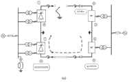
图1为本发明直流输电系统的结构示意图。Fig. 1 is a schematic structural diagram of a direct current transmission system of the present invention.
图2为晶闸管换流器的结构示意图。Fig. 2 is a schematic structural diagram of a thyristor converter.
图3为MMC的结构示意图。Fig. 3 is a schematic diagram of the structure of MMC.
图4为HBSM的结构示意图。Figure 4 is a schematic diagram of the structure of the HBSM.
图5(a)为正极功率与负极功率相同时本发明系统运行示意图。Fig. 5(a) is a schematic diagram of the operation of the system of the present invention when the power of the positive pole and the power of the negative pole are the same.
图5(b)为正极功率大于负极功率时本发明系统运行示意图。Fig. 5(b) is a schematic diagram of the operation of the system of the present invention when the positive electrode power is greater than the negative electrode power.
图5(c)为正极功率小于负极功率时本发明系统运行示意图。Fig. 5(c) is a schematic diagram of the operation of the system of the present invention when the power of the positive electrode is smaller than the power of the negative electrode.
图6(a)为正极输电线路发生直流故障时本发明系统运行示意图。Fig. 6(a) is a schematic diagram of the operation of the system of the present invention when a DC fault occurs on the positive transmission line.
图6(b)为负极输电线路发生直流故障时本发明系统运行示意图。Fig. 6(b) is a schematic diagram of the operation of the system of the present invention when a DC fault occurs on the negative power transmission line.
图6(c)为双极输电线路发生直流故障时本发明系统运行示意图。Fig. 6(c) is a schematic diagram of the operation of the system of the present invention when a DC fault occurs on a bipolar transmission line.
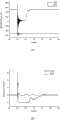
图7(a)为发生直流故障时本发明系统整流侧直流电压波形示意图。Fig. 7(a) is a schematic diagram of the DC voltage waveform on the rectification side of the system of the present invention when a DC fault occurs.
图7(b)为发生直流故障时本发明系统整流侧直流电流波形示意图。Fig. 7(b) is a schematic diagram of the DC current waveform at the rectification side of the system of the present invention when a DC fault occurs.
图7(c)为发生直流故障时本发明系统逆变侧直流电压波形示意图。Fig. 7(c) is a schematic diagram of the DC voltage waveform on the inverter side of the system of the present invention when a DC fault occurs.
图7(d)为发生直流故障时本发明系统逆变侧直流电流波形示意图。Fig. 7(d) is a schematic diagram of the DC current waveform at the inverter side of the system of the present invention when a DC fault occurs.
具体实施方式Detailed ways
为了更为具体地描述本发明,下面结合附图及具体实施方式对本发明的技术方案及其相关原理进行详细说明。In order to describe the present invention more specifically, the technical solutions and related principles of the present invention will be described in detail below in conjunction with the accompanying drawings and specific embodiments.
如图1所示,一种混合双极直流输电系统,包括:整流换流站和逆变换流站,两者通过直流输电线路相连;其中:As shown in Figure 1, a hybrid bipolar DC power transmission system includes: a rectifier converter station and an inverter converter station, both of which are connected through a DC transmission line; where:
整流换流站用于将送端交流电网的三相交流电转换为直流电后通过直流输电线路传送给逆变换流站;The rectification converter station is used to convert the three-phase AC power of the sending end AC grid into DC power and transmit it to the inverter converter station through the DC transmission line;
送端交流电网进站的三相母线上连接有无源滤波器,其具体类型、容量、组数和调谐点等根据系统工程条件来确定,一般可采用双调谐滤波器和并联电容器相配合,以滤除整流换流站所产生的特征次谐波电流,必要时可配置C型滤波器以滤除低次谐波。There is a passive filter connected to the three-phase bus of the AC power grid at the sending end. Its specific type, capacity, group number and tuning point are determined according to the system engineering conditions. Generally, a double tuned filter and a shunt capacitor can be used to cooperate. In order to filter out the characteristic sub-harmonic current generated by the rectification converter station, if necessary, a C-type filter can be configured to filter out the low-order harmonics.
整流换流站由两台晶闸管换流器串联组成,其串联节点接地,串联后的正负两端均通过平波电抗器与直流输电线路相连接;The rectification converter station is composed of two thyristor converters connected in series, the series nodes of which are grounded, and the positive and negative ends of the series connection are connected to the DC transmission line through smoothing reactors;
如图2所示,晶闸管换流器采用十二脉动桥式结构;其中,每个桥臂均由若干个晶闸管串联构成;晶闸管换流器采用定直流电压控制策略控制。As shown in Figure 2, the thyristor converter adopts a twelve-pulse bridge structure; each bridge arm is composed of several thyristors in series; the thyristor converter is controlled by a constant DC voltage control strategy.
晶闸管换流器通过两台接线方式分别为Y0/Δ和Y0/Y的双绕组变压器与送端交流电网连接。变压器能够对送端交流系统的三相交流电进行电压等级交换,以适应所需的直流电压等级,两变压器接线方式的不同为十二脉动桥式晶闸管换流器的上下两个六脉动换流桥提供相角差为30°的三相交流电。The thyristor converter is connected to the AC power grid at the sending end through two double-winding transformers whose wiring modes are Y0 /Δ and Y0 /Y respectively. The transformer can exchange the voltage level of the three-phase AC power of the sending-end AC system to adapt to the required DC voltage level. The difference in the wiring mode of the two transformers is the upper and lower two six-pulse converter bridges of the twelve-pulse bridge thyristor converter Provide three-phase alternating current with a phase angle difference of 30°.
逆变换流站用于将直流电转换为三相交流电后输送给受端交流电网;逆变换流站由两台MMC串联组成,其串联节点接地,串联后的两端口均连接有单向导通功率器件;单向导通功率器件D1的阴极与逆变换流站的正端相连,阳极通过平波电抗器与正极直流输电线路相连接;单向导通功率器件D2的阳极与逆变换流站的正端相连,阴极通过平波电抗器与负极直流输电线路相连接;本实施方式中,单向导通功率器件由多个二极管串联构成。The inverter converter station is used to convert the DC power into three-phase AC power and then transmit it to the AC power grid at the receiving end; the inverter converter station is composed of two MMCs connected in series, the series nodes are grounded, and the two ports connected in series are connected with unidirectional conduction power devices ; The cathode of the one-way conduction power device D1 is connected to the positive terminal of the inverter converter station, and the anode is connected to the positive DC transmission line through a smoothing reactor; the anode of the one-way conduction power device D2 is connected to the positive terminal of the inverter converter station , the cathode is connected to the negative DC transmission line through a smoothing reactor; in this embodiment, the unidirectional conduction power device is composed of a plurality of diodes connected in series.
如图3所示,MMC采用三相六桥臂结构;其中,每个桥臂均由若干个换流模块串联组成;MMC采用定有功功率和定无功功率控制策略控制,MMC通过一台接线方式为Δ/Y0的双绕组变压器与受端交流电网连接。As shown in Figure 3, the MMC adopts a three-phase six-leg structure; each bridge arm is composed of several converter modules connected in series; the MMC is controlled by a constant active power and constant reactive power control strategy, and the MMC is The double-winding transformer whose mode is Δ/Y0 is connected to the AC power grid at the receiving end.
换流模块采用HBSM,如图4所示,其由两个IGBT管T1~T2和一个电容C构成;其中,IGBT管T1的发射极与IGBT管T2的集电极相连并构成HBSM的一端,IGBT管T1的集电极和电容C的一端相连,IGBT管T2的发射极与电容C的另一端相连并构成HBSM的另一端;IGBT管T1~T2的门极均接收外部设备提供的开关信号。The commutation module adopts HBSM, as shown in Figure 4, which is composed of two IGBT tubes T1~T2 and a capacitor C; wherein, the emitter of IGBT tube T1 is connected to the collector of IGBT tube T2 and constitutes one end of HBSM, and the IGBT The collector of the tube T1 is connected to one end of the capacitor C, and the emitter of the IGBT tube T2 is connected to the other end of the capacitor C to form the other end of the HBSM; the gates of the IGBT tubes T1-T2 all receive switching signals provided by external devices.
HBSM的投切策略采用最近电平调制法和子模块电容电压均衡策略。The HBSM switching strategy adopts the nearest level modulation method and the sub-module capacitor voltage equalization strategy.
本实施方式在稳态情况下的基本工作原理如图5所示,正常工作时正极系统与负极系统的整流侧晶闸管换流器通过控制晶闸管触发角的大小来调整直流侧电压的大小,通过整流换流站将三相交流电转变为直流电;正极系统与负极系统的逆变侧MMC负责将直流电能转化为三相交流电能并注入受端交流系统,其能够实现有功无功解耦控制,灵活控制输入到交流电网的有功功率以及无功功率;在直流输电系统中,直流电流从正极系统晶闸管换流器的正端子①流出,经过正极系统平波电抗器的平抑作用,输出的直流电流变得平滑,通过正极系统直流输电线路的输送,直流电能流经正极系统的具有单向导通能力的功率器件,注入正极系统MMC的正端子②,并从其负端子③流出。从③中流出电流的一部分IG2流入逆变侧的接地极,另一部分流入负极系统MMC的正端子④,再从其负端子⑤流出。此部分电流经过负极系统的具有单向导通能力的功率器件、负极直流输电线路和负极系统的平波电抗器后,流入负极系统的晶闸管换流器的负端子⑥,然后再从负极系统的晶闸管换流器的正端子⑦流出。从⑦中流出电流的一部分IG1流入整流侧接地极,另一部分则流入正极系统的晶闸管换流器负端子⑧。The basic working principle of this embodiment in the steady state is shown in Figure 5. During normal operation, the thyristor converters on the rectification side of the positive system and the negative system adjust the size of the DC side voltage by controlling the firing angle of the thyristors. The converter station converts the three-phase AC power into DC power; the MMC on the inverter side of the positive pole system and the negative pole system is responsible for converting the DC power into three-phase AC power and injecting it into the AC system at the receiving end, which can realize decoupling control of active and reactive power and flexible control The active power and reactive power input to the AC grid; in the DC transmission system, the DC current flows out from the positive terminal ① of the thyristor converter in the positive system, and the output DC current becomes Smooth, through the transmission of the DC transmission line of the positive system, the DC power flows through the power device with unidirectional conduction capability of the positive system, injects into the
当正极系统传输的功率与负极系统传输的功率相同的时候,如图5(a)所示,两端直流系统流入接地极的电流IG1以及IG2都为零;当正极系统传输的功率大于负极系统传输的功率的时候,如图5(b)所示,整流侧流入接地极的电流IG1<0逆变侧流入接地极的电流IG2>0;当正极系统传输的功率小于负极系统传输的功率的时候,如图5(c)所示,整流侧流入接地极的电流IG1>0,逆变侧流入接地极的电流IG2<0。When the power transmitted by the positive system is the same as that transmitted by the negative system, as shown in Figure 5(a), the currents IG1 and IG2 flowing into the ground electrode of the DC system at both ends are zero; When transmitting power, as shown in Figure 5(b), the current IG1 flowing into the ground electrode on the rectifier side < 0, the current IG2 flowing into the ground electrode on the inverter side > 0; when the power transmitted by the positive system is less than the power transmitted by the negative system At this time, as shown in FIG. 5( c ), the current IG1 flowing into the ground electrode at the rectification side is >0, and the current IG2 flowing into the ground electrode at the inverter side is <0.
本实施方式在直流故障时的自清理故障的原理如下:在直流线路发生正极(或负极)直流接地短路故障时,如图6(a)与6(b)所示,正极(或负极)整流侧晶闸管换流器闭锁,则正极(或负极)整流侧输出的直流电流降为零,即不会产生直流故障的过电流。正极(或负极)逆变侧由于具有单向导通能力的大功率器件反向截止的作用,截断了逆变侧交流系统与故障点之间的能量馈路,亦不会产生直流故障的过电流。此时系统由正常运行模式切换到单极运行模式;在直流线路发生双极直流故障时,如图6(c)所示,整流侧晶闸管换流器全部闭锁,则整流侧输出的直流电流下降为零,即不会产生直流故障的过电流。逆变侧由于具有单向导通能力的功率器件反向截止的作用,截断了逆变侧交流系统与故障点之间的能量馈路,亦不会产生直流故障的过电流。此时直流输电系统所连接的两端交流系统不再有能量交换,直流系统进入运行重启动的等待模式。The principle of the self-cleaning fault of this embodiment in the event of a DC fault is as follows: When a positive (or negative) DC ground short circuit fault occurs on the DC line, as shown in Figures 6(a) and 6(b), the positive (or negative) rectifier When the side thyristor converter is blocked, the DC current output from the positive (or negative) rectification side drops to zero, that is, no overcurrent of DC fault will occur. On the positive (or negative) inverter side, due to the reverse cut-off function of the high-power device with unidirectional conduction capability, the energy feed between the AC system on the inverter side and the fault point is cut off, and the overcurrent of the DC fault will not be generated. . At this time, the system switches from normal operation mode to unipolar operation mode; when a bipolar DC fault occurs on the DC line, as shown in Figure 6(c), all thyristor converters on the rectification side are blocked, and the output DC current on the rectification side drops is zero, that is, there will be no overcurrent for DC faults. On the inverter side, due to the reverse cut-off function of the power device with unidirectional conduction capability, the energy feed between the AC system on the inverter side and the fault point is cut off, and the overcurrent of the DC fault will not be generated. At this time, the AC systems at both ends connected to the DC transmission system no longer have energy exchange, and the DC system enters the waiting mode for operation restart.
为了进一步验证本实施方式的有效性和可行性,通过在电力系统暂态仿真软件PSCAD/EMTDC中搭建相应模型,具体仿真参数如表1所示。In order to further verify the effectiveness and feasibility of this embodiment, the corresponding model is built in the power system transient simulation software PSCAD/EMTDC, and the specific simulation parameters are shown in Table 1.
表1Table 1

单极接地故障是输电线路最容易发生的故障类型,传统直流输电系统能够通过强迫移相使整流器进入逆变方式,令弧道电流和弧道电压迅速降低到零以实现故障快速消除。鉴于直流断路器研制困难和自身拓扑特点等原因,发生直流故障后直接跳开交流侧的断路器是基于MMC输电系统常用的手段。而本实施方式在逆变侧换流器直流出口处加装了具有单向导通能力的功率器件,阻断了逆变侧交流系统与直流故障点之间的能量馈路,快速地实现了直流故障的清理。假设故障发生在正极直流输电线路中间距离逆变侧500km处,故障于6s引入。整流侧换流站在故障发生后5ms即发出闭锁信号,短路故障消失后,故障的输电线路去能,再经过一段无电压时间(大约为0.2~0.5s),本例选取0.4s,让闪络故障经过充分去游离,输电线路的绝缘性能恢复到能够承受正常电压。2s时系统重启动,整流器解锁,其直流电压指令值udlord以10.5pu/s的速率增长至1.05pu;同时解锁逆变侧MMC,逆变侧交流系统吸收的有功功率及无功功率指令值Pord、Qord以1pu/s的速率分别由0增长至1pu和0.3pu;在故障重启动后系统恢复稳态运行;故障响应特性如图7所示。其中图7(a)为发生直流故障时整流侧直流电压随时间变化的波形;图7(b)为发生直流故障时整流侧直流电流随时间变化的波形;由图可见,在发生正极直流故障后,整流侧正极传统直流输电换流站通过强迫换向使之闭锁,而整流侧负极传统直流输电换流站直流电压电流在小幅波动后运行状态正常。图7(c)为发生直流故障时逆变侧直流电压随时间变化的波形;图7(d)为发生直流故障时逆变侧直流电流随时间变化的波形;由图可见,在发生正极直流故障后,逆变侧正极换流站由于直流出口处单向导通能力的大功率器件的反向截止作用,直流电流降为0,而逆变侧负极换流站直流电压电流在小幅波动后运行状态正常。在故障清除之后,系统能够平滑地恢复至稳定运行值。从上述仿真结果可得,在逆变站直流出口加装具有单向导通能力的功率器件能够有效地清理直流故障,解决了模块化多电平换流器无法处理直流故障的问题。Unipolar ground fault is the most common type of fault on the transmission line. The traditional DC transmission system can make the rectifier enter the inverter mode through forced phase shift, so that the arc current and arc voltage can be quickly reduced to zero to realize the rapid elimination of the fault. In view of the difficulties in the development of DC circuit breakers and their own topology characteristics, it is a common method based on MMC power transmission systems to directly trip the circuit breaker on the AC side after a DC fault occurs. In this embodiment, a power device with unidirectional conduction capability is installed at the DC outlet of the converter on the inverter side, which blocks the energy feed between the AC system on the inverter side and the DC fault point, and quickly realizes DC Troubleshooting. Assume that the fault occurs at a distance of 500km from the inverter side in the middle of the positive DC transmission line, and the fault is introduced in 6s. The converter station on the rectification side sends out a blocking signal 5ms after the fault occurs. After the short-circuit fault disappears, the faulty transmission line is de-energized, and after a period of no-voltage time (about 0.2-0.5s), this example selects 0.4s to allow the flash After the network fault is fully de-ionized, the insulation performance of the transmission line is restored to be able to withstand the normal voltage. At 2s, the system restarts, the rectifier is unlocked, and its DC voltage command value udlord increases to 1.05pu at a rate of 10.5pu/s; at the same time, the inverter side MMC is unlocked, and the active power and reactive power command value absorbed by the inverter side AC system Pord and Qord increase from 0 to 1pu and 0.3pu respectively at a rate of 1pu/s; the system returns to steady-state operation after the fault restarts; the fault response characteristics are shown in Figure 7. Figure 7(a) is the waveform of the DC voltage on the rectifier side changing with time when a DC fault occurs; Figure 7(b) is the waveform of the DC current on the rectifying side changing with time when a DC fault occurs; it can be seen from the figure that when a positive DC fault occurs Afterwards, the traditional HVDC converter station at the positive pole on the rectification side locks it through forced commutation, while the DC voltage and current of the traditional HVDC converter station at the negative pole on the rectification side run normally after small fluctuations. Figure 7(c) is the waveform of the DC voltage of the inverter side changing with time when a DC fault occurs; Figure 7(d) is the waveform of the DC current of the inverter side changing with time when a DC fault occurs; it can be seen from the figure that in the event of a positive DC After the fault, due to the reverse cut-off effect of the high-power device with unidirectional conduction capacity at the DC outlet, the DC current of the positive converter station on the inverter side drops to 0, while the DC voltage and current of the negative converter station on the inverter side run after a small fluctuation The status is normal. After the fault is cleared, the system can smoothly return to the stable operating value. From the above simulation results, it can be concluded that installing a power device with unidirectional conduction capability at the DC outlet of the inverter station can effectively clean up DC faults and solve the problem that the modular multilevel converter cannot handle DC faults.
因此,本实施方式的混合型直流输电系统,兼具传统晶闸管换流器造价低、损耗低、可靠性强等优点,以及MMC控制灵活、低谐波、有功无功功率解耦控制、对交流系统依赖性低等优点。系统分为正负两极加强了系统运行的可靠性,并且在逆变器出口处加装的具有单向导通能力的功率器件能够有效地处理直流故障。因此,本发明适用于大功率、长距离高压直流输电、孤岛送电等场合,具有广阔的发展空间,值得大力推广。Therefore, the hybrid DC transmission system of this embodiment has the advantages of low cost, low loss, and strong reliability of traditional thyristor converters, as well as flexible MMC control, low harmonics, active and reactive power decoupling control, and AC The advantages of low system dependence. The system is divided into positive and negative poles to enhance the reliability of the system operation, and the power device with unidirectional conduction capability installed at the outlet of the inverter can effectively deal with DC faults. Therefore, the present invention is applicable to occasions such as high-power, long-distance high-voltage direct current transmission, isolated island power transmission, etc., has broad development space, and is worthy of vigorous promotion.
Claims (8)
Translated fromChinesePriority Applications (1)
| Application Number | Priority Date | Filing Date | Title |
|---|---|---|---|
| CN201210431652.1ACN102969732B (en) | 2012-11-01 | 2012-11-01 | Mixed bipolar direct current (DC) transmission system |
Applications Claiming Priority (1)
| Application Number | Priority Date | Filing Date | Title |
|---|---|---|---|
| CN201210431652.1ACN102969732B (en) | 2012-11-01 | 2012-11-01 | Mixed bipolar direct current (DC) transmission system |
Publications (2)
| Publication Number | Publication Date |
|---|---|
| CN102969732Atrue CN102969732A (en) | 2013-03-13 |
| CN102969732B CN102969732B (en) | 2015-06-17 |
Family
ID=47799692
Family Applications (1)
| Application Number | Title | Priority Date | Filing Date |
|---|---|---|---|
| CN201210431652.1AExpired - Fee RelatedCN102969732B (en) | 2012-11-01 | 2012-11-01 | Mixed bipolar direct current (DC) transmission system |
Country Status (1)
| Country | Link |
|---|---|
| CN (1) | CN102969732B (en) |
Cited By (36)
| Publication number | Priority date | Publication date | Assignee | Title |
|---|---|---|---|---|
| CN103219738A (en)* | 2013-03-29 | 2013-07-24 | 浙江大学 | Direct current transmission system based on three-pole type structure |
| CN103326622A (en)* | 2013-06-19 | 2013-09-25 | 国家电网公司 | Photovoltaic system suitable for high-voltage direct-current transmission |
| CN103427433A (en)* | 2013-08-12 | 2013-12-04 | 浙江大学 | Calculation method for direct-current loop impedance of hybrid bipolar direct-current transmission system |
| CN103701145A (en)* | 2014-01-02 | 2014-04-02 | 浙江大学 | Mixed MMC-based mixed direct current power transmission system |
| CN104167752A (en)* | 2013-05-16 | 2014-11-26 | 南京南瑞继保电气有限公司 | Three-pole direct current power transmission control system configuration method |
| CN104242341A (en)* | 2014-09-12 | 2014-12-24 | 周细文 | Direct-drive wind power conversion structure based on MMC and bipolar direct-current transmission structure |
| CN104300527A (en)* | 2014-10-09 | 2015-01-21 | 南方电网科学研究院有限责任公司 | Control processing method for extra-high voltage direct current project operation in grounding electrode-free mode |
| CN104505866A (en)* | 2014-12-31 | 2015-04-08 | 华南理工大学 | Equivalent decoupling method for simulating multi-feed-in direct current fault recovery characteristics |
| US9099936B2 (en) | 2013-03-14 | 2015-08-04 | General Electric Company | High voltage direct current (HVDC) converter system and method of operating the same |
| CN105162155A (en)* | 2015-08-26 | 2015-12-16 | 浙江大学 | Series hybrid bipolar direct-current transmission system with direct-current fault ride-through capability |
| CN105449704A (en)* | 2015-12-10 | 2016-03-30 | 特变电工新疆新能源股份有限公司 | Flexible direct-current power transmission system and direct-current fault processing method thereof |
| CN105978014A (en)* | 2016-06-08 | 2016-09-28 | 南京南瑞继保电气有限公司 | Fault locking method under communication abnormity between parallel connection converter DC power stations |
| US9515565B2 (en) | 2014-03-07 | 2016-12-06 | General Electric Company | Hybrid high voltage direct current converter systems |
| US9537421B2 (en) | 2014-08-22 | 2017-01-03 | General Electric Company | Multilevel converter |
| CN106356881A (en)* | 2016-10-21 | 2017-01-25 | 南京南瑞继保电气有限公司 | Flexible direct current power transmission system and fault recovery method thereof |
| US9602021B2 (en) | 2014-03-07 | 2017-03-21 | General Electric Company | Hybrid high voltage direct current converter system and method of operating the same |
| CN106786723A (en)* | 2017-01-18 | 2017-05-31 | 浙江大学 | A kind of hybrid direct current transportation topological structure with DC Line Fault self-cleaning ability |
| CN106877298A (en)* | 2017-03-27 | 2017-06-20 | 上海交通大学 | MMC‑HVDC system DC transmission line protection method |
| CN107171579A (en)* | 2017-06-30 | 2017-09-15 | 天津滨海光热技术研究院有限公司 | Joule heating device and the light field with electric heating function |
| CN107204626A (en)* | 2017-06-09 | 2017-09-26 | 电子科技大学 | A kind of LCC MMC interlock hybrid bypolar DC transmission system |
| CN107534296A (en)* | 2015-04-28 | 2018-01-02 | 通用电器技术有限公司 | Bipolar DC electric power transmission structure |
| CN107565590A (en)* | 2017-09-06 | 2018-01-09 | 合肥工业大学 | The mixed high-voltage DC transmission system sent outside suitable for wind-powered electricity generation |
| CN108155659A (en)* | 2018-01-05 | 2018-06-12 | 南方电网科学研究院有限责任公司 | Direct current passive island anti-error processing system based on alternating current tie line power |
| CN108376993A (en)* | 2018-04-24 | 2018-08-07 | 国网冀北电力有限公司检修分公司 | It is a kind of be suitable for flexible direct current islet operation when exchange energy-consuming device |
| CN108390575A (en)* | 2018-03-27 | 2018-08-10 | 江苏科技大学 | A kind of current converter for shipping shore power system |
| CN108736506A (en)* | 2018-08-02 | 2018-11-02 | 南方电网科学研究院有限责任公司 | High-voltage direct-current transmission system |
| CN108964111A (en)* | 2018-08-22 | 2018-12-07 | 国家电网有限公司 | Direct-current power transmission system with medium-voltage side direct-current outgoing line and control method thereof |
| CN109066760A (en)* | 2018-08-29 | 2018-12-21 | 东南大学 | A kind of high pressure side goes out the Hybrid HVDC and current-sharing control method of DC line |
| WO2019012250A1 (en)* | 2017-07-13 | 2019-01-17 | The University Of Birmingham | Elimination of commutation failure of lcc hvdc system |
| CN110912175A (en)* | 2019-12-03 | 2020-03-24 | 国网河南省电力公司电力科学研究院 | Hybrid four-terminal high-voltage direct-current transmission system |
| CN111355254A (en)* | 2019-12-09 | 2020-06-30 | 国网江苏省电力有限公司 | Method and system for determining configuration quantity of filter in direct current converter station |
| US10861657B2 (en) | 2015-08-05 | 2020-12-08 | Abb Power Grids Switzerland Ag | Bidirectional power valve and control method therefor and hybrid multi-terminal HVDC system using the same |
| EP2830200B1 (en)* | 2013-07-25 | 2022-05-11 | General Electric Technology GmbH | A power converter |
| CN115102216A (en)* | 2022-07-27 | 2022-09-23 | 上海交通大学 | Alternating current-direct current hybrid power supply circuit |
| CN115207980A (en)* | 2022-08-30 | 2022-10-18 | 南方电网科学研究院有限责任公司 | Direct-current fault self-clearing method of new energy island power grid sending-out system |
| CN119813792A (en)* | 2024-12-09 | 2025-04-11 | 国家电网有限公司华东分部 | High-voltage direct-current transformer with symmetrical bipolar structure |
Citations (3)
| Publication number | Priority date | Publication date | Assignee | Title |
|---|---|---|---|---|
| EP0554804A1 (en)* | 1992-01-30 | 1993-08-11 | Hitachi, Ltd. | Control equipment for high voltage direct current transmission system |
| CN102231520A (en)* | 2011-06-20 | 2011-11-02 | 浙江大学 | Hybrid DC (direct current) electric power transmission system |
| CN102361329A (en)* | 2011-10-18 | 2012-02-22 | 山东电力研究院 | Modeling method for performing dynamic characteristic research on hybrid alternating current/direct current (AC/DC) transmission system |
- 2012
- 2012-11-01CNCN201210431652.1Apatent/CN102969732B/ennot_activeExpired - Fee Related
Patent Citations (4)
| Publication number | Priority date | Publication date | Assignee | Title |
|---|---|---|---|---|
| EP0554804A1 (en)* | 1992-01-30 | 1993-08-11 | Hitachi, Ltd. | Control equipment for high voltage direct current transmission system |
| EP0554804B1 (en)* | 1992-01-30 | 1999-12-22 | Hitachi, Ltd. | Control equipment for high voltage direct current transmission system |
| CN102231520A (en)* | 2011-06-20 | 2011-11-02 | 浙江大学 | Hybrid DC (direct current) electric power transmission system |
| CN102361329A (en)* | 2011-10-18 | 2012-02-22 | 山东电力研究院 | Modeling method for performing dynamic characteristic research on hybrid alternating current/direct current (AC/DC) transmission system |
Non-Patent Citations (2)
| Title |
|---|
| 丁一: "高压直流输电系统控制的研究", 《中国优秀硕士学位论文全文数据库》, 30 September 2003 (2003-09-30), pages 1 - 22* |
| 管敏渊等: "模块化多电平换流器子模块故障特性和冗余保护", 《电力系统自动化》, vol. 35, no. 16, 25 August 2011 (2011-08-25)* |
Cited By (55)
| Publication number | Priority date | Publication date | Assignee | Title |
|---|---|---|---|---|
| US9099936B2 (en) | 2013-03-14 | 2015-08-04 | General Electric Company | High voltage direct current (HVDC) converter system and method of operating the same |
| CN103219738B (en)* | 2013-03-29 | 2015-05-20 | 浙江大学 | Direct current transmission system based on three-pole type structure |
| CN103219738A (en)* | 2013-03-29 | 2013-07-24 | 浙江大学 | Direct current transmission system based on three-pole type structure |
| CN104167752A (en)* | 2013-05-16 | 2014-11-26 | 南京南瑞继保电气有限公司 | Three-pole direct current power transmission control system configuration method |
| CN104167752B (en)* | 2013-05-16 | 2016-12-28 | 南京南瑞继保电气有限公司 | A kind of three pole DC power transmission control system configuring methods |
| CN103326622A (en)* | 2013-06-19 | 2013-09-25 | 国家电网公司 | Photovoltaic system suitable for high-voltage direct-current transmission |
| EP2830200B1 (en)* | 2013-07-25 | 2022-05-11 | General Electric Technology GmbH | A power converter |
| CN103427433B (en)* | 2013-08-12 | 2015-06-24 | 浙江大学 | Calculation method for direct-current loop impedance of hybrid bipolar direct-current transmission system |
| CN103427433A (en)* | 2013-08-12 | 2013-12-04 | 浙江大学 | Calculation method for direct-current loop impedance of hybrid bipolar direct-current transmission system |
| CN103701145A (en)* | 2014-01-02 | 2014-04-02 | 浙江大学 | Mixed MMC-based mixed direct current power transmission system |
| US9602021B2 (en) | 2014-03-07 | 2017-03-21 | General Electric Company | Hybrid high voltage direct current converter system and method of operating the same |
| US9515565B2 (en) | 2014-03-07 | 2016-12-06 | General Electric Company | Hybrid high voltage direct current converter systems |
| US9537421B2 (en) | 2014-08-22 | 2017-01-03 | General Electric Company | Multilevel converter |
| CN104242341A (en)* | 2014-09-12 | 2014-12-24 | 周细文 | Direct-drive wind power conversion structure based on MMC and bipolar direct-current transmission structure |
| CN104300527B (en)* | 2014-10-09 | 2016-08-17 | 南方电网科学研究院有限责任公司 | Control processing method for extra-high voltage direct current project operation in grounding electrode-free mode |
| CN104300527A (en)* | 2014-10-09 | 2015-01-21 | 南方电网科学研究院有限责任公司 | Control processing method for extra-high voltage direct current project operation in grounding electrode-free mode |
| CN104505866A (en)* | 2014-12-31 | 2015-04-08 | 华南理工大学 | Equivalent decoupling method for simulating multi-feed-in direct current fault recovery characteristics |
| CN107534296B (en)* | 2015-04-28 | 2020-10-16 | 通用电器技术有限公司 | Bipolar DC power transmission structure |
| CN107534296A (en)* | 2015-04-28 | 2018-01-02 | 通用电器技术有限公司 | Bipolar DC electric power transmission structure |
| US10861657B2 (en) | 2015-08-05 | 2020-12-08 | Abb Power Grids Switzerland Ag | Bidirectional power valve and control method therefor and hybrid multi-terminal HVDC system using the same |
| CN105162155A (en)* | 2015-08-26 | 2015-12-16 | 浙江大学 | Series hybrid bipolar direct-current transmission system with direct-current fault ride-through capability |
| CN105162155B (en)* | 2015-08-26 | 2017-10-27 | 浙江大学 | A kind of series hybrid bipolar direct current transmission system with DC Line Fault ride-through capability |
| CN105449704B (en)* | 2015-12-10 | 2018-11-02 | 特变电工新疆新能源股份有限公司 | Flexible direct-current power transmission system and direct-current fault processing method thereof |
| CN105449704A (en)* | 2015-12-10 | 2016-03-30 | 特变电工新疆新能源股份有限公司 | Flexible direct-current power transmission system and direct-current fault processing method thereof |
| CN105978014A (en)* | 2016-06-08 | 2016-09-28 | 南京南瑞继保电气有限公司 | Fault locking method under communication abnormity between parallel connection converter DC power stations |
| CN105978014B (en)* | 2016-06-08 | 2018-09-28 | 南京南瑞继保电气有限公司 | Parallel inverter direct current transportation interior communication descends failure locking method extremely |
| CN106356881A (en)* | 2016-10-21 | 2017-01-25 | 南京南瑞继保电气有限公司 | Flexible direct current power transmission system and fault recovery method thereof |
| CN106356881B (en)* | 2016-10-21 | 2018-08-17 | 南京南瑞继保电气有限公司 | A kind of flexible direct current power transmission system and its fault recovery method |
| CN106786723A (en)* | 2017-01-18 | 2017-05-31 | 浙江大学 | A kind of hybrid direct current transportation topological structure with DC Line Fault self-cleaning ability |
| CN106877298B (en)* | 2017-03-27 | 2018-09-21 | 上海交通大学 | MMC-HVDC system dc line protection methods |
| CN106877298A (en)* | 2017-03-27 | 2017-06-20 | 上海交通大学 | MMC‑HVDC system DC transmission line protection method |
| CN107204626B (en)* | 2017-06-09 | 2021-05-11 | 电子科技大学 | A LCC-MMC Interleaved Hybrid Bipolar DC Transmission System |
| CN107204626A (en)* | 2017-06-09 | 2017-09-26 | 电子科技大学 | A kind of LCC MMC interlock hybrid bypolar DC transmission system |
| CN107171579A (en)* | 2017-06-30 | 2017-09-15 | 天津滨海光热技术研究院有限公司 | Joule heating device and the light field with electric heating function |
| US11165330B2 (en) | 2017-07-13 | 2021-11-02 | The University Of Birmingham | Elimination of commutation failure of LCC HVDC system |
| WO2019012250A1 (en)* | 2017-07-13 | 2019-01-17 | The University Of Birmingham | Elimination of commutation failure of lcc hvdc system |
| CN107565590A (en)* | 2017-09-06 | 2018-01-09 | 合肥工业大学 | The mixed high-voltage DC transmission system sent outside suitable for wind-powered electricity generation |
| CN107565590B (en)* | 2017-09-06 | 2020-05-05 | 合肥工业大学 | Hybrid high-voltage direct-current power transmission system suitable for wind power transmission |
| CN108155659A (en)* | 2018-01-05 | 2018-06-12 | 南方电网科学研究院有限责任公司 | Direct current passive island anti-error processing system based on alternating current tie line power |
| CN108390575B (en)* | 2018-03-27 | 2023-11-14 | 江苏科技大学 | A converter device for ship shore power system |
| CN108390575A (en)* | 2018-03-27 | 2018-08-10 | 江苏科技大学 | A kind of current converter for shipping shore power system |
| CN108376993A (en)* | 2018-04-24 | 2018-08-07 | 国网冀北电力有限公司检修分公司 | It is a kind of be suitable for flexible direct current islet operation when exchange energy-consuming device |
| CN108736506A (en)* | 2018-08-02 | 2018-11-02 | 南方电网科学研究院有限责任公司 | High-voltage direct-current transmission system |
| CN108736506B (en)* | 2018-08-02 | 2023-12-01 | 南方电网科学研究院有限责任公司 | A high voltage direct current transmission system |
| CN108964111B (en)* | 2018-08-22 | 2020-06-30 | 国家电网有限公司 | Direct-current power transmission system with medium-voltage side direct-current outgoing line and control method thereof |
| CN108964111A (en)* | 2018-08-22 | 2018-12-07 | 国家电网有限公司 | Direct-current power transmission system with medium-voltage side direct-current outgoing line and control method thereof |
| CN109066760A (en)* | 2018-08-29 | 2018-12-21 | 东南大学 | A kind of high pressure side goes out the Hybrid HVDC and current-sharing control method of DC line |
| CN110912175A (en)* | 2019-12-03 | 2020-03-24 | 国网河南省电力公司电力科学研究院 | Hybrid four-terminal high-voltage direct-current transmission system |
| CN111355254A (en)* | 2019-12-09 | 2020-06-30 | 国网江苏省电力有限公司 | Method and system for determining configuration quantity of filter in direct current converter station |
| CN111355254B (en)* | 2019-12-09 | 2022-09-23 | 国网江苏省电力有限公司 | Method and system for determining configuration quantity of filter in direct current converter station |
| CN115102216A (en)* | 2022-07-27 | 2022-09-23 | 上海交通大学 | Alternating current-direct current hybrid power supply circuit |
| CN115102216B (en)* | 2022-07-27 | 2024-05-14 | 上海交通大学 | AC/DC hybrid power supply circuit |
| CN115207980A (en)* | 2022-08-30 | 2022-10-18 | 南方电网科学研究院有限责任公司 | Direct-current fault self-clearing method of new energy island power grid sending-out system |
| CN115207980B (en)* | 2022-08-30 | 2025-08-01 | 南方电网科学研究院有限责任公司 | Direct-current fault self-cleaning method for new energy island power grid delivery system |
| CN119813792A (en)* | 2024-12-09 | 2025-04-11 | 国家电网有限公司华东分部 | High-voltage direct-current transformer with symmetrical bipolar structure |
Also Published As
| Publication number | Publication date |
|---|---|
| CN102969732B (en) | 2015-06-17 |
Similar Documents
| Publication | Publication Date | Title |
|---|---|---|
| CN102969732B (en) | Mixed bipolar direct current (DC) transmission system | |
| CN105162155B (en) | A kind of series hybrid bipolar direct current transmission system with DC Line Fault ride-through capability | |
| CN103219738B (en) | Direct current transmission system based on three-pole type structure | |
| CN103997033B (en) | A kind of HVDC transmission system possessing DC Line Fault ride-through capability | |
| CN104753043B (en) | Multi-level current converter with direct-current fault ride-through capability and working method | |
| CN107565590A (en) | The mixed high-voltage DC transmission system sent outside suitable for wind-powered electricity generation | |
| CN107994613A (en) | A kind of the alternating current-direct current fault traversing and energy dissipation method of the soft direct join net of wind-powered electricity generation | |
| CN107204626A (en) | A kind of LCC MMC interlock hybrid bypolar DC transmission system | |
| CN103701145A (en) | Mixed MMC-based mixed direct current power transmission system | |
| CN102938560A (en) | Direct-current converter station based on bipolar structure | |
| CN106786723A (en) | A kind of hybrid direct current transportation topological structure with DC Line Fault self-cleaning ability | |
| CN107994597A (en) | High-voltage large-capacity overhead line flexible direct current power transmission system fault ride-through method | |
| WO2023134225A1 (en) | Low-frequency power transmission system and control mode therefor | |
| CN108448542A (en) | Sub-module structure and MMC topology with AC and DC fault clearing capabilities | |
| CN116131325A (en) | A solid-state transformer for direct current collection and transmission in long-distance offshore wind farms | |
| CN111884246B (en) | Direct-current fault clearing method of layered series-parallel direct-current transmission system | |
| Wu et al. | A hybrid HVDC converter based on MMC and diode rectifier for offshore wind farm integration | |
| CN111600328A (en) | Power balancing device and control method for new energy flexible direct-sending system | |
| CN106972541A (en) | A kind of power distribution network multiterminal flexible interconnection switch based on mixed type submodule MMC | |
| CN115189341B (en) | Full direct current power system | |
| CN103545839A (en) | Low voltage control device for wind power generating set | |
| CN111276995A (en) | Power balance device and control method for offshore wind power flexible direct transmission system | |
| Liu et al. | Current status and key issues of HVDC transmission research: A brief review | |
| CN203617721U (en) | Low voltage adjusting and controlling device for wind turbine | |
| CN210744758U (en) | A Multi-terminal HVDC Transmission System Based on Superconducting Current Limiter |
Legal Events
| Date | Code | Title | Description |
|---|---|---|---|
| C06 | Publication | ||
| PB01 | Publication | ||
| C10 | Entry into substantive examination | ||
| SE01 | Entry into force of request for substantive examination | ||
| C14 | Grant of patent or utility model | ||
| GR01 | Patent grant | ||
| CF01 | Termination of patent right due to non-payment of annual fee | ||
| CF01 | Termination of patent right due to non-payment of annual fee | Granted publication date:20150617 Termination date:20181101 |