CN102967297A - Space-movable visual sensor array system and image information fusion method - Google Patents
Space-movable visual sensor array system and image information fusion methodDownload PDFInfo
- Publication number
- CN102967297A CN102967297ACN2012104835006ACN201210483500ACN102967297ACN 102967297 ACN102967297 ACN 102967297ACN 2012104835006 ACN2012104835006 ACN 2012104835006ACN 201210483500 ACN201210483500 ACN 201210483500ACN 102967297 ACN102967297 ACN 102967297A
- Authority
- CN
- China
- Prior art keywords
- visual sensor
- level ground
- image
- ground station
- node
- Prior art date
- Legal status (The legal status is an assumption and is not a legal conclusion. Google has not performed a legal analysis and makes no representation as to the accuracy of the status listed.)
- Granted
Links
- 230000000007visual effectEffects0.000titleclaimsabstractdescription108
- 238000007500overflow downdraw methodMethods0.000titleclaimsabstractdescription14
- RZVHIXYEVGDQDX-UHFFFAOYSA-N9,10-anthraquinoneChemical compoundC1=CC=C2C(=O)C3=CC=CC=C3C(=O)C2=C1RZVHIXYEVGDQDX-UHFFFAOYSA-N0.000claimsabstractdescription34
- 230000004927fusionEffects0.000claimsabstractdescription32
- 230000005540biological transmissionEffects0.000claimsabstractdescription19
- 238000000034methodMethods0.000claimsdescription18
- 238000007792additionMethods0.000claimsdescription10
- 230000015572biosynthetic processEffects0.000claimsdescription9
- 230000009466transformationEffects0.000claimsdescription6
- 238000004891communicationMethods0.000claimsdescription5
- 238000000605extractionMethods0.000claimsdescription5
- 230000002159abnormal effectEffects0.000claimsdescription4
- 230000005856abnormalityEffects0.000claimsdescription4
- 230000000694effectsEffects0.000abstractdescription3
- 238000010586diagramMethods0.000description8
- 238000004364calculation methodMethods0.000description5
- 230000006870functionEffects0.000description5
- 238000007499fusion processingMethods0.000description3
- 238000013507mappingMethods0.000description3
- 238000010276constructionMethods0.000description2
- 238000001514detection methodMethods0.000description2
- 238000012545processingMethods0.000description2
- 230000001960triggered effectEffects0.000description2
- 230000009286beneficial effectEffects0.000description1
- 230000007812deficiencyEffects0.000description1
- 238000013461designMethods0.000description1
- 238000005516engineering processMethods0.000description1
- 238000012544monitoring processMethods0.000description1
- 238000011160researchMethods0.000description1
- 230000004044responseEffects0.000description1
- 230000001629suppressionEffects0.000description1
- 230000001360synchronised effectEffects0.000description1
Images


Landscapes
- Image Processing (AREA)
- Traffic Control Systems (AREA)
Abstract
Translated fromChinese
Description
Translated fromChinese技术领域technical field
本发明涉及一种视觉传感器阵列系统及方法,特别地,涉及一种基于多微小型旋翼无人机的空间可移动视觉传感器阵列系统及图像信息融合方法。The present invention relates to a visual sensor array system and method, in particular to a spatially movable visual sensor array system and image information fusion method based on multi-miniature rotor drones.
背景技术Background technique
当今基于微小型旋翼无人机视觉系统的需求已经不再只是局限于单一视角的图像采集与处理,对于微小型旋翼无人机航拍的效果和效率都提出了更高的要求。针对这种情况,需要设计基于多微小型无人机的新型视觉系统。Today's micro-rotor UAV-based vision system requirements are no longer limited to single-view image acquisition and processing, and have put forward higher requirements for the effect and efficiency of micro-rotor UAV aerial photography. In response to this situation, it is necessary to design a new vision system based on multi-miniature drones.
微小型旋翼无人机具有自主飞行、自主降落、自主规划航迹的能力。Micro-rotor drones have the ability to fly autonomously, land autonomously, and plan flight paths autonomously.
传统微小型旋翼无人机视觉系统特点如下:The characteristics of the vision system of the traditional miniature rotor UAV are as follows:
1、一架微小型旋翼无人机执行图像采集任务,微小型旋翼无人机搭载1个摄像头;1. A micro-rotor UAV performs image acquisition tasks, and the micro-rotor UAV is equipped with a camera;
2、采集视场较大的区域获取完整图像的方法是增加微小型旋翼无人机飞行高度,牺牲图像分辨率;2. The method of acquiring a complete image in a larger field of view is to increase the flying height of the micro-rotor UAV and sacrifice the image resolution;
3、地图测绘的方法是1架微小型旋翼无人机搭载1个摄像头,采用图像逐行扫描的方式获得指定区域地图信息,对微小型旋翼无人机飞行时间与航向精度都有很高的要求。3. The method of map surveying and mapping is that a micro-rotor UAV is equipped with a camera, and the map information of the designated area is obtained by scanning the image line by line, which has a high accuracy for the flight time and heading accuracy of the micro-rotor UAV. Require.
基于1架微小型旋翼无人机搭载1个摄像头的视觉系统,不具有在保证图像分辨率的前提下获取较大视场图像的能力,不能并行地对目标区域进行视频采集实现地图测绘。A vision system based on a micro-rotor UAV equipped with a camera does not have the ability to obtain images of a larger field of view under the premise of ensuring image resolution, and cannot perform video acquisition of the target area in parallel to realize map mapping.
从目前的技术来看,基于无人机的视觉系统的研究更多的处于实验阶段,真正实际应用的较少。Judging from the current technology, the research on the vision system based on UAV is more in the experimental stage, and the real practical application is less.
发明内容Contents of the invention
本发明的目的在于针对现有技术的不足,提供一种空间可移动视觉传感器阵列系统及图像信息融合方法。The object of the present invention is to provide a spatially movable visual sensor array system and an image information fusion method for the deficiencies of the prior art.
本发明的目的是通过以下技术方案来实现的:一种空间可移动视觉传感器阵列系统,它由多个视觉传感器节点、若干个第一级地面站和一个第二级地面站组成;三个视觉传感器节点组成一个组,与一个第一级地面站间通信采用无线方式通信,所有第一级地面站与第二级地面站采用有线以太网通信;其中,所述视觉传感器节点主要包括飞行控制模块、飞行管理模块、摄像头、数字传输电台、无线网卡和微小型旋翼无人机机体;所述飞行控制模块、飞行管理模块、摄像头、数字传输电台和无线网卡均固定在微小型旋翼无人机机体上,飞行控制模块、摄像头、数字传输电台和无线网卡均与飞行管理模块相连;视觉传感器节点通过数字传输电台发送飞行状态信息给第一级地面站,从第一级地面站接收指令;通过无线网卡发送图像数据到第一级地面站;所述第一级地面站和第二级地面站均为计算机。The purpose of the present invention is achieved through the following technical solutions: a spatially movable visual sensor array system, which is composed of multiple visual sensor nodes, several first-level ground stations and a second-level ground station; three visual The sensor nodes form a group, and communicate with a first-level ground station using wireless communication, and all first-level ground stations communicate with the second-level ground station using wired Ethernet; wherein, the visual sensor nodes mainly include flight control modules , a flight management module, a camera, a digital transmission radio station, a wireless network card and a micro rotor UAV body; the flight control module, a flight management module, a camera, a digital transmission radio station and a wireless network card are all fixed on the micro rotor UAV Above, the flight control module, camera, digital transmission radio station and wireless network card are all connected to the flight management module; the visual sensor node sends flight status information to the first-level ground station through the digital transmission station, and receives instructions from the first-level ground station; The network card sends the image data to the first-level ground station; both the first-level ground station and the second-level ground station are computers.
进一步地,所述飞行控制模块包括DSP、FPGA、惯性器件、GPS接收器、高度传感器和空速传感器;其中,所述GPS接收器、高度传感器和空速传感器均与FPGA相连,FPGA与DSP相连,惯性器件与DSP相连。Further, the flight control module includes DSP, FPGA, inertial device, GPS receiver, altitude sensor and airspeed sensor; wherein, the GPS receiver, altitude sensor and airspeed sensor are all connected to FPGA, and FPGA is connected to DSP , The inertial device is connected with DSP.
一种在上述系统上实现的实时图像信息融合方法,主要包括以下步骤:A real-time image information fusion method realized on the above-mentioned system mainly includes the following steps:
(1)视觉传感器阵列初始化:包括视觉传感器阵列编队、视觉传感器节点层次结构构造、视觉传感器节点自主飞行到指定位置;(1) Visual sensor array initialization: including visual sensor array formation, visual sensor node hierarchy structure, and visual sensor nodes autonomously flying to designated positions;
(2)视觉传感器节点采集图像:包括视觉传感器节点接收图像采集指令、图像采集保存与下传;(2) Image acquisition by visual sensor nodes: including image acquisition instructions received by visual sensor nodes, image acquisition, storage and downloading;
(3)图像信息融合:包括第一级地面站初步图像信息融合、第二级地面站进一步图像信息融合。(3) Image information fusion: including preliminary image information fusion of the first-level ground station and further image information fusion of the second-level ground station.
本发明的有益效果是,本发明突破传统的一机一摄像头航拍的方式,提出多微小型旋翼无人机视觉传感器阵列的系统构架,对多微小型旋翼无人机获得的图像信息进行实时融合,提高了航拍的效果、效率。本发明中微小型旋翼无人机飞行编队方式是基于图像信息融合方法特点提出的等边三角形阵列飞行编队,能够实现大视场视觉覆盖,具有实时监听异常的功能,并及时对异常进行处理,系统具有较好鲁棒性。本发明应用于需要对特定区域做高效、高质量航拍与即时图像显示的场合。The beneficial effect of the present invention is that the present invention breaks through the traditional one-machine-one-camera aerial photography method, and proposes a system framework for the visual sensor array of multi-miniature rotor UAVs, and performs real-time fusion of image information obtained by multi-miniature rotor UAVs , Improve the effect and efficiency of aerial photography. The flight formation mode of the micro-rotor UAV in the present invention is an equilateral triangular array flight formation based on the characteristics of the image information fusion method, which can realize the visual coverage of a large field of view, and has the function of real-time monitoring of abnormalities, and timely processing of abnormalities. The system has better robustness. The invention is applied to occasions where high-efficiency and high-quality aerial photography and real-time image display of specific areas are required.
附图说明Description of drawings
下面结合附图和实施例对本发明进一步说明:Below in conjunction with accompanying drawing and embodiment the present invention is further described:
图1是本发明基于多无人机的空间可移动视觉传感器阵列系统的结构框图;Fig. 1 is the structural block diagram of the space movable visual sensor array system based on multi-UAV of the present invention;
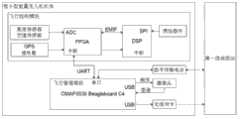
图2是视觉传感器节点结构连接图;Fig. 2 is a visual sensor node structural connection diagram;
图3是视觉传感器节点自主飞行实时控制模块的流程框架图;Fig. 3 is a process frame diagram of the autonomous flight real-time control module of the vision sensor node;
图4是视觉传感器节点飞行管理模块的流程框架图;Fig. 4 is the flow frame diagram of visual sensor node flight management module;
图5是视觉传感器节点的图像采集模块的流程框架图;Fig. 5 is the flow chart of the image acquisition module of visual sensor node;
图6是实时图像信息融合算法流程框架图;Fig. 6 is a flow chart of the real-time image information fusion algorithm;
图7是视觉传感器节点编队流程框架图;Fig. 7 is a framework diagram of visual sensor node formation process;
图8是视觉传感器阵列编队流程示意图;Fig. 8 is a schematic diagram of the visual sensor array formation process;
图9是视觉传感器阵列示意图。Fig. 9 is a schematic diagram of a visual sensor array.
具体实施方式Detailed ways
本发明中的无人机是指具有自主飞行、自主起降能力的微小型旋翼无人机。基于这种微小型旋翼无人机,采用特定飞行编队方式构建视觉传感阵列,通过各视觉传感节点协同工作采集和下传图像信息,地面站接收各视觉传感节点图像信息并进行实时融合,达到实时显示包含全部图像信息的目的。The unmanned aerial vehicle in the present invention refers to the miniature rotor unmanned aerial vehicle with autonomous flight, autonomous take-off and landing capabilities. Based on this kind of micro-rotor UAV, a visual sensor array is constructed by using a specific flight formation, and the image information is collected and downloaded through the cooperative work of each visual sensor node, and the ground station receives the image information of each visual sensor node and performs real-time fusion. , to achieve the purpose of displaying all image information in real time.
如图1所示,系统由多个视觉传感器节点、若干个第一级地面站和一个第二级地面站组成。三个视觉传感器节点组成一个组,与一个第一级地面站间通信采用无线方式通信,如图1中虚线所示,所有第一级地面站与第二级地面站采用有线以太网通信。As shown in Figure 1, the system consists of multiple visual sensor nodes, several first-level ground stations and a second-level ground station. Three visual sensor nodes form a group, and communicate with a first-level ground station by wireless communication, as shown by the dotted line in Figure 1, and all first-level ground stations communicate with the second-level ground station using wired Ethernet.
视觉传感器节点实现实时飞行控制、与第一级地面站通信触发视觉设备进行图像采集、图像信息回传第一级地面站等功能,视觉传感器节点的结构框图如图2,主要包括飞行控制模块、飞行管理模块、摄像头、数字传输电台、无线网卡和微小型旋翼无人机机体。飞行控制模块、飞行管理模块、摄像头、数字传输电台和无线网卡均固定在微小型旋翼无人机机体上,飞行控制模块、摄像头、数字传输电台和无线网卡均与飞行管理模块相连。视觉传感器节点通过数字传输电台发送飞行状态信息给第一级地面站,从第一级地面站接收指令;通过无线网卡发送图像数据到第一级地面站。The visual sensor node realizes real-time flight control, communicates with the first-level ground station to trigger the visual equipment to collect images, and sends image information back to the first-level ground station. The structural block diagram of the visual sensor node is shown in Figure 2, mainly including the flight control module, Flight management module, camera, digital transmission radio station, wireless network card and miniature rotor UAV body. The flight control module, flight management module, camera, digital transmission radio and wireless network card are all fixed on the body of the micro-rotor drone, and the flight control module, camera, digital transmission radio and wireless network card are all connected to the flight management module. The visual sensor node sends flight status information to the first-level ground station through the digital transmission station, and receives instructions from the first-level ground station; sends image data to the first-level ground station through the wireless network card.
飞行控制模块包括DSP、FPGA、惯性器件、GPS接收器、高度传感器和空速传感器。其中,GPS接收器、高度传感器和空速传感器均与FPGA相连,FPGA与DSP相连,惯性器件与DSP相连。飞行控制模块的作用是实时飞行控制,基于DSP+FPGA构架,DSP(Digital Signal Processor数字信号处理器)可以选用TI公司的TMS320C6713DSP处理器,FPGA(Field-Programmable Gate Array现场可编程门阵列)可以选用Xilinx公司的Spartan-3 XC3S1000芯片,但均不限于此。DSP作为主控制芯片,主要负责导航解算与飞行控制计算,同时其SPI接口挂载惯性器件读取飞行状态数据,惯性器件可选ADIS16405,但不限于此;FPGA作为协处理器,主要作为接口挂载与扩展,负责读取高度、空速等传感器值,挂载GPS接收器,并对串口扩展。DSP与FPGA之间使用EMIF接口进行通信。The flight control module includes DSP, FPGA, inertial devices, GPS receiver, altitude sensor and airspeed sensor. Among them, GPS receiver, altitude sensor and airspeed sensor are all connected with FPGA, FPGA is connected with DSP, and inertial device is connected with DSP. The function of the flight control module is real-time flight control. Based on the DSP+FPGA framework, DSP (Digital Signal Processor) can choose TI’s TMS320C6713DSP processor, and FPGA (Field-Programmable Gate Array) can choose Xilinx's Spartan-3 XC3S1000 chip, but not limited to this. As the main control chip, DSP is mainly responsible for navigation calculation and flight control calculation. At the same time, its SPI interface mounts inertial devices to read flight status data. The inertial devices can choose ADIS16405, but not limited to this; FPGA is used as a coprocessor, mainly as an interface Mounting and expansion, responsible for reading sensor values such as altitude and airspeed, mounting GPS receivers, and expanding the serial port. Use EMIF interface to communicate between DSP and FPGA.
飞行管理模块的作用是从第一级地面站接收指令,发送相应命令给飞行控制模块,同时从飞行控制模块接收飞行状态信息,触发摄像头采集图像并将采集到的图像回传第一级地面站。飞行管理模块可以选用TI公司基于OMAP3530芯片的BeagleBoard C4板,但不限于此。板上的一个串口接入数字传输电台,一个USB接口接入摄像头,另一USB接口接入无线网卡。飞行控制模块与飞行管理模块通过串口进行通信。The function of the flight management module is to receive instructions from the first-level ground station, send corresponding commands to the flight control module, and at the same time receive flight status information from the flight control module, trigger the camera to collect images and send the collected images back to the first-level ground station . The flight management module can use TI's BeagleBoard C4 board based on the OMAP3530 chip, but it is not limited to this. One serial port on the board is connected to the digital transmission radio station, one USB port is connected to the camera, and the other USB port is connected to the wireless network card. The flight control module communicates with the flight management module through the serial port.
摄像头负责采集图像,可以选用基于中星微zc301p芯片组的摄像头模组,数字传输电台负责与第一级地面站通信,可以选用利尔达LSDRF4710模组,工作频率为470MHz,无线网卡可以选用思科LINKSYS wusb54g V4无线网卡,微小型旋翼无人机机体可以选用XAircraft X650V-4飞行器。但均不限于此。The camera is responsible for collecting images, and the camera module based on Vimicro zc301p chipset can be selected. The digital transmission station is responsible for communicating with the first-level ground station. Lierda LSDRF4710 module can be used, and the working frequency is 470MHz. The wireless network card can be Cisco LINKSYS wusb54g V4 wireless network card, XAircraft X650V-4 aircraft can be used for the body of the micro-rotor drone. But neither is limited thereto.
第一级地面站和第二级地面站均由计算机来实现。第一级地面站通过数字传输电台向视觉传感器节点发送指令,通过无线网卡接收一组共三帧视觉传感器节点回传图像信息,并初步融合一组共三帧图像信息,将初步融合处理的图像信息传给第二级地面站。第一级地面站与第二级地面站通过以太网通信。第二级地面站实现接收由若干第一级地面站发送的经过初步融合处理的图像信息,并对所有初步融合的图像信息进行进一步图像信息融合,并实时显示包含所有图像信息的图像。Both the first-level ground station and the second-level ground station are implemented by computers. The first-level ground station sends instructions to the visual sensor nodes through the digital transmission station, receives a set of three frames of image information returned by the visual sensor nodes through the wireless network card, and initially fuses a set of three frames of image information, and the preliminary fusion processed image The information is passed to the second stage ground station. The first-level ground station communicates with the second-level ground station via Ethernet. The second-level ground station realizes receiving the image information sent by several first-level ground stations after preliminary fusion processing, and performs further image information fusion on all the initially fused image information, and displays the image containing all image information in real time.
本发明在上述系统上实现的实时图像信息融合方法,主要包括以下步骤:The real-time image information fusion method that the present invention realizes on above-mentioned system mainly comprises the following steps:
1、视觉传感器阵列初始化:包括视觉传感器阵列编队、视觉传感器节点层次结构构造、视觉传感器节点自主飞行到指定位置。1. Visual sensor array initialization: including visual sensor array formation, visual sensor node hierarchy structure, and visual sensor nodes autonomously flying to designated positions.
在实时图像信息融合之前,需要先布置视觉传感器节点阵列。如图7所示,节点初始由三个视觉传感器节点以等边三角形的形式排列,组成一个组与同一个第一级地面站通信,后续添加可由如图7所示的流程进行扩展。构造一个三叉树存储各节点层次关系,其构造流程如图8所示,得到视觉传感器节点阵列各节点位置,如图9所示。此项工作由第二级地面站完成,待第二级地面站完成布置节点后即向若干第一级地面站发送节点位置信息,再由第一级地面站向相应节点发送指令。各节点飞行管理模块接收到指令后,通知飞行控制模块,以如图3的方式自主控制该微小型旋翼无人机到达指定位置。Before real-time image information fusion, it is necessary to arrange the visual sensor node array. As shown in Figure 7, the nodes are initially arranged in the form of three visual sensor nodes in the form of an equilateral triangle, forming a group to communicate with the same first-level ground station, and subsequent additions can be expanded by the process shown in Figure 7. Construct a ternary tree to store the hierarchical relationship of each node. The construction process is shown in Figure 8, and the position of each node in the visual sensor node array is obtained, as shown in Figure 9. This work is done by the second-level ground station, and after the second-level ground station completes the arrangement of nodes, it will send node location information to several first-level ground stations, and then the first-level ground station will send instructions to the corresponding nodes. After receiving the instruction, the flight management module of each node notifies the flight control module to autonomously control the micro-rotor UAV to reach the designated position in the manner shown in Figure 3.
1.1视觉传感器阵列编队流程如图7所示:先对视觉传感器节点进行分组,以三个视觉传感器节点为一组,以等边三角形方式在空间中排列,等边三角形的边长与视觉传感器节点视场范围和高度相关,一组视觉传感器节点与同一第一级地面站通信,对同组上的各视觉传感器节点进行编码,记为A、B、C,根据一组由三个节点组成的特征,以三叉树表征视觉传感器阵列的结构;首先初始化一组视觉传感器节点,作为三叉树的顶点,后续视觉传感器节点添加以组为单位进行;判断当前视觉传感器节点数量是否满足视场范围与精度需求,若未满足,则按广度优先的原则如图8所示的方式,添加一组视觉传感器节点至三叉树中;否则停止添加视觉传感器节点,监测各节点是否异常,若出现异常则调度三叉树最右端节点替换异常节点,使得系统具有一定自修复能力,提高了系统的鲁棒性。1.1 The visual sensor array formation process is shown in Figure 7: first, the visual sensor nodes are grouped into groups of three visual sensor nodes, arranged in an equilateral triangle in space, and the side length of the equilateral triangle is the same as that of the visual sensor nodes. The range of field of view is related to the height. A group of visual sensor nodes communicates with the same first-level ground station, and encodes the visual sensor nodes on the same group, which are denoted as A, B, and C. According to a group of three nodes Features, the structure of the visual sensor array is represented by a ternary tree; first, a group of visual sensor nodes is initialized as the vertices of the ternary tree, and subsequent visual sensor nodes are added in units of groups; determine whether the current number of visual sensor nodes meets the range and accuracy of the field of view If the requirements are not met, add a group of visual sensor nodes to the ternary tree according to the breadth-first principle as shown in Figure 8; otherwise, stop adding visual sensor nodes, monitor whether each node is abnormal, and schedule the ternary tree if there is an abnormality The rightmost node of the tree replaces the abnormal node, which makes the system have a certain self-repair ability and improves the robustness of the system.
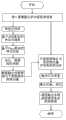
1.2视觉传感器节点层次结构以三叉树的形式构造,其构造流程如图8所示:1.2 The visual sensor node hierarchy is constructed in the form of a ternary tree, and its construction process is shown in Figure 8:
1) 先初始化一组视觉传感器节点,作为三叉树顶点并记代数为①,①代节点添加完成;1) Initialize a group of visual sensor nodes first, as the vertices of the ternary tree and record the algebra as ①, and the ① generation node is added;
2) 第二次向①的A支添加一个组共三个节点;2) Add a group of three nodes to branch A of ① for the second time;
3) 第三次向①的B支添加一个组共三个节点;3) For the third time, add a group of three nodes to branch B of ①;
4) 第四次向①的C支添加一个组共三个节点,至此②代的节点添加完成;4) For the fourth time, add a group of three nodes to branch C of ①, and the node addition of generation ② is completed;
5) 第五次按照代数为②的节点的添加方式向①代的A支的②代节点添加一个组;5) For the fifth time, add a group to the ② generation node of the A branch of the ① generation according to the addition method of the node whose algebra is ②;
6) 第六次依同样的方法向①代的B支的②代节点添加一个组,此时由于新添加组的A节点位置上已经另一节点占据,如虚线指向所示,则去掉此次添加的A支;6) For the sixth time, add a group to the ② generation node of the B branch of the ① generation in the same way. At this time, because the position of the A node of the newly added group is already occupied by another node, as shown by the dotted line, remove this time A branch added;
7) 第七次依同样的方法向①代的C支的②代节点添加一个组,此时由于新添加组的A、B节点位置上已经被其他节点占据,如虚线指向所示,则去掉此次添加的A、B支,至此③代节点添加完成;7) For the seventh time, add a group to the ② generation node of the C branch of the ① generation in the same way. At this time, because the positions of the A and B nodes of the newly added group have been occupied by other nodes, as shown by the dotted line, remove For the A and B branches added this time, the addition of ③ generation nodes is completed;
8) 此后添加依据上述规则进行。8) Subsequent additions are made according to the above rules.
1.3视觉传感器节点自主飞行到指定位置的任务主要由视觉传感器节点的飞行管理模块和飞行控制模块完成。1.3 The task of the visual sensor node autonomously flying to the designated position is mainly completed by the flight management module and the flight control module of the visual sensor node.
视觉传感器节点的飞行管理模块主要功能是分别与飞行控制模块和第一级地面站通信:从飞行控制模块获得飞行状态,设定飞行控制模块中飞行控制器高度、位置等参数;从第一级地面站接收飞行控制指令与图像采集命令,下传采集到的图像信息。飞行管理模块具体的流程如图4所示:飞行管理模块首先初始化串口、网络接口、摄像头等设备;然后循环查询接收第一级地面站的飞控指令,若收到停止指令,则自主规划航迹,自动降落返回地面,否则按飞控指令动作;若收到图像采集指令,则触发摄像头采集一帧图像,保存该帧图像并下传该帧图像至第一级地面站,否则重新等待接收第一级地面站指令。The main function of the flight management module of the visual sensor node is to communicate with the flight control module and the first-level ground station respectively: obtain the flight status from the flight control module, set the flight controller altitude, position and other parameters in the flight control module; The ground station receives flight control commands and image acquisition commands, and downloads the collected image information. The specific flow of the flight management module is shown in Figure 4: the flight management module first initializes the serial port, network interface, camera and other equipment; then circularly inquires and receives the flight control instructions from the first-level ground station, and if it receives a stop instruction, it will independently plan the flight If the image acquisition instruction is received, the camera will be triggered to collect a frame of image, save the frame of image and download the frame of image to the first-level ground station, otherwise wait for receiving again First level ground station command.
视觉传感器节点的飞行控制模块主要功能是实时飞行控制,具体流程如图3所示:先初始化飞行控制模块各接口,查询接收飞行管理模块指令;解码并根据指令更新高度、位置等控制器参数设定值;从高度传感器、空速传感器、惯性器件、GPS等传感器中采集飞行状态数据,进行基于EKF算法的导航解算、实时飞行控制计算,并将计算结果通过舵机输出完成对无人机的实时控制;若未收到停止指令,则重新查询接收飞行管理模块指令,否则无人机自主规划航迹,返回地面。The main function of the flight control module of the visual sensor node is real-time flight control. The specific process is shown in Figure 3: first initialize the interfaces of the flight control module, query and receive the instructions of the flight management module; decode and update the controller parameter settings such as altitude and position according to the instructions. Fixed value; collect flight status data from sensors such as altitude sensor, airspeed sensor, inertial device, GPS, etc., perform navigation calculation based on EKF algorithm, real-time flight control calculation, and output the calculation result through the steering gear to complete the control of the UAV. Real-time control; if no stop command is received, re-query and receive the flight management module command, otherwise the UAV will plan its own trajectory and return to the ground.
2、视觉传感器节点采集图像:包括视觉传感器节点接收图像采集指令、图像采集保存与下传。2. Image acquisition by visual sensor nodes: including receiving image acquisition instructions by visual sensor nodes, image acquisition, storage and downloading.
已经如图9所示建立视觉传感器阵列后,由第二级地面站告知第一级地面站在同一时间向节点发出图像采集指令。节点由数字传输电台接收图像采集指令后,飞行管理模块按照如图4的方式调度触发摄像头,以如图5的方式采集一帧图像并将该帧图像保存,由无线网卡传回第一级地面站。由于各个节点在同一时刻采集图像,可以保证各节点采集回来的图像是同步的,即包含同一时刻某一相同区域的图像信息。若干第一级地面站通过无线网卡接收对应的一组视觉传感器节点传回的三帧图像。After the visual sensor array has been established as shown in Fig. 9, the second-level ground station informs the first-level ground station to issue an image acquisition command to the nodes at the same time. After the node receives the image acquisition command from the digital transmission station, the flight management module dispatches and triggers the camera as shown in Figure 4, collects a frame of image as shown in Figure 5 and saves the frame, and transmits it back to the first-level ground by the wireless network card stand. Since each node collects images at the same time, it can be guaranteed that the images collected by each node are synchronous, that is, they contain image information of the same area at the same time. Several first-level ground stations receive three frames of images returned by a corresponding group of visual sensor nodes through wireless network cards.
2.1 视觉传感器节点接收图像采集指令由视觉传感器节点的飞行管理模块通过数字传输电台完成接收,如图4所示,当视觉传感器节点到达指定高度、位置时,若收到第一级地面站图像采集命令,则触发摄像头采集一帧图像。2.1 The image acquisition instruction received by the visual sensor node is received by the flight management module of the visual sensor node through the digital transmission station, as shown in Figure 4. command, the camera is triggered to capture a frame of image.
2.2 图像采集保存与下传由视觉传感器节点的飞行管理模块、摄像头、无线网卡共同完成,飞行管理模块收到图像采集指令即触发摄像头采集一帧图像并保存该图像,再通过无线网卡将该图像传回第一级地面站。图像采集的具体流程如图5所示:先打开视频设备并初始化,初始化包括设置摄像头支持标准、视频捕获格式、分配图像内存等;然后阻塞等待触发信号,等到触发信号到来,则获取当前帧图像缓存物理地址,并以地址映射的方式从缓存中读出该帧图像数据并保存,若接收到结束采集指令,则清空缓存,关闭视频设备,否则返回,重新阻塞等待触发信号。2.2 Image acquisition, storage and downloading are completed by the flight management module, camera, and wireless network card of the visual sensor node. The flight management module receives the image acquisition command and triggers the camera to capture a frame of image and save the image, and then passes the image through the wireless network card. Transmitted back to the first level ground station. The specific process of image acquisition is shown in Figure 5: first turn on the video device and initialize it. Initialization includes setting the camera support standard, video capture format, allocating image memory, etc.; then block and wait for the trigger signal, and then obtain the current frame image when the trigger signal arrives Cache the physical address, and read the frame of image data from the cache in the form of address mapping and save it. If the end capture command is received, the cache will be cleared and the video device will be turned off. Otherwise, it will return and block again to wait for the trigger signal.
3、图像信息融合:包括第一级地面站初步图像信息融合、第二级地面站进一步图像信息融合。3. Image information fusion: including preliminary image information fusion of the first-level ground station and further image information fusion of the second-level ground station.
第一级地面站接收完成其对应三帧图像后,按照如图6的方式进行初步图像信息融合,第一级地面站初步融合得到的图像通过以太网传递给第二级地面站。第二级地面站接收若干第一级地面站初步融合图像数据,按照如图6的方法进行进一步图像信息融合,得到包含全部图像信息的图像。After receiving the corresponding three frames of images, the first-level ground station performs preliminary image information fusion according to the method shown in Figure 6, and the image obtained by the preliminary fusion of the first-level ground station is transmitted to the second-level ground station through Ethernet. The second-level ground station receives the preliminary fusion image data of several first-level ground stations, performs further image information fusion according to the method shown in Figure 6, and obtains an image containing all image information.
第一级地面站与第二级地面站图像融合的方法均是基于ORB特征点提取实现,只是融合的图像信息不同,其具体步骤如图6所示:首先读入需要融合的多帧图像数据信息,暂时降低图像分辨率以快速获得图像变换矢量,采用ORB算法提取各各帧图像特征点,再由Flann算法进行特征点匹配,根据匹配结果优化、更新相机参数,在解算融合后图像相对于原图像的变换矢量;对原图像数据按特征提取匹配得到的变换矢量作变换,计算原图像各点新坐标,略去图像信息中冗余部分并对曝光进行补偿、修正,即可得到融合了多帧图像数据信息后的新图像。其中基于ORB算法的特征点提取是图像信息融合算法的关键,这直接影响到图像信息融合的准确性和实时性。ORB算法基于FAST和BRIEF算法,并在其基础上引入方向信息,能够快速、准确地给出图像特征描述,对图像具有旋转不变性,对噪声有良好的抑制效果。ORB算法的思路如下:The image fusion methods of the first-level ground station and the second-level ground station are based on the extraction of ORB feature points, but the fused image information is different. The specific steps are shown in Figure 6: First, read in the multi-frame image data that needs to be fused Information, temporarily reduce the image resolution to quickly obtain the image transformation vector, use the ORB algorithm to extract the image feature points of each frame, and then use the Flann algorithm to match the feature points, optimize and update the camera parameters according to the matching results, and after solving the fusion, the image is relatively Based on the transformation vector of the original image; transform the transformation vector obtained by feature extraction and matching of the original image data, calculate the new coordinates of each point in the original image, omit the redundant part of the image information and compensate and correct the exposure to obtain fusion A new image after obtaining multiple frames of image data information. Among them, the feature point extraction based on ORB algorithm is the key to the image information fusion algorithm, which directly affects the accuracy and real-time performance of image information fusion. The ORB algorithm is based on the FAST and BRIEF algorithms, and introduces direction information on the basis of it, which can quickly and accurately describe the image features, has rotation invariance to the image, and has a good suppression effect on noise. The idea of the ORB algorithm is as follows:
1) 用FAST特征点检测算子快速找出特征点;1) Use the FAST feature point detection operator to quickly find the feature points;
2) 用Harris角点检测方法选取前N个最优特征点,即关键点;2) Use the Harris corner detection method to select the first N optimal feature points, that is, the key points;
3) 用Intensity Centroid算法求解出关键点方向;3) Use the Intensity Centroid algorithm to solve the key point direction;
4) 将关键点的方向信息作为BRIEF算子的方向得到带方向信息的BRIEF特征,即ORB图像特征。4) Use the direction information of the key points as the direction of the BRIEF operator to obtain the BRIEF feature with direction information, that is, the ORB image feature.
4、视觉传感器阵列空间移动:第二级地面站指示视觉传感器阵列移动、重复步骤2-3的图像采集与融合过程。4. Spatial movement of the visual sensor array: the second-level ground station instructs the movement of the visual sensor array, and repeats the image acquisition and fusion process of steps 2-3.
4.1 待第二级地面站进一步完成图像信息融合实时显示后,重新由第二级地面站指示若干第一级地面站,通知各视觉传感器节点新的位置。4.1 After the second-level ground station further completes the real-time display of image information fusion, the second-level ground station will instruct several first-level ground stations again, and notify each visual sensor node of the new position.
4.2 待各传感器节点到达新的指定位置后,系统重复步骤2-3,各传感器节点采集图像传回相应第一级地面站初步融合处理,再由第二级地面站接收若干第一级地面站初步融合结果做进一步融合、显示。4.2 After each sensor node arrives at the new designated location, the system repeats steps 2-3. The images collected by each sensor node are sent back to the corresponding first-level ground station for preliminary fusion processing, and then the second-level ground station receives several first-level ground stations. The preliminary fusion results are further fused and displayed.
Claims (6)
Translated fromChinesePriority Applications (1)
| Application Number | Priority Date | Filing Date | Title |
|---|---|---|---|
| CN201210483500.6ACN102967297B (en) | 2012-11-23 | 2012-11-23 | Space movable visual sensor array system and image information fusion method |
Applications Claiming Priority (1)
| Application Number | Priority Date | Filing Date | Title |
|---|---|---|---|
| CN201210483500.6ACN102967297B (en) | 2012-11-23 | 2012-11-23 | Space movable visual sensor array system and image information fusion method |
Publications (2)
| Publication Number | Publication Date |
|---|---|
| CN102967297Atrue CN102967297A (en) | 2013-03-13 |
| CN102967297B CN102967297B (en) | 2014-01-29 |
Family
ID=47797599
Family Applications (1)
| Application Number | Title | Priority Date | Filing Date |
|---|---|---|---|
| CN201210483500.6AExpired - Fee RelatedCN102967297B (en) | 2012-11-23 | 2012-11-23 | Space movable visual sensor array system and image information fusion method |
Country Status (1)
| Country | Link |
|---|---|
| CN (1) | CN102967297B (en) |
Cited By (10)
| Publication number | Priority date | Publication date | Assignee | Title |
|---|---|---|---|---|
| CN104168455A (en)* | 2014-08-08 | 2014-11-26 | 北京航天控制仪器研究所 | Air-based large-scene photographing system and method |
| CN104202559A (en)* | 2014-08-11 | 2014-12-10 | 广州中大数字家庭工程技术研究中心有限公司 | Intelligent monitoring system and intelligent monitoring method based on rotation invariant feature |
| CN104777847A (en)* | 2014-01-13 | 2015-07-15 | 中南大学 | Unmanned aerial vehicle target tracking system based on machine vision and ultra-wideband positioning technology |
| CN104994355A (en)* | 2015-07-14 | 2015-10-21 | 杨珊珊 | Intelligent active image acquisition and update system and method |
| CN105791780A (en)* | 2015-04-02 | 2016-07-20 | 李勇 | Transmission device identification platform located on unmanned aerial vehicle |
| CN105953796A (en)* | 2016-05-23 | 2016-09-21 | 北京暴风魔镜科技有限公司 | Stable motion tracking method and stable motion tracking device based on integration of simple camera and IMU (inertial measurement unit) of smart cellphone |
| CN105974932A (en)* | 2016-04-27 | 2016-09-28 | 中国人民解放军装甲兵工程学院 | Unmanned aerial vehicle control method |
| CN106909877A (en)* | 2016-12-13 | 2017-06-30 | 浙江大学 | A kind of vision based on dotted line comprehensive characteristics builds figure and localization method simultaneously |
| CN106990789A (en)* | 2017-04-11 | 2017-07-28 | 北京机械设备研究所 | A kind of rapid reconnaissance method of special environment Reconnaissance system and special environment |
| CN109120900A (en)* | 2018-09-17 | 2019-01-01 | 武汉卓尔无人机制造有限公司 | Unmanned vehicle images processing system and its processing method |
Citations (14)
| Publication number | Priority date | Publication date | Assignee | Title |
|---|---|---|---|---|
| US20020085094A1 (en)* | 1997-04-08 | 2002-07-04 | Teuchert Wolf Dieter | Photogrammetric camera |
| EP1241441A2 (en)* | 2001-03-13 | 2002-09-18 | EMT Ingenieurbüro für Elektro-Mechanische Technologien Dipl.-Ing. Hartmut Euer | Method and apparatus for the recording of aerial images for aerial reconnaissance |
| CN1555637A (en)* | 1999-05-28 | 2004-12-15 | �Դ���� | Wireless transceiver network using node-to-node data messaging |
| CN101001186A (en)* | 2006-11-29 | 2007-07-18 | 程伟明 | Monitoring system based on sensor-based network technology |
| US20070188653A1 (en)* | 2006-02-13 | 2007-08-16 | Pollock David B | Multi-lens array system and method |
| CN101035017A (en)* | 2007-02-02 | 2007-09-12 | 南京邮电大学 | Distributed management method for the radio sensor network based on the mobile agent |
| CN200993579Y (en)* | 2006-11-09 | 2007-12-19 | 智基科技开发股份有限公司 | Image navigation device |
| CN101815368A (en)* | 2010-03-08 | 2010-08-25 | 南昌航空大学 | Tactical exercise decision assistant system based on wireless sensor network |
| CN101949709A (en)* | 2010-08-19 | 2011-01-19 | 中国测绘科学研究院 | Onboard GPS aerial photography navigation control system and control method thereof |
| US20110069145A1 (en)* | 2008-02-28 | 2011-03-24 | Bae Systems Information And Electronic Systems Integration, Inc. | Method and system for finding a manpads launcher position |
| EP2487909A1 (en)* | 2011-02-10 | 2012-08-15 | BAE Systems PLC | Image capturing |
| CN102668534A (en)* | 2009-10-19 | 2012-09-12 | 图形科技公司 | Data search, parsing and synchronization of video and telemetry data |
| CN202494448U (en)* | 2012-02-24 | 2012-10-17 | 黄克明 | Synchronous acquiring device of aerial photo data |
| CN202551195U (en)* | 2012-05-16 | 2012-11-21 | 广东美嘉欣玩具有限公司 | Control device for aerial photographing and videoing |
- 2012
- 2012-11-23CNCN201210483500.6Apatent/CN102967297B/ennot_activeExpired - Fee Related
Patent Citations (14)
| Publication number | Priority date | Publication date | Assignee | Title |
|---|---|---|---|---|
| US20020085094A1 (en)* | 1997-04-08 | 2002-07-04 | Teuchert Wolf Dieter | Photogrammetric camera |
| CN1555637A (en)* | 1999-05-28 | 2004-12-15 | �Դ���� | Wireless transceiver network using node-to-node data messaging |
| EP1241441A2 (en)* | 2001-03-13 | 2002-09-18 | EMT Ingenieurbüro für Elektro-Mechanische Technologien Dipl.-Ing. Hartmut Euer | Method and apparatus for the recording of aerial images for aerial reconnaissance |
| US20070188653A1 (en)* | 2006-02-13 | 2007-08-16 | Pollock David B | Multi-lens array system and method |
| CN200993579Y (en)* | 2006-11-09 | 2007-12-19 | 智基科技开发股份有限公司 | Image navigation device |
| CN101001186A (en)* | 2006-11-29 | 2007-07-18 | 程伟明 | Monitoring system based on sensor-based network technology |
| CN101035017A (en)* | 2007-02-02 | 2007-09-12 | 南京邮电大学 | Distributed management method for the radio sensor network based on the mobile agent |
| US20110069145A1 (en)* | 2008-02-28 | 2011-03-24 | Bae Systems Information And Electronic Systems Integration, Inc. | Method and system for finding a manpads launcher position |
| CN102668534A (en)* | 2009-10-19 | 2012-09-12 | 图形科技公司 | Data search, parsing and synchronization of video and telemetry data |
| CN101815368A (en)* | 2010-03-08 | 2010-08-25 | 南昌航空大学 | Tactical exercise decision assistant system based on wireless sensor network |
| CN101949709A (en)* | 2010-08-19 | 2011-01-19 | 中国测绘科学研究院 | Onboard GPS aerial photography navigation control system and control method thereof |
| EP2487909A1 (en)* | 2011-02-10 | 2012-08-15 | BAE Systems PLC | Image capturing |
| CN202494448U (en)* | 2012-02-24 | 2012-10-17 | 黄克明 | Synchronous acquiring device of aerial photo data |
| CN202551195U (en)* | 2012-05-16 | 2012-11-21 | 广东美嘉欣玩具有限公司 | Control device for aerial photographing and videoing |
Non-Patent Citations (3)
| Title |
|---|
| 李雪松,等: "基于鲁棒时变卡尔漫滤波估计的无人机视觉编队", 《应用科学学报》* |
| 李雪松,等: "无人机鲁棒反推自适应编队导引控制设计", 《应用科学学报》* |
| 范保杰,等: "旋翼无人机视觉跟踪系统", 《红外与激光工程》* |
Cited By (14)
| Publication number | Priority date | Publication date | Assignee | Title |
|---|---|---|---|---|
| CN104777847A (en)* | 2014-01-13 | 2015-07-15 | 中南大学 | Unmanned aerial vehicle target tracking system based on machine vision and ultra-wideband positioning technology |
| CN104168455B (en)* | 2014-08-08 | 2018-03-09 | 北京航天控制仪器研究所 | A kind of space base large scene camera system and method |
| CN104168455A (en)* | 2014-08-08 | 2014-11-26 | 北京航天控制仪器研究所 | Air-based large-scene photographing system and method |
| CN104202559A (en)* | 2014-08-11 | 2014-12-10 | 广州中大数字家庭工程技术研究中心有限公司 | Intelligent monitoring system and intelligent monitoring method based on rotation invariant feature |
| CN105791780A (en)* | 2015-04-02 | 2016-07-20 | 李勇 | Transmission device identification platform located on unmanned aerial vehicle |
| CN104994355A (en)* | 2015-07-14 | 2015-10-21 | 杨珊珊 | Intelligent active image acquisition and update system and method |
| CN105974932A (en)* | 2016-04-27 | 2016-09-28 | 中国人民解放军装甲兵工程学院 | Unmanned aerial vehicle control method |
| CN105974932B (en)* | 2016-04-27 | 2018-11-09 | 中国人民解放军装甲兵工程学院 | Unmanned aerial vehicle (UAV) control method |
| CN105953796A (en)* | 2016-05-23 | 2016-09-21 | 北京暴风魔镜科技有限公司 | Stable motion tracking method and stable motion tracking device based on integration of simple camera and IMU (inertial measurement unit) of smart cellphone |
| CN106909877A (en)* | 2016-12-13 | 2017-06-30 | 浙江大学 | A kind of vision based on dotted line comprehensive characteristics builds figure and localization method simultaneously |
| CN106909877B (en)* | 2016-12-13 | 2020-04-14 | 浙江大学 | A Visual Simultaneous Mapping and Positioning Method Based on the Comprehensive Features of Points and Lines |
| CN106990789A (en)* | 2017-04-11 | 2017-07-28 | 北京机械设备研究所 | A kind of rapid reconnaissance method of special environment Reconnaissance system and special environment |
| CN109120900A (en)* | 2018-09-17 | 2019-01-01 | 武汉卓尔无人机制造有限公司 | Unmanned vehicle images processing system and its processing method |
| CN109120900B (en)* | 2018-09-17 | 2019-05-24 | 武汉卓尔无人机制造有限公司 | Unmanned vehicle images processing system and its processing method |
Also Published As
| Publication number | Publication date |
|---|---|
| CN102967297B (en) | 2014-01-29 |
Similar Documents
| Publication | Publication Date | Title |
|---|---|---|
| CN102967297B (en) | Space movable visual sensor array system and image information fusion method | |
| JP6885485B2 (en) | Systems and methods for capturing still and / or moving scenes using multiple camera networks | |
| CN105828345B (en) | Ground-air wireless sensor network communication device and method compatible with UAV | |
| CN112789672B (en) | Control and navigation system, gesture optimization, mapping and positioning techniques | |
| CN103942273B (en) | A kind of aerial quick response dynamic monitoring system and its dynamic monitoring method | |
| CN112461210B (en) | An open-ground collaborative building surveying and mapping robot system and its surveying and mapping method | |
| CN108881825A (en) | Rice weed monitoring unmanned system and its monitoring method based on Jetson TK1 | |
| CN109792951B (en) | Unmanned aerial vehicle air route correction system for pollination of hybrid rice and correction method thereof | |
| CN110494360A (en) | For providing the autonomous system and method photographed and image | |
| CN106931963A (en) | Environmental data shared platform, unmanned vehicle, localization method and alignment system | |
| JP2017537484A (en) | System and method for detecting and tracking movable objects | |
| CN104977912A (en) | Ethernet-exchange-bus-based unmanned plane flight control system and method | |
| US20200111373A1 (en) | Autonomous mission action alteration | |
| CN102156481A (en) | Intelligent tracking control method and system for unmanned aerial vehicles | |
| US11611700B2 (en) | Unmanned aerial vehicle with virtual un-zoomed imaging | |
| CN114115289A (en) | An autonomous unmanned swarm reconnaissance system | |
| CN107943067A (en) | A kind of unmanned plane formation method, apparatus and system based on clustered control | |
| CN107291092A (en) | A kind of air-ground coordination UAS of WiFi supports | |
| Liang et al. | Design and development of ground control system for tethered uav | |
| WO2021088683A1 (en) | Method for adjusting self-discharge cycle of battery, and unmanned aerial vehicle | |
| CN105718867A (en) | Urban air streetscape processing system and method based on navigation airship | |
| CN119854761A (en) | Unmanned aerial vehicle and ground robot collaborative phenotype acquisition system | |
| CN205921694U (en) | Unmanned aerial vehicle aerial image collection system | |
| CN205080435U (en) | Control server, unmanned aerial vehicle and streetscape map making devices | |
| CN110073403A (en) | Image output generation method, equipment and unmanned plane |
Legal Events
| Date | Code | Title | Description |
|---|---|---|---|
| C06 | Publication | ||
| PB01 | Publication | ||
| C10 | Entry into substantive examination | ||
| SE01 | Entry into force of request for substantive examination | ||
| C14 | Grant of patent or utility model | ||
| GR01 | Patent grant | ||
| CF01 | Termination of patent right due to non-payment of annual fee | Granted publication date:20140129 Termination date:20141123 | |
| EXPY | Termination of patent right or utility model |