CN102958472A - Medical stent - Google Patents
Medical stentDownload PDFInfo
- Publication number
- CN102958472A CN102958472ACN2011800290259ACN201180029025ACN102958472ACN 102958472 ACN102958472 ACN 102958472ACN 2011800290259 ACN2011800290259 ACN 2011800290259ACN 201180029025 ACN201180029025 ACN 201180029025ACN 102958472 ACN102958472 ACN 102958472A
- Authority
- CN
- China
- Prior art keywords
- mentioned
- resin material
- outer peripheral
- outer layer
- coil
- Prior art date
- Legal status (The legal status is an assumption and is not a legal conclusion. Google has not performed a legal analysis and makes no representation as to the accuracy of the status listed.)
- Granted
Links
Images


Classifications
- A—HUMAN NECESSITIES
- A61—MEDICAL OR VETERINARY SCIENCE; HYGIENE
- A61F—FILTERS IMPLANTABLE INTO BLOOD VESSELS; PROSTHESES; DEVICES PROVIDING PATENCY TO, OR PREVENTING COLLAPSING OF, TUBULAR STRUCTURES OF THE BODY, e.g. STENTS; ORTHOPAEDIC, NURSING OR CONTRACEPTIVE DEVICES; FOMENTATION; TREATMENT OR PROTECTION OF EYES OR EARS; BANDAGES, DRESSINGS OR ABSORBENT PADS; FIRST-AID KITS
- A61F2/00—Filters implantable into blood vessels; Prostheses, i.e. artificial substitutes or replacements for parts of the body; Appliances for connecting them with the body; Devices providing patency to, or preventing collapsing of, tubular structures of the body, e.g. stents
- A61F2/82—Devices providing patency to, or preventing collapsing of, tubular structures of the body, e.g. stents
- A61F2/848—Devices providing patency to, or preventing collapsing of, tubular structures of the body, e.g. stents having means for fixation to the vessel wall, e.g. barbs
- A—HUMAN NECESSITIES
- A61—MEDICAL OR VETERINARY SCIENCE; HYGIENE
- A61L—METHODS OR APPARATUS FOR STERILISING MATERIALS OR OBJECTS IN GENERAL; DISINFECTION, STERILISATION OR DEODORISATION OF AIR; CHEMICAL ASPECTS OF BANDAGES, DRESSINGS, ABSORBENT PADS OR SURGICAL ARTICLES; MATERIALS FOR BANDAGES, DRESSINGS, ABSORBENT PADS OR SURGICAL ARTICLES
- A61L27/00—Materials for grafts or prostheses or for coating grafts or prostheses
- A61L27/40—Composite materials, i.e. containing one material dispersed in a matrix of the same or different material
- A61L27/42—Composite materials, i.e. containing one material dispersed in a matrix of the same or different material having an inorganic matrix
- A61L27/425—Composite materials, i.e. containing one material dispersed in a matrix of the same or different material having an inorganic matrix of phosphorus containing material, e.g. apatite
- A—HUMAN NECESSITIES
- A61—MEDICAL OR VETERINARY SCIENCE; HYGIENE
- A61L—METHODS OR APPARATUS FOR STERILISING MATERIALS OR OBJECTS IN GENERAL; DISINFECTION, STERILISATION OR DEODORISATION OF AIR; CHEMICAL ASPECTS OF BANDAGES, DRESSINGS, ABSORBENT PADS OR SURGICAL ARTICLES; MATERIALS FOR BANDAGES, DRESSINGS, ABSORBENT PADS OR SURGICAL ARTICLES
- A61L31/00—Materials for other surgical articles, e.g. stents, stent-grafts, shunts, surgical drapes, guide wires, materials for adhesion prevention, occluding devices, surgical gloves, tissue fixation devices
- A61L31/04—Macromolecular materials
- A61L31/048—Macromolecular materials obtained by reactions only involving carbon-to-carbon unsaturated bonds
- A—HUMAN NECESSITIES
- A61—MEDICAL OR VETERINARY SCIENCE; HYGIENE
- A61L—METHODS OR APPARATUS FOR STERILISING MATERIALS OR OBJECTS IN GENERAL; DISINFECTION, STERILISATION OR DEODORISATION OF AIR; CHEMICAL ASPECTS OF BANDAGES, DRESSINGS, ABSORBENT PADS OR SURGICAL ARTICLES; MATERIALS FOR BANDAGES, DRESSINGS, ABSORBENT PADS OR SURGICAL ARTICLES
- A61L31/00—Materials for other surgical articles, e.g. stents, stent-grafts, shunts, surgical drapes, guide wires, materials for adhesion prevention, occluding devices, surgical gloves, tissue fixation devices
- A61L31/04—Macromolecular materials
- A61L31/06—Macromolecular materials obtained otherwise than by reactions only involving carbon-to-carbon unsaturated bonds
- A—HUMAN NECESSITIES
- A61—MEDICAL OR VETERINARY SCIENCE; HYGIENE
- A61F—FILTERS IMPLANTABLE INTO BLOOD VESSELS; PROSTHESES; DEVICES PROVIDING PATENCY TO, OR PREVENTING COLLAPSING OF, TUBULAR STRUCTURES OF THE BODY, e.g. STENTS; ORTHOPAEDIC, NURSING OR CONTRACEPTIVE DEVICES; FOMENTATION; TREATMENT OR PROTECTION OF EYES OR EARS; BANDAGES, DRESSINGS OR ABSORBENT PADS; FIRST-AID KITS
- A61F2/00—Filters implantable into blood vessels; Prostheses, i.e. artificial substitutes or replacements for parts of the body; Appliances for connecting them with the body; Devices providing patency to, or preventing collapsing of, tubular structures of the body, e.g. stents
- A61F2/82—Devices providing patency to, or preventing collapsing of, tubular structures of the body, e.g. stents
- A61F2/86—Stents in a form characterised by the wire-like elements; Stents in the form characterised by a net-like or mesh-like structure
- A61F2/88—Stents in a form characterised by the wire-like elements; Stents in the form characterised by a net-like or mesh-like structure the wire-like elements formed as helical or spiral coils
- A—HUMAN NECESSITIES
- A61—MEDICAL OR VETERINARY SCIENCE; HYGIENE
- A61F—FILTERS IMPLANTABLE INTO BLOOD VESSELS; PROSTHESES; DEVICES PROVIDING PATENCY TO, OR PREVENTING COLLAPSING OF, TUBULAR STRUCTURES OF THE BODY, e.g. STENTS; ORTHOPAEDIC, NURSING OR CONTRACEPTIVE DEVICES; FOMENTATION; TREATMENT OR PROTECTION OF EYES OR EARS; BANDAGES, DRESSINGS OR ABSORBENT PADS; FIRST-AID KITS
- A61F2/00—Filters implantable into blood vessels; Prostheses, i.e. artificial substitutes or replacements for parts of the body; Appliances for connecting them with the body; Devices providing patency to, or preventing collapsing of, tubular structures of the body, e.g. stents
- A61F2/82—Devices providing patency to, or preventing collapsing of, tubular structures of the body, e.g. stents
- A61F2/94—Stents retaining their form, i.e. not being deformable, after placement in the predetermined place
- A—HUMAN NECESSITIES
- A61—MEDICAL OR VETERINARY SCIENCE; HYGIENE
- A61F—FILTERS IMPLANTABLE INTO BLOOD VESSELS; PROSTHESES; DEVICES PROVIDING PATENCY TO, OR PREVENTING COLLAPSING OF, TUBULAR STRUCTURES OF THE BODY, e.g. STENTS; ORTHOPAEDIC, NURSING OR CONTRACEPTIVE DEVICES; FOMENTATION; TREATMENT OR PROTECTION OF EYES OR EARS; BANDAGES, DRESSINGS OR ABSORBENT PADS; FIRST-AID KITS
- A61F2/00—Filters implantable into blood vessels; Prostheses, i.e. artificial substitutes or replacements for parts of the body; Appliances for connecting them with the body; Devices providing patency to, or preventing collapsing of, tubular structures of the body, e.g. stents
- A61F2/02—Prostheses implantable into the body
- A61F2/04—Hollow or tubular parts of organs, e.g. bladders, tracheae, bronchi or bile ducts
- A61F2002/041—Bile ducts
- A—HUMAN NECESSITIES
- A61—MEDICAL OR VETERINARY SCIENCE; HYGIENE
- A61F—FILTERS IMPLANTABLE INTO BLOOD VESSELS; PROSTHESES; DEVICES PROVIDING PATENCY TO, OR PREVENTING COLLAPSING OF, TUBULAR STRUCTURES OF THE BODY, e.g. STENTS; ORTHOPAEDIC, NURSING OR CONTRACEPTIVE DEVICES; FOMENTATION; TREATMENT OR PROTECTION OF EYES OR EARS; BANDAGES, DRESSINGS OR ABSORBENT PADS; FIRST-AID KITS
- A61F2/00—Filters implantable into blood vessels; Prostheses, i.e. artificial substitutes or replacements for parts of the body; Appliances for connecting them with the body; Devices providing patency to, or preventing collapsing of, tubular structures of the body, e.g. stents
- A61F2/02—Prostheses implantable into the body
- A61F2/04—Hollow or tubular parts of organs, e.g. bladders, tracheae, bronchi or bile ducts
- A61F2/06—Blood vessels
- A61F2/07—Stent-grafts
- A61F2002/072—Encapsulated stents, e.g. wire or whole stent embedded in lining
- A—HUMAN NECESSITIES
- A61—MEDICAL OR VETERINARY SCIENCE; HYGIENE
- A61F—FILTERS IMPLANTABLE INTO BLOOD VESSELS; PROSTHESES; DEVICES PROVIDING PATENCY TO, OR PREVENTING COLLAPSING OF, TUBULAR STRUCTURES OF THE BODY, e.g. STENTS; ORTHOPAEDIC, NURSING OR CONTRACEPTIVE DEVICES; FOMENTATION; TREATMENT OR PROTECTION OF EYES OR EARS; BANDAGES, DRESSINGS OR ABSORBENT PADS; FIRST-AID KITS
- A61F2/00—Filters implantable into blood vessels; Prostheses, i.e. artificial substitutes or replacements for parts of the body; Appliances for connecting them with the body; Devices providing patency to, or preventing collapsing of, tubular structures of the body, e.g. stents
- A61F2/82—Devices providing patency to, or preventing collapsing of, tubular structures of the body, e.g. stents
- A61F2/848—Devices providing patency to, or preventing collapsing of, tubular structures of the body, e.g. stents having means for fixation to the vessel wall, e.g. barbs
- A61F2002/8483—Barbs
- A—HUMAN NECESSITIES
- A61—MEDICAL OR VETERINARY SCIENCE; HYGIENE
- A61F—FILTERS IMPLANTABLE INTO BLOOD VESSELS; PROSTHESES; DEVICES PROVIDING PATENCY TO, OR PREVENTING COLLAPSING OF, TUBULAR STRUCTURES OF THE BODY, e.g. STENTS; ORTHOPAEDIC, NURSING OR CONTRACEPTIVE DEVICES; FOMENTATION; TREATMENT OR PROTECTION OF EYES OR EARS; BANDAGES, DRESSINGS OR ABSORBENT PADS; FIRST-AID KITS
- A61F2220/00—Fixations or connections for prostheses classified in groups A61F2/00 - A61F2/26 or A61F2/82 or A61F9/00 or A61F11/00 or subgroups thereof
- A61F2220/0025—Connections or couplings between prosthetic parts, e.g. between modular parts; Connecting elements
- A61F2220/0058—Connections or couplings between prosthetic parts, e.g. between modular parts; Connecting elements soldered or brazed or welded
- A—HUMAN NECESSITIES
- A61—MEDICAL OR VETERINARY SCIENCE; HYGIENE
- A61F—FILTERS IMPLANTABLE INTO BLOOD VESSELS; PROSTHESES; DEVICES PROVIDING PATENCY TO, OR PREVENTING COLLAPSING OF, TUBULAR STRUCTURES OF THE BODY, e.g. STENTS; ORTHOPAEDIC, NURSING OR CONTRACEPTIVE DEVICES; FOMENTATION; TREATMENT OR PROTECTION OF EYES OR EARS; BANDAGES, DRESSINGS OR ABSORBENT PADS; FIRST-AID KITS
- A61F2250/00—Special features of prostheses classified in groups A61F2/00 - A61F2/26 or A61F2/82 or A61F9/00 or A61F11/00 or subgroups thereof
- A61F2250/0014—Special features of prostheses classified in groups A61F2/00 - A61F2/26 or A61F2/82 or A61F9/00 or A61F11/00 or subgroups thereof having different values of a given property or geometrical feature, e.g. mechanical property or material property, at different locations within the same prosthesis
- A61F2250/0046—Special features of prostheses classified in groups A61F2/00 - A61F2/26 or A61F2/82 or A61F9/00 or A61F11/00 or subgroups thereof having different values of a given property or geometrical feature, e.g. mechanical property or material property, at different locations within the same prosthesis differing in melting temperature
Landscapes
- Health & Medical Sciences (AREA)
- Chemical & Material Sciences (AREA)
- Veterinary Medicine (AREA)
- Life Sciences & Earth Sciences (AREA)
- Animal Behavior & Ethology (AREA)
- General Health & Medical Sciences (AREA)
- Public Health (AREA)
- Heart & Thoracic Surgery (AREA)
- Engineering & Computer Science (AREA)
- Vascular Medicine (AREA)
- Epidemiology (AREA)
- Oral & Maxillofacial Surgery (AREA)
- Surgery (AREA)
- Chemical Kinetics & Catalysis (AREA)
- Transplantation (AREA)
- Biomedical Technology (AREA)
- Inorganic Chemistry (AREA)
- Composite Materials (AREA)
- Materials Engineering (AREA)
- Dermatology (AREA)
- Medicinal Chemistry (AREA)
- Cardiology (AREA)
- Media Introduction/Drainage Providing Device (AREA)
- Materials For Medical Uses (AREA)
Abstract
Translated fromChineseDescription
Translated fromChinese技术领域technical field
本发明涉及一种医用支架。本申请基于2010年10月29日在日本提出申请的日本特愿2010-244230号而主张优先权,并在此引用其内容。The invention relates to a medical bracket. this application claims priority based on Japanese Patent Application No. 2010-244230 for which it applied to Japan on October 29, 2010, and uses the content here.
背景技术Background technique
以往,针对形成于血管、消化管、胆管等活体内管腔的狭窄部,为了使该狭窄部扩张并维持持续张开状态而进行医用支架(以下,也称作“支架”)的留置。Conventionally, medical stents (hereinafter, also referred to as "stents") have been indwelled in narrowed portions formed in lumens of living bodies such as blood vessels, digestive tracts, and bile ducts in order to expand the narrowed portion and maintain the open state.
其中,例如,专利文献1所示的在胆管中使用的支架形成为大致管状。在该支架的顶端侧与基端侧分别设有能够以在自然状态下打开并且在预定的外力作用下闭合的方式变形的挡片(弹性构件)。挡片是通过对支架主体(外部层)的外表面所使用的树脂制的构件进行切割并使其竖起而形成的。Among them, for example, the stent used in the bile duct disclosed in Patent Document 1 is formed in a substantially tubular shape. A flap (elastic member) capable of being deformed so as to open in a natural state and close under a predetermined external force is respectively provided on the front end side and the base end side of the bracket. The flap is formed by cutting and erecting a resin member used for the outer surface of the bracket main body (outer layer).
这些挡片卡定于十二指肠乳头的入口与胆管的狭窄部的出口处而用于将支架固定于狭窄部。而且,利用支架中卡定于十二指肠乳头的入口处的部分来回收支架。These baffles are locked at the entrance of the duodenal papilla and the exit of the narrow part of the bile duct for fixing the bracket to the narrow part. Furthermore, the stent is retrieved using the part of the stent caught at the entrance of the duodenal papilla.
专利文献2所示的其他结构的支架虽不具备挡片,但是通过连接多种材料而构成支架。该支架包括支架主体、覆盖树脂层及筒状罩,该支架主体形成为大致圆筒状且形成有多个开口;该覆盖树脂层配置在支架主体的内腔且由多孔性树脂薄膜形成;该筒状罩连接支架主体和覆盖树脂层。The bracket of other structures shown in
筒状罩由与多孔性树脂之间不具有粘接性的加热固化型树脂等形成。为了提高支架主体与加热固化型树脂之间的粘接性而对支架主体实施预处理。通过在使将加热固化型树脂溶解于有机溶剂而得到的溶解液流入到形成于多孔性树脂薄膜的细孔内之后进行固化,从而将筒状罩连接于覆盖树脂层。The cylindrical cover is formed of heat-curable resin or the like that does not have adhesiveness with porous resin. The stent main body is pretreated in order to improve the adhesiveness between the stent main body and the heat-curable resin. The cylindrical cover is connected to the covering resin layer by allowing a solution obtained by dissolving a heat-curable resin in an organic solvent to flow into the pores formed in the porous resin film and then curing it.
另外,专利文献3所记载的支架移植片虽也不具备挡片,但是利用硅酮粘接剂将形成为管状的网格构件与以覆盖网格构件的外周面的方式配置的套筒连接起来。In addition, the stent-graft described in
专利文献1:日本特开2006-87712号公报Patent Document 1: Japanese Patent Laid-Open No. 2006-87712
专利文献2:日本特开2005-278993号公报Patent Document 2: Japanese Unexamined Patent Publication No. 2005-278993
专利文献3:日本特开平10-305050号公报Patent Document 3: Japanese Patent Application Laid-Open No. 10-305050
在专利文献1所记载的支架中,主体的外表面所使用的树脂与挡片由相同的材料形成。在欲调节主体与挡片的硬度的情况等,利用专利文献2或专利文献3所记载的方法将由与主体不同的材料形成的挡片连接于该主体。In the bracket described in Patent Document 1, the resin used for the outer surface of the main body is formed of the same material as the shutter piece. When it is desired to adjust the hardness of the main body and the flap, a flap made of a material different from that of the main body is connected to the main body by the method described in
但是,在如专利文献2所公开的支架那样连接覆盖树脂层与筒状罩的情况下,若减小形成于覆盖树脂层的细孔的内径,则存在两个构件的连接强度降低的可能性。另一方面,当细孔的内径变大时,由于覆盖构件通常形成地较薄,因此存在覆盖树脂层的强度降低的可能性。However, in the case of connecting the covering resin layer and the cylindrical cover like the stent disclosed in
另外,若如专利文献3所记载的支架移植片那样利用粘接剂连接两个构件,则存在被连接的部分硬化的可能性。因此,在如挡片与主体那样使两个构件中的一方相对于另一方反复移动的情况下,存在挡片因硬化了的部分而难以相对于主体移动,对安装有支架移植片的活体造成负担的可能性。In addition, when two members are connected with an adhesive like the stent-graft described in
发明内容Contents of the invention
本发明的目的在于提供一种医用支架,在该医用支架中,利用与外部层不同的材料形成弹性构件,并且通过防止弹性构件与外部层之间的连接部硬化而使弹性构件可靠地连接于外部层。An object of the present invention is to provide a medical stent in which an elastic member is formed using a material different from that of the outer layer, and the elastic member is reliably connected to the outer layer.
根据本发明的一个技术方案,该医用支架包括:线圈,其通过使线材绕预定的轴线进行卷绕而形成;外部层,其由第一树脂材料形成为大致管状,且与上述线圈同轴地设置在上述线圈的外周侧;内部层,其形成为大致管状,且与上述线圈同轴地设置在上述线圈的内周侧;以及弹性构件,其由与上述第一树脂材料不同的第二树脂材料形成,该弹性构件形成为使形成于一端侧的外周面的表面处理部与上述外部层的端部的外周面接触而进行固定,并且另一端沿着上述轴线向上述外部层的中央部侧延伸并向上述外部层的径向外侧打开;上述第二树脂材料的熔化温度比上述第一树脂材料的熔化温度高,上述弹性构件的上述表面处理部与上述外部层的上述外周面在上述第一树脂材料的熔化温度以上且低于上述第二树脂材料的熔化温度的温度下彼此连接。According to a technical solution of the present invention, the medical stent includes: a coil formed by winding a wire around a predetermined axis; an outer layer formed in a substantially tubular shape from a first resin material and coaxial with the coil provided on the outer peripheral side of the above-mentioned coil; an inner layer formed in a substantially tubular shape and provided coaxially with the above-mentioned coil on the inner peripheral side of the above-mentioned coil; and an elastic member made of a second resin different from the above-mentioned first resin material material, the elastic member is formed so that the surface treatment part formed on the outer peripheral surface of one end side contacts and fixes the outer peripheral surface of the end part of the above-mentioned outer layer, and the other end moves toward the central part side of the above-mentioned outer layer along the above-mentioned axis Extending and opening radially outward of the outer layer; the melting temperature of the second resin material is higher than the melting temperature of the first resin material, and the surface treatment part of the elastic member and the outer peripheral surface of the outer layer are in the They are connected to each other at a temperature higher than the melting temperature of one resin material and lower than the melting temperature of the above-mentioned second resin material.
另外,在此所说的熔化温度是指,在日本规格协会利用JISK7210:热塑性塑料的熔体流动速率(MFR)试验方法进行限定的方法中,在将载荷设为2.16kg时,10分钟内从细孔流出的树脂的量为0.2g时的温度。In addition, the melting temperature referred to here refers to the method defined by the Japanese Standards Association using JISK7210: Thermoplastic melt flow rate (MFR) test method, when the load is set to 2.16kg, within 10 minutes from The temperature at which the amount of resin flowing out of the pores is 0.2 g.
另外,在上述医用支架中,优选的是,上述第二树脂材料为氟树脂,上述表面处理部通过对上述弹性构件的上述一端侧的外周面进行化学处理来改性而形成。In addition, in the above medical stent, preferably, the second resin material is a fluororesin, and the surface treatment part is formed by chemically modifying the outer peripheral surface of the elastic member on the one end side.
另外,在上述医用支架中,优选的是,上述第一树脂材料为聚氨脂树脂,使形成于上述表面处理部的羟基或羰基与上述聚氨脂树脂的官能团结合。In addition, in the above-mentioned medical stent, it is preferable that the first resin material is a polyurethane resin, and the hydroxyl group or carbonyl group formed on the surface treatment part is bonded to the functional group of the polyurethane resin.
另外,在上述医用支架中,优选的是,上述弹性构件绕上述轴线间隔相等角度地设有奇数个,一个上述弹性构件配置为避开其他上述弹性构件的相对位置。In addition, in the above-mentioned medical stent, it is preferable that the above-mentioned elastic members are provided at an odd number at equal angular intervals around the above-mentioned axis, and one of the above-mentioned elastic members is arranged so as to avoid the relative position of the other above-mentioned elastic members.
另外,在上述医用支架中,优选的是,该医用支架包括固定构件,该固定构件安装于上述弹性构件的上述一端侧的外表面和上述外部层的外周面,并由上述第一树脂材料形成为筒状的,上述外部层的外周面与上述固定构件的内周面相互熔接,上述弹性构件的上述表面处理部与上述固定构件的内周面在上述第一树脂材料的熔化温度以上且低于上述第二树脂材料的熔化温度的温度下彼此连接。In addition, in the above medical stent, it is preferable that the medical stent includes a fixing member attached to the outer surface of the one end side of the elastic member and the outer peripheral surface of the outer layer and formed of the first resin material. It is cylindrical, the outer peripheral surface of the outer layer and the inner peripheral surface of the fixing member are welded to each other, and the surface treatment part of the elastic member and the inner peripheral surface of the fixing member have a temperature between the melting temperature of the first resin material and lower than the melting temperature of the first resin material. are connected to each other at a temperature of the melting temperature of the above-mentioned second resin material.
根据本发明,医用支架的弹性构件由与外部层不同的材料形成,并且能够通过防止弹性构件与外部层之间的连接部发生硬化来使弹性构件可靠地连接于外部层。According to the present invention, the elastic member of the medical stent is formed of a material different from the outer layer, and the elastic member can be reliably connected to the outer layer by preventing hardening of the connecting portion between the elastic member and the outer layer.
附图说明Description of drawings
图1是本发明的实施方式的支架的侧视图。Fig. 1 is a side view of a bracket according to an embodiment of the present invention.
图2是本发明的实施方式的支架的纵向剖视图和局部放大图。Fig. 2 is a longitudinal sectional view and a partial enlarged view of the stent according to the embodiment of the present invention.
图3是图2中的A方向向视图。Fig. 3 is a view along the direction of A in Fig. 2 .
图4是示出本发明的实施方式的支架在使用时的动作的图。Fig. 4 is a diagram illustrating the operation of the stent according to the embodiment of the present invention during use.
图5是示出本发明的实施方式的支架在使用时的动作的图。Fig. 5 is a diagram illustrating the operation of the stent according to the embodiment of the present invention during use.
图6是本发明的实施方式的变形例中的支架的主要部分剖视图。Fig. 6 is a cross-sectional view of main parts of a bracket in a modified example of the embodiment of the present invention.
图7是本发明的实施方式的变形例中的支架的主要部分剖视图。7 is a cross-sectional view of main parts of a bracket in a modified example of the embodiment of the present invention.
图8是本发明的实施方式的变形例中的支架的主要部分剖视图。8 is a cross-sectional view of main parts of a bracket in a modified example of the embodiment of the present invention.
图9是本发明的实施方式的变形例中的支架的主要部分侧视图。Fig. 9 is a side view of main parts of a bracket in a modified example of the embodiment of the present invention.
具体实施方式Detailed ways
以下,参照图1~图9对本发明的一个实施方式的支架进行说明。Hereinafter, a stent according to an embodiment of the present invention will be described with reference to FIGS. 1 to 9 .
该支架借助经内窥镜而使用的支架输送导管等留置在活体的胆管内。另外,在以下所有附图中,为了使附图易于观察而适当地使各个构成要素的厚度、尺寸的比例不同。The stent is placed in the bile duct of the living body through a stent delivery catheter or the like used through an endoscope. In addition, in all the drawings below, the thicknesses and dimensional ratios of the respective constituent elements are appropriately varied in order to make the drawings easier to see.
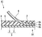
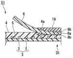
如图1和图2所示,本实施方式的支架1包括线圈3、外部层4、内部层5及挡片(弹性构件)6~11(挡片11未图示),该线圈3是通过使线材2绕轴线C 1进行卷绕而形成的;该外部层4形成为大致管状,且与线圈3同轴地设置在线圈3的外周侧;该内部层5形成为大致管状,且与线圈3同轴地设置在线圈3的内周侧;该挡片(弹性构件)6~11形成为板状且被固定于外部层4的外周面。As shown in Figures 1 and 2, the stent 1 of this embodiment includes a
另外,支架1从设有三个挡片6~8的顶端侧D 1向胆管内插入。In addition, the stent 1 is inserted into the bile duct from the top side D1 provided with three blocking pieces 6-8.
线材2由作为X射线非透射性的材料的钨钢、不锈钢等金属形成,且其剖面形成为圆形。在本实施方式中,例如使用外径为0.11mm的线材2。线圈3形成改变了卷绕线材2的间距的、沿轴线C1方向从顶端侧D1向基端侧D2依次排列并连接普通卷绕线圈14、标记线圈15及普通卷绕线圈16而成的结构。The
标记线圈15通过使线材2绕轴线C1大致紧密卷曲地卷绕而成。另外,在此所说的“大致紧密卷曲”是指以线材2的外径的1倍~7倍的恒定值的间距卷绕线材2。例如,在使用外径为0.11mm的线材2的本实施方式中,在标记线圈15中的相邻的线材2彼此之间设有0.01mm~0.08mm的间隙,线材2的间距P 1为0.12mm~0.19mm。此时,线材2的间距P 1约为线材2的外径的1.1倍~1.7倍。另外,为了便于说明,该间隙在附图中未图示。The
通过如此设置间隙,在形成有标记线圈15的部分,外部层4与内部层5在相邻的线圈2之间的间隙部分相互连接,能够使外部层4与内部层5彼此难以分离。By providing the gap in this way, the
而且,在轴线C 1方向上,标记线圈15的中央部配置为与挡片6~8的基端侧D 2的端部(后述的自由端)对齐。In addition, in the direction of the axis C1, the center portion of the
优选的是,普通卷绕线圈14、16的线材2的间距P2是标记线圈15的线材2的间距P1的2倍~20倍。Preferably, the pitch P2 of the
若线材2的间距之差小于2倍,则在X射线透视下难以分辨标记线圈15与普通卷绕线圈14、16。另外,若间距之差超过20倍,则在弯曲支架1时无法保持内部层5的内腔的大小。If the difference between the pitches of the
外部层4由肖氏硬度为70D以下的聚氨酯树脂(第一树脂材料)形成。外部层4不仅设置在线圈3的外周面,也设置在线材2彼此的间隙中。聚氨酯树脂具有非结晶性,上述肖氏硬度为70D以下的聚氨酯树脂的熔化温度约为100℃~250℃。The
内部层5由属于氟树脂且具有弹性的PFA(全氟烷氧基树脂)、FEP或PTFE(聚四氟乙烯)等形成。The
优选的是,形成为一体的线圈3、外部层4及内部层5具有活体适应性,并且构成为与挡片6~11相比较柔软(反弹性较小)。Preferably, the integrally formed
挡片6~11由与聚氨酯树脂不同的材料、即氟树脂(第二树脂材料。包括PTFE、PFA、PVDF等)形成。PFA的熔化温度为大约380℃。The
如图2中的局部放大图所示,在挡片6的固定于外部层4的固定端(一端)6a侧的外周面实施使用金属钠溶液的公知的化学处理来进行表面改性。在固定端6a侧的外周面形成具有对粘接(连接)有效的官能团的表面处理部6b,并且表面粗糙度(算数平均粗糙度:Ra)变大。As shown in the partial enlarged view of FIG. 2 , the outer peripheral surface of the
在上述化学处理中,通过化学反应使一部分氟分子从氟树脂的碳骨架脱离并在脱离的部分形成对粘接有效的羟基(氢氧基)、羰基等。在该化学处理中,优选使用例如テトラエッチ(日文)(注册商标、润工株式会社制)等。In the above-mentioned chemical treatment, a part of fluorine molecules is detached from the carbon skeleton of the fluororesin by chemical reaction, and a hydroxyl group (hydroxyl group), carbonyl group, etc. effective for adhesion are formed in the detached part. In this chemical treatment, for example, Tetraetchi (Japanese) (registered trademark, manufactured by Junko Co., Ltd.) and the like are preferably used.
同样,在挡片7~11的固定端侧的外周面也形成有表面处理部(在图2的局部放大图中,仅图示了挡片9的固定端9a侧的表面处理部9b)。Similarly, surface treated portions are also formed on the outer peripheral surfaces of the fixed ends of the
挡片6通过使表面处理部6b与外部层4上的顶端侧D1的端部的外周面接触而被固定。而且,挡片6被预先赋予形状等而形成为自由端(另一端)6c沿着轴线C 1向外部层4的中央部侧延伸并向外部层4的径向外侧打开。The
在聚氨酯的熔化温度以上且低于氟树脂的熔化温度的温度下将表面处理部6b与外部层4的外周面相互按压在一起。这样,利用熔化后的外部层4的一部分进入表面处理部6b的较粗的表面内的固着效果、表面处理部6b的羟基或羰基与外部层4的亲和性较高的官能团形成氢键或发生化学反应(化学结合),使表面处理部6b与外部层4的外周面连接。The surface treated
通过在聚氨酯的熔化温度以上且低于氟树脂的熔化温度的温度下将表面处理部6b与外部层4按压在一起,从而防止挡片6发生变形或熔化,通过使外部层4变形来连接表面处理部6b与外部层4。By pressing the
三个挡片6~8配置为绕轴线C 1间隔相等角度、即120°。The three baffles 6-8 are configured to be spaced at equal angles around the axis C1, namely 120°.
与挡片6相同,挡片7、8也将未图示的表面处理部固定在外部层4的顶端侧D 1的端部,并且该挡片7、8形成为自由端沿着轴线C1向外部层4的中央部侧延伸并向外部层4的径向外侧打开。Like the
而且,各个挡片6~8配置为避开其他挡片6~8的隔着轴线C1的相对位置。即,例如,如图3所示,挡片6配置为避开隔着轴线C1的挡片7、8的相对位置T 1、T2。Furthermore, each shutter piece 6-8 is arrange|positioned so that the relative position across the axis C1 of the other shutter piece 6-8 may be avoided. That is, for example, as shown in FIG. 3 , the blocking
如图1和图2所示,与挡片6~8相同,三个挡片9~11也通过使表面处理部与外部层4上的基端侧D 2的端部的外周面接触而被固定。三个挡片9~11形成为,成为固定端的相反侧的端部的自由端沿着轴线C1向外部层4的中央部侧延伸并向外部层4的径向外侧打开。As shown in FIGS. 1 and 2 , like the
挡片9~11的长度方向的长度被设定为比挡片6~8的长度方向的长度短。The length in the longitudinal direction of the flaps 9 to 11 is set to be shorter than the length in the longitudinal direction of the
挡片9~11配置为绕轴线C 1间隔相等角度。在与轴线C1平行地观察时,挡片9~11配置为挡片9与挡片6重叠、挡片10与挡片7重叠以及挡片11与挡片8重叠。The baffles 9-11 are arranged at equal angles around the axis C1. The flaps 9 to 11 are arranged so that the flap 9 overlaps the
如图2和图3所示,在本实施方式中,以覆盖挡片6~8的固定端侧的外周面与外部层4的顶端侧D1的外周面的方式安装有形成为筒状的固定构件19。固定构件19由与外部层4相同的树脂材料形成。As shown in FIGS. 2 and 3 , in this embodiment, a cylindrical fixing member is attached so as to cover the outer peripheral surfaces of the
外部层4的外周面与固定构件19的内周面在聚氨酯树脂的熔化温度以上的温度下熔接。The outer peripheral surface of the
挡片6~8的表面处理部与固定构件19的内周面通过在聚氨酯树脂的熔化温度以上且低于氟树脂的熔化温度的温度下相互按压在一起而借助固着效果与化学结合等连接。The surface treated parts of the
与上述固定构件19相同,以覆盖挡片9~11的固定端侧的外周面与外部层4的基端侧D2的外周面的方式安装有形成为筒状的固定构件20。Similar to the fixing
由于与上述固定构件19相同,固定构件20也被连接于挡片9~11的固定端侧的外周面,并且熔接在外部层4的基端侧D2的外周面,因此省略详细说明。Like the above-mentioned fixing
接着,以下,以将支架1留置在胆管内的方法为例对以上述方式构成的支架1的动作进行说明。Next, the operation of the stent 1 configured as above will be described below by taking a method of indwelling the stent 1 in the bile duct as an example.
首先,使用者将侧视型的内窥镜从嘴等自然开口插入患者的体腔内,如图4所示,使内窥镜E1的顶端前进至十二指肠乳头H1附近。First, the user inserts a side-viewing endoscope into the patient's body cavity through a natural opening such as the mouth, and advances the tip of the endoscope E1 to the vicinity of the duodenal papilla H1 as shown in FIG. 4 .
接着,从内窥镜E1的未图示的钳子口插入引导线E2,一边适当地操作未图示的抬起台,一边使引导线E 2的顶端朝向十二指肠乳头H1突出。Next, the guide wire E2 is inserted from the unshown forceps mouth of the endoscope E1, and the tip of the guide wire E2 is protruded toward the duodenal papilla H1 while appropriately operating the unshown lifting table.
然后,将引导线E2的顶端从十二指肠乳头H1插入到胆管H2内。Then, the tip of the guide wire E2 is inserted from the duodenal papilla H1 into the bile duct H2.
进而,在X射线透视下确认十二指肠乳头H1与胆管H2的狭窄部H3的形状。选择各个挡片6~11打开时的、从挡片6~8的自由端到挡片9~11的自由端的轴线C1方向上的长度达到从十二指肠乳头H1越过胆管H2的狭窄部H3的长度的支架1。Furthermore, the shape of the narrow portion H3 between the duodenal papilla H1 and the bile duct H2 was confirmed under X-ray fluoroscopy. When each blocking piece 6-11 is opened, the length in the direction of the axis C1 from the free end of the blocking piece 6-8 to the free end of the blocking piece 9-11 reaches the narrow part H3 crossing the bile duct H2 from the duodenal papilla H1 The length of the bracket 1.
接着,使用者在X射线透视下一边确认支架1的标记线圈15与胆管H2的位置和形状,一边利用从钳子口插入的未图示的支架输送导管沿着导线E 2将支架1从顶端侧D 1插入胆管H2内。Next, the user confirms the position and shape of the
当支架1的顶端侧D1到达胆管H2的狭窄部H3时,挡片6~8被狭窄部H3朝向轴线C1按压。当支架1进一步向胆管H2内插入且挡片6~8超过狭窄部H 3时,如图5所示,挡片6~8的自由端侧打开,挡片6~8卡定于狭窄部H3。When the distal end side D1 of the stent 1 reaches the narrow portion H3 of the bile duct H2, the
此时,由于选择了以上述方式设定从挡片6~8的自由端到挡片9~11的自由端的轴线C 1方向上的长度的支架1,因此挡片9~11也卡定于十二指肠乳头H1。At this time, since the bracket 1 with the length in the axis C1 direction from the free ends of the blocking
接着,使用者将内窥镜E1和引导线E2从患者的体腔内取出,结束一系列的方法。Next, the user takes out the endoscope E1 and the guide wire E2 from the patient's body cavity, and a series of methods ends.
在支架中,外部层等主体为了追随于活体的管腔的形状、活体的运动而要求容易弯曲,另一方面,挡片为了可靠地卡定于活体而要求一定的硬度。因此,在将挡片熔接于主体的情况下,将硬度差较大的构件彼此熔接。In the stent, the main body such as the outer layer is required to be easy to bend in order to follow the shape of the lumen of the living body and the movement of the living body, while the stopper is required to have a certain hardness in order to be reliably locked to the living body. Therefore, when welding the flap to the main body, members having a large difference in hardness are welded to each other.
当对两个构件进行熔接时,优选的是,在使两个构件分别熔化到一定程度的状态下进行熔接。通常,由于材料硬度越高则熔化温度越高,因此硬度差较大的构件之间的熔化温度之差较大。由于对硬度差较大的构件彼此进行熔接时的温度设定为熔化温度较高一方的构件的熔化温度以上,因此熔化温度较低一方的构件被加热至相对于自身的熔化温度来说相当高的温度,较强地受到热量所带来的影响。When welding two members, it is preferable to perform welding in a state where the two members are respectively melted to a certain extent. Generally, since the harder the material, the higher the melting temperature, the difference in melting temperature between components with a larger difference in hardness is larger. Since the temperature for welding members with a large difference in hardness is set to be higher than the melting temperature of the member with the higher melting temperature, the member with the lower melting temperature is heated to a considerably higher melting temperature. The temperature is strongly affected by the heat.
另外,在将挡片的一部分热熔接于主体的情况下,熔接部附近局部结晶化而变硬。In addition, when a part of the flap is thermally welded to the main body, the vicinity of the welded portion is locally crystallized and hardened.
根据本发明的支架1,挡片6的表面处理部6b与外部层4的外周层在聚氨酯树脂的熔化温度以上且低于氟树脂的熔化温度的温度下相互按压在一起,从而使熔化后的外部层4的一部分与表面处理部6b连接。According to the bracket 1 of the present invention, the surface-treated
因此,防止在将挡片6安装于外部层4时挡片6发生变形或熔化。即使在连接由相互不同的材料形成的外部层4与挡片6时,也防止了挡片6的表面处理部6b结晶化而硬化。当挡片6结晶化而硬化时,存在挡片6在反复变形时从结晶化后的部分的界面断裂的可能性。Therefore, deformation or melting of the
因而,能够使挡片6的表面处理部6b可靠地与外部层4的外周面连接,能够使支架1更长时间地卡定于胆管H2的狭窄部H3。即,能够防止支架1从所留置的胆管内移动而移动至未预想的位置。Therefore, the surface-treated
另外,由于挡片6是相对于外部层4独立的构件,因此能够分别独立地设定挡片6与外部层4的硬度、反弹性等。In addition, since the
由于挡片6由树脂材料中弯曲弹性模量较大的氟树脂形成,因此能够使挡片6可靠地卡定于胆管H2的狭窄部H3。由于氟树脂的表面的摩擦阻力较小,因此能够提高例如向内窥镜的通道内插入支架1时的插入性。Since the
另外,在挡片6的固定端6a侧的外周面,通过实施使用金属钠溶液的化学处理而形成有表面变粗糙的表面处理部6b。因此,当在预定的温度下将表面处理部6b与外部层4的外周面按压在一起时,熔化后的外部层4进入表面处理部6b的粗糙的表面内,从而能够使挡片6的表面处理部6b更可靠地连接于外部层4。在本发明的一个实施方式的化学处理中,并非以在挡片6的固定端6a侧的外周面上重新堆积的方式形成层,而是将炭骨架的氟分子置换为羟基等。因而,能够抑制表面处理部6b与外部层4之间的粘接部分的外径变大。In addition, on the outer peripheral surface of the
由于形成于表面处理部6b的羟基、羰基与外部层4的亲和性较高的官能团形成氢键或发生化学反应,因此能够使挡片6的表面处理部6b更可靠地连接于外部层4。Since the hydroxyl group and carbonyl group formed on the
挡片6~8绕轴线C1间隔相等角度地设有三个,各个挡片配置为避开其他挡片的相对位置。因此,如图3所示,能够将设有挡片6~8的部分的支架1的外径L的尺寸抑制得较小,能够提高将支架1插入支架输送导管、内窥镜等的通道内时的插入性。另外,在支架1的外径恒定的情况下,能够使支架1的内径变大。Three baffles 6-8 are provided at equal angular intervals around the axis C1, and each baffle is configured to avoid the relative positions of other baffles. Therefore, as shown in FIG. 3 , the size of the outer diameter L of the stent 1 at the portion provided with the
由于在挡片6~8的固定端侧的外周面与外部层4的外周面安装有固定构件19,因此能够将挡片6~8的固定端更可靠地固定于外部层4的外周面。Since the fixing
另外,通过以沿轴线C1延伸的方式配置挡片6~8并将其固定端分别安装于外部层4的顶端侧D1的端部,从而能够在安装有该挡片6~8的部分使支架1变硬。因此,能够提高支架1的顶端侧D1的向胆管H2的狭窄部H3的插入性。另外,通过使挡片6~8的固定端固定于外部层4的外周面的位置向轴线C1方向的中央部侧偏移,能够调节支架1的顶端侧D1的牢固度。In addition, by arranging the blocking pieces 6-8 so as to extend along the axis C1 and attaching their fixed ends to the ends of the front end side D1 of the
另外,能够使本实施方式的挡片6变形为以下说明的各种结构。In addition, the
例如,如图6所示的支架31那样,在上述实施方式的支架1中,也可以不具备固定构件19而进一步将挡片6的固定端6a直接连接于内部层5的外周面。通过如此构成,能够将支架31的顶端侧D1的外径尺寸抑制得较小。For example, as in the
如图7所示的支架41那样,在上述变形例的支架31中,也可以将挡片6配置为穿过相邻的线材2之间。通过如此构成,能够起到与上述变形例的支架31相同的效果,并且能够将线材2配置至支架41的顶端侧D 1。能够使支架41在X射线透视下可目视确认的长度变长。另外,在本变形例的支架41中,也可以将挡片6的固定端6a直接连接于线圈3的外表面。As with the
另外,如图8所示的支架51那样,在上述实施方式的支架1中,在外部层4的顶端侧D 1的外周面形成凹部4a。也可以将挡片6的固定端6a连接于该凹部4a,并且利用固定构件19覆盖挡片6的固定端6a。通过如此构成,能够将支架51的顶端侧D1的外径尺寸抑制得较小。In addition, as in the
如图9所示的支架61那样,在上述实施方式的支架1中,也可以不具备固定构件19,使挡片6~8一体化而形成挡片部62。挡片部62具有上述挡片6~8和连接于挡片6~8的固定端的筒状的连接构件63。在本变形例中,挡片6~8与连接构件63利用氟树脂等形成为一体。在连接构件63的内周面形成有未图示的表面处理部,挡片部62的表面处理部与外部层4的外周面通过化学结合而连接。Like the
通过如此构成,即使没有固定构件19也能够将挡片6~8可靠地连接于外部层4的外周面,能够将支架61的顶端侧D1的外径尺寸抑制得较小。With such a configuration, the
以上,参照附图详细说明了本发明的实施方式,但是具体的结构并不限于这些实施方式,也包含不脱离本发明的主旨的范围内的结构的变更等。As mentioned above, although embodiment of this invention was described in detail with reference to drawings, the specific structure is not limited to these embodiment, The change of structure etc. in the range which does not deviate from the summary of this invention is included.
例如,在上述实施方式中,将三个挡片6~8配置为绕轴线C1间隔相等角度。但是,只要各个挡片配置为避开其他挡片的隔着轴线C1的相对位置,设置于支架1的顶端侧D1的挡片的数量也可以是任意的。只是,当设置在顶端侧D1的挡片的数量为奇数时,即使挡片绕轴线C1间隔相等角度地设置,各个挡片也不会配置在与其他挡片的相对位置,因此是更加优选的。For example, in the above-described embodiment, the three
另外,在与轴线C1方向平行地观察时,在六个挡片6~11中,优选的是各个挡片分别配置为避开其他五个挡片的相对位置。通过如此构成挡片6~11,在与轴线C1方向平行地观察时,在支架1的全长中任一位置的径向上都能够将支架1的外径尺寸抑制得较小。In addition, when viewed parallel to the axis C1 direction, among the six
另外,在上述实施方式中,在挡片6~8与外部层4之间的连接强度充足的情况下,在支架1中也可以不具有固定构件19。通过如此构成,能够抑制设有挡片6~8的部分的支架1的外径。In addition, in the above-described embodiment, when the connection strength between the
若在聚氨酯树脂的熔化温度以上且低于氟树脂的熔化温度的温度下将挡片6与外部层4按压在一起,则外部层4发生变形。因而,也可以通过将挡片6与外部层4按压在一起而在外部层4的外周面形成与挡片6的形状对应的凹坑(挡片6被上述狭窄部H3朝向轴线C1按压时的容纳部)。When the
在上述实施方式中,虽利用聚氨酯树脂形成外部层4,但是形成外部层4的材料并不限于此,例如,能够适当使用聚酰氨类弹性体/聚乙烯类弹性体、软质聚乙烯、聚乙烯类弹性体、聚酯类弹性体等。In the above-mentioned embodiment, although the
另外,形成挡片6~11的材料并不限于氟树脂,也能够适当使用聚醚醚酮树脂等。In addition, the material forming the
在上述实施方式中,线圈3虽具有紧密卷曲地卷绕线材2而成的标记线圈15,但是这并不是必需的结构。这是因为,在X射线透视下,只要能够看清线圈3的大致形状就足够了。In the above-described embodiment, the
产业上的可利用性Industrial availability
针对形成于血管、消化管、胆管等活体内管腔的狭窄部,能够适当使用用于使该狭窄部扩张、并维持持续张开状态的医用支架。而且,本发明适合于提供一种利用与外部层不同的材料形成弹性构件、并且通过防止弹性构件与外部层之间的连接部发生硬化而使弹性构件可靠地连接于外部层的医用支架。A medical stent for dilating the stenosis and maintaining the stenosis continuously can be suitably used for a stenosis formed in a lumen of a living body such as a blood vessel, an alimentary canal, and a bile duct. Also, the present invention is suitable for providing a medical stent in which the elastic member is formed using a different material from the outer layer, and the elastic member is reliably connected to the outer layer by preventing hardening of the connecting portion between the elastic member and the outer layer.
附图标记说明Explanation of reference signs
1、31、41、51、61支架(医用支架);3线圈;4外部层;5内部层;6~11挡片(弹性构件);6a、9a 固定端(一端);6b、9b 表面处理部;6c 自由端(另一端);19、20固定构件;C 1轴线。1, 31, 41, 51, 61 stent (medical stent); 3 coil; 4 outer layer; 5 inner layer; 6~11 block (elastic member); 6a, 9a fixed end (one end); 6b, 9b surface treatment Department; 6c free end (the other end); 19, 20 fixed member; C 1 axis.
Claims (5)
Applications Claiming Priority (3)
| Application Number | Priority Date | Filing Date | Title |
|---|---|---|---|
| JP2010244230 | 2010-10-29 | ||
| JP2010-244230 | 2010-10-29 | ||
| PCT/JP2011/074931WO2012057313A1 (en) | 2010-10-29 | 2011-10-28 | Medical stent |
Publications (2)
| Publication Number | Publication Date |
|---|---|
| CN102958472Atrue CN102958472A (en) | 2013-03-06 |
| CN102958472B CN102958472B (en) | 2015-09-09 |
Family
ID=45994016
Family Applications (1)
| Application Number | Title | Priority Date | Filing Date |
|---|---|---|---|
| CN201180029025.9AActiveCN102958472B (en) | 2010-10-29 | 2011-10-28 | Medical rack |
Country Status (5)
| Country | Link |
|---|---|
| US (1) | US8685081B2 (en) |
| EP (1) | EP2564818B1 (en) |
| JP (1) | JP5124703B2 (en) |
| CN (1) | CN102958472B (en) |
| WO (1) | WO2012057313A1 (en) |
Cited By (1)
| Publication number | Priority date | Publication date | Assignee | Title |
|---|---|---|---|---|
| CN110769786A (en)* | 2017-06-13 | 2020-02-07 | 株式会社钟化 | Indwelling tube in organism |
Families Citing this family (3)
| Publication number | Priority date | Publication date | Assignee | Title |
|---|---|---|---|---|
| WO2014136334A1 (en) | 2013-03-07 | 2014-09-12 | オリンパスメディカルシステムズ株式会社 | Medical stent |
| WO2018230434A1 (en)* | 2017-06-13 | 2018-12-20 | 株式会社カネカ | In vivo indwelling tube and method for producing same |
| EP4460266A1 (en)* | 2022-02-04 | 2024-11-13 | Boston Scientific Scimed Inc. | Stent including anti-migration members |
Citations (10)
| Publication number | Priority date | Publication date | Assignee | Title |
|---|---|---|---|---|
| US5282860A (en)* | 1991-10-16 | 1994-02-01 | Olympus Optical Co., Ltd. | Stent tube for medical use |
| US5514176A (en)* | 1995-01-20 | 1996-05-07 | Vance Products Inc. | Pull apart coil stent |
| JP2002355316A (en)* | 2001-03-30 | 2002-12-10 | Terumo Corp | Stent cover and stent |
| US20040098099A1 (en)* | 2002-11-15 | 2004-05-20 | Mccullagh Orla | Braided stent and method for its manufacture |
| JP3619527B2 (en)* | 1991-10-16 | 2005-02-09 | オリンパス株式会社 | In-vivo indwelling tube |
| CN2728439Y (en)* | 2004-09-14 | 2005-09-28 | 浙江大学医学院附属第一医院 | Mushroom-shaped prostate temporary stent tube |
| CN1741772A (en)* | 2002-11-25 | 2006-03-01 | 先进生物假体表面有限公司 | Implantable expandable medical devices having regions of differential mechanical properties and methods of making same |
| US20060173525A1 (en)* | 2005-02-02 | 2006-08-03 | Percutaneous Systems, Inc. | Methods and systems for deploying luminal prostheses |
| JP2008514309A (en)* | 2004-09-28 | 2008-05-08 | コーディス・コーポレイション | Thin film medical devices and delivery systems |
| WO2009145901A1 (en)* | 2008-05-29 | 2009-12-03 | Med Institute, Inc. | Low profile composite endoluminal prostheses |
Family Cites Families (18)
| Publication number | Priority date | Publication date | Assignee | Title |
|---|---|---|---|---|
| US5669930A (en)* | 1994-12-08 | 1997-09-23 | Fuji Systems Corporation | Stent for intracorporeal retention |
| US6124523A (en)* | 1995-03-10 | 2000-09-26 | Impra, Inc. | Encapsulated stent |
| US5957974A (en) | 1997-01-23 | 1999-09-28 | Schneider (Usa) Inc | Stent graft with braided polymeric sleeve |
| JPH11276599A (en)* | 1998-03-27 | 1999-10-12 | Ube Ind Ltd | Stent graft |
| US20080086214A1 (en)* | 1998-08-31 | 2008-04-10 | Wilson-Cook Medical Inc. | Medical device having a sleeve valve with bioactive agent |
| US6544278B1 (en) | 1998-11-06 | 2003-04-08 | Scimed Life Systems, Inc. | Rolling membrane stent delivery system |
| US6325820B1 (en)* | 1998-11-16 | 2001-12-04 | Endotex Interventional Systems, Inc. | Coiled-sheet stent-graft with exo-skeleton |
| JP2001187149A (en)* | 1999-12-28 | 2001-07-10 | Kawasumi Lab Inc | Multilayer clad tube and stent for stent |
| WO2002078573A2 (en) | 2001-03-30 | 2002-10-10 | Terumo Kabushiki Kaisha | Stent cover and stent |
| US20040210300A1 (en)* | 2002-01-19 | 2004-10-21 | Aboul-Hosn Walid Najib | Apparatus and method for maintaining flow through a vessel or duct |
| WO2004049982A2 (en)* | 2002-12-02 | 2004-06-17 | Gi Dynamics, Inc. | Bariatric sleeve |
| US20050137678A1 (en)* | 2003-12-22 | 2005-06-23 | Medtronic Vascular, Inc. | Low profile resorbable stent |
| JP2005278993A (en) | 2004-03-30 | 2005-10-13 | Terumo Corp | Stent for indwelling in living body, and production method of the same |
| JP4901087B2 (en) | 2004-09-24 | 2012-03-21 | オリンパス株式会社 | Stent introduction member, stent delivery catheter, and endoscope treatment system |
| JP2007020635A (en)* | 2005-07-12 | 2007-02-01 | Goodman Co Ltd | Vessel stent |
| US20080051911A1 (en)* | 2006-08-23 | 2008-02-28 | Wilson-Cook Medical Inc. | Stent with antimicrobial drainage lumen surface |
| CA2698096C (en)* | 2007-08-31 | 2013-01-22 | Wilson-Cook Medical Inc. | Medical implant having improved drug eluting features |
| US7998524B2 (en)* | 2007-12-10 | 2011-08-16 | Abbott Cardiovascular Systems Inc. | Methods to improve adhesion of polymer coatings over stents |
- 2011
- 2011-10-28CNCN201180029025.9Apatent/CN102958472B/enactiveActive
- 2011-10-28JPJP2012525551Apatent/JP5124703B2/enactiveActive
- 2011-10-28EPEP11836446.2Apatent/EP2564818B1/ennot_activeNot-in-force
- 2011-10-28WOPCT/JP2011/074931patent/WO2012057313A1/enactiveApplication Filing
- 2012
- 2012-05-30USUS13/483,564patent/US8685081B2/enactiveActive
Patent Citations (10)
| Publication number | Priority date | Publication date | Assignee | Title |
|---|---|---|---|---|
| US5282860A (en)* | 1991-10-16 | 1994-02-01 | Olympus Optical Co., Ltd. | Stent tube for medical use |
| JP3619527B2 (en)* | 1991-10-16 | 2005-02-09 | オリンパス株式会社 | In-vivo indwelling tube |
| US5514176A (en)* | 1995-01-20 | 1996-05-07 | Vance Products Inc. | Pull apart coil stent |
| JP2002355316A (en)* | 2001-03-30 | 2002-12-10 | Terumo Corp | Stent cover and stent |
| US20040098099A1 (en)* | 2002-11-15 | 2004-05-20 | Mccullagh Orla | Braided stent and method for its manufacture |
| CN1741772A (en)* | 2002-11-25 | 2006-03-01 | 先进生物假体表面有限公司 | Implantable expandable medical devices having regions of differential mechanical properties and methods of making same |
| CN2728439Y (en)* | 2004-09-14 | 2005-09-28 | 浙江大学医学院附属第一医院 | Mushroom-shaped prostate temporary stent tube |
| JP2008514309A (en)* | 2004-09-28 | 2008-05-08 | コーディス・コーポレイション | Thin film medical devices and delivery systems |
| US20060173525A1 (en)* | 2005-02-02 | 2006-08-03 | Percutaneous Systems, Inc. | Methods and systems for deploying luminal prostheses |
| WO2009145901A1 (en)* | 2008-05-29 | 2009-12-03 | Med Institute, Inc. | Low profile composite endoluminal prostheses |
Non-Patent Citations (1)
| Title |
|---|
| 周震 等: "《印刷材料》", 30 September 2001* |
Cited By (1)
| Publication number | Priority date | Publication date | Assignee | Title |
|---|---|---|---|---|
| CN110769786A (en)* | 2017-06-13 | 2020-02-07 | 株式会社钟化 | Indwelling tube in organism |
Also Published As
| Publication number | Publication date |
|---|---|
| US20120330433A1 (en) | 2012-12-27 |
| EP2564818A1 (en) | 2013-03-06 |
| US8685081B2 (en) | 2014-04-01 |
| WO2012057313A1 (en) | 2012-05-03 |
| JPWO2012057313A1 (en) | 2014-05-12 |
| CN102958472B (en) | 2015-09-09 |
| JP5124703B2 (en) | 2013-01-23 |
| EP2564818A4 (en) | 2013-03-06 |
| EP2564818B1 (en) | 2015-05-13 |
Similar Documents
| Publication | Publication Date | Title |
|---|---|---|
| US10695531B2 (en) | Balloon catheter and medical elongated body | |
| US8021352B2 (en) | Unfused catheter body feature and methods of manufacture | |
| JP6673821B2 (en) | catheter | |
| JP6592892B2 (en) | Balloon catheter | |
| JP2004357805A (en) | Catheter assembly | |
| JP2015525636A (en) | Expandable guide extension catheter | |
| CN106413794A (en) | Medical devices for accessing body lumens | |
| JP2006288670A (en) | Catheter | |
| JP2022037184A (en) | Medical long body and medical equipment set | |
| CN102958472B (en) | Medical rack | |
| JP2016116815A (en) | Indwelling implement delivery device | |
| JP6897239B2 (en) | catheter | |
| JP2018000372A (en) | Balloon catheter | |
| JP2013192716A (en) | Medical instrument | |
| JP2005211308A (en) | Catheter and manufacturing method thereof | |
| JP7378459B2 (en) | Medical tubular body transport device and its manufacturing method | |
| JP2018187229A (en) | Medical long body | |
| JP2017063828A (en) | Stent delivery system and catheter assembly | |
| JP2008104658A (en) | Medical balloon catheter | |
| EP4335479A1 (en) | Catheter | |
| JP2020124232A (en) | Stent | |
| WO2023176864A1 (en) | Chip used at distal end of medical device to be inserted into body, and medical device | |
| JP2024140078A (en) | Tip for use at the distal end of a medical tubular body delivery device, and medical tubular body delivery device | |
| JP5619509B2 (en) | Stent delivery system and balloon catheter | |
| JP2008104660A (en) | Medical balloon catheter |
Legal Events
| Date | Code | Title | Description |
|---|---|---|---|
| C06 | Publication | ||
| PB01 | Publication | ||
| C10 | Entry into substantive examination | ||
| SE01 | Entry into force of request for substantive examination | ||
| C14 | Grant of patent or utility model | ||
| GR01 | Patent grant | ||
| C41 | Transfer of patent application or patent right or utility model | ||
| TR01 | Transfer of patent right | Effective date of registration:20151112 Address after:Tokyo, Japan, Japan Patentee after:Olympus Corporation Address before:Tokyo, Japan, Japan Patentee before:Olympus Medical Systems Corp. |