CN102957085A - Optical device for laser beam wave-front correction and wave-front correction method - Google Patents
Optical device for laser beam wave-front correction and wave-front correction methodDownload PDFInfo
- Publication number
- CN102957085A CN102957085ACN2012104686158ACN201210468615ACN102957085ACN 102957085 ACN102957085 ACN 102957085ACN 2012104686158 ACN2012104686158 ACN 2012104686158ACN 201210468615 ACN201210468615 ACN 201210468615ACN 102957085 ACN102957085 ACN 102957085A
- Authority
- CN
- China
- Prior art keywords
- temperature
- optical material
- conditioning unit
- laser beam
- temperature conditioning
- Prior art date
- Legal status (The legal status is an assumption and is not a legal conclusion. Google has not performed a legal analysis and makes no representation as to the accuracy of the status listed.)
- Pending
Links
Images


Landscapes
- Laser Beam Processing (AREA)
- Optical Modulation, Optical Deflection, Nonlinear Optics, Optical Demodulation, Optical Logic Elements (AREA)
Abstract
Description
Translated fromChinese技术领域technical field
本发明涉及激光技术领域,特别是涉及一种用于激光光束波前校正的光学装置及激光光束波前校正方法。The invention relates to the field of laser technology, in particular to an optical device for correcting the wavefront of a laser beam and a method for correcting the wavefront of the laser beam.
背景技术Background technique
目前,在高功率固体激光器研制中,除了需要提升功率/能量外,还必须研究光束控制与提高光束质量的问题,具有高功率高光束质量的激光才能满足实际应用的需要。在实际工作中,高功率激光系统输出的激光都有振幅调制和相位畸变,理论和实验研究都证明,对于远场光束质量来说,相位畸变是主要影响因素。激光束通过具有一定温度分布的激光增益介质或非理想的光学系统后,其波前会发生畸变,这种波前畸变通常会随着激光输出功率的增加而变得更加严重。At present, in the development of high-power solid-state lasers, in addition to the need to increase power/energy, it is also necessary to study beam control and improve beam quality. Lasers with high power and high beam quality can meet the needs of practical applications. In actual work, the laser output by a high-power laser system has amplitude modulation and phase distortion. Both theoretical and experimental studies have proved that phase distortion is the main influencing factor for the quality of far-field beams. After the laser beam passes through a laser gain medium with a certain temperature distribution or a non-ideal optical system, its wavefront will be distorted, and this wavefront distortion will usually become more serious as the laser output power increases.
高功率激光束波前的畸变中一般包含热透镜效应等因素引起的低阶畸变和温度不均匀分布、衍射等因素引起的高阶畸变,低阶畸变可以利用光学元件进行修正或补偿,高阶畸变目前基本采用主要由变形镜组成的自适应光学系统进行校正,这项技术通常用来校正大气扰动引起的相差,用于高功率固体激光系统中也获得了成功。但是随高功率固体激光技术的发展,激光器的输出功率越来越高,影响的波前畸变也越来越大,变形镜系统遇到了一些难以逾越的障碍,一是破坏问题,变形镜要通过镜面起伏变形来改变激光的波前,所以镜面膜层较薄,且散热能力较差,因此抗激光损伤能力相对较弱,在高功率激光系统中经常发生变形镜表面损伤问题。二是行程量小,受变形镜材料限制,变形镜面形不能在大范围内变化,通常的最大行程在10μm左右,而高功率固体激光系统中如果要提高激光输出功率激光光束就要通过更长的增益介质,相应的会产生很大的波前畸变,这就经常会超出变形镜的行程范围,因此反过来制约了激光功率的进一步提高。The wavefront distortion of high-power laser beam generally includes low-order distortion caused by factors such as thermal lens effect and high-order distortion caused by factors such as uneven temperature distribution and diffraction. Low-order distortion can be corrected or compensated by optical elements, and high-order Distortion is currently basically corrected by an adaptive optics system mainly composed of deformable mirrors. This technology is usually used to correct the phase difference caused by atmospheric disturbances, and it has also been successfully used in high-power solid-state laser systems. However, with the development of high-power solid-state laser technology, the output power of lasers is getting higher and higher, and the wavefront distortion affected is also increasing. The deformable mirror system has encountered some insurmountable obstacles. One is the problem of damage. The mirror surface fluctuates and deforms to change the wavefront of the laser, so the mirror film layer is thin and the heat dissipation ability is poor, so the ability to resist laser damage is relatively weak, and the surface damage of the deformed mirror often occurs in high-power laser systems. The second is the small amount of stroke. Limited by the material of the deformable mirror, the shape of the deformable mirror cannot be changed in a wide range. The usual maximum stroke is about 10 μm. In a high-power solid-state laser system, if the laser output power is to be increased, the laser beam must pass through a longer distance. The corresponding gain medium will produce a large wavefront distortion, which often exceeds the travel range of the deformable mirror, which in turn restricts the further improvement of the laser power.
除了以变形镜为代表的反射式波前校正器之外,还有透射式的波前校正器,其中主要有衍射光学元件和透射式液晶空间光调制器。衍射光学元件利用了光的波动性,在一片光学材料的基底上做出许多台阶状的亚微米、微米量级的微结构,当光投射到这些带有浮雕结构的器件表面时,波前受到调制,进而实现某些光学功能。主要优点是这种元件是纯相位型的,有极高的衍射效率,不仅能够产生任何形式的波前,而且还能对光波波前进行变换和矫正;可以大量复制;实现系统轻型化、集成化。但其用于高功率激光光束校正时需要准确测量出激光束波前然后再进行光学加工,这就使得其要求激光束有非常好的稳定性和重复性,否则波前校正能力大幅度降低,由于实际工作中高功率固体激光器的调试和元器件更换等改变是不可避免的,所以激光波前难以保持不变,所以这种方法目前很少用于高功率固体激光光束波前的校正。In addition to reflective wavefront correctors represented by deformable mirrors, there are also transmissive wavefront correctors, including diffractive optical elements and transmissive liquid crystal spatial light modulators. Diffractive optical elements make use of the wave nature of light to make many step-like submicron and micron-scale microstructures on a piece of optical material substrate. When the light is projected onto the surface of these devices with relief structures, the wavefront is Modulation, and then achieve some optical functions. The main advantage is that this kind of element is pure phase type and has extremely high diffraction efficiency. It can not only generate any form of wavefront, but also transform and correct the wavefront of light waves; it can be copied in large numbers; it can realize light weight and integration of the system change. However, when it is used for high-power laser beam correction, it is necessary to accurately measure the wavefront of the laser beam and then perform optical processing, which requires the laser beam to have very good stability and repeatability, otherwise the wavefront correction capability will be greatly reduced. Since changes such as debugging and component replacement of high-power solid-state lasers are inevitable in actual work, it is difficult to keep the laser wavefront unchanged, so this method is rarely used for wavefront correction of high-power solid-state laser beams.
液晶光调制器是以电写入液晶空间光调制器为核心,结合滤波、CCD采集、监视器及计算机组成的实时、可调控的激光光束空间整形系统。它由两偏振片夹一液晶显示层构成,通过液晶分子的旋光偏振性和双折射性来实现对入射光束的波面振幅和相位的调制,即其光学调制特性主要是旋光偏振性和双折射性。通过设置不同的偏振片的相对偏振方位,改变加在液晶像素上的电压,可获得相应液晶空间光调制器的调制模式与调制特性曲线。现在最通行的电寻址液晶空间光调制器是薄膜晶体管透射阵列式液晶电视,这种电寻址液晶空间光调制器能方便地与计算机接口,在设定的光学调制模式下,实现相应的单元像素的振幅或相位的调制。其优点是实时可控的校正波前,缺点是激光损伤阈值较低,仅适用于高功率激光系统前级,但由于高功率激光系统波前畸变主要产生于放大级,如果采用预控制技术的话有会遇到孔径限制等难题,所以液晶空间光调制器目前也较少用于高功率激光系统中。The liquid crystal light modulator is a real-time and adjustable laser beam space shaping system composed of an electronically written liquid crystal spatial light modulator as the core, combined with filtering, CCD acquisition, monitor and computer. It is composed of two polarizers sandwiching a liquid crystal display layer. The modulation of the wavefront amplitude and phase of the incident beam is realized through the optical polarization and birefringence of liquid crystal molecules, that is, its optical modulation characteristics are mainly optical polarization and birefringence. . By setting the relative polarization orientations of different polarizers and changing the voltage applied to the liquid crystal pixel, the modulation mode and modulation characteristic curve of the corresponding liquid crystal spatial light modulator can be obtained. Now the most popular electrical addressing liquid crystal spatial light modulator is thin film transistor transmission array LCD TV, this electrical addressing liquid crystal spatial light modulator can be easily interfaced with the computer, in the set optical modulation mode, to achieve the corresponding Modulation of the amplitude or phase of a unit pixel. Its advantage is real-time controllable correction of the wavefront. The disadvantage is that the laser damage threshold is low, and it is only suitable for the pre-stage of high-power laser systems. However, since the wavefront distortion of high-power laser systems is mainly generated in the amplification stage, if the pre-control technology is used There may be difficulties such as aperture limitation, so liquid crystal spatial light modulators are currently less used in high-power laser systems.
发明内容Contents of the invention
本发明提供一种用于激光光束波前校正的光学装置及激光光束波前校正方法,以解决现有技术中的上述问题。The present invention provides an optical device for laser beam wavefront correction and a laser beam wavefront correction method to solve the above-mentioned problems in the prior art.
本发明提供一种用于激光光束波前校正的光学装置,包括:设置于固体激光器的激光增益介质之后,光学装置具体包括:光学材料、与光学材料表面相连接的一个或多个温控单元、与各个温控单元相连接的散热装置、以及控制温控单元的温度控制器;光学材料,用于通过一个端面接收从激光增益介质射出的激光光束,并从另一个端面射出激光光束,或者,从接收激光光束的端面射出;温控单元,用于在温度控制器的控制下发热或者制冷;散热装置,用于在温度控制器控制温控单元制冷时,为温控单元排出其产生的废热;温度控制器,用于控制一个或多个温控单元进行发热或者制冷,并控制一个或多个温控单元的发热量或者制冷量,以控制激光光束在光学材料中通过路径上的温度,对射入光学材料的激光光束波前进行矫正。The present invention provides an optical device for laser beam wavefront correction, including: arranged behind the laser gain medium of the solid-state laser, the optical device specifically includes: optical material, one or more temperature control units connected to the surface of the optical material , a heat dissipation device connected to each temperature control unit, and a temperature controller for controlling the temperature control unit; an optical material for receiving the laser beam emitted from the laser gain medium through one end face and emitting the laser beam from the other end face, or , emitted from the end face receiving the laser beam; the temperature control unit is used to heat or cool under the control of the temperature controller; the heat sink is used to discharge the temperature generated by the temperature control unit when the temperature controller controls the cooling Waste heat; temperature controller, used to control one or more temperature control units to generate heat or cool, and to control the heat generation or cooling capacity of one or more temperature control units to control the temperature of the laser beam passing through the optical material , to correct the wavefront of the laser beam entering the optical material.
优选地,光学材料为光学玻璃、陶瓷、或者晶体;光学材料为多边形立体结构;光学材料的两个端面上镀有膜。Preferably, the optical material is optical glass, ceramics, or crystal; the optical material is a polygonal three-dimensional structure; the two ends of the optical material are coated with films.
优选地,温控单元通过导热胶粘接在光学材料的一个或多个面上,或者,温控单元通过金属焊接的方式固定在光学材料的一个或多个面上。Preferably, the temperature control unit is bonded to one or more surfaces of the optical material by thermally conductive glue, or the temperature control unit is fixed to one or more surfaces of the optical material by metal welding.
优选地,在光学材料连接温控单元的表面通过掩膜板被金属化形成由多个金属块组成的金属网格,通过掩膜板被金属化的各个温控单元分别与金属网格中的各个金属块焊接连接,其中,金属网格中的各个金属块之间不互相连接。Preferably, the surface of the optical material connected to the temperature control unit is metallized through a mask plate to form a metal grid composed of a plurality of metal blocks, and each temperature control unit metallized through the mask plate is respectively connected to the metal grid. Each metal block is connected by welding, wherein each metal block in the metal grid is not connected to each other.
优选地,光学材料与每个温控单元之间均设置有一个导热金属锥体,温控单元固定于导热金属锥体的面积较大的一端,导热金属锥体的面积较小一端与光学材料连接,导热金属锥体用于将温控单元的温度传导到光学材料上。Preferably, a heat-conducting metal cone is arranged between the optical material and each temperature control unit, the temperature control unit is fixed on the larger end of the heat-conducting metal cone, and the smaller end of the heat-conducting metal cone is connected to the optical material Connection, the thermally conductive metal cone is used to conduct the temperature of the temperature control unit to the optical material.
优选地,每个温控单元上设置有一个温度传感器,温度传感器用于向温度控制器发送相应温控单元的温度。Preferably, each temperature control unit is provided with a temperature sensor, and the temperature sensor is used to send the temperature of the corresponding temperature control unit to the temperature controller.
优选地,温度控制器具体用于:通过控制激光光束在光学材料中通过路径上的温度,使光学材料中激光光束通过路径上的温差分布与激光增益介质中激光光束通过路径上的的温差分布互补,从而对射入光学材料的激光光束波前进行矫正。Preferably, the temperature controller is specifically used for: by controlling the temperature of the laser beam on the passing path in the optical material, the temperature difference distribution on the passing path of the laser beam in the optical material and the temperature difference distribution on the passing path of the laser beam in the laser gain medium Complementary, so as to correct the wavefront of the laser beam entering the optical material.
优选地,温度控制器具体用于:通过控制激光光束在光学材料中通过路径上的温度,使激光光束通过路径上的光程差积分与激光增益介质的光程差积分相加为零,对射入光学材料的激光光束波前进行矫正。Preferably, the temperature controller is specifically used for: by controlling the temperature of the laser beam passing through the path in the optical material, the sum of the integral of the optical path difference on the passing path of the laser beam and the integral of the optical path difference of the laser gain medium is zero, for The wavefront of the laser beam injected into the optical material is corrected.
优选地,温度控制器具体用于:分别对每一个温控单元进行控制、和/或对由多个温控单元组成的温控单元组进行控制。Preferably, the temperature controller is specifically used for: controlling each temperature control unit respectively, and/or controlling a temperature control unit group composed of a plurality of temperature control units.
优选地,温控单元为温度电子控制器TEC。Preferably, the temperature control unit is a temperature electronic controller TEC.
优选地,温度控制器具体用于:通过控制流过温控单元的电流方向,控制温控单元进行发热或者制冷,并通过控制流过温控单元的电流大小,控制温控单元的发热量或者制冷量,其中,在流过温控单元的电流方向为正向时温控单元制冷,在流过温控单元的电流方向为反向时温控单元发热。Preferably, the temperature controller is specifically used to control the heating or cooling of the temperature control unit by controlling the direction of the current flowing through the temperature control unit, and to control the heating or cooling of the temperature control unit by controlling the magnitude of the current flowing through the temperature control unit. Cooling capacity, wherein, when the direction of current flowing through the temperature control unit is positive, the temperature control unit cools down, and when the direction of current flowing through the temperature control unit is reverse, the temperature control unit generates heat.
本发明还提供了一种激光光束波前校正方法,包括:光学材料的一个端面接收从激光增益介质射出的激光光束;温度控制器控制光学材料的温度分布,从而控制激光光束在光学材料中通过路径上的温度,对射入光学材料的激光光束波前进行矫正;进行波前矫正后的激光光束从光学材料的另一个端面射出,或者,从接收激光光束的端面射出。The present invention also provides a laser beam wavefront correction method, comprising: one end face of the optical material receives the laser beam emitted from the laser gain medium; the temperature controller controls the temperature distribution of the optical material, thereby controlling the laser beam to pass through the optical material The temperature on the path corrects the wavefront of the laser beam entering the optical material; the laser beam after wavefront correction is emitted from the other end face of the optical material, or from the end face receiving the laser beam.
优选地,温度控制器控制光学材料的温度分布具体包括:温度控制器控制固定于光学材料表面的一个或多个温控单元进行发热或者制冷、并控制一个或多个温控单元的发热量或者制冷量,从而控制光学材料的温度分布。Preferably, the temperature controller controlling the temperature distribution of the optical material specifically includes: the temperature controller controls one or more temperature control units fixed on the surface of the optical material to generate heat or cool down, and controls the heat generation or cooling of the one or more temperature control units. Cooling capacity, thereby controlling the temperature distribution of optical materials.
优选地,温度控制器控制光学材料中通过路径上的温差分布与激光增益介质的温差分布互补。Preferably, the temperature controller controls the temperature difference distribution on the passing path in the optical material to complement the temperature difference distribution of the laser gain medium.
优选地,温度控制器控制光学材料中通过路径上的温差分布与激光增益介质的温差分布互补具体包括:温度控制器控制光学材料的温度分布,使得激光光束通过路径上的光程差积分与激光增益介质的光程差积分相加为零。Preferably, the temperature controller controls the temperature difference distribution on the passing path of the optical material to be complementary to the temperature difference distribution of the laser gain medium, specifically comprising: the temperature controller controls the temperature distribution of the optical material so that the integration of the optical path difference on the passing path of the laser beam and the laser beam The integrals of the optical path differences of the gain media add to zero.
优选地,温控单元为温度电子控制器TEC;温度控制器控制固定于光学材料表面的一个或多个温控单元进行发热或者制冷、并控制一个或多个温控单元的发热量或者制冷量具体包括:温度控制器通过控制流过温控单元的电流方向,控制温控单元进行发热或者制冷,并通过控制流过温控单元的电流大小,控制温控单元的发热量或者制冷量,其中,在流过温控单元的电流方向为正向时温控单元制冷,在流过温控单元的电流方向为反向时温控单元发热。Preferably, the temperature control unit is a temperature electronic controller TEC; the temperature controller controls one or more temperature control units fixed on the surface of the optical material to generate heat or cool down, and controls the heat generation or cooling capacity of one or more temperature control units Specifically, the temperature controller controls the temperature control unit to generate heat or cool by controlling the direction of the current flowing through the temperature control unit, and controls the heating or cooling capacity of the temperature control unit by controlling the current flowing through the temperature control unit. , when the direction of current flowing through the temperature control unit is positive, the temperature control unit cools down, and when the direction of current flowing through the temperature control unit is reverse, the temperature control unit generates heat.
本发明有益效果如下:The beneficial effects of the present invention are as follows:
通过在固体激光器的激光增益介质后增加本发明实施例的光学材料,利用温度控制技术控制光学材料中的温度分布,由于光学材料的折射率随温度变化的特性,当激光束通过该光学材料后,由于波面上不同点之间存在光程差,因此实现了对波前的控制,本发明实施例的技术方案的光学材料抗激光损伤阈值非常高,此外,可以采用激光透射率很高的光学材料,所以对激光吸收很少;本发明实施例的光学材料造价低,对光学材料生产和加工没有严苛的要求,温度控制器件也是市场化程度很高的器件;此外,本发明实施例的波前校正动态范围大,很简单的增加光学材料长度就可以增加激光光束在波前校正器中的传播距离,进而增加光程差,也就是增加了波前校正动态范围。By adding the optical material of the embodiment of the present invention behind the laser gain medium of the solid-state laser, using temperature control technology to control the temperature distribution in the optical material, due to the characteristic that the refractive index of the optical material changes with temperature, when the laser beam passes through the optical material , because there is an optical path difference between different points on the wave surface, the control of the wave front is realized. The optical material anti-laser damage threshold of the technical solution of the embodiment of the present invention is very high. In addition, an optical material with a high laser transmittance can be used. material, so it has little absorption of laser light; the cost of the optical material of the embodiment of the present invention is low, there are no strict requirements on the production and processing of the optical material, and the temperature control device is also a device with a high degree of marketability; in addition, the embodiment of the present invention The dynamic range of wavefront correction is large, and simply increasing the length of the optical material can increase the propagation distance of the laser beam in the wavefront corrector, thereby increasing the optical path difference, that is, increasing the dynamic range of wavefront correction.
上述说明仅是本发明技术方案的概述,为了能够更清楚了解本发明的技术手段,而可依照说明书的内容予以实施,并且为了让本发明的上述和其它目的、特征和优点能够更明显易懂,以下特举本发明的具体实施方式。The above description is only an overview of the technical solution of the present invention. In order to better understand the technical means of the present invention, it can be implemented according to the contents of the description, and in order to make the above and other purposes, features and advantages of the present invention more obvious and understandable , the specific embodiments of the present invention are enumerated below.
附图说明Description of drawings
通过阅读下文优选实施方式的详细描述,各种其他的优点和益处对于本领域普通技术人员将变得清楚明了。附图仅用于示出优选实施方式的目的,而并不认为是对本发明的限制。而且在整个附图中,用相同的参考符号表示相同的部件。在附图中:Various other advantages and benefits will become apparent to those of ordinary skill in the art upon reading the following detailed description of the preferred embodiment. The drawings are only for the purpose of illustrating a preferred embodiment and are not to be considered as limiting the invention. Also throughout the drawings, the same reference numerals are used to designate the same parts. In the attached picture:
图1是本发明实施例的用于激光光束波前校正的光学装置的结构示意图;FIG. 1 is a schematic structural view of an optical device for laser beam wavefront correction according to an embodiment of the present invention;
图2是本发明实施例的透射型温度分布式波前控制器的结构示意图一;Fig. 2 is a structural schematic diagram 1 of a transmission type temperature distributed wavefront controller according to an embodiment of the present invention;
图3是本发明实施例的透射型温度分布式波前控制器的结构示意图二;Fig. 3 is a structural schematic diagram II of a transmission type temperature distributed wavefront controller according to an embodiment of the present invention;
图4是本发明实施例的反射型温度分布式波前控制器结构示意图;Fig. 4 is a structural schematic diagram of a reflective temperature distributed wave front controller according to an embodiment of the present invention;
图5是本发明实施例的激光光束波前校正方法的流程图。FIG. 5 is a flow chart of a laser beam wavefront correction method according to an embodiment of the present invention.
具体实施方式Detailed ways
下面将参照附图更详细地描述本公开的示例性实施例。虽然附图中显示了本公开的示例性实施例,然而应当理解,可以以各种形式实现本公开而不应被这里阐述的实施例所限制。相反,提供这些实施例是为了能够更透彻地理解本公开,并且能够将本公开的范围完整的传达给本领域的技术人员。Exemplary embodiments of the present disclosure will be described in more detail below with reference to the accompanying drawings. Although exemplary embodiments of the present disclosure are shown in the drawings, it should be understood that the present disclosure may be embodied in various forms and should not be limited by the embodiments set forth herein. Rather, these embodiments are provided for more thorough understanding of the present disclosure and to fully convey the scope of the present disclosure to those skilled in the art.
本发明提供了一种用于激光光束波前校正的光学装置及激光光束波前校正方法,将阵列热源加载在光学材料表面,当温度平衡后就会在光学材料内部形成各种温场分布,当激光光束通过这个光学材料时其波前就会产生变化,控制这种变化就可以达到改善激光光束波前的目的。在本发明实施例中,可以将一定数量TEC排列起来构成热源阵列,利用TEC兼具制冷和加热的能力,控制每一个TEC单元的温度,最后在光学材料内部形成所需的温度场分布。The invention provides an optical device and a laser beam wavefront correction method for laser beam wavefront correction. The array heat source is loaded on the surface of the optical material, and various temperature field distributions will be formed inside the optical material after the temperature is balanced. When the laser beam passes through this optical material, its wavefront will change, and controlling this change can achieve the purpose of improving the wavefront of the laser beam. In the embodiment of the present invention, a certain number of TECs can be arranged to form a heat source array, and the temperature of each TEC unit can be controlled by using the TECs with both cooling and heating capabilities, and finally form the required temperature field distribution inside the optical material.
以下结合附图以及实施例,对本发明进行进一步详细说明。应当理解,此处所描述的具体实施例仅仅用以解释本发明,并不限定本发明。The present invention will be described in further detail below in conjunction with the accompanying drawings and embodiments. It should be understood that the specific embodiments described here are only used to explain the present invention, not to limit the present invention.
装置实施例Device embodiment
根据本发明的实施例,提供了一种用于激光光束波前校正的光学装置,设置于固体激光器的激光增益介质之后,图1是本发明实施例的用于激光光束波前校正的光学装置的结构示意图,如图1所示,根据本发明实施例的光学装置具体包括:光学材料10、与所述光学材料10表面相连接的一个或多个温控单元12、与各个温控单元12相连接的散热装置14、以及控制所述温控单元12的温度控制器16;以下对本发明实施例的各个模块进行详细的说明。According to an embodiment of the present invention, an optical device for laser beam wavefront correction is provided, which is arranged behind the laser gain medium of a solid-state laser. Figure 1 is an optical device for laser beam wavefront correction according to an embodiment of the present invention As shown in FIG. 1 , the optical device according to the embodiment of the present invention specifically includes: an
光学材料10,用于通过一个端面接收从激光增益介质射出的激光光束,并从另一个端面射出激光光束,或者,从接收激光光束的端面射出;优选地,光学材料10为光学玻璃、陶瓷、或者晶体;光学材料10为多边形立体结构;光学材料10的两个端面上镀有膜。The
温控单元12,用于在温度控制器16的控制下发热或者制冷;优选地,温控单元12通过导热胶粘接在光学材料10的一个或多个面上,或者,温控单元12通过金属焊接的方式固定在光学材料10的一个或多个面上。温控单元12可以为温度电子控制器TEC。The
在实际应用中,可以在光学材料10连接温控单元12的表面通过掩膜板被金属化形成由多个金属块组成的金属网格,通过掩膜板被金属化的各个温控单元12分别与金属网格中的各个金属块焊接连接,其中,金属网格中的各个金属块之间不互相连接。In practical applications, the surface of the
如果需要减少光学材料10的受热面积,光学材料10与每个温控单元12之间均设置有一个导热金属锥体,温控单元12固定于导热金属锥体的面积较大的一端,导热金属锥体的面积较小一端与光学材料10连接,导热金属锥体用于将温控单元12的温度传导到光学材料10上If it is necessary to reduce the heated area of the
为了使温度控制器16准确地控制每一个温控单元12,每个温控单元12上可以设置有一个温度传感器,温度传感器用于向温度控制器16发送相应温控单元12的温度。In order for the
散热装置14,用于在温度控制器16控制温控单元12制冷时,为温控单元12排出其产生的废热;The
温度控制器16,用于控制一个或多个温控单元12进行发热或者制冷,并控制一个或多个温控单元12的发热量或者制冷量,以控制激光光束在光学材料10中通过路径上的温度,对射入光学材料10的激光光束波前进行矫正。The
温度控制器16具体用于:通过控制激光光束在光学材料10中通过路径上的温度,使光学材料10中激光光束通过路径上的温差分布与激光增益介质中激光光束通过路径上的的温差分布互补,从而对射入光学材料10的激光光束波前进行矫正。The
此外,温度控制器16通过控制激光光束在光学材料10中通过路径上的温度,使激光光束通过路径上的光程差积分与所述激光增益介质的光程差积分相加为零,对射入光学材料10的激光光束波前进行矫正。In addition, the
在实际应用中,温度控制器16可以分别对每一个温控单元12进行控制、和/或对由多个温控单元12组成的温控单元12组进行控制。In practical applications, the
在本发明实施例中,如果温控单元12为温度电子控制器TEC,则温度控制器16通过控制流过温控单元12的电流方向,控制温控单元12进行发热或者制冷,并通过控制流过温控单元12的电流大小,控制温控单元12的发热量或者制冷量,其中,在流过温控单元12的电流方向为正向时温控单元12制冷,在流过温控单元12的电流方向为反向时温控单元12发热。In the embodiment of the present invention, if the
以下结合附图,以TEC为例,对本发明实施例的技术方案进行详细说明。The technical solutions of the embodiments of the present invention will be described in detail below with reference to the accompanying drawings and by taking the TEC as an example.
激光增益介质中的温度不均匀分布是导致固体激光光束畸变的主要原因,而固体激光器研制过程中,通过合理设计,通常可以保证激光增益介质吸收的泵浦光均匀,也就是激光增益介质受热近似均匀,温度的不均匀分布主要是由于增益介质的不均匀冷却造成的,而增益介质的冷却都是通过增益介质的外表面进行冷却,与金属散热材料接触良好的地方,激光增益介质的温度较低,反之温度就较高,对于液体冷却方式而言,同样的如果液体流速不均匀或流动方式不同同样会造成激光增益介质的各个部分温度产生差异。对于激光增益介质来说,温度不同时激光增益介质的材料折射率不同,当激光光束通过激光增益介质后对于激光波面来说,所经过的区域光程差不同,因此波面产生变形。根据光的可逆原理,如果主动将通过增益介质后的激光光束再通过一块温度分布与增益介质互补的光学材料,激光光束波前就会得到恢复,再由光程差的累加原理,该补偿光学材料不必处处温度分布与增益介质互补,仅需要保证通过路径上的温度积分也就是光程与增益介质的温度积分相等即可。The uneven temperature distribution in the laser gain medium is the main reason for the distortion of the solid-state laser beam. In the development process of the solid-state laser, through reasonable design, it is usually possible to ensure that the pump light absorbed by the laser gain medium is uniform, that is, the laser gain medium is heated approximately Uniform, uneven temperature distribution is mainly caused by the uneven cooling of the gain medium, and the cooling of the gain medium is done through the outer surface of the gain medium, and the temperature of the laser gain medium is relatively high in the place where it is in good contact with the metal heat dissipation material. Low, otherwise the temperature is high. For liquid cooling, if the liquid flow rate is not uniform or the flow method is different, the temperature of each part of the laser gain medium will also be different. For the laser gain medium, the refractive index of the material of the laser gain medium is different when the temperature is different. When the laser beam passes through the laser gain medium, the optical path difference of the area passed by the laser wavefront is different, so the wavefront is deformed. According to the reversible principle of light, if the laser beam passing through the gain medium is actively passed through an optical material whose temperature distribution is complementary to that of the gain medium, the wavefront of the laser beam will be restored, and then by the accumulation principle of the optical path difference, the compensation optics The temperature distribution of the material does not need to be complementary to that of the gain medium everywhere, and it is only necessary to ensure that the temperature integral on the passing path, that is, the temperature integral of the optical path and the gain medium is equal.
在实际应用中,最好选取对激光透过率高的光学材料,不同激光波长应选用不同透过率波段的光学材料,如1064nm激光可以选用石英玻璃、k9玻璃、Nd:YAG晶体或陶瓷等,将光学材料加工成各种立体结构,以长方体为例,可以将光学材料的两个表面抛光镀膜,作为激光光束的入射面和出射面,激光在长方体的一端进入,在另一个端面输出,在两个侧面排布TEC阵列,对应需校正的波前畸变类型不同,阵列中包含TEC数量可以是一个或几十个。In practical applications, it is best to choose optical materials with high laser transmittance. Optical materials with different transmittance bands should be selected for different laser wavelengths. For example, quartz glass, k9 glass, Nd:YAG crystal or ceramics can be used for 1064nm laser. , to process the optical material into various three-dimensional structures. Taking a cuboid as an example, the two surfaces of the optical material can be polished and coated as the incident surface and the outgoing surface of the laser beam. The laser enters at one end of the cuboid and outputs at the other end. TEC arrays are arranged on two sides, depending on the type of wavefront distortion to be corrected, and the number of TECs included in the array can be one or dozens.
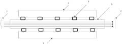
图2是本发明实施例的透射型温度分布式波前控制器的结构示意图一,图3是本发明实施例的透射型温度分布式波前控制器的结构示意图二,如图2和图3所示,1表示入射激光波前,2表示出射激光波前,3表示TEC热沉,4表示TEC单元,5表示光学材料。在图2中,光学材料的上下面固定有TEC单元,在图3中,光学材料的前后面固定有TEC单元,在实际应用中,TEC单元的排列可以有多种结构。如图2、3所示的结构,激光光束1由控制器一端进入波前控制器,通过分析出射激光光束2的波前情况调整各个TEC单元的温度,最后获得改善的激光光束波前。Fig. 2 is a structural schematic diagram 1 of a transmission type temperature distributed wave front controller according to an embodiment of the present invention, and Fig. 3 is a structural schematic diagram 2 of a transmission type temperature distributed wave front controller according to an embodiment of the present invention, as shown in Fig. 2 and Fig. 3 As shown, 1 represents the incident laser wavefront, 2 represents the outgoing laser wavefront, 3 represents the TEC heat sink, 4 represents the TEC unit, and 5 represents the optical material. In Fig. 2, TEC units are fixed on the upper and lower sides of the optical material. In Fig. 3, TEC units are fixed on the front and back of the optical material. In practical applications, the arrangement of TEC units can have various structures. In the structure shown in Figure 2 and 3, the
图4是本发明实施例的反射型温度分布式波前控制器结构示意图,如图4所示,1表示入射激光波前,2表示出射激光波前,3表示TEC热沉,4表示TEC单元,5表示光学材料。在图4中,TEC单元被设置在与激光入射端面相对的端面上,激光光束以0°~90°入射进入光学材料,通过特定温度分布的区域后反射输出,这种方法可以实现光路原路返回,其在激光器中的使用方法就与变形镜类似,通过将光学材料加工成多边形立体结构,可以实现多反射面,根据控制方法不同,TEC等温控单元可以加载在任意一个表面。Fig. 4 is a schematic structural diagram of a reflective temperature distributed wavefront controller according to an embodiment of the present invention. As shown in Fig. 4, 1 represents the incident laser wavefront, 2 represents the outgoing laser wavefront, 3 represents the TEC heat sink, and 4 represents the TEC unit , 5 represents the optical material. In Figure 4, the TEC unit is set on the end face opposite to the laser incident end face, the laser beam enters the optical material at an angle of 0° to 90°, passes through an area with a specific temperature distribution, and then reflects and outputs. This method can realize the original optical path Back, its use in lasers is similar to that of deformable mirrors. By processing optical materials into polygonal three-dimensional structures, multiple reflection surfaces can be realized. Depending on the control method, temperature control units such as TEC can be loaded on any surface.
TEC单元电流正向时是制冷,电流反向时是加热,通过对流经的电流大小控制来控制制冷或加热量,进而控制温度,TEC阵列中的每一个TEC应可单独控制温度,如果采用的波前校正算法需要知道每一个TEC单元的温度,还可以在每一个TEC单元旁边安装一个温度传感器。TEC单元与光学材料之间的连接应该具有良好的导热性和连接强度,可以采用导热胶或金属焊接的工艺连接TEC单元与光学材料,温度传感器通过导热胶固定在仅靠TEC单元的光学材料表面即可。When the current of the TEC unit is forward, it is cooling, and when the current is reversed, it is heating. The amount of cooling or heating is controlled by controlling the magnitude of the current flowing through it, and then the temperature is controlled. Each TEC in the TEC array should be able to control the temperature independently. If used The wavefront correction algorithm needs to know the temperature of each TEC unit, and a temperature sensor can be installed next to each TEC unit. The connection between the TEC unit and the optical material should have good thermal conductivity and connection strength. The TEC unit and the optical material can be connected by heat-conducting glue or metal welding. The temperature sensor is fixed on the surface of the optical material relying only on the TEC unit through heat-conducting glue. That's it.
TEC单元面积一般在50mm2以上,如果想减小热源面积,可以将TEC单元固定在一个金属锥体的面积较大一端,面积较小一端与光学材料连接,金属锥体采用导热率好的金属材料,比如铜、铝等。此外,TEC单元一个面与光学材料相连,另一面与热沉相连,将TEC单元产生的废热带走。The area of the TEC unit is generally above50mm2 . If you want to reduce the area of the heat source, you can fix the TEC unit on the larger end of a metal cone, and connect the smaller end to the optical material. The metal cone is made of metal with good thermal conductivity. Materials such as copper, aluminum, etc. In addition, one side of the TEC unit is connected to the optical material, and the other side is connected to the heat sink to remove the waste heat generated by the TEC unit.
具体地,在实际应用中,可以通过掩膜板在光学材料侧面金属化,可以形成由一系列金属块组成金属网格,金属块之间不连接,保证各个温控区域之间具有一定的热阻,然后通过铟焊和同样被金属化的TEC连接起来(可以加入一个金属锥体达到减小热接触面积的作用);TEC也可以直接用导热胶粘接在增益介质表面,TEC另一端连接风冷或水冷热沉。Specifically, in practical applications, the mask plate can be used to metallize the side of the optical material, and a metal grid composed of a series of metal blocks can be formed. The metal blocks are not connected to ensure that there is a certain amount of heat between each temperature-controlled area. resistor, and then connected to the same metallized TEC by indium soldering (a metal cone can be added to reduce the thermal contact area); TEC can also be directly bonded to the surface of the gain medium with thermally conductive adhesive, and the other end of the TEC is Air-cooled or water-cooled heat sink.
综上所述,借助于本发明实施例的技术方案,通过在固体激光器的激光增益介质后增加本发明实施例的光学材料,利用温度控制技术控制光学材料中的温度分布,由于光学材料的折射率随温度变化的特性,当激光束通过该光学材料后,由于波面上不同点之间存在光程差,因此实现了对波前的控制,本发明实施例的技术方案的光学材料抗激光损伤阈值非常高,此外,可以采用激光透射率很高的光学材料,所以对激光吸收很少;本发明实施例的光学材料造价低,对光学材料生产和加工没有严苛的要求,温度控制器件也是市场化程度很高的器件;此外,本发明实施例的波前校正动态范围大,很简单的增加光学材料长度就可以增加激光光束在波前校正器中的传播距离,进而增加光程差,也就是增加了波前校正动态范围。To sum up, with the help of the technical solution of the embodiment of the present invention, by adding the optical material of the embodiment of the present invention behind the laser gain medium of the solid-state laser, and using the temperature control technology to control the temperature distribution in the optical material, due to the refraction of the optical material When the laser beam passes through the optical material, there is an optical path difference between different points on the wave surface, so the control of the wavefront is realized. The optical material of the technical solution of the embodiment of the invention is resistant to laser damage The threshold value is very high. In addition, optical materials with high laser transmittance can be used, so there is little absorption of laser light; the optical materials in the embodiment of the present invention are low in cost, and there are no strict requirements on the production and processing of optical materials, and the temperature control device is also A device with a high degree of marketability; in addition, the wavefront correction of the embodiment of the present invention has a large dynamic range, and simply increasing the length of the optical material can increase the propagation distance of the laser beam in the wavefront corrector, thereby increasing the optical path difference. That is, the wavefront correction dynamic range is increased.
方法实施例method embodiment
根据本发明的实施例,提供了一种激光光束波前校正方法,用于上述装置实施例中的用于激光光束波前校正的光学装置,图5是本发明实施例的激光光束波前校正方法的流程图,如图5所示,根据本发明实施例的激光光束波前校正方法包括如下处理:According to an embodiment of the present invention, a laser beam wavefront correction method is provided, which is used in the optical device for laser beam wavefront correction in the above-mentioned device embodiment, and FIG. 5 is the laser beam wavefront correction of the embodiment of the present invention The flow chart of the method, as shown in Figure 5, the laser beam wavefront correction method according to the embodiment of the present invention includes the following processing:
步骤501,光学材料的一个端面接收从激光增益介质射出的激光光束;Step 501, one end face of the optical material receives the laser beam emitted from the laser gain medium;
步骤502,温度控制器控制光学材料的温度分布,从而控制激光光束在光学材料中通过路径上的温度,对射入光学材料的激光光束波前进行矫正;Step 502, the temperature controller controls the temperature distribution of the optical material, thereby controlling the temperature of the laser beam passing through the optical material, and correcting the wavefront of the laser beam entering the optical material;
在步骤502中,温度控制器控制光学材料的温度分布具体包括:温度控制器控制固定于光学材料表面的一个或多个温控单元进行发热或者制冷、并控制一个或多个温控单元的发热量或者制冷量,从而控制光学材料的温度分布。温度控制器控制光学材料中通过路径上的温差分布与激光增益介质的温差分布互补。优选地,温度控制器控制光学材料的温度分布,使得激光光束通过路径上的光程差积分与所述激光增益介质的光程差积分相加为零,从而控制光学材料中通过路径上的温差分布与激光增益介质的温差分布互补。In step 502, the temperature controller controlling the temperature distribution of the optical material specifically includes: the temperature controller controls one or more temperature control units fixed on the surface of the optical material to generate heat or cool, and controls the generation of one or more temperature control units. Heat or cooling capacity to control the temperature distribution of optical materials. The temperature controller controls the temperature difference distribution on the passing path in the optical material to complement the temperature difference distribution of the laser gain medium. Preferably, the temperature controller controls the temperature distribution of the optical material, so that the integral of the optical path difference on the passing path of the laser beam and the integral of the optical path difference of the laser gain medium add to zero, thereby controlling the temperature difference on the passing path of the optical material The distribution is complementary to the temperature difference distribution of the laser gain medium.
优选地,温控单元为温度电子控制器TEC;温度控制器控制固定于光学材料表面的一个或多个温控单元进行发热或者制冷、并控制一个或多个温控单元的发热量或者制冷量具体包括:温度控制器通过控制流过温控单元的电流方向,控制温控单元进行发热或者制冷,并通过控制流过温控单元的电流大小,控制温控单元的发热量或者制冷量,其中,在流过温控单元的电流方向为正向时温控单元制冷,在流过温控单元的电流方向为反向时温控单元发热。Preferably, the temperature control unit is a temperature electronic controller TEC; the temperature controller controls one or more temperature control units fixed on the surface of the optical material to generate heat or cool down, and controls the heat generation or cooling capacity of one or more temperature control units Specifically, the temperature controller controls the temperature control unit to generate heat or cool by controlling the direction of the current flowing through the temperature control unit, and controls the heating or cooling capacity of the temperature control unit by controlling the current flowing through the temperature control unit. , when the direction of current flowing through the temperature control unit is positive, the temperature control unit cools down, and when the direction of current flowing through the temperature control unit is reverse, the temperature control unit generates heat.
步骤503,进行波前矫正后的激光光束从光学材料的另一个端面射出,或者,从接收激光光束的端面射出。Step 503 , the laser beam after wavefront correction is emitted from the other end face of the optical material, or emitted from the end face receiving the laser beam.
综上所述,借助于本发明实施例的技术方案,通过在固体激光器的激光增益介质后增加本发明实施例的光学材料,利用温度控制技术控制光学材料中的温度分布,由于光学材料的折射率随温度变化的特性,当激光束通过该光学材料后,由于波面上不同点之间存在光程差,因此实现了对波前的控制,本发明实施例的技术方案的光学材料抗激光损伤阈值非常高,此外,可以采用激光透射率很高的光学材料,所以对激光吸收很少;本发明实施例的光学材料造价低,对光学材料生产和加工没有严苛的要求,温度控制器件也是市场化程度很高的器件;此外,本发明实施例的波前校正动态范围大,很简单的增加光学材料长度就可以增加激光光束在波前校正器中的传播距离,进而增加光程差,也就是增加了波前校正动态范围。To sum up, with the help of the technical solution of the embodiment of the present invention, by adding the optical material of the embodiment of the present invention behind the laser gain medium of the solid-state laser, and using the temperature control technology to control the temperature distribution in the optical material, due to the refraction of the optical material When the laser beam passes through the optical material, there is an optical path difference between different points on the wave surface, so the control of the wavefront is realized. The optical material of the technical solution of the embodiment of the invention is resistant to laser damage The threshold value is very high. In addition, optical materials with high laser transmittance can be used, so there is little absorption of laser light; the optical materials in the embodiment of the present invention are low in cost, and there are no strict requirements on the production and processing of optical materials, and the temperature control device is also A device with a high degree of marketability; in addition, the wavefront correction of the embodiment of the present invention has a large dynamic range, and simply increasing the length of the optical material can increase the propagation distance of the laser beam in the wavefront corrector, thereby increasing the optical path difference. That is, the wavefront correction dynamic range is increased.
本领域的技术人员能够理解,尽管在此所述的一些实施例包括其它实施例中所包括的某些特征而不是其它特征,但是不同实施例的特征的组合意味着处于本发明的范围之内并且形成不同的实施例。例如,在下面的权利要求书中,所要求保护的实施例的任意之一都可以以任意的组合方式来使用。Those skilled in the art will appreciate that although some of the embodiments described herein include some features and not others that are included in other embodiments, combinations of features from different embodiments are meant to be within the scope of the invention. And form different embodiments. For example, in the following claims, any of the claimed embodiments may be used in any combination.
应该注意的是上述实施例对本发明进行说明而不是对本发明进行限制,并且本领域技术人员在不脱离所附权利要求的范围的情况下可设计出替换实施例。It should be noted that the above-mentioned embodiments illustrate rather than limit the invention, and that those skilled in the art will be able to design alternative embodiments without departing from the scope of the appended claims.
Claims (16)
Priority Applications (1)
| Application Number | Priority Date | Filing Date | Title |
|---|---|---|---|
| CN2012104686158ACN102957085A (en) | 2012-11-19 | 2012-11-19 | Optical device for laser beam wave-front correction and wave-front correction method |
Applications Claiming Priority (1)
| Application Number | Priority Date | Filing Date | Title |
|---|---|---|---|
| CN2012104686158ACN102957085A (en) | 2012-11-19 | 2012-11-19 | Optical device for laser beam wave-front correction and wave-front correction method |
Publications (1)
| Publication Number | Publication Date |
|---|---|
| CN102957085Atrue CN102957085A (en) | 2013-03-06 |
Family
ID=47765516
Family Applications (1)
| Application Number | Title | Priority Date | Filing Date |
|---|---|---|---|
| CN2012104686158APendingCN102957085A (en) | 2012-11-19 | 2012-11-19 | Optical device for laser beam wave-front correction and wave-front correction method |
Country Status (1)
| Country | Link |
|---|---|
| CN (1) | CN102957085A (en) |
Cited By (7)
| Publication number | Priority date | Publication date | Assignee | Title |
|---|---|---|---|---|
| CN103323945A (en)* | 2013-06-17 | 2013-09-25 | 清华大学 | Transmission reflection type wave front control device |
| CN103969823A (en)* | 2014-05-05 | 2014-08-06 | 中国科学院长春光学精密机械与物理研究所 | Wavefront active compensating device of optical system |
| CN105048277A (en)* | 2015-08-11 | 2015-11-11 | 中国科学院光电研究院 | Laser wavefront distortion correction system |
| CN107272195A (en)* | 2017-07-27 | 2017-10-20 | 英诺激光科技股份有限公司 | A kind of method of utilization laser-adjusting optical system wavefront distribution |
| CN107302171A (en)* | 2017-05-31 | 2017-10-27 | 中国电子科技集团公司第十研究所 | A kind of wavefront purification method of laser beam |
| CN108963740A (en)* | 2018-07-09 | 2018-12-07 | 北京空间机电研究所 | A kind of plate solid laser pumping gain module |
| CN111244732A (en)* | 2020-02-11 | 2020-06-05 | 中国工程物理研究院应用电子学研究所 | Liquid/gas cooling thin-chip laser, gain module and wave front distortion self-compensation method |
Citations (4)
| Publication number | Priority date | Publication date | Assignee | Title |
|---|---|---|---|---|
| CN101276656A (en)* | 2007-03-28 | 2008-10-01 | 清华大学 | Heat dissipation structure of an optical material |
| CN101784954A (en)* | 2007-08-24 | 2010-07-21 | 卡尔蔡司Smt股份公司 | Controllable optical element, method for operating an optical element with a thermal actuator, and projection exposure apparatus for semiconductor lithography |
| CN102280800A (en)* | 2010-06-10 | 2011-12-14 | 中国科学院福建物质结构研究所 | Laser thermal effect compensating system |
| CN102645745A (en)* | 2012-04-18 | 2012-08-22 | 清华大学 | Laser light intensity distribution and wave front control device and control method |
- 2012
- 2012-11-19CNCN2012104686158Apatent/CN102957085A/enactivePending
Patent Citations (4)
| Publication number | Priority date | Publication date | Assignee | Title |
|---|---|---|---|---|
| CN101276656A (en)* | 2007-03-28 | 2008-10-01 | 清华大学 | Heat dissipation structure of an optical material |
| CN101784954A (en)* | 2007-08-24 | 2010-07-21 | 卡尔蔡司Smt股份公司 | Controllable optical element, method for operating an optical element with a thermal actuator, and projection exposure apparatus for semiconductor lithography |
| CN102280800A (en)* | 2010-06-10 | 2011-12-14 | 中国科学院福建物质结构研究所 | Laser thermal effect compensating system |
| CN102645745A (en)* | 2012-04-18 | 2012-08-22 | 清华大学 | Laser light intensity distribution and wave front control device and control method |
Non-Patent Citations (1)
| Title |
|---|
| 周铭丽 等: "波前像差的矫正原理及工作流程研究进展", 《眼视光学杂志》* |
Cited By (8)
| Publication number | Priority date | Publication date | Assignee | Title |
|---|---|---|---|---|
| CN103323945A (en)* | 2013-06-17 | 2013-09-25 | 清华大学 | Transmission reflection type wave front control device |
| CN103969823A (en)* | 2014-05-05 | 2014-08-06 | 中国科学院长春光学精密机械与物理研究所 | Wavefront active compensating device of optical system |
| CN105048277A (en)* | 2015-08-11 | 2015-11-11 | 中国科学院光电研究院 | Laser wavefront distortion correction system |
| CN105048277B (en)* | 2015-08-11 | 2019-10-01 | 中国科学院光电研究院 | A kind of laser wavefront distortion correcting system |
| CN107302171A (en)* | 2017-05-31 | 2017-10-27 | 中国电子科技集团公司第十研究所 | A kind of wavefront purification method of laser beam |
| CN107272195A (en)* | 2017-07-27 | 2017-10-20 | 英诺激光科技股份有限公司 | A kind of method of utilization laser-adjusting optical system wavefront distribution |
| CN108963740A (en)* | 2018-07-09 | 2018-12-07 | 北京空间机电研究所 | A kind of plate solid laser pumping gain module |
| CN111244732A (en)* | 2020-02-11 | 2020-06-05 | 中国工程物理研究院应用电子学研究所 | Liquid/gas cooling thin-chip laser, gain module and wave front distortion self-compensation method |
Similar Documents
| Publication | Publication Date | Title |
|---|---|---|
| CN102957085A (en) | Optical device for laser beam wave-front correction and wave-front correction method | |
| CN101506730B (en) | Short wavelength light source and laser image forming device | |
| CN102646916B (en) | Coherent combination of high-power fiber laser full optical fiber structure and high brightness beam controlling method | |
| JP2007298933A (en) | Wave length conversion method | |
| US6888859B2 (en) | Compensation of thermal optical effects | |
| US5991315A (en) | Optically controllable cooled saturable absorber Q-switch slab | |
| CN107565352B (en) | A kind of laser exporting the tunable Laguerre Gaussian beam of 1064nm | |
| CN211017728U (en) | High-vibration-resistance surface-pumped high-energy Q-switched laser | |
| CN102645745A (en) | Laser light intensity distribution and wave front control device and control method | |
| CN113325651B (en) | Liquid crystal optical phased array thermal lens effect compensation device, system and method | |
| CN104953455A (en) | Kerr-lens mode-locked solid sheet laser device | |
| CN104733992A (en) | High-power inner cavity frequency doubling single-frequency laser device | |
| CN107196181A (en) | A kind of C mount encapsulation semiconductor laser pumping Low threshold micro-slice lasers and its control method without coupled system | |
| CN103887701B (en) | A kind of wavefront is used outside chamber to realize the apparatus and method of Laser beam quality control in laser amplifier from reproducing | |
| CN107302171B (en) | Wavefront purification method for laser beam | |
| Shen et al. | 108-W diode-end-pumped slab Tm: YLF laser with high beam quality | |
| Huang et al. | Thermal-induced wavefront aberration in sapphire-cooled Nd: glass slab | |
| CN103050877B (en) | Splicing technology-based compact type multi-disc tandem-connection solid laser | |
| CN205543662U (en) | Ultraviolet laser | |
| US20240120701A1 (en) | All-solid-state single-frequency continuous wave laser | |
| US20230387667A1 (en) | Amplifier arrangement | |
| CN110989184B (en) | A spatial light modulator based on frustrated total internal reflection | |
| CN100405675C (en) | Solid-state slab lasers pumped by semiconductor side | |
| EP3676657B1 (en) | Gas cooled faraday rotator and method | |
| US5892783A (en) | Laser with temperature controller positioned in laser head |
Legal Events
| Date | Code | Title | Description |
|---|---|---|---|
| C06 | Publication | ||
| PB01 | Publication | ||
| C10 | Entry into substantive examination | ||
| SE01 | Entry into force of request for substantive examination | ||
| C12 | Rejection of a patent application after its publication | ||
| RJ01 | Rejection of invention patent application after publication | Application publication date:20130306 |