CN102953817A - Power plant and method of operation - Google Patents
Power plant and method of operationDownload PDFInfo
- Publication number
- CN102953817A CN102953817ACN2012103073236ACN201210307323ACN102953817ACN 102953817 ACN102953817 ACN 102953817ACN 2012103073236 ACN2012103073236 ACN 2012103073236ACN 201210307323 ACN201210307323 ACN 201210307323ACN 102953817 ACN102953817 ACN 102953817A
- Authority
- CN
- China
- Prior art keywords
- turbine
- slave
- turbocompressor
- compressor
- flow rate
- Prior art date
- Legal status (The legal status is an assumption and is not a legal conclusion. Google has not performed a legal analysis and makes no representation as to the accuracy of the status listed.)
- Granted
Links
Images
Classifications
- F—MECHANICAL ENGINEERING; LIGHTING; HEATING; WEAPONS; BLASTING
- F02—COMBUSTION ENGINES; HOT-GAS OR COMBUSTION-PRODUCT ENGINE PLANTS
- F02C—GAS-TURBINE PLANTS; AIR INTAKES FOR JET-PROPULSION PLANTS; CONTROLLING FUEL SUPPLY IN AIR-BREATHING JET-PROPULSION PLANTS
- F02C6/00—Plural gas-turbine plants; Combinations of gas-turbine plants with other apparatus; Adaptations of gas-turbine plants for special use
- F02C6/04—Gas-turbine plants providing heated or pressurised working fluid for other apparatus, e.g. without mechanical power output
- F02C6/06—Gas-turbine plants providing heated or pressurised working fluid for other apparatus, e.g. without mechanical power output providing compressed gas
- F—MECHANICAL ENGINEERING; LIGHTING; HEATING; WEAPONS; BLASTING
- F02—COMBUSTION ENGINES; HOT-GAS OR COMBUSTION-PRODUCT ENGINE PLANTS
- F02C—GAS-TURBINE PLANTS; AIR INTAKES FOR JET-PROPULSION PLANTS; CONTROLLING FUEL SUPPLY IN AIR-BREATHING JET-PROPULSION PLANTS
- F02C3/00—Gas-turbine plants characterised by the use of combustion products as the working fluid
- F02C3/34—Gas-turbine plants characterised by the use of combustion products as the working fluid with recycling of part of the working fluid, i.e. semi-closed cycles with combustion products in the closed part of the cycle
- F—MECHANICAL ENGINEERING; LIGHTING; HEATING; WEAPONS; BLASTING
- F02—COMBUSTION ENGINES; HOT-GAS OR COMBUSTION-PRODUCT ENGINE PLANTS
- F02C—GAS-TURBINE PLANTS; AIR INTAKES FOR JET-PROPULSION PLANTS; CONTROLLING FUEL SUPPLY IN AIR-BREATHING JET-PROPULSION PLANTS
- F02C9/00—Controlling gas-turbine plants; Controlling fuel supply in air- breathing jet-propulsion plants
- F02C9/16—Control of working fluid flow
- F02C9/18—Control of working fluid flow by bleeding, bypassing or acting on variable working fluid interconnections between turbines or compressors or their stages
- F—MECHANICAL ENGINEERING; LIGHTING; HEATING; WEAPONS; BLASTING
- F05—INDEXING SCHEMES RELATING TO ENGINES OR PUMPS IN VARIOUS SUBCLASSES OF CLASSES F01-F04
- F05D—INDEXING SCHEME FOR ASPECTS RELATING TO NON-POSITIVE-DISPLACEMENT MACHINES OR ENGINES, GAS-TURBINES OR JET-PROPULSION PLANTS
- F05D2260/00—Function
- F05D2260/85—Starting
- F—MECHANICAL ENGINEERING; LIGHTING; HEATING; WEAPONS; BLASTING
- F05—INDEXING SCHEMES RELATING TO ENGINES OR PUMPS IN VARIOUS SUBCLASSES OF CLASSES F01-F04
- F05D—INDEXING SCHEME FOR ASPECTS RELATING TO NON-POSITIVE-DISPLACEMENT MACHINES OR ENGINES, GAS-TURBINES OR JET-PROPULSION PLANTS
- F05D2270/00—Control
- F05D2270/30—Control parameters, e.g. input parameters
- F05D2270/301—Pressure
Landscapes
- Engineering & Computer Science (AREA)
- Chemical & Material Sciences (AREA)
- Combustion & Propulsion (AREA)
- Mechanical Engineering (AREA)
- General Engineering & Computer Science (AREA)
- Life Sciences & Earth Sciences (AREA)
- Sustainable Development (AREA)
- Physics & Mathematics (AREA)
- Fluid Mechanics (AREA)
- Engine Equipment That Uses Special Cycles (AREA)
- Control Of Turbines (AREA)
Abstract
Translated fromChinese
Description
Translated fromChinese技术领域technical field
本公开内容的主题总体上涉及发电设备的领域,且更特定地涉及操作化学计量排气再循环(SEGR)涡轮系统。The subject matter of the present disclosure relates generally to the field of power generation plants, and more particularly to operating stoichiometric exhaust gas recirculation (SEGR) turbine systems.
背景技术Background technique
各种燃气涡轮系统是已知的并用于动力设备中的发电。通常,燃气涡轮系统包括用于压缩空气流的涡轮压缩机和将压缩空气与燃料混合并点燃混合物而生成排气的涡轮燃烧器。排气然后可通过涡轮膨胀,从而导致涡轮旋转,涡轮又可经由涡轮轴连接到涡轮发电机,用于发电。燃气涡轮通常在燃烧过程内使用过量空气来控制涡轮温度并管理不期望的排放物。这常常导致带有大量过量氧气的排气流。因此,存在着对使用可在没有带大量过量氧气的排气流的情况下操作的燃气涡轮系统的动力设备布置的需求。此外,将期望该动力设备布置提供通过处理排气和/或回收二氧化碳、氮气和水的流来进一步减少排放物的选择。Various gas turbine systems are known and used for power generation in power plants. Generally, a gas turbine system includes a turbine compressor for compressing a flow of air and a turbine combustor for mixing the compressed air with fuel and igniting the mixture to generate exhaust. The exhaust gas may then be expanded through the turbine, causing the turbine to spin, which in turn may be connected via a turbine shaft to a turbogenerator for generating electricity. Gas turbines typically use excess air within the combustion process to control turbine temperature and manage undesirable emissions. This often results in an exhaust flow with a large excess of oxygen. Therefore, there is a need for a power plant arrangement using a gas turbine system that can operate without an exhaust gas flow with a large excess of oxygen. Furthermore, it would be desirable for the power plant arrangement to provide the option to further reduce emissions by treating the exhaust and/or recovering the streams of carbon dioxide, nitrogen and water.
发明内容Contents of the invention
在一方面,提供了一种用于在恒速无负载下操作动力设备的方法。该方法包括利用至少一个主空气压缩机来压缩环境空气以形成具有压缩环境气体流率的压缩环境气流。压缩环境气流的至少第一部分在压力下从至少一个主空气压缩机输送到涡轮燃烧器,该压力大于或基本上等于作为具有再循环气体流率的再循环气流的至少第一部分从涡轮压缩机输送到涡轮燃烧器的输出压力。燃料流以燃料流率输送到涡轮燃烧器,其中燃料流率、压缩环境气体流率和再循环气体流率足以维持燃烧。压缩环境气流的至少第一部分与再循环气流的至少第一部分和涡轮燃烧器中的燃料流混合而形成可燃混合物。可燃混合物在涡轮燃烧器中燃烧而形成再循环气流。使用再循环气流来驱动连接到涡轮燃烧器的涡轮,使得涡轮和涡轮压缩机旋转,并且产生至少基本上等于使涡轮压缩机旋转所需的功率的涡轮功率。再循环气流的至少一部分从涡轮经再循环回路再循环到涡轮压缩机。再循环气流的过量部分在涡轮压缩机的输出部与通往涡轮压缩机的输入部之间泄放,或者再循环气流的至少第二部分作为具有旁通流率的旁通流绕开涡轮燃烧器,或者两者兼有。In one aspect, a method for operating a power plant at constant speed and no load is provided. The method includes compressing ambient air with at least one main air compressor to form a compressed ambient gas flow having a compressed ambient gas flow rate. At least a first portion of the compressed ambient gas stream is delivered from the at least one main air compressor to the turbine combustor at a pressure greater than or substantially equal to the at least first portion of the compressed ambient gas stream delivered from the turbine compressor as a recirculated gas flow rate Output pressure to the turbine combustor. The fuel flow is delivered to the turbine combustor at a fuel flow rate, wherein the fuel flow rate, the compressed ambient gas flow rate, and the recirculated gas flow rate are sufficient to sustain combustion. At least a first portion of the compressed ambient airflow mixes with at least a first portion of the recirculation airflow and the fuel flow in the turbine combustor to form a combustible mixture. The combustible mixture is combusted in the turbine combustor to form a recirculated gas stream. The recirculated airflow is used to drive a turbine connected to the turbine combustor to rotate the turbine and the turbine compressor and generate turbine power at least substantially equal to the power required to rotate the turbine compressor. At least a portion of the recycle gas flow is recirculated from the turbine to the turbine compressor via a recirculation loop. The excess portion of the recirculated gas flow is either vented between the output of the turbo compressor and the input to the turbo compressor, or at least a second portion of the recirculated gas flow bypasses the turbine combustion as a bypass flow having a bypass flow rate device, or both.
在另一方面,提供了一种用于操作动力设备的方法。该方法包括利用至少一个主空气压缩机来压缩环境空气以形成具有压缩环境气体流率的压缩环境气流。压缩流的至少第一部分从至少一个主空气压缩机输送到涡轮燃烧器。压缩环境气流的至少第一部分在涡轮燃烧器中与再循环气流的至少第一部分和燃料流混合而形成可燃混合物。可燃混合物在涡轮燃烧器中燃烧而形成再循环气流。使用再循环气流来驱动连接到涡轮燃烧器的涡轮,使得涡轮和涡轮压缩机旋转,并且产生涡轮功率。再循环气流的至少一部分再循环通过再循环回路,其中再循环气流从涡轮再循环到涡轮压缩机。再循环气流的过量部分(如果有的话)在涡轮压缩机的输出部与通往涡轮压缩机的输入部之间泄放,或者再循环气流的至少第二部分作为具有旁通流率的旁通流绕开涡轮燃烧器,或者两者兼有。In another aspect, a method for operating a power plant is provided. The method includes compressing ambient air with at least one main air compressor to form a compressed ambient gas flow having a compressed ambient gas flow rate. At least a first portion of the compressed flow is delivered from the at least one main air compressor to the turbine combustor. At least a first portion of the compressed ambient airflow mixes with at least a first portion of the recirculated airflow and the fuel flow in the turbine combustor to form a combustible mixture. The combustible mixture is combusted in the turbine combustor to form a recirculated gas stream. The recirculated airflow is used to drive a turbine connected to the turbine combustor, causing the turbine and turbine compressor to rotate and generate turbine power. At least a portion of the recycle gas flow is recirculated through a recirculation loop, wherein the recycle gas flow is recirculated from the turbine to the turbine compressor. The excess portion of the recirculation airflow, if any, is vented between the output of the turbocompressor and the input to the turbocompressor, or at least a second portion of the recirculation airflow acts as a bypass with a bypass flow rate. Bypass the turbine combustor, or both.
另外的方面将在下文的描述中部分地陈述,并且部分将从该描述变得显而易见,或者可通过实施下述方面来获知。下文描述的优点将借助于在所附权利要求中特别指出的元件和组合来实现和达到。应理解,前文的总体描述和下文的详细描述两者都是示例性和说明性的,而不是限制性的。Additional aspects will be set forth in part in the description which follows and, in part, will be obvious from the description, or may be learned by practice of the aspects described below. The advantages described hereinafter will be realized and attained by means of the elements and combinations particularly pointed out in the appended claims. It is to be understood that both the foregoing general description and the following detailed description are exemplary and explanatory in nature and are not restrictive.
附图说明Description of drawings
当参考附图阅读下文的详细描述时,本发明的这些和其它的特征、方面和优点将变得更好理解,其中构件不必按比例绘制,并且全部附图中对应的标号标记对应的零件,在附图中:These and other features, aspects and advantages of the present invention will become better understood when read the following detailed description when read with reference to the accompanying drawings, wherein members are not necessarily drawn to scale and corresponding numerals designate corresponding parts throughout, In the attached picture:
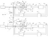
图1是根据本发明的一实施例的示例性动力设备布置10的概略图示;Figure 1 is a diagrammatic illustration of an exemplary power plant arrangement 10 according to an embodiment of the invention;
图2是根据本发明的一实施例的图1的动力设备布置10的示例性构造100的概略图示。FIG. 2 is a diagrammatic illustration of an
附图标记:Reference signs:
10 示例性动力设备布置10 EXEMPLARY POWER PLANT ARRANGEMENT
12 主空气压缩机12 main air compressor
14 可变放气阀14 Variable bleed valve
16 系间(inter-train)阀16 Inter-train valves
18 从属(slave)可变放气阀18 slave (slave) variable bleed valve
19 系间管道19 inter-system pipeline
20 涡轮发电机20 turbine generator
22 涡轮轴22 Turbine shaft
24 增压压缩机24 booster compressor
25 空气喷射阀25 Air injection valve
26 压缩环境气流的第一部分26 Compress the first part of the ambient airflow
27 气体控制阀27 Gas control valve
28 燃料流28 fuel flow
30 涡轮压缩机30 turbo compressor
31 次级流动路径31 Secondary flow path
32 涡轮燃烧器32 turbo burner
34 涡轮34 Turbo
36 热回收蒸汽发生器36 Heat recovery steam generator
38 风门38 damper
40 再循环气流冷却器40 recirculating air cooler
42 风机42 fans
44 涡轮压缩机排气44 Turbo compressor exhaust
45 抽气阀45 Extraction valve
47 涡轮旁通阀47 Turbine bypass valve
48 排气抽取点48 exhaust extraction point
49 旁通管道49 bypass pipe
50 再循环气流50 recirculation airflow
52 再循环回路52 recirculation loop
60 从属涡轮发电机60 slave turbine generators
62 从属涡轮轴62 Slave turbine shaft
64 从属增压压缩机64 Slave booster compressor
65 从属空气喷射阀65 Slave Air Injection Valve
66 压缩环境气流的第二部分66 Compress the second part of the ambient airflow
67 从属气体控制阀67 Slave gas control valve
68 从属燃料流68 Slave fuel flow
70 从属涡轮压缩机70 slave turbo compressor
71 从属次级流动路径71 Dependent secondary flow paths
72 从属涡轮燃烧器72 Slave turbo burner
74 从属涡轮74 slave turbine
76 从属热回收蒸汽发生器76 Slave heat recovery steam generator
78 从属风门78 Slave damper
80 从属再循环气流冷却器80 Slave Recirculation Airflow Cooler
82 从属风机82 slave fans
84 从属涡轮压缩机排气84 Slave turbo compressor exhaust
85 从属抽气阀85 Slave extraction valve
87 从属涡轮旁通阀87 Slave turbine bypass valve
88 从属排气抽取点88 Slave exhaust extraction point
89 从属旁通管道89 Slave bypass pipe
90 从属再循环气流90 slave recirculation airflow
92 从属再循环回路92 Slave recirculation loop
100 示例性构造。100 Exemplary configuration.
具体实施方式Detailed ways
在下文的描述中,给出了许多具体细节,以提供对实施例的透彻理解。可在没有这些具体细节中的一个或更多的情况下或者利用其它方法、构件、材料等来实施这些实施例。在其它情况下,未详细示出或描述公知的结构、材料或操作,以避免使实施例的方面变得模糊。In the following description, numerous specific details are given to provide a thorough understanding of the embodiments. The embodiments may be practiced without one or more of these specific details, or with other methods, components, materials, etc. In other instances, well-known structures, materials, or operations are not shown or described in detail to avoid obscuring aspects of the embodiments.
遍及该说明书对“一个实施例”、“一实施例”或“实施例”的谈及意味着结合该实施例描述的特定特征、结构或特点被包括在至少一个实施例中。因此,短语“在一个实施例中”或“在一实施例中”在本说明书全文各处的出现不一定都指同一实施例。此外,特定特征、结构或特点可以任何适当的方式结合在一个或更多实施例中。Reference throughout this specification to "one embodiment," "an embodiment," or "an embodiment" means that a particular feature, structure, or characteristic described in connection with the embodiment is included in at least one embodiment. Thus, appearances of the phrase "in one embodiment" or "in an embodiment" in various places throughout this specification are not necessarily all referring to the same embodiment. Furthermore, the particular features, structures or characteristics may be combined in any suitable manner in one or more embodiments.
发电行业中近期的需求已使得必须开发可构造成基本上消耗空气工作流体中的全部氧气来产生基本上无氧气的排气流的燃气涡轮布置。这种排气流可更容易地适合于使用NOx催化剂的排放减少。此外,这种排气流可由于低氧气浓度而更好地适合于燃烧后碳捕获方案。此外,基本上无氧气的排气流可更容易地适合于增强的油回收应用。Recent demands in the power generation industry have necessitated the development of gas turbine arrangements that can be configured to consume substantially all of the oxygen in the air working fluid to produce a substantially oxygen-free exhaust stream. This exhaust flow may be more readily suitable for emission reduction using aNOx catalyst. Furthermore, such exhaust streams may be better suited for post combustion carbon capture schemes due to the low oxygen concentration. Additionally, a substantially oxygen-free exhaust stream may be more readily suitable for enhanced oil recovery applications.
可通过燃烧系统中的化学计量燃烧来实现来自燃气涡轮的基本上无氧的排气。即,包含氧气的新鲜空气供应可与燃料流匹配,使得燃烧过程接近燃烧化学计量操作。Substantially oxygen-free exhaust from the gas turbine can be achieved by stoichiometric combustion in the combustion system. That is, the supply of fresh air containing oxygen can be matched to the flow of fuel so that the combustion process operates close to combustion stoichiometry.
将甲烷与氧气的化学计量燃烧反应示出如下:The stoichiometric combustion reaction of methane with oxygen is shown below:

化学计量燃烧可引起对于燃气涡轮发动机中采用的材料和冷却技术而言过高的气体温度。为了降低这些高温,可使燃气涡轮排气产物的一部分再循环回到燃烧系统,以降低燃烧温度。理想而言,这种稀释气体也应明显无氧气,以便不会将另外的氧气导入系统中并从而削弱化学计量燃烧的优点。使用化学计量燃烧和再循环排气的燃气涡轮应用被称为化学计量排气再循环(SEGR)。Stoichiometric combustion can cause gas temperatures that are too high for the materials and cooling techniques employed in gas turbine engines. To reduce these high temperatures, a portion of the gas turbine exhaust products may be recirculated back to the combustion system to reduce the combustion temperature. Ideally, this diluent gas should also be significantly free of oxygen, so that no additional oxygen is introduced into the system and thereby impair the advantages of stoichiometric combustion. Gas turbine applications that use stoichiometric combustion and recirculated exhaust gas are known as stoichiometric exhaust gas recirculation (SEGR).
SEGR系统可使用直接供给到燃烧过程中以提供用于燃烧的氧气的高压空气供应。这种空气可由辅助压缩机供应。实际上,辅助压缩机在SEGR燃气涡轮所需的压力和流率下提供空气的能力将不会跨越负载的全部操作范围和系统所经历的环境温度而匹配。辅助压缩机可允许压缩机有时提供比燃气涡轮所需更多的空气。此外,辅助压缩机可设计有始终提供比燃气涡轮所需更多的空气的能力。在一些状况下,可能需要将其中一些由辅助压缩机压缩的空气排出到大气。SEGR systems may use a high pressure air supply that is fed directly into the combustion process to provide oxygen for combustion. This air can be supplied by an auxiliary compressor. In practice, the auxiliary compressor's ability to provide air at the pressure and flow rate required by the SEGR gas turbine will not be matched across the full operating range of the load and ambient temperatures experienced by the system. An auxiliary compressor may allow the compressor to sometimes provide more air than is required by the gas turbine. Furthermore, the auxiliary compressor can be designed with the ability to always provide more air than is required by the gas turbine. Under some conditions, it may be necessary to vent some of the air compressed by the auxiliary compressor to atmosphere.
如下文详细所述,本发明的实施例可用于通过使用SEGR循环来减少燃气涡轮动力设备系统中的排放物,该SEGR循环可实现用于动力产生的基本上化学计量的燃烧反应。SEGR燃气涡轮可构造成以便提供低氧气含量排气。该低氧气含量排气可与NOx还原催化剂一起使用,以提供还可无NOx污染物的排气流。As described in detail below, embodiments of the present invention may be used to reduce emissions in gas turbine power plant systems through the use of a SEGR cycle that enables substantially stoichiometric combustion reactions for power production. SEGR gas turbines may be configured to provide low oxygen exhaust gas. This low oxygen content exhaust may be used with aNOx reduction catalyst to provide an exhaust stream that is also free ofNOx pollutants.
当前公开的主题的实施例包括通过首先使动力设备的一个或更多燃气涡轮上升到恒速无负载操作来起动可使用SEGR循环的燃气涡轮动力设备的能力。如文中所用,术语“恒速无负载”意味着使燃气涡轮在恒定转速(例如,>1000 rpm)下操作并且产生足够的功率以在没有从所附发电机单元施加的任何电负载的情况下至少操作涡轮压缩机。在一些实施例中,在恒速无负载下操作的燃气涡轮可具有全速运行但可不连接至电网的涡轮。Embodiments of the presently disclosed subject matter include the ability to start a gas turbine power plant that may use a SEGR cycle by first ramping one or more gas turbines of the power plant to constant speed no-load operation. As used herein, the term "constant speed no load" means that the gas turbine is operated at a constant rotational speed (e.g., >1000 rpm) and produces enough power without any electrical load applied from the attached generator unit Operate at least the turbo compressor. In some embodiments, a gas turbine operating at constant speed no load may have a turbine running at full speed but may not be connected to the grid.
动力设备布置Power equipment arrangement
现在转到附图且首先参照图1,示出了示例性动力设备布置10。示例性动力设备布置10可包括主空气压缩机12,用于将环境空气压缩成压缩环境气流26的至少第一部分。此外,动力设备布置10可包括可流体连接至主空气压缩机12的涡轮燃烧器32。压缩环境气流26的至少第一部分到涡轮燃烧器32的流可由空气喷射阀25调节。压缩环境气流26的至少第一部分的过量部分可在主空气压缩机12的输出部与通往涡轮燃烧器32的输入部之间泄放。在一些实施例中,压缩环境气流26的至少第一部分可经由可变放气阀14泄放至大气。Turning now to the drawings and referring initially to FIG. 1 , an exemplary power plant arrangement 10 is shown. The exemplary power plant arrangement 10 may include a
涡轮燃烧器32可构造成接收来自主空气压缩机12的压缩环境气流26的至少第一部分、来自涡轮压缩机30的再循环气流50的至少第一部分、以及燃料流28,以形成可燃混合物并燃烧该可燃混合物而生成再循环气流50。在一些实施例中,燃料流28可由气体控制阀27调节以输送燃料流率。此外,动力设备布置10可包括位于涡轮燃烧器32下游的涡轮34。涡轮34可构造成使再循环气流50膨胀,并且可经由涡轮轴22来驱动诸如涡轮发电机20的外部负载以发电。在所示的实施例10中,主空气压缩机12和涡轮压缩机30可经由涡轮轴22通过由涡轮34生成的功率来驱动。
在一些实施例中,主空气压缩机12还可包括可调节的进口导叶,以控制进入主空气压缩机12中的空气流。主空气压缩机的进口导叶可用于调节输送到涡轮燃烧器32的压缩环境气流26的至少第一部分的压力和流率。此外,涡轮压缩机30还可包括可调节的进口导叶,以控制进入涡轮压缩机30中的空气流。涡轮压缩机30的进口导叶可用于调节作为再循环气流50的至少第一部分从涡轮压缩机30输送到涡轮燃烧器32的输出压力和流率。In some embodiments, the
如文中所用,术语“再循环气流”指的是通过可燃混合物在涡轮燃烧器32中燃烧并流经再循环回路52而生成的气流。在一些实施例中,再循环气流可具有低氧气含量。术语“低氧气含量”指的是低于约5 vol%、低于约2 vol%或低于约1 vol%的氧气含量。As used herein, the term “recirculation gas flow” refers to the gas flow generated by combusting a combustible mixture in
如文中所用,术语“燃气涡轮组件”指的是动力设备布置除主空气压缩机12外的全部所列构件。在包括多个主空气压缩机的实施例中,术语“燃气涡轮组件”指的是动力设备布置除多个主空气压缩机外的全部所列构件。As used herein, the term “gas turbine assembly” refers to all listed components of the power plant arrangement except the
在一些实施例中,再循环气流50可从涡轮34经再循环回路52被引向热回收蒸汽发生器36用于生成蒸汽。蒸汽涡轮还可构造成使用来自热回收蒸汽发生器36的蒸汽来生成另外的电力,并且蒸汽涡轮可连接到蒸汽发生器。在一些实施例中,热回收蒸汽发生器36与蒸汽涡轮和蒸汽发生器结合可构造成当再循环气流50的温度在从约200℃至约700℃、从约260℃至约600℃或者从约300℃至约550℃的范围内时生成另外的电力。在一些实施例中,蒸汽涡轮可布置成连接到涡轮轴22。再循环气流50然后可被引导回到再循环回路52中到达再循环气流冷却器40。在仍然其它实施例中,再循环回路52可不包含热回收蒸汽发生器36,并且再循环气流50可代之在从涡轮34离开后被直接导入再循环气流冷却器40中。在其它实施例中,再循环回路52可不包括再循环气流冷却器40。In some embodiments, recycle
在一些实施例中,再循环气流冷却器40可在涡轮34下游的任何位置结合在再循环回路52中。再循环气流冷却器40可构造成将再循环气流50的温度降低到合适的温度,以便经由再循环回路52向下游输送到涡轮压缩机30中。在一些实施例中,合适的温度可低于约66℃,低于约49℃,或者低于约45℃。In some embodiments, the recirculated
在一些实施例中,风机42可流体连接至再循环气流冷却器40上游的再循环回路52。风机42可构造成在经由再循环回路52输送到再循环气流冷却器40中之前提高再循环气流50的压力。In some embodiments,
在一些实施例中,示例性动力设备布置10可包括位于涡轮压缩机30下游的旁通管道49,并且可经由涡轮压缩机排气44与再循环气流50的一部分流体连接。旁通管道49可用于使涡轮压缩机排气44的至少一部分作为具有旁通流率的旁通流绕开涡轮燃烧器32。在一些实施例中,通过旁通管道49的旁通流可由涡轮旁通阀47调节。涡轮旁通阀47可用于调节通过旁通管道49的旁通流率。在一些实施例中,旁通管道49可用于使再循环气流50的至少第二部分绕开涡轮燃烧器32。In some embodiments, the exemplary power plant arrangement 10 may include a
在一些实施例中,旁通流可流体连接至涡轮34下游的再循环回路52。在仍然其它实施例中,进入旁通管道49中的旁通流的一部分可作为抽取流48被抽取并可由抽气阀45调节。In some embodiments, the bypass flow may be fluidly connected to the
在一些实施例中,抽气阀45可在位于涡轮旁通阀47上游或下游的点流体连接至旁通管道49。在一些实施例中,抽取流48可流体连接至一个或更多另外的过程。在一些实施例中,旁通抽气阀45可经由抽取流48流体连接至诸如碳捕获隔离(CCS)系统的气体分离系统。在仍然其它实施例中,气体分离系统可产生浓缩二氧化碳和浓缩氮气的流,两者都具有低氧气含量。In some embodiments,
再循环气流50的过量部分可在涡轮压缩机30的输出部与通往涡轮压缩机30的输入部之间的某处泄放。在一些实施例中,向大气泄放的燃气涡轮可与燃气涡轮组件流体连通,并且可位于涡轮压缩机30的输出部与涡轮压缩机30的输入部之间的任何位置。在一些实施例中,动力设备布置10可包括连接到再循环回路52的风门38。风门38可打开,以向大气泄放一部分再循环气流50。在一些实施例中,再循环气流50的过量部分可从旁通管道49泄放。The excess portion of the recirculated
在一些实施例中,燃气涡轮组件还可包括次级流动路径31,该次级流动路径31可将再循环气流50的至少第三部分作为次级流从涡轮压缩机30输送到涡轮34。次级流可用于冷却和密封涡轮34,包括涡轮34的单独构件,诸如涡轮外罩、涡轮喷嘴、涡轮叶片顶端、涡轮轴承支承壳体等。在冷却和密封涡轮34和任何单独的涡轮构件之后,可将次级流引导到涡轮34的输出部下游的再循环回路52中。In some embodiments, the gas turbine assembly may also include a
如图1所示,在一些实施例中,涡轮轴22可为“冷端驱动”构造,意味着涡轮轴22可在涡轮组件的压缩机端连接到发电机20。在其它实施例中,涡轮轴22可为“热端驱动”构造,意味着涡轮轴22可在涡轮组件的涡轮端连接到发电机20。As shown in FIG. 1 , in some embodiments, the
如文中所用,术语“从属”与术语次级、辅助或另外同义。在下文的实施例中,术语“从属”指的是两个燃气涡轮组件中的第二个,但在下文的实施例中也可指与主燃气涡轮组件一起操作的任何另外的燃气涡轮组件,例如第二燃气涡轮组件。As used herein, the term "subordinate" is synonymous with the terms secondary, auxiliary or otherwise. In the examples below, the term "slave" refers to the second of the two gas turbine assemblies, but may also refer to any additional gas turbine assembly operating with the main gas turbine assembly in the examples below, For example the second gas turbine assembly.
在一些实施例中,主空气压缩机12可向从属涡轮燃烧器72输送压缩环境气体,该从属涡轮燃烧器72可经由系间管道19流体连接至主空气压缩机12。通过系间管道19的压缩环境气体流可由系间阀16进一步调节,以形成压缩环境气流66的至少第二部分。在一些实施例中,压缩环境气流66的至少第二部分可经由从属可变放气阀18向大气泄放。在一些实施例中,压缩环境气流66的至少第二部分到从属涡轮燃烧器72的流可由从属空气喷射阀65调节。In some embodiments,
从属涡轮燃烧器72可构造成接收来自主空气压缩机12的压缩环境气流66的至少第二部分、来自从属涡轮压缩机70的从属再循环流90、以及从属燃料流68,以形成从属可燃混合物并燃烧该从属可燃混合物而生成从属再循环气流90。在一些实施例中,从属燃料流68可由从属气体控制阀67调节以输送从属燃料流率。此外,示例性动力设备布置10可包括位于从属涡轮燃烧器72下游的从属涡轮74。从属涡轮74可构造成使从属再循环气流90膨胀,并且可经由从属涡轮轴62来驱动诸如从属涡轮发电机60的外部负载以发电。The
在一些实施例中,从属涡轮压缩机70还可包括可调节的进口导叶,以控制输送到从属涡轮压缩机70的空气的流率。在一些实施例中,从属涡轮压缩机70的进口导叶可用于调节作为从属再循环气流90从从属涡轮压缩机70输送到从属涡轮燃烧器72的流率和输出压力。In some embodiments, the
如文中所用,术语“从属再循环气流”指的是通过从属可燃混合物在从属涡轮燃烧器72中燃烧并流经从属再循环回路92而生成的气流。在一些实施例中,从属再循环气流90可包括低氧气含量。术语“低氧气含量”指的是低于约5 vol%、低于约2 vol%或者低于约1 vol%的氧气含量。As used herein, the term “slave recirculation gas flow” refers to a gas flow generated by combusting a slave combustible mixture in
在一些实施例中,从属再循环气流90可从从属涡轮燃烧器72经从属再循环回路92被引向从属热回收蒸汽发生器76,用于蒸汽的生成。从属蒸汽涡轮还可构造成使用来自从属热回收蒸汽发生器76的蒸汽来生成另外的电力,并且从属蒸汽涡轮可连接到从属蒸汽发生器。在一些实施例中,从属热回收蒸汽发生器76与从属蒸汽涡轮和从属蒸汽发生器结合可构造成当从属再循环气流90的温度在从约200℃至约700℃、从约260℃至约600℃或从约300℃至约550℃的范围内时生成另外的电力。在一些实施例中,从属蒸汽涡轮可布置成连接到从属涡轮轴62。从属再循环气流90然后可被引导回到从属再循环回路92中到达从属再循环气流冷却器80。在仍然其它实施例中,再循环回路92可不包含从属热回收蒸汽发生器76,并且从属再循环气流90可代之在从从属涡轮74离开后被直接导入从属再循环气流冷却器80中。在其它实施例中,从属再循环回路92可不包括从属再循环气流冷却器80。In some embodiments,
从属再循环气流冷却器80可在从属涡轮74下游的任何位置结合在从属再循环回路92中。从属再循环气流冷却器80可构造成将从属再循环气流90的温度降低到合适的温度,以经由从属再循环回路92向下游输送到从属涡轮压缩机70中。在一些实施例中,合适的温度可低于约66℃,低于约49℃,或者低于约45℃。The slave recirculation airflow cooler 80 may be incorporated in the
在一些实施例中,从属风机82可流体连接至从属再循环气流冷却器80上游的从属再循环回路92。从属风机82可构造成在经由从属再循环回路92输送到从属涡轮压缩机70中之前提高从属再循环气流90的压力。In some embodiments,
在一些实施例中,示例性动力设备布置10可包括位于从属涡轮压缩机70下游且经由从属涡轮压缩机输出流84与从属再循环气流90的一部分流体连接的从属旁通管道89。在一些实施例中,通过从属旁通管道89的从属旁通流可由从属涡轮旁通阀87调节。从属涡轮旁通阀87可用于调节通过从属旁通管道89的从属旁通流率。在一些实施例中,从属再循环气流90的至少第二部分可作为具有从属旁通流率的从属旁通流绕开从属涡轮燃烧器70。In some embodiments, the exemplary power plant arrangement 10 may include a
在一些实施例中,从属旁通流可流体连接至涡轮74下游的从属再循环回路92。在仍然其它实施例中,进入从属旁通管道89中的从属旁通流的一部分可作为从属抽取流88被抽取并由从属抽气阀85调节。In some embodiments, the slave bypass flow may be fluidly connected to
在一些实施例中,从属旁通阀85可在位于从属涡轮旁通阀87上游或下游的点流体连接至从属旁通管道89。在一些实施例中,从属旁通流可被输送到一个或更多另外的过程。在一些实施例中,从属旁通抽气阀85可经由从属抽取流88流体连接至诸如碳捕获隔离(CCS)系统的从属气体分离系统。在仍然其它实施例中,从属气体分离系统可产生浓缩二氧化碳和浓缩氮气的流,两者都具有低氧气含量。In some embodiments,
在一些实施例中,向大气泄放的从属燃气涡轮可与从属燃气涡轮组件流体连通,并且可位于从属涡轮压缩机70的输出部与从属涡轮压缩机70的输入部之间的任何位置。在一些实施例中,动力设备布置10可包括连接到从属再循环回路92的从属风门78。从属风门78可打开,以向大气泄放一部分从属再循环气流90。在一些实施例中,从属再循环气流90的过量部分可从从属旁通管道89泄放。In some embodiments, the slave gas turbine vented to atmosphere may be in fluid communication with the slave gas turbine assembly and may be located anywhere between the output of the
在一些实施例中,燃气涡轮组件还可包括从属次级流动路径71,该从属次级流动路径71可将从属再循环气流90的第三部分作为从属次级流从从属涡轮压缩机70输送到从属涡轮74。从属次级流可用于冷却和密封从属涡轮74,包括从属涡轮74的单独构件,诸如涡轮外罩、涡轮喷嘴、涡轮叶片顶端、涡轮轴承支承壳体等。在冷却和密封从属涡轮74和任何单独的涡轮构件之后,从属次级流可被引导到从属涡轮74下游的从属再循环回路92中。In some embodiments, the gas turbine assembly may also include a slave
如图1所示,在一些实施例中,从属涡轮轴62可为“冷端驱动”构造,意味着从属涡轮轴62可在涡轮组件的压缩机端连接到从属发电机60。在其它实施例中,从属涡轮轴62可为“热端驱动”构造,意味着从属涡轮轴62可在涡轮组件的涡轮端连接到从属发电机60。As shown in FIG. 1 , in some embodiments, the
图2是图1的示例性动力设备布置10的示例性构造100的概略图示。如参考图1所述,增压压缩机24可结合在主空气压缩机12下游并与主空气压缩机12流体连接,并且结合在涡轮燃烧器32上游并与涡轮燃烧器32流体连接。增压压缩机24可在输送到涡轮燃烧器32中之前进一步压缩压缩环境气流26的至少第一部分。类似地,从属增压压缩机64可结合在主空气压缩机12下游并与主空气压缩机12流体连接,并且结合在从属涡轮燃烧器72上游并与从属涡轮燃烧器72流体连接。从属增压压缩机64可在输送到从属涡轮燃烧器72中之前进一步压缩压缩环境气流66的至少第二部分。FIG. 2 is a diagrammatic illustration of an
在一些实施例中,动力设备布置包括一个燃气涡轮组件。在其它实施例中,动力设备布置包括由系间管道19流体连接的两个燃气涡轮组件。如文中所用,术语“系间管道”可指两个或更多燃气涡轮组件与一个或更多主空气压缩机之间的流体连接。在仍然其它实施例中,动力设备布置包括三个或更多燃气涡轮组件和一个或更多另外的主空气压缩机,其中另外的主空气压缩机彼此流体连接并与燃气涡轮组件流体连接。在又其它实施例中,动力设备布置构造成用于基本上化学计量燃烧。在仍然其它实施例中,动力设备布置构造成用于基本上零排放发电。In some embodiments, the power plant arrangement includes a gas turbine assembly. In other embodiments, the power plant arrangement includes two gas turbine assemblies fluidly connected by intersystem
在一些实施例中,燃料流28和/或从属燃料流68可包括有机气体,包括但不限于甲烷、丙烷和/或丁烷。在仍然其它实施例中,燃料流28和/或从属燃料流68可包括有机液体,包括但不限于甲醇和/或乙醇。在又其它实施例中,燃料流28和/或从属燃料流68可包括从诸如煤的固体含碳材料获得的燃料源。In some embodiments, fuel stream 28 and/or
用于操作动力设备的方法Method for operating powered equipment
在一些实施例中,提供了一种用于操作示例性动力设备布置10的方法,其中系间阀16可关闭。在操作中,环境空气可由主空气压缩机12压缩,以形成具有压缩环境气体流率的压缩环境气流26的至少第一部分。压缩环境气流26的至少第一部分可从主空气压缩机12输送到涡轮燃烧器32并可由空气喷射阀25调节。压缩环境气流26的至少第一部分的流还可由可变放气阀14调节。In some embodiments, a method for operating the exemplary power-plant arrangement 10 is provided wherein the
压缩环境气流的至少第一部分可在涡轮燃烧器32中与再循环气流50的至少第一部分和燃料流28混合而形成可燃混合物。燃料流28的流率可由气体控制阀27调节。可燃混合物然后可在涡轮燃烧器32中被点燃并燃烧,从而形成可驱动涡轮34和涡轮压缩机30两者以产生涡轮功率的再循环气流50。At least a first portion of the compressed ambient airflow may mix with at least a first portion of the recirculated
如文中所用,术语“驱动”和“驱动的”意味着再循环气流50在涡轮34中膨胀从而导致涡轮34旋转。涡轮34经由涡轮轴22连接到涡轮压缩机30,因此涡轮34的旋转导致了涡轮压缩机30的旋转。涡轮轴22也可在涡轮发电机20中旋转并且还可发电。As used herein, the terms "driven" and "driven" mean that the recirculated
如图1所示,在一些实施例中,涡轮轴22可为“冷端驱动”构造,意味着涡轮轴22可在涡轮组件的压缩机端连接到发电机20。在其它实施例中,涡轮轴22可为“热端驱动”构造,意味着涡轮轴22可在涡轮组件的涡轮端连接到发电机20。As shown in FIG. 1 , in some embodiments, the
在一些实施例中,再循环气流50的至少一部分可再循环通过再循环回路52。再循环回路52可将涡轮34的输出部与涡轮压缩机30的输入部流体连接。再循环气流50还可经过热回收蒸汽发生器36、再循环气流冷却器40和涡轮风机42从涡轮34的输出部来到涡轮压缩机30的输入部。In some embodiments, at least a portion of the recirculated
再循环气流50的过量部分(如果有的话)可在涡轮压缩机30的输出部与通往涡轮压缩机30的输入部之间的位置从系统泄放。泄放步骤可用于防止燃气涡轮组件的过压。在一些实施例中,泄放步骤可用于降低从涡轮压缩机30输送到涡轮燃烧器32的再循环气流50的压力。在一些实施例中,该操作方法还可包括向大气打开可流体连接至再循环回路52的风门38。Excess portions, if any, of the recirculated
在一些实施例中,涡轮压缩机30的排气的至少一部分可经由旁通管道49绕开涡轮燃烧器32。如文中所用,涡轮压缩机30的“排气”可为压缩再循环气流50从涡轮压缩机30的输出。旁通流率可由涡轮旁通阀47调节。在一些实施例中,旁通管道49可将旁通流输送到涡轮34下游的再循环回路52。在一些实施例中,再循环气流50的至少第二部分可作为具有从属旁通流率的从属旁通流绕开从属涡轮燃烧器32。In some embodiments, at least a portion of exhaust gas from
在一些实施例中,进入旁通管道49中的旁通流的一部分可作为抽取流48被抽取并且可由抽气阀45调节。在一些实施例中,抽气阀45可在位于涡轮旁通阀47上游或下游的点流体连接至旁通管道49。在一些实施例中,旁通流可被引向第二过程。在一些实施例中,旁通流的至少一部分可被输送到气体分离系统。在一些实施例中,旁通抽气阀45可经由抽取流48流体连接至诸如碳捕获隔离(CCS)系统的气体分离系统。在仍然其它实施例中,气体分离系统可产生浓缩二氧化碳和浓缩氮气的流,两者都具有低氧气含量。In some embodiments, a portion of the bypass flow into
在一些实施例中,燃气涡轮组件还可包括次级流动路径31,该次级流动路径31可将再循环气流50的至少第三部分作为次级流从涡轮压缩机30输送到涡轮34。次级流可用于冷却和密封涡轮34,包括涡轮34的单独构件,诸如涡轮外罩、涡轮喷嘴、涡轮叶片顶端、涡轮轴承支承壳体等。在冷却和密封涡轮34和任何单独的涡轮构件之后,可将次级流引导到涡轮34的输出部附近的再循环回路52中。In some embodiments, the gas turbine assembly may also include a
在一些实施例中,通过可燃混合物的燃烧而生成的涡轮功率可用于使涡轮轴22旋转,该涡轮轴22可构造成当在涡轮发电机20中旋转时发电。在一些实施例中,可使用基本上化学计量燃烧来发电。In some embodiments, turbine power generated by combustion of the combustible mixture may be used to rotate a
在仍然其它实施例中,提供了一种用于操作示例性动力设备构造100的方法,并且该方法可包括增压压缩机24的使用,该增压压缩机24可结合在主空气压缩机12下游并与主空气压缩机12流体连接,并且结合在涡轮燃烧器32上游并与涡轮燃烧器32流体连接。增压压缩机24可在输送到涡轮燃烧器32中之前进一步压缩压缩环境气流26的至少第一部分。增压压缩机24的排气可被输送到涡轮燃烧器32。在一些实施例中,增压压缩机24的排气可由空气喷射阀25调节。In still other embodiments, a method for operating the exemplary
用于在恒速无负载下操作动力设备的方法Method for operating powered equipment at constant speed and without load
在另一实施例中,提供了一种用于在恒速无负载下操作示例性动力设备布置10的方法,其中系间阀16可关闭。In another embodiment, a method for operating the exemplary power-plant arrangement 10 at constant speed and no load is provided, wherein the
恒速无负载操作可考虑用于操作的若干因素。第一,由涡轮34产生的功率应该等于主空气压缩机12(如果附接到涡轮轴22)所消耗的功率加涡轮压缩机30所消耗的功率。第二,燃气涡轮组件的排气温度可被维持在合适的温度,以使热回收蒸汽发生器36能够操作。第三,进入涡轮燃烧器32的压缩环境气流26的至少第一部分的压力应该大于或基本上等于从涡轮压缩机30进入涡轮燃烧器32的再循环气流50的至少第一部分的压力。第四,压缩环境气流26的至少第一部分与再循环气流50的至少第一部分的组合应该存在充分的氧气,使得燃烧可在涡轮燃烧器32中进行而不会贫油熄火。Constant speed no load operation may consider several factors for operation. First, the power produced by the
此外,上文在章节“动力设备布置”中所述的设备的每一个元件都可影响恒速无负载操作。在恒速无负载操作时,涡轮34以恒定速度旋转,但涡轮发电机20未接合而发电。主空气压缩机12可具有设定成允许匹配或超过来自涡轮压缩机30的流的压力所需的最低流量的进口导叶。涡轮压缩机30可具有设定成允许向涡轮燃烧器32提供主空气压缩机12未提供的任何必要的剩余流所需的最低流量的进口导叶。可变放气阀14可关闭。系间阀16可关闭。燃料流28的燃料流率可结合压缩环境气流26的至少第一部分和再循环气流50的至少第一部分的流率的组合来设定,以通过燃烧提供充分的涡轮功率。此外,再循环气流50的过量部分可从燃气涡轮组件泄放,使得组件不会过压。Furthermore, each element of the plant described above in the section "Power Plant Arrangement" can affect constant speed no-load operation. In constant speed no load operation, the
在下文详细说明的一些实施例中,旁通管道49可用于将来自涡轮压缩机30的额外压力作为旁通流“排出”。旁通流可由涡轮旁通阀47调节。跨过涡轮34的流量可等于来自涡轮压缩机30的流率乘以一减涡轮旁通阀打开百分比,加上压缩环境气流26的至少第一部分的流率加上燃料流26的流率。于是,涡轮功率可等于跨过涡轮34的流量乘以跨过涡轮34抽取的比功。从涡轮34抽取的比功可与跨过涡轮34的压降和温降成正比。跨过涡轮区段的温降可受涡轮34进口温度影响,涡轮34进口温度可受进入涡轮燃烧器32中的燃料流影响。In some embodiments, detailed below,
在操作中,环境空气可由主空气压缩机12压缩,以形成具有压缩环境气体流率的压缩环境气流26的至少第一部分。在一些实施例中,通往主空气压缩机12的进口导叶可用于控制压缩环境气体流率,并且可被调节到约30°至约55°、从约35°至约50°或者从约40°至约45°的范围。压缩环境气流26的至少第一部分可从主空气压缩机12输送到涡轮燃烧器32,并且该流可由空气喷射阀25进一步调节。在一些实施例中,压缩环境气流26的至少第一部分的流可另外由可变放气阀14调节。可调节压缩环境气体流率,以控制压缩环境气流26输送到涡轮燃烧器32的压力。In operation, ambient air may be compressed by
压缩环境气流26的至少第一部分可在压力下从主空气压缩机12输送到涡轮燃烧器32,该压力大于或基本上等于作为具有再循环低氧气含量气体流率的再循环气流50的至少第一部分从涡轮压缩机30输送到涡轮燃烧器32的输出压力。燃料流28也可以某一燃料流率输送到涡轮燃烧器32。在实施例中,燃料流率、压缩环境气体流率和再循环气体流率可足以维持涡轮燃烧器32中的燃烧。At least a first portion of the compressed
再循环气流50的至少第一部分具有可被调节的流率。调节再循环气流50的至少第一部分的流率可控制从涡轮压缩机30输送到涡轮燃烧器32的输出压力。在一些实施例中,涡轮压缩机30的进口导叶可用于调节再循环低氧气含量流率和压力。在一些实施例中,可将涡轮压缩机30的进口导叶调节到约35°至约65°、约40°至约60°或约45°至约55°的范围。At least a first portion of the recirculated
在一些实施例中,燃料流28的燃料流率可由气体控制阀27调节,以提供在约10pps至约30pps、约15pps至约25pps或从约18pps至约22pps的范围内的燃料流率。如文中所用,术语“pps”意味着磅每秒并以质量标明流率。In some embodiments, the fuel flow rate of fuel stream 28 may be adjusted by
压缩环境气流26的至少第一部分可在涡轮燃烧器32中与再循环气流50的至少第一部分和燃料流29混合而形成可燃混合物。可燃混合物然后可在涡轮燃烧器32中被点燃并燃烧,从而形成再循环气流50并驱动涡轮34和涡轮压缩机30两者,并且产生至少基本上等于使涡轮压缩机30旋转所需的功率的涡轮功率。如文中所用,术语“驱动”意味着涡轮34和涡轮压缩机30两者都旋转。因此,可燃混合物的燃烧可产生至少基本上等于使涡轮压缩机旋转所需的功率的涡轮功率。At least a first portion of compressed
再循环气流50的至少一部分可再循环通过再循环回路52。再循环回路52可将涡轮34的输出部与涡轮压缩机30的输入部流体连接。再循环气流50还可经过热回收蒸汽发生器36、再循环气流冷却器40和涡轮风机42从涡轮34的输出部来到涡轮压缩机30的输入部。At least a portion of the
在一些实施例中,再循环气流50可被引导通过热回收蒸汽发生器36,用于蒸汽的生成。蒸汽涡轮还可构造成使用来自热回收蒸汽发生器36的蒸汽生成另外的电力,并且蒸汽涡轮可连接到蒸汽发生器。在一些实施例中,热回收蒸汽发生器36可构造成当再循环气流50的温度在从约200℃至约700℃、从约260℃至约600℃或者从约300℃至约550℃的范围内时生成另外的电力。在一些实施例中,蒸汽涡轮可连接到涡轮轴22。In some embodiments, recycle
再循环气流50的过量部分可在涡轮压缩机30的输出部与通往涡轮压缩机30的输入部之间的位置从系统泄放。泄放步骤可用于防止燃气涡轮组件的过压。在一些实施例中,泄放步骤可用于降低从涡轮压缩机30输送到涡轮燃烧器32的再循环气流50的压力。在一些实施例中,泄放方法还可包括向大气打开可流体连接至再循环回路52的风门38。Excess portions of the recirculated
在一些实施例中,涡轮压缩机30的排气的至少第二部分可经由旁通管道49绕开涡轮燃烧器32。如文中所用,涡轮压缩机30的“排气”可为压缩再循环气流50从涡轮压缩机30的输出。此外,旁通管道49可将旁通流输送到涡轮34下游的再循环回路52。在一些实施例中,涡轮压缩机30的排气可作为具有旁通流率的旁通流绕开涡轮燃烧器32,其中该旁通流率可被调节。在一些实施例中,可使用涡轮旁通阀47来调节旁通流率。在一些实施例中,涡轮旁通阀47可构造成以在涡轮压缩机30的输出流率的约20%至约80%、从约30%至约70%或从约40%至约60%的范围内的旁通流率输送旁通流。In some embodiments, at least a second portion of exhaust gas from
在一些实施例中,进入旁通管道49中的旁通流的一部分可作为抽取流48被抽取并且可由抽气阀45调节。在一些实施例中,旁通阀45可在位于涡轮旁通阀47上游或下游的点流体连接至旁通管道49。在一些实施例中,旁通流可被输送到第二过程。在一些实施例中,旁通流的至少一部分可被输送到气体分离系统。在一些实施例中,旁通抽气阀45可经由抽取流48流体连接至诸如碳捕获隔离(CCS)系统的气体分离系统。在仍然其它实施例中,气体分离系统可产生浓缩二氧化碳和浓缩氮气的流,两者都具有低氧气含量。In some embodiments, a portion of the bypass flow into
在一些实施例中,压缩环境气流26的至少第一部分可在可基本上等于从涡轮压缩机30到涡轮燃烧器32的输出压力的压力下输送到涡轮燃烧器32。如文中所用,术语“基本上等于”意味着小于约10%、小于约5%或小于约1%的压差。在一些实施例中,压缩环境气流26的至少第一部分可在可大于或基本上等于从涡轮压缩机30到涡轮燃烧器32的输出压力的压力下输送到涡轮燃烧器32。In some embodiments, at least a first portion of compressed
在一些实施例中,涡轮轴22可将涡轮34连接到涡轮压缩机30。在恒速无负载操作下,通过燃烧可燃混合物产生的涡轮功率可基本上等于使涡轮压缩机30旋转所需的功率。在其它实施例中,涡轮轴22还可连接到主空气压缩机12,其中通过燃烧可燃混合物产生的涡轮功率可基本上等于使涡轮压缩机30和主空气压缩机12两者旋转所需的功率。In some embodiments, the
在一些实施例中,燃气涡轮组件还可包括次级流动路径31,该次级流动路径31可将再循环气流50的至少第三部分作为次级流从涡轮压缩机30输送到涡轮34。次级流可用于冷却和密封涡轮34,包括涡轮34的单独构件,诸如涡轮外罩、涡轮喷嘴、涡轮叶片顶端、涡轮轴承支承壳体等。在冷却和密封涡轮34和任何单独的涡轮构件之后,可将次级流引导到涡轮34的输出部附近的再循环回路52中。In some embodiments, the gas turbine assembly may also include a
在仍然其它实施例中,提供了一种用于在恒速无负载下操作示例性动力设备构造100的方法,并且该方法可包括增压压缩机24的使用,该增压压缩机24可结合在主空气压缩机12下游并与主空气压缩机12流体连接,并且结合在涡轮燃烧器32上游并与涡轮燃烧器32流体连接。增压压缩机24还可在输送到涡轮燃烧器32中之前压缩压缩环境气流26的至少第一部分。增压压缩机24的排气可被输送到涡轮燃烧器32。在一些实施例中,增压压缩机24的排气可由空气喷射阀25调节。In still other embodiments, a method for operating the exemplary
在一些实施例中,该方法包括操作包括一个燃气涡轮组件的动力设备布置。在其它实施例中,该方法包括操作动力设备布置,该动力设备布置包括由系间管道19流体连接的两个燃气涡轮组件。如文中所用,术语“系间管道”可指两个或更多燃气涡轮组件与一个或更多主空气压缩机之间的流体连接。在仍然其它实施例中,该方法包括操作动力设备布置,动力设备布置包括三个或更多燃气涡轮组件和一个或更多另外的主空气压缩机,其中另外的主空气压缩机彼此流体连接并与燃气涡轮组件流体连接。在又其它实施例中,该方法包括操作构造成用于基本上化学计量燃烧的动力设备布置。在仍然其它实施例中,该方法包括操作构造成用于基本上零排放发电的动力设备布置。In some embodiments, the method includes operating a power plant arrangement including a gas turbine assembly. In other embodiments, the method includes operating a power plant arrangement comprising two gas turbine assemblies fluidly connected by an
包括授予Daniel Snook、Lisa Wichmann、Sam Draper和Noemie Dion Ouellet的“Power Plant and Method of Use” (2011年8月25日提交)、授予Daniel Snook、Lisa Wichmann、Sam Drape、Noemie Dion Ouellet和Scott Rittenhouse的“Power Plant and Method of Operation”(2011年8月25日提交)、授予Daniel Snook, Lisa Wichmann、Sam Draper、Noemie Dion Ouellet和Scott Rittenhouse的“Power Plant Start-Up Method”(2011年8月25日提交)、授予Daniel Snook、Lisa Wichmann、Sam Draper和Noemie Dion Ouellet的“Power Plant and Control Method”(2011年8月25日提交)、授予Predrag Popovic的“Power Plant and Method of Operation”(2011年8月25日提交)、授予Sam Draper and Kenneth Kohl的“Power Plant and Method of Operation”(2011年8月25日提交)、授予Sam Draper的“Power Plant and Method of Operation”(2011年8月25日提交)、授予Sam Draper的“Power Plant and Method of Operation” (2011年8月25日提交)、授予Lisa Wichmann的“Power Plant and Method of Operation”(2011年8月25日提交)以及授予Karl Dean Minto的“Power Plant and Control Method”(2011年8月25日提交)的美国专利申请提供了其它构造和操作方法,这些申请的公开内容通过引用并入本文中。Including "Power Plant and Method of Use" (submitted 25 August 2011) to Daniel Snook, Lisa Wichmann, Sam Draper, and Noemie Dion Ouellet, to Daniel Snook, Lisa Wichmann, Sam Drape, Noemie Dion Ouellet, and Scott Rittenhouse "Power Plant and Method of Operation" (submitted 25 August 2011), "Power Plant Start-Up Method" awarded to Daniel Snook, Lisa Wichmann, Sam Draper, Noemie Dion Ouellet, and Scott Rittenhouse (25 August 2011) submitted), "Power Plant and Control Method" awarded to Daniel Snook, Lisa Wichmann, Sam Draper and Noemie Dion Ouellet (submitted 25 August 2011), "Power Plant and Method of Operation" awarded to Predrag Popovic (August 2011 Submitted on 25 August), "Power Plant and Method of Operation" to Sam Draper and Kenneth Kohl (submitted on 25 August 2011), "Power Plant and Method of Operation" to Sam Draper (25 August 2011 submitted), "Power Plant and Method of Operation" to Sam Draper (submitted 25 August 2011), "Power Plant and Method of Operation" to Lisa Wichmann (submitted 25 August 2011), and to Karl Dean Minto's U.S. Patent Application for "Power Plant and Control Method" (filed August 25, 2011) provides other constructions and methods of operation, the disclosures of which are incorporated herein by reference.
应该显而易见的是,前文仅涉及本发明的优选实施例,并且可在文中作出许多变更和修改而不偏离如由所述权利要求及其等同限定的本发明的精神和范围。It should be apparent that the foregoing relates only to preferred embodiments of the invention and that numerous changes and modifications may be made therein without departing from the spirit and scope of the invention as defined by the appended claims and their equivalents.
Claims (10)
Applications Claiming Priority (3)
| Application Number | Priority Date | Filing Date | Title |
|---|---|---|---|
| US13/217658 | 2011-08-25 | ||
| US13/217,658 | 2011-08-25 | ||
| US13/217,658US8453462B2 (en) | 2011-08-25 | 2011-08-25 | Method of operating a stoichiometric exhaust gas recirculation power plant |
Publications (2)
| Publication Number | Publication Date |
|---|---|
| CN102953817Atrue CN102953817A (en) | 2013-03-06 |
| CN102953817B CN102953817B (en) | 2016-01-20 |
Family
ID=45525318
Family Applications (1)
| Application Number | Title | Priority Date | Filing Date |
|---|---|---|---|
| CN201210307323.6AActiveCN102953817B (en) | 2011-08-25 | 2012-08-27 | Power equipment and operating method |
Country Status (3)
| Country | Link |
|---|---|
| US (1) | US8453462B2 (en) |
| EP (1) | EP2562383B1 (en) |
| CN (1) | CN102953817B (en) |
Cited By (4)
| Publication number | Priority date | Publication date | Assignee | Title |
|---|---|---|---|---|
| CN105986896A (en)* | 2015-03-19 | 2016-10-05 | 通用电气公司 | Power generation system having compressor creating excess air flow |
| CN105986903A (en)* | 2015-03-19 | 2016-10-05 | 通用电气公司 | Power generation system having compressor creating excess air flow and turbo-expander for cooling inlet air |
| CN106884727A (en)* | 2015-12-16 | 2017-06-23 | 通用电气公司 | To the probability control of power output discharge parameter in gas turbine regulation |
| CN113446070A (en)* | 2020-03-25 | 2021-09-28 | 通用电气公司 | Combined cycle power plant and method of controlling emissions therefrom |
Families Citing this family (78)
| Publication number | Priority date | Publication date | Assignee | Title |
|---|---|---|---|---|
| WO2009120779A2 (en) | 2008-03-28 | 2009-10-01 | Exxonmobil Upstream Research Company | Low emission power generation and hydrocarbon recovery systems and methods |
| EP2276559A4 (en) | 2008-03-28 | 2017-10-18 | Exxonmobil Upstream Research Company | Low emission power generation and hydrocarbon recovery systems and methods |
| EA026915B1 (en) | 2008-10-14 | 2017-05-31 | Эксонмобил Апстрим Рисерч Компани | Methods and systems for controlling the products of combustion |
| EP2499332B1 (en) | 2009-11-12 | 2017-05-24 | Exxonmobil Upstream Research Company | Integrated system for power generation and method for low emission hydrocarbon recovery with power generation |
| CN102971508B (en) | 2010-07-02 | 2016-06-01 | 埃克森美孚上游研究公司 | CO2 separation system and method for separating CO2 |
| US20130104562A1 (en)* | 2010-07-02 | 2013-05-02 | Russell H. Oelfke | Low Emission Tripe-Cycle Power Generation Systems and Methods |
| CA2801492C (en) | 2010-07-02 | 2017-09-26 | Exxonmobil Upstream Research Company | Stoichiometric combustion with exhaust gas recirculation and direct contact cooler |
| MX354587B (en) | 2010-07-02 | 2018-03-12 | Exxonmobil Upstream Res Company Star | Stoichiometric combustion of enriched air with exhaust gas recirculation. |
| TWI564475B (en) | 2010-07-02 | 2017-01-01 | 艾克頌美孚上游研究公司 | Low emission triple-cycle power generation systems and methods |
| TWI563165B (en) | 2011-03-22 | 2016-12-21 | Exxonmobil Upstream Res Co | Power generation system and method for generating power |
| TWI564474B (en) | 2011-03-22 | 2017-01-01 | 艾克頌美孚上游研究公司 | Integrated systems for controlling stoichiometric combustion in turbine systems and methods of generating power using the same |
| TWI563166B (en) | 2011-03-22 | 2016-12-21 | Exxonmobil Upstream Res Co | Integrated generation systems and methods for generating power |
| TWI593872B (en) | 2011-03-22 | 2017-08-01 | 艾克頌美孚上游研究公司 | Integrated system and method of generating power |
| US9127598B2 (en)* | 2011-08-25 | 2015-09-08 | General Electric Company | Control method for stoichiometric exhaust gas recirculation power plant |
| US9810050B2 (en) | 2011-12-20 | 2017-11-07 | Exxonmobil Upstream Research Company | Enhanced coal-bed methane production |
| US9353682B2 (en) | 2012-04-12 | 2016-05-31 | General Electric Company | Methods, systems and apparatus relating to combustion turbine power plants with exhaust gas recirculation |
| US20130269356A1 (en)* | 2012-04-12 | 2013-10-17 | General Electric Company | Method and system for controlling a stoichiometric egr system on a regenerative reheat system |
| US20130269355A1 (en)* | 2012-04-12 | 2013-10-17 | General Electric Company | Method and system for controlling an extraction pressure and temperature of a stoichiometric egr system |
| US20130269360A1 (en)* | 2012-04-12 | 2013-10-17 | General Electric Company | Method and system for controlling a powerplant during low-load operations |
| US20130269357A1 (en)* | 2012-04-12 | 2013-10-17 | General Electric Company | Method and system for controlling a secondary flow system |
| US10273880B2 (en) | 2012-04-26 | 2019-04-30 | General Electric Company | System and method of recirculating exhaust gas for use in a plurality of flow paths in a gas turbine engine |
| US9784185B2 (en) | 2012-04-26 | 2017-10-10 | General Electric Company | System and method for cooling a gas turbine with an exhaust gas provided by the gas turbine |
| US9708977B2 (en) | 2012-12-28 | 2017-07-18 | General Electric Company | System and method for reheat in gas turbine with exhaust gas recirculation |
| US10107495B2 (en) | 2012-11-02 | 2018-10-23 | General Electric Company | Gas turbine combustor control system for stoichiometric combustion in the presence of a diluent |
| US9803865B2 (en) | 2012-12-28 | 2017-10-31 | General Electric Company | System and method for a turbine combustor |
| US9611756B2 (en) | 2012-11-02 | 2017-04-04 | General Electric Company | System and method for protecting components in a gas turbine engine with exhaust gas recirculation |
| US10161312B2 (en) | 2012-11-02 | 2018-12-25 | General Electric Company | System and method for diffusion combustion with fuel-diluent mixing in a stoichiometric exhaust gas recirculation gas turbine system |
| US9869279B2 (en) | 2012-11-02 | 2018-01-16 | General Electric Company | System and method for a multi-wall turbine combustor |
| US10215412B2 (en) | 2012-11-02 | 2019-02-26 | General Electric Company | System and method for load control with diffusion combustion in a stoichiometric exhaust gas recirculation gas turbine system |
| US9574496B2 (en) | 2012-12-28 | 2017-02-21 | General Electric Company | System and method for a turbine combustor |
| US9631815B2 (en) | 2012-12-28 | 2017-04-25 | General Electric Company | System and method for a turbine combustor |
| US9599070B2 (en) | 2012-11-02 | 2017-03-21 | General Electric Company | System and method for oxidant compression in a stoichiometric exhaust gas recirculation gas turbine system |
| US10208677B2 (en) | 2012-12-31 | 2019-02-19 | General Electric Company | Gas turbine load control system |
| US9581081B2 (en) | 2013-01-13 | 2017-02-28 | General Electric Company | System and method for protecting components in a gas turbine engine with exhaust gas recirculation |
| US9512759B2 (en) | 2013-02-06 | 2016-12-06 | General Electric Company | System and method for catalyst heat utilization for gas turbine with exhaust gas recirculation |
| TW201502356A (en) | 2013-02-21 | 2015-01-16 | Exxonmobil Upstream Res Co | Reducing oxygen in a gas turbine exhaust |
| US9938861B2 (en) | 2013-02-21 | 2018-04-10 | Exxonmobil Upstream Research Company | Fuel combusting method |
| WO2014133406A1 (en) | 2013-02-28 | 2014-09-04 | General Electric Company | System and method for a turbine combustor |
| US20140250945A1 (en) | 2013-03-08 | 2014-09-11 | Richard A. Huntington | Carbon Dioxide Recovery |
| TW201500635A (en) | 2013-03-08 | 2015-01-01 | Exxonmobil Upstream Res Co | Processing exhaust for use in enhanced oil recovery |
| US9618261B2 (en) | 2013-03-08 | 2017-04-11 | Exxonmobil Upstream Research Company | Power generation and LNG production |
| CA2902479C (en) | 2013-03-08 | 2017-11-07 | Exxonmobil Upstream Research Company | Power generation and methane recovery from methane hydrates |
| US9631542B2 (en) | 2013-06-28 | 2017-04-25 | General Electric Company | System and method for exhausting combustion gases from gas turbine engines |
| US9835089B2 (en) | 2013-06-28 | 2017-12-05 | General Electric Company | System and method for a fuel nozzle |
| US9617914B2 (en) | 2013-06-28 | 2017-04-11 | General Electric Company | Systems and methods for monitoring gas turbine systems having exhaust gas recirculation |
| TWI654368B (en) | 2013-06-28 | 2019-03-21 | 美商艾克頌美孚上游研究公司 | System, method and media for controlling exhaust gas flow in an exhaust gas recirculation gas turbine system |
| US9903588B2 (en) | 2013-07-30 | 2018-02-27 | General Electric Company | System and method for barrier in passage of combustor of gas turbine engine with exhaust gas recirculation |
| US9587510B2 (en) | 2013-07-30 | 2017-03-07 | General Electric Company | System and method for a gas turbine engine sensor |
| US9951658B2 (en) | 2013-07-31 | 2018-04-24 | General Electric Company | System and method for an oxidant heating system |
| US10030588B2 (en) | 2013-12-04 | 2018-07-24 | General Electric Company | Gas turbine combustor diagnostic system and method |
| US9752458B2 (en) | 2013-12-04 | 2017-09-05 | General Electric Company | System and method for a gas turbine engine |
| US10227920B2 (en) | 2014-01-15 | 2019-03-12 | General Electric Company | Gas turbine oxidant separation system |
| US9915200B2 (en) | 2014-01-21 | 2018-03-13 | General Electric Company | System and method for controlling the combustion process in a gas turbine operating with exhaust gas recirculation |
| US9863267B2 (en) | 2014-01-21 | 2018-01-09 | General Electric Company | System and method of control for a gas turbine engine |
| US10079564B2 (en) | 2014-01-27 | 2018-09-18 | General Electric Company | System and method for a stoichiometric exhaust gas recirculation gas turbine system |
| US10047633B2 (en) | 2014-05-16 | 2018-08-14 | General Electric Company | Bearing housing |
| US10060359B2 (en) | 2014-06-30 | 2018-08-28 | General Electric Company | Method and system for combustion control for gas turbine system with exhaust gas recirculation |
| US10655542B2 (en) | 2014-06-30 | 2020-05-19 | General Electric Company | Method and system for startup of gas turbine system drive trains with exhaust gas recirculation |
| US9885290B2 (en) | 2014-06-30 | 2018-02-06 | General Electric Company | Erosion suppression system and method in an exhaust gas recirculation gas turbine system |
| US9819292B2 (en) | 2014-12-31 | 2017-11-14 | General Electric Company | Systems and methods to respond to grid overfrequency events for a stoichiometric exhaust recirculation gas turbine |
| US9869247B2 (en) | 2014-12-31 | 2018-01-16 | General Electric Company | Systems and methods of estimating a combustion equivalence ratio in a gas turbine with exhaust gas recirculation |
| US10788212B2 (en) | 2015-01-12 | 2020-09-29 | General Electric Company | System and method for an oxidant passageway in a gas turbine system with exhaust gas recirculation |
| US10253690B2 (en) | 2015-02-04 | 2019-04-09 | General Electric Company | Turbine system with exhaust gas recirculation, separation and extraction |
| US10316746B2 (en) | 2015-02-04 | 2019-06-11 | General Electric Company | Turbine system with exhaust gas recirculation, separation and extraction |
| US10094566B2 (en) | 2015-02-04 | 2018-10-09 | General Electric Company | Systems and methods for high volumetric oxidant flow in gas turbine engine with exhaust gas recirculation |
| US10267270B2 (en) | 2015-02-06 | 2019-04-23 | General Electric Company | Systems and methods for carbon black production with a gas turbine engine having exhaust gas recirculation |
| US10145269B2 (en) | 2015-03-04 | 2018-12-04 | General Electric Company | System and method for cooling discharge flow |
| US10480792B2 (en) | 2015-03-06 | 2019-11-19 | General Electric Company | Fuel staging in a gas turbine engine |
| US9863284B2 (en)* | 2015-03-19 | 2018-01-09 | General Electric Company | Power generation system having compressor creating excess air flow and cooling fluid injection therefor |
| US9828887B2 (en) | 2015-03-19 | 2017-11-28 | General Electric Company | Power generation system having compressor creating excess air flow and turbo-expander to increase turbine exhaust gas mass flow |
| WO2016183588A2 (en)* | 2015-05-14 | 2016-11-17 | University Of Central Florida Research Foundation, Inc. | Compressor flow extraction apparatus and methods for supercritical co2 oxy-combustion power generation system |
| GB201808852D0 (en)* | 2018-05-31 | 2018-07-18 | Rolls Royce Plc | Gas turbine engine |
| US11274599B2 (en) | 2019-03-27 | 2022-03-15 | Pratt & Whitney Canada Corp. | Air system switching system to allow aero-engines to operate in standby mode |
| US11391219B2 (en) | 2019-04-18 | 2022-07-19 | Pratt & Whitney Canada Corp. | Health monitor for air switching system |
| US11761378B2 (en)* | 2019-05-13 | 2023-09-19 | Rolls-Royce Corporation | Bleed air charged cooling system with turbo-generator |
| US11859563B2 (en) | 2019-05-31 | 2024-01-02 | Pratt & Whitney Canada Corp. | Air system of multi-engine aircraft |
| US11274611B2 (en) | 2019-05-31 | 2022-03-15 | Pratt & Whitney Canada Corp. | Control logic for gas turbine engine fuel economy |
| US11326525B2 (en)* | 2019-10-11 | 2022-05-10 | Pratt & Whitney Canada Corp. | Aircraft bleed air systems and methods |
Citations (6)
| Publication number | Priority date | Publication date | Assignee | Title |
|---|---|---|---|---|
| CN1348528A (en)* | 1999-03-11 | 2002-05-08 | Alm开发公司 | Method of operation of a gas turbine engine power plant and a gas turbine enging power plant |
| CN1959085A (en)* | 2005-07-08 | 2007-05-09 | 通用电气公司 | Systems and methods for power generation with carbon dioxide isolation |
| EP1871993A1 (en)* | 2005-04-05 | 2008-01-02 | Sargas AS | Low co2 thermal powerplant |
| US20080104938A1 (en)* | 2006-11-07 | 2008-05-08 | General Electric Company | Systems and methods for power generation with carbon dioxide isolation |
| CN101201171A (en)* | 2006-12-11 | 2008-06-18 | 通用电气公司 | Method and system for reducing CO2 emissions in a combustion stream |
| DE102009003610A1 (en)* | 2008-05-15 | 2009-11-19 | General Electric Co. | Dry three-way catalytic reduction of gas turbine NOx |
Family Cites Families (79)
| Publication number | Priority date | Publication date | Assignee | Title |
|---|---|---|---|---|
| US2621475A (en) | 1946-06-13 | 1952-12-16 | Phillips Petroleum Co | Operation of multistage combustion gas turbines |
| US2646663A (en) | 1949-08-31 | 1953-07-28 | Rateau Soc | Semiopen circuit gas-turbine engine |
| US3685287A (en) | 1970-12-08 | 1972-08-22 | Mcculloch Corp | Re-entry type integrated gas turbine engine and method of operation |
| US3771969A (en) | 1971-05-10 | 1973-11-13 | Arvin Ind Inc | Catalytic converter |
| US3875380A (en) | 1971-12-06 | 1975-04-01 | Westinghouse Electric Corp | Industrial gas turbine power plant control system and method implementing improved dual fuel scheduling algorithm permitting automatic fuel transfer under load |
| US3866411A (en)* | 1973-12-27 | 1975-02-18 | Texaco Inc | Gas turbine process utilizing purified fuel and recirculated flue gases |
| US3949548A (en) | 1974-06-13 | 1976-04-13 | Lockwood Jr Hanford N | Gas turbine regeneration system |
| US4271664A (en) | 1977-07-21 | 1981-06-09 | Hydragon Corporation | Turbine engine with exhaust gas recirculation |
| US4267692A (en) | 1979-05-07 | 1981-05-19 | Hydragon Corporation | Combined gas turbine-rankine turbine power plant |
| US4313300A (en) | 1980-01-21 | 1982-02-02 | General Electric Company | NOx reduction in a combined gas-steam power plant |
| US4330038A (en) | 1980-05-14 | 1982-05-18 | Zimpro-Aec Ltd. | Oil reclamation process |
| US4434613A (en) | 1981-09-02 | 1984-03-06 | General Electric Company | Closed cycle gas turbine for gaseous production |
| US4492085A (en) | 1982-08-09 | 1985-01-08 | General Electric Company | Gas turbine power plant |
| DE3320228A1 (en) | 1983-06-03 | 1984-12-06 | Kraftwerk Union AG, 4330 Mülheim | POWER PLANT WITH AN INTEGRATED COAL GASIFICATION PLANT |
| US4528811A (en) | 1983-06-03 | 1985-07-16 | General Electric Co. | Closed-cycle gas turbine chemical processor |
| US4533314A (en) | 1983-11-03 | 1985-08-06 | General Electric Company | Method for reducing nitric oxide emissions from a gaseous fuel combustor |
| US4561245A (en) | 1983-11-14 | 1985-12-31 | Atlantic Richfield Company | Turbine anti-icing system |
| US5177954A (en) | 1984-10-10 | 1993-01-12 | Paul Marius A | Gas turbine engine with cooled turbine blades |
| GB8520863D0 (en)* | 1985-08-20 | 1985-09-25 | Howden Eng Ltd | Inert gas production |
| CH681480A5 (en) | 1990-06-07 | 1993-03-31 | Asea Brown Boveri | |
| CH684963A5 (en) | 1991-11-13 | 1995-02-15 | Asea Brown Boveri | Annular combustion chamber. |
| JP3209775B2 (en) | 1992-01-10 | 2001-09-17 | 株式会社日立製作所 | Combined cycle power plant and its operation method |
| DE4223828A1 (en) | 1992-05-27 | 1993-12-02 | Asea Brown Boveri | Method for operating a combustion chamber of a gas turbine |
| US6289666B1 (en)* | 1992-10-27 | 2001-09-18 | Ginter Vast Corporation | High efficiency low pollution hybrid Brayton cycle combustor |
| US5794431A (en) | 1993-07-14 | 1998-08-18 | Hitachi, Ltd. | Exhaust recirculation type combined plant |
| DE4331081A1 (en) | 1993-09-13 | 1995-03-16 | Abb Management Ag | Process for operating a gas turbine plant |
| DE4411624A1 (en) | 1994-04-02 | 1995-10-05 | Abb Management Ag | Combustion chamber with premix burners |
| DE4435322B4 (en) | 1994-10-01 | 2005-05-04 | Alstom | Method and device for shaft seal and for cooling on the exhaust side of an axial flowed gas turbine |
| DE19502796B4 (en) | 1995-01-30 | 2004-10-28 | Alstom | burner |
| US5595059A (en)* | 1995-03-02 | 1997-01-21 | Westingthouse Electric Corporation | Combined cycle power plant with thermochemical recuperation and flue gas recirculation |
| US5724805A (en) | 1995-08-21 | 1998-03-10 | University Of Massachusetts-Lowell | Power plant with carbon dioxide capture and zero pollutant emissions |
| US6105362A (en) | 1995-09-22 | 2000-08-22 | Kabushiki Kaisha Toshiba | Combined cycle power plant with gas turbine cooling system |
| US5822992A (en) | 1995-10-19 | 1998-10-20 | General Electric Company | Low emissions combustor premixer |
| US5809768A (en) | 1997-04-08 | 1998-09-22 | Mitsubishi Heavy Industries, Ltd. | Hydrogen-oxygen combustion turbine plant |
| US6256976B1 (en) | 1997-06-27 | 2001-07-10 | Hitachi, Ltd. | Exhaust gas recirculation type combined plant |
| US6050082A (en) | 1998-01-20 | 2000-04-18 | General Electric Company | Intercooled gas turbine engine with integral air bottoming cycle |
| EP0939199B1 (en)* | 1998-02-25 | 2004-03-31 | ALSTOM Technology Ltd | Power plant and process for operating a power plant with a CO2-cycle |
| DK0953748T3 (en) | 1998-04-28 | 2004-06-07 | Alstom Switzerland Ltd | Power plant with a CO2 process |
| US6082093A (en) | 1998-05-27 | 2000-07-04 | Solar Turbines Inc. | Combustion air control system for a gas turbine engine |
| JP3783442B2 (en)* | 1999-01-08 | 2006-06-07 | 株式会社日立製作所 | Control method of gas turbine |
| US6389793B1 (en) | 2000-04-19 | 2002-05-21 | General Electric Company | Combustion turbine cooling media supply system and related method |
| US6622470B2 (en)* | 2000-05-12 | 2003-09-23 | Clean Energy Systems, Inc. | Semi-closed brayton cycle gas turbine power systems |
| US6430915B1 (en) | 2000-08-31 | 2002-08-13 | Siemens Westinghouse Power Corporation | Flow balanced gas turbine power plant |
| US6651421B2 (en)* | 2000-10-02 | 2003-11-25 | Richard R. Coleman | Coleman regenerative engine with exhaust gas water extraction |
| DE50208649D1 (en) | 2001-04-06 | 2006-12-21 | Alstom Technology Ltd | PROCESS FOR MAINTAINING A KOMBIKRAFTWERKES |
| WO2002095852A2 (en) | 2001-05-24 | 2002-11-28 | Clean Energy Systems, Inc. | Combined fuel cell and fuel combustion power generation systems |
| WO2003027461A1 (en) | 2001-09-24 | 2003-04-03 | Alstom Technology Ltd | Gas turbine system for working fluid in the form of a carbon dioxide/water mixture |
| US20040011057A1 (en) | 2002-07-16 | 2004-01-22 | Siemens Westinghouse Power Corporation | Ultra-low emission power plant |
| EP1549881B1 (en) | 2002-10-10 | 2016-02-03 | LPP Combustion, LLC | System for vaporization of liquid fuels for combustion and method of use |
| US7490472B2 (en)* | 2003-02-11 | 2009-02-17 | Statoil Asa | Efficient combined cycle power plant with CO2 capture and a combustor arrangement with separate flows |
| GB2401403B (en)* | 2003-05-08 | 2006-05-31 | Rolls Royce Plc | Carbon dioxide recirculation |
| DE10325111A1 (en) | 2003-06-02 | 2005-01-05 | Alstom Technology Ltd | Method for generating energy in a gas turbine comprehensive power generation plant and power plant for performing the method |
| US7007487B2 (en) | 2003-07-31 | 2006-03-07 | Mes International, Inc. | Recuperated gas turbine engine system and method employing catalytic combustion |
| US7032388B2 (en) | 2003-11-17 | 2006-04-25 | General Electric Company | Method and system for incorporating an emission sensor into a gas turbine controller |
| DE10360951A1 (en) | 2003-12-23 | 2005-07-28 | Alstom Technology Ltd | Thermal power plant with sequential combustion and reduced CO2 emissions and method of operating such a plant |
| US7124591B2 (en)* | 2004-01-09 | 2006-10-24 | Siemens Power Generation, Inc. | Method for operating a gas turbine |
| US20080193886A1 (en) | 2004-02-10 | 2008-08-14 | Ebara Corporation | Combustion Apparatus |
| DE102004039164A1 (en)* | 2004-08-11 | 2006-03-02 | Alstom Technology Ltd | Method for generating energy in a gas turbine comprehensive power generation plant and power generation plant for performing the method |
| JP2006118391A (en) | 2004-10-20 | 2006-05-11 | Mitsubishi Heavy Ind Ltd | Control device for extracted air boosting facility in integrated gasification combined cycle plant |
| US7383686B2 (en) | 2004-12-13 | 2008-06-10 | Honeywell International Inc. | Secondary flow, high pressure turbine module cooling air system for recuperated gas turbine engines |
| DE102005015151A1 (en) | 2005-03-31 | 2006-10-26 | Alstom Technology Ltd. | Gas turbine system for power station, has control device to control volume flow and/or temperature of combustion exhaust gas, such that fresh gas-exhaust gas-mixture entering into compressor of turbo group has preset reference temperature |
| FR2891013B1 (en) | 2005-09-16 | 2011-01-14 | Inst Francais Du Petrole | GENERATION OF ENERGY BY GAS TURBINE WITHOUT C02 EMISSION |
| US7523602B2 (en) | 2005-09-27 | 2009-04-28 | United Technologies Corporation | Turbine exhaust catalyst |
| US7726114B2 (en)* | 2005-12-07 | 2010-06-01 | General Electric Company | Integrated combustor-heat exchanger and systems for power generation using the same |
| US7650744B2 (en) | 2006-03-24 | 2010-01-26 | General Electric Company | Systems and methods of reducing NOx emissions in gas turbine systems and internal combustion engines |
| US7895822B2 (en) | 2006-11-07 | 2011-03-01 | General Electric Company | Systems and methods for power generation with carbon dioxide isolation |
| US8850789B2 (en) | 2007-06-13 | 2014-10-07 | General Electric Company | Systems and methods for power generation with exhaust gas recirculation |
| WO2008155242A1 (en) | 2007-06-19 | 2008-12-24 | Alstom Technology Ltd | Gas turbine system having exhaust gas recirculation |
| US9404418B2 (en) | 2007-09-28 | 2016-08-02 | General Electric Company | Low emission turbine system and method |
| EP2078827A1 (en) | 2008-01-11 | 2009-07-15 | ALSTOM Technology Ltd | Power plant with CO2 capture and compression |
| US20090280003A1 (en) | 2008-05-08 | 2009-11-12 | Jesse Jay Schriner | Method and system for monitoring particulate |
| US20090301054A1 (en)* | 2008-06-04 | 2009-12-10 | Simpson Stanley F | Turbine system having exhaust gas recirculation and reheat |
| US20100018218A1 (en) | 2008-07-25 | 2010-01-28 | Riley Horace E | Power plant with emissions recovery |
| US8015822B2 (en) | 2008-11-21 | 2011-09-13 | General Electric Company | Method for controlling an exhaust gas recirculation system |
| US20100170218A1 (en) | 2009-01-05 | 2010-07-08 | General Electric Company | Method for expanding compressor discharge bleed air |
| US20100175386A1 (en) | 2009-01-09 | 2010-07-15 | General Electric Company | Premixed partial oxidation syngas generation and gas turbine system |
| US20100180565A1 (en) | 2009-01-16 | 2010-07-22 | General Electric Company | Methods for increasing carbon dioxide content in gas turbine exhaust and systems for achieving the same |
| US20110138766A1 (en) | 2009-12-15 | 2011-06-16 | General Electric Company | System and method of improving emission performance of a gas turbine |
| CH703218A1 (en) | 2010-05-26 | 2011-11-30 | Alstom Technology Ltd | Method of operating a combined cycle with flue gas recirculation and power plant. |
- 2011
- 2011-08-25USUS13/217,658patent/US8453462B2/enactiveActive
- 2012
- 2012-08-16EPEP12180613.7Apatent/EP2562383B1/enactiveActive
- 2012-08-27CNCN201210307323.6Apatent/CN102953817B/enactiveActive
Patent Citations (6)
| Publication number | Priority date | Publication date | Assignee | Title |
|---|---|---|---|---|
| CN1348528A (en)* | 1999-03-11 | 2002-05-08 | Alm开发公司 | Method of operation of a gas turbine engine power plant and a gas turbine enging power plant |
| EP1871993A1 (en)* | 2005-04-05 | 2008-01-02 | Sargas AS | Low co2 thermal powerplant |
| CN1959085A (en)* | 2005-07-08 | 2007-05-09 | 通用电气公司 | Systems and methods for power generation with carbon dioxide isolation |
| US20080104938A1 (en)* | 2006-11-07 | 2008-05-08 | General Electric Company | Systems and methods for power generation with carbon dioxide isolation |
| CN101201171A (en)* | 2006-12-11 | 2008-06-18 | 通用电气公司 | Method and system for reducing CO2 emissions in a combustion stream |
| DE102009003610A1 (en)* | 2008-05-15 | 2009-11-19 | General Electric Co. | Dry three-way catalytic reduction of gas turbine NOx |
Cited By (5)
| Publication number | Priority date | Publication date | Assignee | Title |
|---|---|---|---|---|
| CN105986896A (en)* | 2015-03-19 | 2016-10-05 | 通用电气公司 | Power generation system having compressor creating excess air flow |
| CN105986903A (en)* | 2015-03-19 | 2016-10-05 | 通用电气公司 | Power generation system having compressor creating excess air flow and turbo-expander for cooling inlet air |
| CN106884727A (en)* | 2015-12-16 | 2017-06-23 | 通用电气公司 | To the probability control of power output discharge parameter in gas turbine regulation |
| CN106884727B (en)* | 2015-12-16 | 2021-03-16 | 通用电气公司 | Probabilistic control of power output-emission parameters in gas turbine regulation |
| CN113446070A (en)* | 2020-03-25 | 2021-09-28 | 通用电气公司 | Combined cycle power plant and method of controlling emissions therefrom |
Also Published As
| Publication number | Publication date |
|---|---|
| US8453462B2 (en) | 2013-06-04 |
| EP2562383B1 (en) | 2020-11-25 |
| EP2562383A3 (en) | 2018-01-03 |
| US20120023962A1 (en) | 2012-02-02 |
| EP2562383A2 (en) | 2013-02-27 |
| CN102953817B (en) | 2016-01-20 |
Similar Documents
| Publication | Publication Date | Title |
|---|---|---|
| CN102953817B (en) | Power equipment and operating method | |
| US8347600B2 (en) | Power plant and method of operation | |
| CN102953814B (en) | Power device and using method | |
| CN102953834B (en) | Power station and controlling method | |
| US8266883B2 (en) | Power plant start-up method and method of venting the power plant | |
| US20120023954A1 (en) | Power plant and method of operation | |
| US8713947B2 (en) | Power plant with gas separation system | |
| US8453461B2 (en) | Power plant and method of operation | |
| US8245492B2 (en) | Power plant and method of operation | |
| EP2562391B1 (en) | Gas turbine power plant arrangement and controll method | |
| US8205455B2 (en) | Power plant and method of operation | |
| CN103452671B (en) | GTC entrance pressurizes and flow control system | |
| JP6615133B2 (en) | Method and system for starting a gas turbine system drive train with exhaust recirculation |
Legal Events
| Date | Code | Title | Description |
|---|---|---|---|
| C06 | Publication | ||
| PB01 | Publication | ||
| C10 | Entry into substantive examination | ||
| SE01 | Entry into force of request for substantive examination | ||
| C14 | Grant of patent or utility model | ||
| GR01 | Patent grant | ||
| TR01 | Transfer of patent right | ||
| TR01 | Transfer of patent right | Effective date of registration:20231226 Address after:Swiss Baden Patentee after:GENERAL ELECTRIC CO. LTD. Address before:New York State, USA Patentee before:General Electric Co. |