CN102939516A - An electromagnetic method of sensing the relative position between two items using a coupled tuned circuit - Google Patents
An electromagnetic method of sensing the relative position between two items using a coupled tuned circuitDownload PDFInfo
- Publication number
- CN102939516A CN102939516ACN2011800294438ACN201180029443ACN102939516ACN 102939516 ACN102939516 ACN 102939516ACN 2011800294438 ACN2011800294438 ACN 2011800294438ACN 201180029443 ACN201180029443 ACN 201180029443ACN 102939516 ACN102939516 ACN 102939516A
- Authority
- CN
- China
- Prior art keywords
- coupling
- circuits
- amplitude
- circuit
- tuned
- Prior art date
- Legal status (The legal status is an assumption and is not a legal conclusion. Google has not performed a legal analysis and makes no representation as to the accuracy of the status listed.)
- Granted
Links
Images


Classifications
- G—PHYSICS
- G01—MEASURING; TESTING
- G01R—MEASURING ELECTRIC VARIABLES; MEASURING MAGNETIC VARIABLES
- G01R23/00—Arrangements for measuring frequencies; Arrangements for analysing frequency spectra
- G01R23/02—Arrangements for measuring frequency, e.g. pulse repetition rate; Arrangements for measuring period of current or voltage
- G01R23/06—Arrangements for measuring frequency, e.g. pulse repetition rate; Arrangements for measuring period of current or voltage by converting frequency into an amplitude of current or voltage
- G01R23/07—Arrangements for measuring frequency, e.g. pulse repetition rate; Arrangements for measuring period of current or voltage by converting frequency into an amplitude of current or voltage using response of circuits tuned on resonance, e.g. grid-drip meter
- G—PHYSICS
- G01—MEASURING; TESTING
- G01B—MEASURING LENGTH, THICKNESS OR SIMILAR LINEAR DIMENSIONS; MEASURING ANGLES; MEASURING AREAS; MEASURING IRREGULARITIES OF SURFACES OR CONTOURS
- G01B7/00—Measuring arrangements characterised by the use of electric or magnetic techniques
- G01B7/003—Measuring arrangements characterised by the use of electric or magnetic techniques for measuring position, not involving coordinate determination
- G—PHYSICS
- G01—MEASURING; TESTING
- G01B—MEASURING LENGTH, THICKNESS OR SIMILAR LINEAR DIMENSIONS; MEASURING ANGLES; MEASURING AREAS; MEASURING IRREGULARITIES OF SURFACES OR CONTOURS
- G01B7/00—Measuring arrangements characterised by the use of electric or magnetic techniques
- G01B7/30—Measuring arrangements characterised by the use of electric or magnetic techniques for measuring angles or tapers; for testing the alignment of axes
- G—PHYSICS
- G01—MEASURING; TESTING
- G01D—MEASURING NOT SPECIALLY ADAPTED FOR A SPECIFIC VARIABLE; ARRANGEMENTS FOR MEASURING TWO OR MORE VARIABLES NOT COVERED IN A SINGLE OTHER SUBCLASS; TARIFF METERING APPARATUS; MEASURING OR TESTING NOT OTHERWISE PROVIDED FOR
- G01D5/00—Mechanical means for transferring the output of a sensing member; Means for converting the output of a sensing member to another variable where the form or nature of the sensing member does not constrain the means for converting; Transducers not specially adapted for a specific variable
- G01D5/12—Mechanical means for transferring the output of a sensing member; Means for converting the output of a sensing member to another variable where the form or nature of the sensing member does not constrain the means for converting; Transducers not specially adapted for a specific variable using electric or magnetic means
- G01D5/14—Mechanical means for transferring the output of a sensing member; Means for converting the output of a sensing member to another variable where the form or nature of the sensing member does not constrain the means for converting; Transducers not specially adapted for a specific variable using electric or magnetic means influencing the magnitude of a current or voltage
- G01D5/20—Mechanical means for transferring the output of a sensing member; Means for converting the output of a sensing member to another variable where the form or nature of the sensing member does not constrain the means for converting; Transducers not specially adapted for a specific variable using electric or magnetic means influencing the magnitude of a current or voltage by varying inductance, e.g. by a movable armature
- G01D5/2006—Mechanical means for transferring the output of a sensing member; Means for converting the output of a sensing member to another variable where the form or nature of the sensing member does not constrain the means for converting; Transducers not specially adapted for a specific variable using electric or magnetic means influencing the magnitude of a current or voltage by varying inductance, e.g. by a movable armature by influencing the self-induction of one or more coils
- G01D5/202—Mechanical means for transferring the output of a sensing member; Means for converting the output of a sensing member to another variable where the form or nature of the sensing member does not constrain the means for converting; Transducers not specially adapted for a specific variable using electric or magnetic means influencing the magnitude of a current or voltage by varying inductance, e.g. by a movable armature by influencing the self-induction of one or more coils by movable a non-ferromagnetic conductive element
- G01D5/2026—Mechanical means for transferring the output of a sensing member; Means for converting the output of a sensing member to another variable where the form or nature of the sensing member does not constrain the means for converting; Transducers not specially adapted for a specific variable using electric or magnetic means influencing the magnitude of a current or voltage by varying inductance, e.g. by a movable armature by influencing the self-induction of one or more coils by movable a non-ferromagnetic conductive element constituting a short-circuiting element
- G—PHYSICS
- G01—MEASURING; TESTING
- G01D—MEASURING NOT SPECIALLY ADAPTED FOR A SPECIFIC VARIABLE; ARRANGEMENTS FOR MEASURING TWO OR MORE VARIABLES NOT COVERED IN A SINGLE OTHER SUBCLASS; TARIFF METERING APPARATUS; MEASURING OR TESTING NOT OTHERWISE PROVIDED FOR
- G01D5/00—Mechanical means for transferring the output of a sensing member; Means for converting the output of a sensing member to another variable where the form or nature of the sensing member does not constrain the means for converting; Transducers not specially adapted for a specific variable
- G01D5/12—Mechanical means for transferring the output of a sensing member; Means for converting the output of a sensing member to another variable where the form or nature of the sensing member does not constrain the means for converting; Transducers not specially adapted for a specific variable using electric or magnetic means
- G01D5/14—Mechanical means for transferring the output of a sensing member; Means for converting the output of a sensing member to another variable where the form or nature of the sensing member does not constrain the means for converting; Transducers not specially adapted for a specific variable using electric or magnetic means influencing the magnitude of a current or voltage
- G01D5/20—Mechanical means for transferring the output of a sensing member; Means for converting the output of a sensing member to another variable where the form or nature of the sensing member does not constrain the means for converting; Transducers not specially adapted for a specific variable using electric or magnetic means influencing the magnitude of a current or voltage by varying inductance, e.g. by a movable armature
- G01D5/204—Mechanical means for transferring the output of a sensing member; Means for converting the output of a sensing member to another variable where the form or nature of the sensing member does not constrain the means for converting; Transducers not specially adapted for a specific variable using electric or magnetic means influencing the magnitude of a current or voltage by varying inductance, e.g. by a movable armature by influencing the mutual induction between two or more coils
- G01D5/2066—Mechanical means for transferring the output of a sensing member; Means for converting the output of a sensing member to another variable where the form or nature of the sensing member does not constrain the means for converting; Transducers not specially adapted for a specific variable using electric or magnetic means influencing the magnitude of a current or voltage by varying inductance, e.g. by a movable armature by influencing the mutual induction between two or more coils by movement of a single coil with respect to a single other coil
- G—PHYSICS
- G01—MEASURING; TESTING
- G01D—MEASURING NOT SPECIALLY ADAPTED FOR A SPECIFIC VARIABLE; ARRANGEMENTS FOR MEASURING TWO OR MORE VARIABLES NOT COVERED IN A SINGLE OTHER SUBCLASS; TARIFF METERING APPARATUS; MEASURING OR TESTING NOT OTHERWISE PROVIDED FOR
- G01D5/00—Mechanical means for transferring the output of a sensing member; Means for converting the output of a sensing member to another variable where the form or nature of the sensing member does not constrain the means for converting; Transducers not specially adapted for a specific variable
- G01D5/12—Mechanical means for transferring the output of a sensing member; Means for converting the output of a sensing member to another variable where the form or nature of the sensing member does not constrain the means for converting; Transducers not specially adapted for a specific variable using electric or magnetic means
- G01D5/14—Mechanical means for transferring the output of a sensing member; Means for converting the output of a sensing member to another variable where the form or nature of the sensing member does not constrain the means for converting; Transducers not specially adapted for a specific variable using electric or magnetic means influencing the magnitude of a current or voltage
- G01D5/20—Mechanical means for transferring the output of a sensing member; Means for converting the output of a sensing member to another variable where the form or nature of the sensing member does not constrain the means for converting; Transducers not specially adapted for a specific variable using electric or magnetic means influencing the magnitude of a current or voltage by varying inductance, e.g. by a movable armature
- G01D5/204—Mechanical means for transferring the output of a sensing member; Means for converting the output of a sensing member to another variable where the form or nature of the sensing member does not constrain the means for converting; Transducers not specially adapted for a specific variable using electric or magnetic means influencing the magnitude of a current or voltage by varying inductance, e.g. by a movable armature by influencing the mutual induction between two or more coils
- G01D5/2086—Mechanical means for transferring the output of a sensing member; Means for converting the output of a sensing member to another variable where the form or nature of the sensing member does not constrain the means for converting; Transducers not specially adapted for a specific variable using electric or magnetic means influencing the magnitude of a current or voltage by varying inductance, e.g. by a movable armature by influencing the mutual induction between two or more coils by movement of two or more coils with respect to two or more other coils
- G—PHYSICS
- G01—MEASURING; TESTING
- G01F—MEASURING VOLUME, VOLUME FLOW, MASS FLOW OR LIQUID LEVEL; METERING BY VOLUME
- G01F1/00—Measuring the volume flow or mass flow of fluid or fluent solid material wherein the fluid passes through a meter in a continuous flow
- G01F1/05—Measuring the volume flow or mass flow of fluid or fluent solid material wherein the fluid passes through a meter in a continuous flow by using mechanical effects
- G01F1/10—Measuring the volume flow or mass flow of fluid or fluent solid material wherein the fluid passes through a meter in a continuous flow by using mechanical effects using rotating vanes with axial admission
- G01F1/115—Measuring the volume flow or mass flow of fluid or fluent solid material wherein the fluid passes through a meter in a continuous flow by using mechanical effects using rotating vanes with axial admission with magnetic or electromagnetic coupling to the indicating device
- G—PHYSICS
- G01—MEASURING; TESTING
- G01F—MEASURING VOLUME, VOLUME FLOW, MASS FLOW OR LIQUID LEVEL; METERING BY VOLUME
- G01F1/00—Measuring the volume flow or mass flow of fluid or fluent solid material wherein the fluid passes through a meter in a continuous flow
- G01F1/56—Measuring the volume flow or mass flow of fluid or fluent solid material wherein the fluid passes through a meter in a continuous flow by using electric or magnetic effects
Landscapes
- Physics & Mathematics (AREA)
- General Physics & Mathematics (AREA)
- Fluid Mechanics (AREA)
- Electromagnetism (AREA)
- Measurement Of Length, Angles, Or The Like Using Electric Or Magnetic Means (AREA)
- Transmission And Conversion Of Sensor Element Output (AREA)
Abstract
Translated fromChinese
Description
Translated fromChinese本发明是一种用于感应两个物体间的相对位置(和移动)的方法,即使它们并不彼此连接在一起。一个示例应用是将水表里叶轮或涡轮的运动转换到电子寄存器中,以计算旋转的数量。 涡轮或叶轮会在水流里,但把电子寄存器放在水流之外为其保持干燥也会很有利,因此无可避免的在叶轮和电子寄存器之间会有一道屏障,而叶轮的运动还必须透过这道屏障被电子暂存器精确地感应到。The present invention is a method for sensing the relative position (and movement) between two objects, even if they are not connected to each other. An example application is converting the motion of an impeller or turbine in a water meter into an electronic register to count the amount of rotation. The turbine or impeller will be in the water flow, but it is also beneficial to keep the electronic register out of the water flow to keep it dry, so there will inevitably be a barrier between the impeller and the electronic register, and the movement of the impeller must also be transparent. Passing through this barrier is accurately sensed by the electronic register.
本发明提出了一种使用调谐共振电路(指在一个特定频率产生共振的,包括电感和电容的电路)的方法。这种方法特别适用于检测水和其它液体的运动。此方法涉及使用这种运动来改变两个附在不同物体上的调谐谐振电路(两者的共鸣频率相近但不一定完全相等)间的耦合。两电路之间的耦合会影响被驱动电路内震荡信号随时间的变化,而此震荡变化可进一步为电子检测装置分析,从而确定耦合的程度以及两物品间的相对位置。The present invention proposes a method of using a tuned resonant circuit (a circuit comprising inductance and capacitance that resonates at a specific frequency). This method is particularly suitable for detecting the movement of water and other liquids. This method involves using this motion to change the coupling between two tuned resonant circuits (both resonating at similar but not necessarily identical frequencies) attached to different objects. The coupling between the two circuits will affect the time-dependent change of the oscillating signal in the driven circuit, and the oscillating change can be further analyzed by the electronic detection device to determine the degree of coupling and the relative position between the two objects.
本发明不同于如美国专利2002/0140419 A1所描述的现有技术,因为它明确地检测一种现象,即当第一个电路被驱动而未进入稳定状态之前,第二电路内的能量会最初建立起来。此现象表现为被驱动电路内信号振幅的最初提升,和紧接着的回落。The present invention differs from the prior art as described in US Patent 2002/0140419 A1 in that it explicitly detects the phenomenon that the energy in the second circuit will initially build up. This phenomenon manifests itself as an initial rise in signal amplitude in the driven circuit, followed by a fallback.
本发明可使以下的一种测量两物体之间相对位置的方法成为可能:快速,低能耗,容易制造,可靠,精确,不易被干扰,将外部电磁场降至最低,而且其关键部件可以很轻便且低成本。 此外,采纳本系统可以最大限度地减少对校准的需求,因为它只依赖于仪表组件间相对而非绝对的位置。The invention can make possible the following method for measuring the relative position between two objects: fast, low energy consumption, easy to manufacture, reliable, accurate, not easily disturbed, the external electromagnetic field can be minimized, and its key components can be very light And low cost. Additionally, the use of this system minimizes the need for calibration since it relies only on relative rather than absolute positions between instrument components.
此耦合变化方法较好的实现方案可以是使被驱动和不被驱动的两调谐电路中的电感器件之间的磁通量连合随着它们间相互位置的移动而改变。A better implementation of this coupling change method may be to make the magnetic flux connection between the inductance devices in the two tuned circuits that are driven and not driven change as their mutual positions move.
较好的办法是,被驱动电路中的电感部分将包括一些区域,在这些中任何区域内由调谐电路中电流产生的磁通量将会与其他区域中由同一电流产生的磁通量持相反方向。这些区域的安排最好可以使不同区域内产生的磁通量在较远处互相抵消,以致使净外部磁通量随着电路间距离的增加而迅速地下降。Preferably, the inductive portion of the driven circuit will include regions in any of which the magnetic flux produced by the current in the tuned circuit will be in the opposite direction to the magnetic flux produced by the same current in other regions. The regions are preferably arranged so that the fluxes generated in the different regions cancel each other out at a distance, so that the net external flux decreases rapidly with increasing distance between circuits.
较好的办法是,不被驱动调谐电路的电感部分也将包括多个区域,在这些中任何区域内由调谐电路中电流产生的磁通量将会与其他区域中由同一电流产生的磁通量持相反方向这些区域的安排最好可以使不同区域内产生的磁通量在较远处互相抵消,以致使净外部磁通量随着电路间距离的增加而迅速地下降。这种安排的另一优点是任何来自远距离之外的外部磁场将会在这些区域内激发出大小几乎相等而方向相反的电磁力,其结果为调谐电路中电感器件产生的净电磁力会接近零,使得检测器的运行对外部磁场干扰高度免疫。Better yet, the inductive portion of the tuned circuit that is not being driven will also include regions, in any of these regions the magnetic flux produced by the current in the tuned circuit will be in the opposite direction to the magnetic flux produced by the same current in other regions The regions are preferably arranged so that the fluxes generated in the different regions cancel each other out at a distance, so that the net external flux decreases rapidly with increasing distance between circuits. Another advantage of this arrangement is that any external magnetic field from a long distance will excite almost equal and opposite electromagnetic forces in these regions. As a result, the net electromagnetic force generated by the inductance device in the tuned circuit will be close to Zero, making the operation of the detector highly immune to external magnetic field interference.
调谐电路的电感部分最好不要使用任何铁素体或者其他高磁导率的材料。避免使用这样的材料将会进一步增加对外界干扰的免疫力,这些干扰手段包括通过在外部施加高强磁场来引起任何高磁导率材料达到磁饱和。It is best not to use any ferrite or other high permeability materials for the inductance part of the tuned circuit. Avoiding the use of such materials will further increase the immunity to external disturbances, including the magnetic saturation of any high-permeability materials through the application of high-intensity external magnetic fields.
比较好的办法是用适当的印刷电路板布线来直接实现调谐电路中的一些甚至所有的电感部分。A better approach is to directly implement some or even all of the inductive parts of the tuned circuit with proper pc-board layout.
实现电路最好能间歇性感应耦合,以产生一系列关于两物品间相对旋转位置的采样点,同时允许探测器在采样间隔时被关闭。这会使平均功率消耗降低到最小。Preferably, the implementing circuit is capable of intermittent inductive coupling to produce a series of sampling points of the relative rotational position of the two objects, while allowing the detector to be turned off during the sampling interval. This keeps the average power consumption to a minimum.
这种谐振电路的共振频率最好要高些,因为这样可以减少在任一采样点上确认耦合度所需要的时间,因此进一步减少在一特定采样率下的平均功耗。The resonant frequency of this resonant circuit is preferably higher, because this reduces the time required to confirm the degree of coupling at any sampling point, thereby further reducing the average power consumption at a given sampling rate.
在比较理想的实现方案中,驱动信号的波形应为一串接近共振频率的脉冲列。脉冲的频率最好明显高于预期的转动速率。In an ideal realization scheme, the waveform of the driving signal should be a series of pulse trains close to the resonance frequency. The frequency of the pulses is preferably significantly higher than the expected rotation rate.
当用于感应旋转运动,电子器件最好被配置成可以单独驱动和激励两个谐振电路, 而这两个电路也将都能感应同一个不被驱动电路的相对旋转,而且一个被驱动电路对不被驱动电路的最大耦合旋转位置不同于另一个被驱动电路对另一不被驱动电路的最大耦合位置。这两个极大值的位置最好分开约45度。这将允许使用正交解码器来感知旋转的方向并计算旋转的圈量。When used to sense rotational motion, the electronics are preferably configured to drive and excite two resonant circuits independently, both of which will also be able to sense relative rotation of the same undriven circuit, and one driven circuit to the The maximum coupling rotational position of an undriven circuit is different from the maximum coupling position of another driven circuit to another non-driven circuit. The locations of these two maxima are preferably about 45 degrees apart. This will allow the use of a quadrature decoder to sense the direction of rotation and calculate the amount of rotation.
为了减小物理尺寸、降低能耗和最大化运行速度,驱动和传感电路最好被配置为内置在一个微控制器里的逻辑模块。To reduce physical size, reduce power consumption, and maximize operating speed, the drive and sensing circuits are best configured as logic blocks built into a single microcontroller.
这两个驱动电路最好被安排使得他们中的一个位置固定,另一个则可以自由旋转,同时保证他们之间存在一个屏障。The two drive circuits are preferably arranged so that one of them is fixed in position and the other is free to rotate, while ensuring that there is a barrier between them.
这两个驱动电路最好被安排使得可以通过调整屏障之间的距离来达到在任一情况下的最优结果。The two drive circuits are preferably arranged so that the optimal result in either case can be achieved by adjusting the distance between the barriers.
现在利用配图来描述一个本发明的具体例子。A specific example of the present invention will now be described with accompanying drawings.
图1展示了两个处于相对旋转位置上的物件,他们的位置正好使调谐电路间的耦合达到最大。Figure 1 shows two objects in relative rotational positions, positioned to maximize the coupling between the tuned circuits.
图2展示了同样的两个物件在另一个不同的相对位置,这时两者间的耦合处于最小。Figure 2 shows the same two objects in a different relative position, where the coupling between the two is at a minimum.
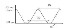
图3展示了调谐电路间的耦合如何随相对旋转位置的变化而改变。Figure 3 shows how the coupling between tuned circuits changes with relative rotational position.
图4展示了一个印刷电路板布局的例子,它可被用于两调谐电路中的任何一个。Figure 4 shows an example of a printed circuit board layout that can be used for either of the two tuned circuits.
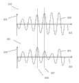
图5展示了在被激发的谐振电路中,震荡蓄积后的耦合效应。Figure 5 shows the coupling effect after accumulation of oscillations in an excited resonant circuit.
图6展示了一个可用于检测耦合变化的实例电路。Figure 6 shows an example circuit that can be used to detect changes in coupling.
图7展示了另一个可用于同样用途的实例电路。Figure 7 shows another example circuit that can be used for the same purpose.
图8展示了一个数字和模拟电路模块架构的例子,可用于单片机中来提供必要的驱动和传感能力。Figure 8 shows an example of a digital and analog circuit block architecture that can be used in a microcontroller to provide the necessary drive and sensing capabilities.
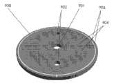
图9展示了一个可任意旋转的调谐电路板的视觉效果图。Figure 9 shows a visual representation of a tuning board that can be rotated arbitrarily.
图10展示了一个本身固定的调谐电路板的视觉效果图。Figure 10 shows a visual representation of the tuning board itself fixed.
图11展示了一些测试结果,以便在不同的距离和大小组合中达到最佳传感性能。Figure 11 shows some test results to achieve the best sensing performance in different distance and size combinations.
图1和2展示了两个物件1和2,他们间的相对旋转位置需要被感知。在这个例子中,物件1被假设是固定的,而物件2会绕着轴5为中心旋转。Figures 1 and 2 show two
斜线标识区域3,4,9和10为电感元件,他们在这个例子中大概是半圆形。
物件3和4串联在一起,并与电容6相连构成被驱动的谐振电路。物件9和10也类似的与电容11构成不被驱动的谐振电路。
两个谐振电路有很相似(但不一定相同)的共振频率。两者的共振频率足够接近,以至于当耦合时,一个电路中的谐振激发信号会引起另一个电路共振。Two resonant circuits have very similar (but not necessarily identical) resonant frequencies. The resonant frequencies of the two are close enough that when coupled, a resonant excitation signal in one circuit will cause the other to resonate.
一组电子器件12与基于物件3和4的谐振电路相连。这组器件有两个功能。它不仅提供激发共振的驱动信号,也检测震荡信号随时间变化的特征。A set of
物件3和4的连接和设计的原理如下:当电流通过3来产生一个方向的磁场,如箭头7所示,同样的电流流过串联的元件4则会产生一个感强相似但方向相反的磁场,如箭头8所示。电感器件9和10的连接设计原理也类似:在图1所示的旋转位置时,电感9内由于箭头7方向上的磁场增强产生的感应电磁力方向将与电感10内由于箭头8方向上的磁场增强产生的感应电磁力方向相叠加。因此图1中展示的旋转位置上,两调谐电路的实际耦合是最强的。The principle of the connection and design of
图2展示的是当部件2旋转过90度时的情况。这时由3中电流产生的电磁场只有一半穿过9,而另一半穿过10。而因3中电流变化而产生9和10内的电磁力此时方向相反,因此不会叠加,反而减少。类似的,4中电流产生的场会在9和10中激发方向不同的电磁力。所以在这个位置上谐振电路间的实际耦合为最小。在极端情况下,如果诸物件均对称,激发出的电磁力将会完全抵消,而导致的结果为实际耦合值为零。Figure 2 shows the situation when
图3以一种图形的形式展示了如图1和2所示的两个调谐电路之间的有效耦合是如何随着部件1和2的相对旋转而变化的。在这个图表中,纵坐标轴300代表两个调谐电路间的耦合角度,横坐标轴301表示两个部件间的旋转角。耦合度在最大值302 和最小值303之间循环变化。两个连续的最大耦合值之间的角度在图表中为90度,如线段304所示。两个连续的最小耦合值之间的角度也一样(如线段305所示)。Figure 3 shows in a graphical form how the effective coupling between two tuned circuits as shown in Figures 1 and 2 varies with the relative rotation of
图4以一种图形的形式展示了一种可能的印刷电路板布线,它可以形成一个恰当的反对称场模式,因此可作为一种实现感应部件3和4以及9和10的方案。它还说明了印刷电路布线如何让与电容器6(或11)连接以组成调谐电路。循环箭头400和401指示了循环电流的方向,由此可见目前的布线中电流会在两个半圆中流向相反的方向,导致两边产生的磁场方向也相反。Figure 4 shows a possible printed circuit board layout in a graphical form, which can form a suitable antisymmetric field pattern, so as a solution for realizing the
图5展示了两个示意图,它们以图形的形式说明了当施加一个接近电路共振频率的激励信号时,被驱动调谐电路里的振幅如何随着时间变化。在两图中纵坐标轴503都表示被驱动调谐电路两端的电压,而横坐标502都代表时间。图500中的波形504展表了当耦合很低甚至为零的情况。在这种情况下,振幅随着时间增长,最终稳定在一个固定的最大振幅。图501中的波形505展表了当耦合很高的情况。在这种情况下,最初振幅会增长但经过几个周期后又会降低。通过在恰当的时间点采样两电压波形,譬如506和507,并比较两电压值,耦合角度便可以被确定 – 在低耦合情况下,采样点507处的电压将高于采样点506处的电压,而在高耦合情况下则正好相反。两采样电压间变化的正负符号提供了一个明显可辨别高低耦合度间差异的手段,而两物件的相对位置也可由此推知。Figure 5 shows two diagrams that graphically illustrate how the amplitude in a driven tuned circuit varies with time when an excitation signal near the circuit's resonant frequency is applied. In both figures the axis of
图表6展示了一个可以执行必要辨别的电子装置简图。一个控制和序列元件600通过连接601提供一个激励信号到被驱动调谐电路602的一端,而电路的另一端则被连接到零伏电路节点612。箭头604指示被驱动调谐电路602和非被驱动调谐电路603之间的耦合变化角度。在被驱动调谐电路602两端产生的电压波形通过连接点605被传播到两个如模块606和607所示的采样和保持电路。控制和序列部件600分别产生控制信号610和611到这些电路,使得它们可以分别在图5中的506和507点采样这个波形。被保持的样本将进一步被比较器件608所对比,以在609出产生一个数字输出。Figure 6 shows a simplified diagram of an electronic device that can perform the necessary discrimination. A control and sequence element 600 provides an excitation signal via connection 601 to one end of a driven tuned circuit 602 , while the other end of the circuit is connected to zero volt circuit node 612 . Arrow 604 indicates the angle of coupling change between the driven tuned circuit 602 and the non-driven tuned circuit 603 . The voltage waveform developed across the driven tuned circuit 602 is propagated through connection point 605 to the two sample and hold circuits shown as blocks 606 and 607 . The control and sequence component 600 generates control signals 610 and 611 respectively to these circuits so that they can sample this waveform at
图表7展示了另外一个可以实现必要辨别功能的电子装置简图。一个控制和序列元件700通过连接701提供一个激励信号到被驱动调谐电路702的一端,而电路的另一端则被连接到零伏电路节点711。箭头704指示被驱动调谐电路702和非被驱动调谐电路703之间的耦合变化角度。在被驱动调谐电路702两端产生的电压波形通过连接点705和一个二极管706被传播到两个电容708和708。控制和序列部件700可以通过驱动闸门控制信号709来操作一个以场效应管710为例的开关。当信号709有效时,开关710提供一个低电阻路径到电路零电压点711,从而阻止电容708充电。序列器件700产生一个与电路702,703共振频率很接近的激发信号,以致在调谐电路两端产生一个如图5的震荡波形。此波形中的前几个周期里,无论704的耦合程度如何,振幅一直增加,序列器保持信号709有效,而在之后的几个周期里再输出使其无效。这意味着开关710将会在振荡的前几个周期被打开(低电阻),而随着振幅的增长每一次新的波峰都将对电容器707充电,使其达到一个新峰值电压(减去不可避免的二极管706两端电压降)。当控制信号709停止,开关710关闭时,下一步发生什么将取决于振幅是否继续增长亦或回落。如果波形持续增长如图500所示,那么每一个新的电压峰值(减去二极管706两端电压降)将会超过电容器707内由前一峰值留下的剩余电压,而使充电电流继续流动,积累一些电荷在电容器708里。另一方面,如果波形减退,新的电压峰值(减去二极管706两端电压降)将不会超过电容器707内的残留电压,也不会有充电电流,所以电容器708将保持放电。最终电容器708两端的电压值可以被直接用作一个输出信号712,来指示耦合度704的大小。或者,这个电压值相对于电路零伏节点711可以与一组固定电压参考值713进行比较,这要用到一个比较器714来得出一个数字输出715。Figure 7 shows another schematic diagram of an electronic device that can perform the necessary discrimination function. A control and
图表8展示了一个范例简图,其中包括模拟驱动和感应板块,以及数码驱动和感应板块,这些均可以在单片机硬件中实现并连接在其总线上(800)。总线允许单片机软件来设置和读取各系统模块的数据。单片机内部32千赫振荡器(801)输出到预换算器(802),将频率降低后再输出到一个定时器(803)。此定时器用于确定间歇性测量位置点的间隔。当被测量间隔定时器的脉冲输出信号触发后,快速时钟控制器(804)即启动快速时钟(805)。快速时钟被测量序列器(806)所使用,来控制产生驱动和采样信号,这些信号则驱动模拟驱动模块(807)和模拟感应模块(809)。这些均与单片机外部的谐振电路(808)互动。而产生的数字采样信号被正交解码器(810)处理以用来检测任一方向的旋转。正交解码器更新寄存器中的总计数器(812)和反向计数器(811)。它也会更新一个超速检测器(813),用于检测当旋转速率加快以至于需要更高的采样率来避免错过旋转圈数。当这种情况发生或者当任意一个计数器将要溢出时,一个单片机中断便会由中断生产控制器产生并移交给单片机内的中断控制器(815),使软件从计数寄存器中采集数据或者通过向间隔测量计时器中写入新数据来改变特性和提高采样率。在适当的时候单片机还可以设置校准寄存器(816)来改变快速时钟控制器(805)的性能,以使用快速时钟计数器(817)来累计出某已知数量的32千赫时钟周期内快速时钟的总数量。32KHz振荡器为晶振控制而因此精确。所以此机制允许单片机软件来计算快速时钟的周期并在必要时通过写入校准寄存器(816)来调节此周期。这使得软件可以确保由快速时钟生成的驱动信号能足够接近谐振电流的共振频率,尽管快速振荡器的具体性能会随使用时间和温度等参数而改变。
图表9 展示了一个探测器装置的可自由转动部分的视觉效果图。900展示了一个范例的电路板布线图。一个中心孔(901)或者固定孔(902)是用于把探测器的这个部分连接到旋转轴或者其他被检测的旋转物件上。共振频率可以通过选择适当的电容值(903)来设定。导通孔(904)被用于连接电路板另外一边的布线区域,既可以把不同区域间连接起来,又不干扰电板可见面导线的连通性。Figure 9 shows a visual representation of a freely rotating part of the detector assembly. 900 shows an example circuit board layout diagram. A central hole (901) or fixing hole (902) is used to attach this part of the detector to the rotating shaft or other rotating object to be detected. The resonant frequency can be set by choosing an appropriate capacitor value (903). The via hole (904) is used to connect the wiring area on the other side of the circuit board, which can connect different areas without interfering with the connectivity of the wires on the visible surface of the board.
图表10展示了探测器静态部分的视觉效果图。(1000)展示了一个范例的电路板布线图。(1001)展示了可用于设定和记录不同的旋转角位置的刻度线,这些会在确认系统正常运行时派上用场。固定孔(1002)帮助固定探测器的这部分。在这个实现装置里,在电路板不可见的另外一边还有另一个类似的电感布线。它与可见的那部分摆成45度角,以允许正交检测。在这个装置里,三极管(1004)用于选择在任一时候两布线中的哪一个会被会使用。电容器(1006)用于使电感元件共振。接头(1003)允许使用扁平柔性电缆来连接驱动控制和传感电路两部分。Figure 10 shows a visual rendering of the static part of the detector. (1000) shows an example board layout diagram. (1001) shows tick marks that can be used to set and record different rotational angle positions, these will come in handy when confirming proper operation of the system. Fixing holes (1002) help fix this part of the detector. In this implementation, there is another similar inductive trace on the other side of the board that is not visible. It is placed at a 45 degree angle to the visible part to allow for orthogonal detection. In this arrangement, a transistor (1004) is used to select which of the two wires will be used at any one time. A capacitor (1006) is used to resonate the inductive element. The connector (1003) allows the use of a flat flexible cable to connect the two parts of the drive control and sensing circuits.
在很多可行的应用中,诸如当把旋转信息从水量计潮湿的一面传递到干燥的一面,在旋转和固定部分之间会存在一些屏障或者其它的介入元件。尽量使探测器能够在两部分距离最宽的时候继续工作可以扩大本检测器的应用领域。通常来说,电感的布线面积越大,感应器可以工作的间隔距离就越大。另外还可以通过改变振幅采样点的位置来进一步提高间隔距离。图11标示了一个与图9和图10类似的检测装置中固定和旋转探测器间的最大工作距离。图表11展示了最大工作距离如何随电感布线直径和振幅采样点而改变的。1101展示了最大工作距离与电感布线直径大约成线型关系。在所有的测试案例中,最大工作间隔均超过D/3,其中D是电感布线区的直径。1102展示了在测试的不同方案中,不同的感应的时间会导致不同的性能。 第六个脉冲的情况下系统的性能比第四个和第五个脉冲的情形要更好,即使后者有更大面积的电感布线。In many possible applications, such as when transferring rotational information from the wet side of the meter to the dry side, there will be some barrier or other intervening element between the rotating and fixed parts. Trying to make the detector continue to work when the distance between the two parts is the widest can expand the application field of the detector. In general, the larger the inductor routing area, the greater the separation distance the inductor can operate. In addition, the separation distance can be further increased by changing the positions of the amplitude sampling points. Figure 11 shows the maximum working distance between the fixed and rotating detectors in a detection setup similar to that shown in Figures 9 and 10. Figure 11 shows how the maximum working distance varies with inductor trace diameter and amplitude sampling point. 1101 shows the approximately linear relationship between the maximum working distance and the diameter of the inductor wiring. In all test cases, the maximum working separation exceeds D/3, where D is the diameter of the inductor routing area. 1102 shows that different sensing times lead to different performance in different schemes tested. The performance of the system is better in the case of the sixth pulse than in the case of the fourth and fifth pulses, even though the latter has a larger area of inductive routing.
图表12展示了一张与图9和10类似的实际工作的范例装置照片。这包括了一个自由旋转部分(1202),在这个例子中它围绕一个中间轴(1203)自由旋转,和一个固定部分(1201)。
在此发明的实现方案中,流体的速度和方向都会被探测。图6和7展示了实现探测的可行电路范例。尽管图6和7分别展示了一个探测频道,通常会有两个探测频道,其中一个用于探测流速,另一个探测方向。尽管如此,仅仅使用一个探测频道也有可能同时探测流体的速度和方向。In an implementation of the invention, both the velocity and direction of the fluid are detected. Figures 6 and 7 show examples of possible circuits for probing. Although Figures 6 and 7 each show one detection channel, there are usually two detection channels, one for velocity and the other for direction. Nevertheless, it is possible to simultaneously detect the velocity and direction of the fluid using only one detection channel.
Claims (20)
Translated fromChineseApplications Claiming Priority (3)
| Application Number | Priority Date | Filing Date | Title |
|---|---|---|---|
| GB1006301.4 | 2010-04-15 | ||
| GB1006301.4AGB2482651B (en) | 2010-04-15 | 2010-04-15 | An electromagnetic method for sensing the relative position of two items using coupled tuned circuits |
| PCT/GB2011/050751WO2011128698A1 (en) | 2010-04-15 | 2011-04-15 | An electromagnetic method for sensing the relative position of two items using coupled tuned circuits |
Publications (2)
| Publication Number | Publication Date |
|---|---|
| CN102939516Atrue CN102939516A (en) | 2013-02-20 |
| CN102939516B CN102939516B (en) | 2016-03-02 |
Family
ID=42245259
Family Applications (1)
| Application Number | Title | Priority Date | Filing Date |
|---|---|---|---|
| CN201180029443.8AExpired - Fee RelatedCN102939516B (en) | 2010-04-15 | 2011-04-15 | Electromagnetic method for sensing relative position between two objects by using coupling tuning circuit |
Country Status (6)
| Country | Link |
|---|---|
| US (1) | US20130093436A1 (en) |
| EP (1) | EP2558822B1 (en) |
| JP (1) | JP2013524253A (en) |
| CN (1) | CN102939516B (en) |
| GB (1) | GB2482651B (en) |
| WO (1) | WO2011128698A1 (en) |
Cited By (2)
| Publication number | Priority date | Publication date | Assignee | Title |
|---|---|---|---|---|
| CN106248111A (en)* | 2015-06-11 | 2016-12-21 | 亚德诺半导体集团 | For determining the system of the position of loose impediment, circuit and method |
| CN108592781A (en)* | 2018-05-14 | 2018-09-28 | 同济大学 | A kind of motor rotor position detection method and detection device |
Families Citing this family (10)
| Publication number | Priority date | Publication date | Assignee | Title |
|---|---|---|---|---|
| GB2494183A (en)* | 2011-09-02 | 2013-03-06 | Sonuus Ltd | Musical effect controller with a position sensor comprising a tuned resonant circuit |
| GB201203685D0 (en)* | 2012-03-01 | 2012-04-18 | Elster Metering Ltd | Rotational position sensing |
| US9435830B2 (en)* | 2013-01-18 | 2016-09-06 | Cyberonics, Inc. | Implantable medical device depth estimation |
| DE102013102543B4 (en)* | 2013-03-13 | 2024-02-01 | Minebea Mitsumi Inc. | Rotary encoder with low power consumption |
| GB2569578B (en)* | 2017-12-20 | 2020-07-08 | Sonuus Ltd | Keyboard sensor systems and methods |
| GB2570533B (en) | 2017-12-20 | 2021-09-22 | Sonuus Ltd | Keyboard sensor systems and methods |
| GB2578346B (en) | 2018-08-07 | 2021-03-03 | Sonuus Ltd | Computer input devices |
| CN111657795B (en)* | 2020-06-17 | 2022-06-21 | 美智纵横科技有限责任公司 | Sweeper recharging system and method, sweeper and charging seat |
| GB2610369B (en)* | 2021-06-08 | 2025-02-19 | Sonuus Ltd | Position or movement sensing system |
| CN117706438B (en)* | 2023-08-01 | 2024-11-15 | 珅斯电子(上海)有限公司 | Variable magnetic sensor, magnetic field intensity measuring method and current detecting method |
Citations (6)
| Publication number | Priority date | Publication date | Assignee | Title |
|---|---|---|---|---|
| US4608564A (en)* | 1982-11-08 | 1986-08-26 | General Services Engineering, Inc. | Apparatus for the remote monitoring of meters and other devices |
| US4642786A (en)* | 1984-05-25 | 1987-02-10 | Position Orientation Systems, Ltd. | Method and apparatus for position and orientation measurement using a magnetic field and retransmission |
| CN1117577A (en)* | 1994-01-28 | 1996-02-28 | 三菱电机株式会社 | Absolute position detection apparatus and error compensation methods therefor |
| US20020140419A1 (en)* | 2000-07-31 | 2002-10-03 | Denis Duret | Short-distance positioning system |
| CN1973177A (en)* | 2004-01-16 | 2007-05-30 | 诺米克斯股份有限公司 | Distance measuring device |
| CN101035462A (en)* | 2004-09-01 | 2007-09-12 | 皇家飞利浦电子股份有限公司 | Magnetic resonance marker based position and orientation probe |
Family Cites Families (7)
| Publication number | Priority date | Publication date | Assignee | Title |
|---|---|---|---|---|
| US3355667A (en)* | 1965-12-16 | 1967-11-28 | Collins Radio Co | Automatically tuned coupled resonant circuits |
| DE1810387A1 (en)* | 1968-11-22 | 1970-06-11 | Bergwerksverband Gmbh | Monitoring device for conveyor belts |
| US3852662A (en)* | 1971-03-19 | 1974-12-03 | B Katz | Proximity measuring employing a self-balancing bridge and measuring the adjustable balancing component thereof |
| GB9309073D0 (en)* | 1993-05-01 | 1993-06-16 | Dames Andrew N | Resonator orientation sensing |
| EP1455454A3 (en)* | 2003-03-07 | 2009-09-30 | Pilz Auslandsbeteiligungen GmbH | Inductive monitoring device and method for monitoring the distance between a first and a second coil |
| GB0813226D0 (en)* | 2008-07-18 | 2008-08-27 | Univ Gent | Resonance-based rotor position estimation in salient machines |
| JP4961510B2 (en)* | 2010-02-18 | 2012-06-27 | オリンパスメディカルシステムズ株式会社 | Position detection system and method of operating position detection system |
- 2010
- 2010-04-15GBGB1006301.4Apatent/GB2482651B/ennot_activeExpired - Fee Related
- 2011
- 2011-04-15EPEP11719048.8Apatent/EP2558822B1/ennot_activeNot-in-force
- 2011-04-15CNCN201180029443.8Apatent/CN102939516B/ennot_activeExpired - Fee Related
- 2011-04-15WOPCT/GB2011/050751patent/WO2011128698A1/enactiveApplication Filing
- 2011-04-15JPJP2013504345Apatent/JP2013524253A/ennot_activeWithdrawn
- 2012
- 2012-10-15USUS13/651,821patent/US20130093436A1/ennot_activeAbandoned
Patent Citations (6)
| Publication number | Priority date | Publication date | Assignee | Title |
|---|---|---|---|---|
| US4608564A (en)* | 1982-11-08 | 1986-08-26 | General Services Engineering, Inc. | Apparatus for the remote monitoring of meters and other devices |
| US4642786A (en)* | 1984-05-25 | 1987-02-10 | Position Orientation Systems, Ltd. | Method and apparatus for position and orientation measurement using a magnetic field and retransmission |
| CN1117577A (en)* | 1994-01-28 | 1996-02-28 | 三菱电机株式会社 | Absolute position detection apparatus and error compensation methods therefor |
| US20020140419A1 (en)* | 2000-07-31 | 2002-10-03 | Denis Duret | Short-distance positioning system |
| CN1973177A (en)* | 2004-01-16 | 2007-05-30 | 诺米克斯股份有限公司 | Distance measuring device |
| CN101035462A (en)* | 2004-09-01 | 2007-09-12 | 皇家飞利浦电子股份有限公司 | Magnetic resonance marker based position and orientation probe |
Cited By (5)
| Publication number | Priority date | Publication date | Assignee | Title |
|---|---|---|---|---|
| CN106248111A (en)* | 2015-06-11 | 2016-12-21 | 亚德诺半导体集团 | For determining the system of the position of loose impediment, circuit and method |
| CN106248111B (en)* | 2015-06-11 | 2020-01-10 | 亚德诺半导体集团 | System, circuit and method for determining the position of a movable object |
| US10551215B2 (en) | 2015-06-11 | 2020-02-04 | Analog Devices Global Unlimited Company | Systems, circuits and methods for determining a position of a movable object |
| CN108592781A (en)* | 2018-05-14 | 2018-09-28 | 同济大学 | A kind of motor rotor position detection method and detection device |
| CN108592781B (en)* | 2018-05-14 | 2021-05-11 | 同济大学 | A kind of motor rotor position detection method and detection device |
Also Published As
| Publication number | Publication date |
|---|---|
| CN102939516B (en) | 2016-03-02 |
| WO2011128698A1 (en) | 2011-10-20 |
| EP2558822B1 (en) | 2015-09-16 |
| JP2013524253A (en) | 2013-06-17 |
| EP2558822A1 (en) | 2013-02-20 |
| GB2482651A (en) | 2012-02-15 |
| US20130093436A1 (en) | 2013-04-18 |
| GB2482651B (en) | 2013-05-01 |
| GB201006301D0 (en) | 2010-06-02 |
Similar Documents
| Publication | Publication Date | Title |
|---|---|---|
| CN102939516B (en) | Electromagnetic method for sensing relative position between two objects by using coupling tuning circuit | |
| JP6276190B2 (en) | Magnetic field sensor | |
| CN100594360C (en) | Displacement detection system | |
| CN100535603C (en) | Angular position inductive sensor | |
| CN109883456A (en) | A magnetoresistive inertial sensor chip | |
| CN105369412B (en) | A kind of spinning frame burn out detection sensing device of adaptive measuring distance | |
| JP3190704B2 (en) | Device for detecting rotation of rotating element | |
| JP2011059130A (en) | Position detector | |
| US10254355B2 (en) | Magnetic sensor including a Lorentz force transducer driven at a frequency different from the resonance frequency, and method for driving a Lorentz force transducer | |
| CN102246006B (en) | Circuit system and method for evaluating sensors | |
| CN101871801B (en) | Intelligent flow meter adopting TMR (Tele Meter Reading) magnetic sensor | |
| CN103245819A (en) | Method for measuring direct current or direct voltage by adopting magnetic excitation resonant piezoresistive cantilever beam | |
| CN109655771A (en) | Ac magnetic susceptibility measuring device and its measurement method | |
| CN107576336B (en) | Non-magnetic sensor | |
| JP2012122780A (en) | Rotational angle detecting device | |
| US20140290365A1 (en) | Mems device | |
| CN207908659U (en) | The device of periodic modulation Magnetic Sensor sensitivity decrease device noise | |
| CN109029593A (en) | Turbine flowmeter and flow rate testing methods | |
| CN104596605B (en) | A magnetic automatic flow recorder | |
| CN113804284A (en) | Vibration displacement measuring method of vibration type viscoelastic sensor | |
| CN106093457B (en) | Rotating speed sensor | |
| JP2000338257A (en) | Magnetic metal sensor | |
| CN114623888A (en) | Measurement detection system, measurement method thereof and measurement meter | |
| JPH11183195A (en) | Magnetic metal sensor and magnetic metal detecting method | |
| CN103899299B (en) | A device for measuring the angular position of a drilling tool in a rotating state |
Legal Events
| Date | Code | Title | Description |
|---|---|---|---|
| C06 | Publication | ||
| PB01 | Publication | ||
| C10 | Entry into substantive examination | ||
| SE01 | Entry into force of request for substantive examination | ||
| C14 | Grant of patent or utility model | ||
| GR01 | Patent grant | ||
| CF01 | Termination of patent right due to non-payment of annual fee | Granted publication date:20160302 Termination date:20170415 | |
| CF01 | Termination of patent right due to non-payment of annual fee |