CN102927191A - Coil internally-installed type magnetorheological damper with oil needle - Google Patents
Coil internally-installed type magnetorheological damper with oil needleDownload PDFInfo
- Publication number
- CN102927191A CN102927191ACN2012104113584ACN201210411358ACN102927191ACN 102927191 ACN102927191 ACN 102927191ACN 2012104113584 ACN2012104113584 ACN 2012104113584ACN 201210411358 ACN201210411358 ACN 201210411358ACN 102927191 ACN102927191 ACN 102927191A
- Authority
- CN
- China
- Prior art keywords
- piston rod
- shock absorber
- coil
- magneto
- end cover
- Prior art date
- Legal status (The legal status is an assumption and is not a legal conclusion. Google has not performed a legal analysis and makes no representation as to the accuracy of the status listed.)
- Pending
Links
Images


Landscapes
- Fluid-Damping Devices (AREA)
- Vibration Prevention Devices (AREA)
Abstract
Translated fromChinese
Description
Translated fromChinese技术领域technical field
本发明属于机械振动控制技术领域,特别是涉及一种带油针的线圈内置式磁流变减震器。The invention belongs to the technical field of mechanical vibration control, in particular to a magneto-rheological shock absorber with oil needles and built-in coils.
背景技术Background technique
磁流变减震器是一种新型智能减震器,其可以通过控制电流的大小来控制输出的阻尼力,从而达到半主动控制的效果,因此已在建筑、桥梁、汽车和飞机等多个领域得到了广泛的应用,而且较一般减震器而言,磁流变减震器的响应速度快、阻尼力连续可调、结构简单、控制效果更好,因此应用前景良好。其工作原理是以磁流变液这种新型的智能材料作为减震器的工作液,并在安装于活塞杆的导磁套上缠绕线圈,线圈产生的磁场作用于磁流变液,通过控制电磁线圈中电流的大小来改变磁流变体的粘度,以达到阻尼力连续可调的目的。The magneto-rheological shock absorber is a new type of intelligent shock absorber, which can control the output damping force by controlling the magnitude of the current, so as to achieve the effect of semi-active control. Therefore, it has been widely used in buildings, bridges, automobiles and aircraft It has been widely used in the field, and compared with general shock absorbers, magnetorheological shock absorbers have fast response speed, continuously adjustable damping force, simple structure and better control effect, so they have good application prospects. Its working principle uses magnetorheological fluid, a new type of intelligent material, as the working fluid of the shock absorber, and a coil is wound on the magnetic sleeve installed on the piston rod. The magnetic field generated by the coil acts on the magnetorheological fluid, and through the control The magnitude of the current in the electromagnetic coil changes the viscosity of the magnetorheological fluid, so as to achieve the purpose of continuously adjustable damping force.
在现有的磁流变减震器中,基本都是仅通过电流来控制输出的阻尼力,但是由于导磁材料具有一定的磁饱和度,当电流达到某个值时,导磁材料会因为磁饱和而使作用于磁流变液的磁感应强度不会有明显的变化,此时阻尼力将不会随着电流的增加而有所增加,因此在冲击载荷较大、结构大小受限等情况下仅仅通过控制电流来改变阻尼力的大小是不能达到很好的控制效果的。另外,在线圈内置式磁流变减震器中,线圈的密封往往不能得到很好的解决,而一旦线圈与磁流变液有接触,线圈外层的漆包线就有可能因受到腐蚀而引起漏电、断线等故障,这样将会使电流控制失去作用。In the existing magneto-rheological shock absorbers, the output damping force is basically only controlled by current, but because the magnetically permeable material has a certain degree of magnetic saturation, when the current reaches a certain value, the magnetically permeable material will be Due to magnetic saturation, the magnetic induction intensity acting on the magnetorheological fluid will not change significantly. At this time, the damping force will not increase with the increase of current. Therefore, in the case of large impact load and limited structure size, etc. It is impossible to achieve a good control effect only by controlling the current to change the magnitude of the damping force. In addition, in the magnetorheological shock absorber with built-in coil, the sealing of the coil is often not well resolved, and once the coil is in contact with the magnetorheological fluid, the enameled wire on the outer layer of the coil may be corroded and cause leakage , disconnection and other faults, this will make the current control lose its effect.
发明内容Contents of the invention
为了解决上述问题,本发明的目的在于提供一种能够同时实现电流控制和行程控制、阻尼力变化范围大、密封性好、结构简单可靠的带油针的线圈内置式磁流变减震器。In order to solve the above problems, the object of the present invention is to provide a coil built-in magneto-rheological shock absorber with oil needles, which can realize current control and stroke control at the same time, has a wide range of damping force variation, good sealing performance, and simple and reliable structure.
为了达到上述目的,本发明提供的带油针的线圈内置式磁流变减震器包括缸筒、上端盖、下端盖、活塞杆、节流盘、导向盘、活塞和锥形变截面油针;其中缸筒的上下两端分别安装有上端盖和下端盖,并且上端盖上安装有一个单向阀;活塞杆、节流盘、导向盘和活塞组装在一起后以能够沿缸筒轴向移动的方式设置在缸筒的内部,并且缸筒下部内部注有磁流变液,上部充有高压氮气;活塞杆的上端部内部形成有一个上部轴向中心孔,并且上端部圆周面上交错形成有多个与上部轴向中心孔相连通的径向孔,下端部内部形成有一个下部轴向中心孔,并且下端部延伸至下端盖的外部;导向盘呈圆环状,套装在活塞杆的上端圆周面上,并且其外径与缸筒的内径相同;节流盘也呈圆环状,安装在活塞杆顶面上,并且节流盘中心处的节流孔与活塞杆的上部轴向中心孔位于同一条直线;活塞由上导磁盘、下导磁盘、密封套件、导磁套和导磁线圈组成,其中上导磁盘和下导磁盘均呈环状,两者相隔距离套装在活塞杆中部的圆周面上,并且上导磁盘的下端面边缘和下导磁盘的上端面边缘沿轴向向外突出形成一边沿;导磁套也呈环状,套装在位于上导磁盘和下导磁盘之间的活塞杆上;导磁线圈缠绕在导磁套上,并且导线末端经下部轴向中心孔引至减震器外部;密封套件设置在导磁线圈的外圆周面上,并且其外部两端分别与上导磁盘和下导磁盘上的边沿相接触;锥形变截面油针的底面安装在上端盖的底面中部,下端对准活塞杆的上部轴向中心孔。In order to achieve the above purpose, the coil built-in magneto-rheological shock absorber with oil needle provided by the present invention includes a cylinder, an upper end cover, a lower end cover, a piston rod, a throttle plate, a guide plate, a piston, and a tapered variable-section oil needle; The upper and lower ends of the cylinder are respectively equipped with an upper end cover and a lower end cover, and a check valve is installed on the upper end cover; the piston rod, the throttle plate, the guide plate and the piston are assembled together to move axially along the cylinder. The way is set inside the cylinder, and the lower part of the cylinder is filled with magnetorheological fluid, and the upper part is filled with high-pressure nitrogen; the upper end of the piston rod is formed with an upper axial center hole, and the upper end of the circumferential surface is staggered to form There are multiple radial holes connected with the upper axial center hole, and a lower axial center hole is formed inside the lower end, and the lower end extends to the outside of the lower end cover; the guide plate is in the shape of a ring, and is sleeved on the piston rod On the upper circumferential surface, and its outer diameter is the same as the inner diameter of the cylinder; the throttle plate is also in the shape of a ring, installed on the top surface of the piston rod, and the throttle hole at the center of the throttle plate is axially aligned with the upper part of the piston rod The central hole is located on the same straight line; the piston is composed of an upper guide disk, a lower guide disk, a sealing kit, a magnetic sleeve and a magnetic coil, in which the upper guide disk and the lower guide disk are ring-shaped, and the two are set on the piston rod with a distance On the circumferential surface of the middle part, and the edge of the lower end surface of the upper guide disk and the edge of the upper end surface of the lower guide disk protrude outward in the axial direction to form an edge; between the piston rod; the magnetic coil is wound on the magnetic sleeve, and the end of the wire is led to the outside of the shock absorber through the lower axial center hole; the sealing set is arranged on the outer circumferential surface of the magnetic coil, and its outer two The ends are in contact with the edges of the upper guide disc and the lower guide disc respectively; the bottom surface of the tapered oil needle with variable cross-section is installed in the middle of the bottom surface of the upper end cover, and the lower end is aligned with the upper axial center hole of the piston rod.
所述的密封套件包括密封套、两个O形胶圈和两个橡胶垫圈,其中密封套呈环形,并且中部部位的外径大于两端外径,套装在导磁线圈的外圆周面上,其上两端部位的外表面上分别凹陷形成有一个环形密封槽;每个环形密封槽内装有一个O形胶圈,同时密封套中部两端位置分别安装有一个橡胶垫圈。The sealing kit includes a sealing sleeve, two O-shaped rubber rings and two rubber washers, wherein the sealing sleeve is ring-shaped, and the outer diameter of the middle part is larger than the outer diameter of both ends, and is set on the outer circumferential surface of the magnetic conduction coil. An annular sealing groove is respectively recessed on the outer surface of the upper two ends; each annular sealing groove is equipped with an O-shaped rubber ring, and at the same time, a rubber gasket is respectively installed at the two ends of the middle part of the sealing sleeve.
所述的上导磁盘和下导磁盘的外圆周面上形成有多条环形阻尼槽,并且上导磁盘和下导磁盘最大外径处与缸筒内表面之间的距离为1mm。A plurality of annular damping grooves are formed on the outer circumferential surfaces of the upper guide disk and the lower guide disk, and the distance between the maximum outer diameter of the upper guide disk and the lower guide disk and the inner surface of the cylinder is 1mm.
所述的活塞杆上径向孔11的数量为8个。The number of
所述的上端盖和下端盖通过多根双头螺栓与缸筒1相互连接。The upper end cover and the lower end cover are connected to each other with the
本发明提供的带油针的线圈内置式磁流变减震器具有如下优点:The coil built-in magneto-rheological shock absorber with oil needle provided by the present invention has the following advantages:
1、本减震器在一般磁流变减震器基础上增设了锥形变截面油针,可利用锥形变截面油针与节流孔的配合作为行程控制部件来实现行程控制,提高了阻尼力变化范围、乘坐舒适性和减震效果。1. This shock absorber is based on the general magneto-rheological shock absorber with a conical variable cross-section oil needle, which can be used as a stroke control component to achieve stroke control by using the conical variable cross-section oil needle and the throttle hole, which improves the damping force. Variation range, ride comfort and shock absorption.
2、一旦电流控制磁流变液体粘度失效,上述行程控制部件仍然可以改变不同行程时的阻尼力大小,较一般磁流变减震器更为安全可靠。2. Once the viscosity of the magneto-rheological fluid controlled by the current fails, the above-mentioned stroke control part can still change the damping force at different strokes, which is safer and more reliable than ordinary magnetorheological shock absorbers.
3、密封部分采用O形胶圈和橡胶垫圈的双密封结构,大大增加了对导磁线圈的保护,避免了磁流变液对导磁线圈的侵蚀,使活塞密封性能大大提高。3. The sealing part adopts a double-seal structure of O-shaped rubber ring and rubber gasket, which greatly increases the protection of the magnetic coil, avoids the erosion of the magnetic coil by the magneto-rheological fluid, and greatly improves the sealing performance of the piston.
4、本减震器在体积补偿方面没有使用蓄能器,而是采用直接充高压氮气的方式,因此结构更加简单。4. The shock absorber does not use an accumulator for volume compensation, but directly fills it with high-pressure nitrogen, so the structure is simpler.
附图说明Description of drawings
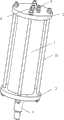
图1为本发明提供的带油针的线圈内置式磁流变减震器外部结构立体图。Fig. 1 is a perspective view of the external structure of the magneto-rheological shock absorber with built-in coils provided by the present invention.
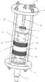
图2为去除缸筒后本发明提供的带油针的线圈内置式磁流变减震器结构立体图。Fig. 2 is a perspective view of the structure of the built-in coil magneto-rheological shock absorber with oil needle provided by the present invention after the cylinder is removed.
图3为本发明提供的带油针的线圈内置式磁流变减震器中密封套件装配示意图。Fig. 3 is a schematic diagram of the assembly of the seal kit in the coil built-in magneto-rheological shock absorber with oil needle provided by the present invention.
图4为本发明提供的带油针的线圈内置式磁流变减震器中活塞及活塞杆装配示意图。Fig. 4 is a schematic diagram of the assembly of the piston and the piston rod in the magneto-rheological shock absorber with an oil needle inside the coil provided by the present invention.
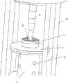
图5为本发明提供的带油针的线圈内置式磁流变减震器中行程控制部件外部结构放大图。Fig. 5 is an enlarged view of the external structure of the stroke control part in the coil built-in magneto-rheological shock absorber with oil needle provided by the present invention.
图6为本发明提供的带油针的线圈内置式磁流变减震器中磁路结构示意图。Fig. 6 is a schematic diagram of the magnetic circuit structure in the coil built-in magneto-rheological shock absorber with oil needles provided by the present invention.
具体实施方式Detailed ways
下面结合附图和具体实施例对本发明提供的带油针的线圈内置式磁流变减震器进行详细说明。The coil built-in magneto-rheological shock absorber with oil needles provided by the present invention will be described in detail below with reference to the accompanying drawings and specific embodiments.
如图1-图6所示,本发明提供的带油针的线圈内置式磁流变减震器包括缸筒1、上端盖2、下端盖3、活塞杆4、节流盘5、导向盘6、活塞7和锥形变截面油针8;其中缸筒1的上下两端分别安装有上端盖2和下端盖3,并且上端盖2上安装有一个单向阀9;活塞杆4、节流盘5、导向盘6和活塞7组装在一起后以能够沿缸筒1轴向移动的方式设置在缸筒1的内部,并且缸筒1下部内部注有磁流变液,上部充有高压氮气;活塞杆4的上端部内部形成有一个上部轴向中心孔10,并且上端部圆周面上交错形成有多个与上部轴向中心孔10相连通的径向孔11,下端部内部形成有一个下部轴向中心孔12,并且下端部延伸至下端盖3的外部;导向盘6呈圆环状,套装在活塞杆4的上端圆周面上,并且其外径与缸筒1的内径相同;节流盘5也呈圆环状,安装在活塞杆4顶面上,并且节流盘5中心处的节流孔23与活塞杆4的上部轴向中心孔10位于同一条直线;活塞7由上导磁盘13、下导磁盘14、密封套件、导磁套24和导磁线圈16组成,其中上导磁盘13和下导磁盘14均呈环状,两者相隔距离套装在活塞杆4中部的圆周面上,并且上导磁盘13的下端面边缘和下导磁盘14的上端面边缘沿轴向向外突出形成一边沿17;导磁套24也呈环状,套装在位于上导磁盘13和下导磁盘14之间的活塞杆4上;导磁线圈16缠绕在导磁套24上,并且导线末端经下部轴向中心孔12引至减震器外部;密封套件设置在导磁线圈16的外圆周面上,并且其外部两端分别与上导磁盘13和下导磁盘14上的边沿17相接触;锥形变截面油针8的底面安装在上端盖2的底面中部,下端对准活塞杆4的上部轴向中心孔10。As shown in Fig. 1-Fig. 6, the magneto-rheological shock absorber with built-in coil with oil needle provided by the present invention includes a
所述的密封套件包括密封套15、两个O形胶圈19和两个橡胶垫圈20,其中密封套15呈环形,并且中部部位的外径大于两端外径,套装在导磁线圈16的外圆周面上,其上两端部位的外表面上分别凹陷形成有一个环形密封槽21;每个环形密封槽21内装有一个O形胶圈19,同时密封套15中部两端位置分别安装有一个橡胶垫圈20。The sealing kit includes a
所述的上导磁盘13和下导磁盘14的外圆周面上形成有多条环形阻尼槽18,并且上导磁盘13和下导磁盘14最大外径处与缸筒1内表面之间的距离为1mm。A plurality of
所述的活塞杆4上径向孔11的数量为8个。The number of
所述的上端盖2和下端盖3通过多根双头螺栓22与缸筒1相互连接。The
现将本发明提供的带油针的线圈内置式磁流变减震器组装方法阐述如下:The assembly method of the built-in coil magneto-rheological shock absorber with oil needle provided by the present invention is described as follows:
1、首先在密封套15上的每个环形密封槽21内安装一个O形胶圈19,同时在密封套15中部两端位置分别安装一个橡胶垫圈20,由此组装好密封套件;1. First install an O-
2、将导向盘6套装在活塞杆4的上端圆周面上,然后将节流盘5用螺钉安装在活塞杆4的顶面上;2. Set the
3、将上导磁盘13、缠有导磁线圈16的导磁套24以及密封套件和下导磁盘14依次安装在活塞杆4中部外圆周面上,并在下导磁盘14下部用螺母预紧固定,由此在活塞杆4上组装好活塞7;3. Install the
4、将单向阀9安装在上端盖2上,然后将上端盖2安装在缸筒1上端,之后将上述安装在一起的活塞杆4和活塞7装入缸筒1内部;4. Install the one-
5、在缸筒1的下端安装好下端盖3,并用多根双头螺栓22将上端盖2和下端盖3拉紧;5. Install the
6、通过图中未示出的注油孔向缸筒1下部注入磁流变液至预定容量,然后将注油孔密封住;6. Inject magnetorheological fluid into the lower part of the
7、通过单向阀9向缸筒1的上部充入规定压强的高压氮气,至此装配完成。7. Fill the upper part of the
现将本发明提供的带油针的线圈内置式磁流变减震器工作原理阐述如下:使用本发明提供的带油针的线圈内置式磁流变减震器前,将其上的活塞杆3下端连接在飞机或汽车的轮胎结构上,上端盖2通过相应部件连接重物。在使用过程中,当飞机或汽车的轮胎受到震动而推动本带油针的线圈内置式磁流变减震器上的活塞杆4向上移动时,缸筒1下部的磁流变液将通过活塞杆4上的径向孔11流入上部轴向中心孔10及节流盘5上的节流孔23内,由活塞杆4移动而引起的缸筒1体积的变化由高压氮气体积的变化来补偿。在缓冲初期,由于冲击载荷较大,需要较大的节流孔23面积,因此锥形变截面油针8位于节流孔23的外部;而在缓冲末期,随着活塞杆4的上移,锥形变截面油针5的下端也随之压入节流盘5上的节流孔23内,从而使节流孔23的面积变小,这时就能够提供较大的阻尼力。即,随着活塞杆4行程的变化,通过节流孔23的磁流变液的流量也随之变化,节流孔23处的阻尼力也会随着行程的变化而变化,从而实现行程控制。可利用调节节流孔23的大小来调节阻尼力的大小。与此同时,在缓冲过程中,给导磁线圈16中施加电流后,则主磁路将会按图6中虚线所示的路径分布,这时位于活塞7和缸筒1之间环形间隙中磁流变液的粘度将会随着电流大小的变化而变化,从而实现电流控制。可通过改变导磁线圈16电流大小的方式来改变位于活塞7和缸筒1之间环形间隙中磁流变液的磁感应强度大小,从而调节阻尼力的大小。The working principle of the built-in coil magneto-rheological shock absorber with oil needle provided by the present invention is described as follows: Before using the coil built-in magneto-rheological shock absorber with oil needle provided by the present invention, the piston rod on it 3. The lower end is connected to the tire structure of an airplane or an automobile, and the
Claims (5)
Translated fromChinesePriority Applications (1)
| Application Number | Priority Date | Filing Date | Title |
|---|---|---|---|
| CN2012104113584ACN102927191A (en) | 2012-10-25 | 2012-10-25 | Coil internally-installed type magnetorheological damper with oil needle |
Applications Claiming Priority (1)
| Application Number | Priority Date | Filing Date | Title |
|---|---|---|---|
| CN2012104113584ACN102927191A (en) | 2012-10-25 | 2012-10-25 | Coil internally-installed type magnetorheological damper with oil needle |
Publications (1)
| Publication Number | Publication Date |
|---|---|
| CN102927191Atrue CN102927191A (en) | 2013-02-13 |
Family
ID=47642075
Family Applications (1)
| Application Number | Title | Priority Date | Filing Date |
|---|---|---|---|
| CN2012104113584APendingCN102927191A (en) | 2012-10-25 | 2012-10-25 | Coil internally-installed type magnetorheological damper with oil needle |
Country Status (1)
| Country | Link |
|---|---|
| CN (1) | CN102927191A (en) |
Cited By (6)
| Publication number | Priority date | Publication date | Assignee | Title |
|---|---|---|---|---|
| CN104455178A (en)* | 2014-12-11 | 2015-03-25 | 中国民航大学 | Damping-adjustable magneto-rheological lag damper |
| CN105387120A (en)* | 2015-11-26 | 2016-03-09 | 中国民航大学 | Single-actuating type magneto-rheological shock absorber used for aircraft landing gear |
| CN107489725A (en)* | 2017-08-20 | 2017-12-19 | 郑州大学 | A kind of MRE vibration absorbers suitable for broadband excitation |
| CN107505557A (en)* | 2017-08-03 | 2017-12-22 | 中南大学 | Flexible loading test device for microelectronic component |
| CN110319139A (en)* | 2019-06-05 | 2019-10-11 | 西安理工大学 | A kind of machine tool feed direction vibration absorber |
| CN117686319A (en)* | 2024-02-02 | 2024-03-12 | 江苏英达机械有限公司 | Shot blasting strength detection device |
Citations (6)
| Publication number | Priority date | Publication date | Assignee | Title |
|---|---|---|---|---|
| US3990687A (en)* | 1976-02-05 | 1976-11-09 | Curnutt Charles R | Shock absorber with controlled fluid bypass means |
| JPS596446A (en)* | 1982-07-02 | 1984-01-13 | Showa Mfg Co Ltd | Damping force adjustment device in hydraulic shock absorber |
| CN1351554A (en)* | 1999-04-22 | 2002-05-29 | 克劳斯·莱本 | Tension/compression buffers for trailers on rail and wheeled vehicles |
| JP2002168282A (en)* | 2000-11-28 | 2002-06-14 | Showa Corp | Hydraulic shock absorber |
| CN2739412Y (en)* | 2004-10-29 | 2005-11-09 | 中国民用航空学院 | Gap sealed throttling channel damper |
| CN201723641U (en)* | 2010-08-06 | 2011-01-26 | 长春工程学院 | Novel magnetorheological fluid shock absorber |
- 2012
- 2012-10-25CNCN2012104113584Apatent/CN102927191A/enactivePending
Patent Citations (6)
| Publication number | Priority date | Publication date | Assignee | Title |
|---|---|---|---|---|
| US3990687A (en)* | 1976-02-05 | 1976-11-09 | Curnutt Charles R | Shock absorber with controlled fluid bypass means |
| JPS596446A (en)* | 1982-07-02 | 1984-01-13 | Showa Mfg Co Ltd | Damping force adjustment device in hydraulic shock absorber |
| CN1351554A (en)* | 1999-04-22 | 2002-05-29 | 克劳斯·莱本 | Tension/compression buffers for trailers on rail and wheeled vehicles |
| JP2002168282A (en)* | 2000-11-28 | 2002-06-14 | Showa Corp | Hydraulic shock absorber |
| CN2739412Y (en)* | 2004-10-29 | 2005-11-09 | 中国民用航空学院 | Gap sealed throttling channel damper |
| CN201723641U (en)* | 2010-08-06 | 2011-01-26 | 长春工程学院 | Novel magnetorheological fluid shock absorber |
Cited By (10)
| Publication number | Priority date | Publication date | Assignee | Title |
|---|---|---|---|---|
| CN104455178A (en)* | 2014-12-11 | 2015-03-25 | 中国民航大学 | Damping-adjustable magneto-rheological lag damper |
| CN104455178B (en)* | 2014-12-11 | 2016-06-01 | 中国民航大学 | A kind of damp adjustable magnetorheological shimmy damper |
| CN105387120A (en)* | 2015-11-26 | 2016-03-09 | 中国民航大学 | Single-actuating type magneto-rheological shock absorber used for aircraft landing gear |
| CN105387120B (en)* | 2015-11-26 | 2017-10-10 | 中国民航大学 | A kind of nonoculture dynamic formula MR vibration damper for undercarriage |
| CN107505557A (en)* | 2017-08-03 | 2017-12-22 | 中南大学 | Flexible loading test device for microelectronic component |
| CN107505557B (en)* | 2017-08-03 | 2024-09-24 | 中南大学 | Flexible loading test device for microelectronic devices |
| CN107489725A (en)* | 2017-08-20 | 2017-12-19 | 郑州大学 | A kind of MRE vibration absorbers suitable for broadband excitation |
| CN110319139A (en)* | 2019-06-05 | 2019-10-11 | 西安理工大学 | A kind of machine tool feed direction vibration absorber |
| CN117686319A (en)* | 2024-02-02 | 2024-03-12 | 江苏英达机械有限公司 | Shot blasting strength detection device |
| CN117686319B (en)* | 2024-02-02 | 2024-04-12 | 江苏英达机械有限公司 | Shot blasting strength detection device |
Similar Documents
| Publication | Publication Date | Title |
|---|---|---|
| CN102121509B (en) | Magnetorheological damper with annular and disc-shaped liquid flow resistance channels simultaneously | |
| CN104696420B (en) | frequency-sensitive shock absorber | |
| CN105736624B (en) | Magneto-rheological damper with unidirectional damping property | |
| CN102927191A (en) | Coil internally-installed type magnetorheological damper with oil needle | |
| US9086111B2 (en) | Valve assembly of shock absorber | |
| CN102913587B (en) | Magneto-rheological damper | |
| CN110778636A (en) | Bidirectional independently controllable magnetorheological damper | |
| CN103534508B (en) | Magneto-rheological damping assembly | |
| CN201875043U (en) | Slide-valve-type magnetorheological shock absorber | |
| CN103470674B (en) | A kind of Inner-channel vehicle suspension system magnetorheological damper | |
| CN101382177A (en) | Dual-channel magnetorheological damper with channel gating capability | |
| WO2021104185A1 (en) | Self-sensing separated dual-cylinder magnetorheological damper | |
| CN105864346A (en) | Piston valve of magnetorheological fluid damper and magnetorheological fluid damper | |
| CN108331876B (en) | A shock absorber damping regulating valve | |
| CN103352956A (en) | Magneto-rheological damper with asymmetrical controllable damping characteristic | |
| CN105240444B (en) | Magneto-rheological vibration damper based on parallel-connection structure | |
| CN101319698A (en) | Magnetorheological Damper with Adjustable Damping | |
| CN206802174U (en) | Vehicle suspension Novel magneto-rheological damper with bypass fluid course | |
| CN108757815A (en) | The big adjustable damping range magneto-rheological vibration damper that annular gap and dish type gap combine | |
| CN103758913A (en) | Mixed mode magneto-rheological shock absorber | |
| CN104963986A (en) | Magneto-rheological damper with mixed flow type fluid flowing channel | |
| CN102287472A (en) | Series single-cylinder magnet-rheological hydro-pneumatic spring | |
| CN104373500B (en) | External many circular holes damp channel MR damper | |
| CN108980258B (en) | A magnetorheological damping regulating valve | |
| CN202733123U (en) | Magnetorheological flow control valve |
Legal Events
| Date | Code | Title | Description |
|---|---|---|---|
| C06 | Publication | ||
| PB01 | Publication | ||
| C10 | Entry into substantive examination | ||
| SE01 | Entry into force of request for substantive examination | ||
| C02 | Deemed withdrawal of patent application after publication (patent law 2001) | ||
| WD01 | Invention patent application deemed withdrawn after publication | Application publication date:20130213 |