CN102918476A - Controllers for interfacing with computing programs using position, orientation, or motion - Google Patents
Controllers for interfacing with computing programs using position, orientation, or motionDownload PDFInfo
- Publication number
- CN102918476A CN102918476ACN2010800631263ACN201080063126ACN102918476ACN 102918476 ACN102918476 ACN 102918476ACN 2010800631263 ACN2010800631263 ACN 2010800631263ACN 201080063126 ACN201080063126 ACN 201080063126ACN 102918476 ACN102918476 ACN 102918476A
- Authority
- CN
- China
- Prior art keywords
- display
- controller
- image
- captured
- controller device
- Prior art date
- Legal status (The legal status is an assumption and is not a legal conclusion. Google has not performed a legal analysis and makes no representation as to the accuracy of the status listed.)
- Granted
Links
Images


Classifications
- G—PHYSICS
- G06—COMPUTING OR CALCULATING; COUNTING
- G06F—ELECTRIC DIGITAL DATA PROCESSING
- G06F3/00—Input arrangements for transferring data to be processed into a form capable of being handled by the computer; Output arrangements for transferring data from processing unit to output unit, e.g. interface arrangements
- G06F3/01—Input arrangements or combined input and output arrangements for interaction between user and computer
- G06F3/03—Arrangements for converting the position or the displacement of a member into a coded form
- G06F3/0304—Detection arrangements using opto-electronic means
- G06F3/0317—Detection arrangements using opto-electronic means in co-operation with a patterned surface, e.g. absolute position or relative movement detection for an optical mouse or pen positioned with respect to a coded surface
- A—HUMAN NECESSITIES
- A63—SPORTS; GAMES; AMUSEMENTS
- A63F—CARD, BOARD, OR ROULETTE GAMES; INDOOR GAMES USING SMALL MOVING PLAYING BODIES; VIDEO GAMES; GAMES NOT OTHERWISE PROVIDED FOR
- A63F13/00—Video games, i.e. games using an electronically generated display having two or more dimensions
- A63F13/20—Input arrangements for video game devices
- A63F13/21—Input arrangements for video game devices characterised by their sensors, purposes or types
- A63F13/211—Input arrangements for video game devices characterised by their sensors, purposes or types using inertial sensors, e.g. accelerometers or gyroscopes
- A—HUMAN NECESSITIES
- A63—SPORTS; GAMES; AMUSEMENTS
- A63F—CARD, BOARD, OR ROULETTE GAMES; INDOOR GAMES USING SMALL MOVING PLAYING BODIES; VIDEO GAMES; GAMES NOT OTHERWISE PROVIDED FOR
- A63F13/00—Video games, i.e. games using an electronically generated display having two or more dimensions
- A63F13/20—Input arrangements for video game devices
- A63F13/21—Input arrangements for video game devices characterised by their sensors, purposes or types
- A63F13/213—Input arrangements for video game devices characterised by their sensors, purposes or types comprising photodetecting means, e.g. cameras, photodiodes or infrared cells
- A—HUMAN NECESSITIES
- A63—SPORTS; GAMES; AMUSEMENTS
- A63F—CARD, BOARD, OR ROULETTE GAMES; INDOOR GAMES USING SMALL MOVING PLAYING BODIES; VIDEO GAMES; GAMES NOT OTHERWISE PROVIDED FOR
- A63F13/00—Video games, i.e. games using an electronically generated display having two or more dimensions
- A63F13/20—Input arrangements for video game devices
- A63F13/21—Input arrangements for video game devices characterised by their sensors, purposes or types
- A63F13/214—Input arrangements for video game devices characterised by their sensors, purposes or types for locating contacts on a surface, e.g. floor mats or touch pads
- A—HUMAN NECESSITIES
- A63—SPORTS; GAMES; AMUSEMENTS
- A63F—CARD, BOARD, OR ROULETTE GAMES; INDOOR GAMES USING SMALL MOVING PLAYING BODIES; VIDEO GAMES; GAMES NOT OTHERWISE PROVIDED FOR
- A63F13/00—Video games, i.e. games using an electronically generated display having two or more dimensions
- A63F13/20—Input arrangements for video game devices
- A63F13/21—Input arrangements for video game devices characterised by their sensors, purposes or types
- A63F13/218—Input arrangements for video game devices characterised by their sensors, purposes or types using pressure sensors, e.g. generating a signal proportional to the pressure applied by the player
- A—HUMAN NECESSITIES
- A63—SPORTS; GAMES; AMUSEMENTS
- A63F—CARD, BOARD, OR ROULETTE GAMES; INDOOR GAMES USING SMALL MOVING PLAYING BODIES; VIDEO GAMES; GAMES NOT OTHERWISE PROVIDED FOR
- A63F13/00—Video games, i.e. games using an electronically generated display having two or more dimensions
- A63F13/25—Output arrangements for video game devices
- A63F13/28—Output arrangements for video game devices responding to control signals received from the game device for affecting ambient conditions, e.g. for vibrating players' seats, activating scent dispensers or affecting temperature or light
- A63F13/285—Generating tactile feedback signals via the game input device, e.g. force feedback
- A—HUMAN NECESSITIES
- A63—SPORTS; GAMES; AMUSEMENTS
- A63F—CARD, BOARD, OR ROULETTE GAMES; INDOOR GAMES USING SMALL MOVING PLAYING BODIES; VIDEO GAMES; GAMES NOT OTHERWISE PROVIDED FOR
- A63F13/00—Video games, i.e. games using an electronically generated display having two or more dimensions
- A63F13/40—Processing input control signals of video game devices, e.g. signals generated by the player or derived from the environment
- A63F13/42—Processing input control signals of video game devices, e.g. signals generated by the player or derived from the environment by mapping the input signals into game commands, e.g. mapping the displacement of a stylus on a touch screen to the steering angle of a virtual vehicle
- A63F13/428—Processing input control signals of video game devices, e.g. signals generated by the player or derived from the environment by mapping the input signals into game commands, e.g. mapping the displacement of a stylus on a touch screen to the steering angle of a virtual vehicle involving motion or position input signals, e.g. signals representing the rotation of an input controller or a player's arm motions sensed by accelerometers or gyroscopes
- A—HUMAN NECESSITIES
- A63—SPORTS; GAMES; AMUSEMENTS
- A63F—CARD, BOARD, OR ROULETTE GAMES; INDOOR GAMES USING SMALL MOVING PLAYING BODIES; VIDEO GAMES; GAMES NOT OTHERWISE PROVIDED FOR
- A63F13/00—Video games, i.e. games using an electronically generated display having two or more dimensions
- A63F13/80—Special adaptations for executing a specific game genre or game mode
- A63F13/843—Special adaptations for executing a specific game genre or game mode involving concurrently two or more players on the same game device, e.g. requiring the use of a plurality of controllers or of a specific view of game data for each player
- G—PHYSICS
- G06—COMPUTING OR CALCULATING; COUNTING
- G06F—ELECTRIC DIGITAL DATA PROCESSING
- G06F3/00—Input arrangements for transferring data to be processed into a form capable of being handled by the computer; Output arrangements for transferring data from processing unit to output unit, e.g. interface arrangements
- G06F3/01—Input arrangements or combined input and output arrangements for interaction between user and computer
- G06F3/017—Gesture based interaction, e.g. based on a set of recognized hand gestures
- G—PHYSICS
- G06—COMPUTING OR CALCULATING; COUNTING
- G06F—ELECTRIC DIGITAL DATA PROCESSING
- G06F3/00—Input arrangements for transferring data to be processed into a form capable of being handled by the computer; Output arrangements for transferring data from processing unit to output unit, e.g. interface arrangements
- G06F3/01—Input arrangements or combined input and output arrangements for interaction between user and computer
- G06F3/03—Arrangements for converting the position or the displacement of a member into a coded form
- G06F3/0304—Detection arrangements using opto-electronic means
- G06F3/0325—Detection arrangements using opto-electronic means using a plurality of light emitters or reflectors or a plurality of detectors forming a reference frame from which to derive the orientation of the object, e.g. by triangulation or on the basis of reference deformation in the picked up image
- G—PHYSICS
- G06—COMPUTING OR CALCULATING; COUNTING
- G06F—ELECTRIC DIGITAL DATA PROCESSING
- G06F3/00—Input arrangements for transferring data to be processed into a form capable of being handled by the computer; Output arrangements for transferring data from processing unit to output unit, e.g. interface arrangements
- G06F3/01—Input arrangements or combined input and output arrangements for interaction between user and computer
- G06F3/03—Arrangements for converting the position or the displacement of a member into a coded form
- G06F3/033—Pointing devices displaced or positioned by the user, e.g. mice, trackballs, pens or joysticks; Accessories therefor
- G06F3/0346—Pointing devices displaced or positioned by the user, e.g. mice, trackballs, pens or joysticks; Accessories therefor with detection of the device orientation or free movement in a 3D space, e.g. 3D mice, 6-DOF [six degrees of freedom] pointers using gyroscopes, accelerometers or tilt-sensors
- A—HUMAN NECESSITIES
- A63—SPORTS; GAMES; AMUSEMENTS
- A63F—CARD, BOARD, OR ROULETTE GAMES; INDOOR GAMES USING SMALL MOVING PLAYING BODIES; VIDEO GAMES; GAMES NOT OTHERWISE PROVIDED FOR
- A63F13/00—Video games, i.e. games using an electronically generated display having two or more dimensions
- A63F13/20—Input arrangements for video game devices
- A63F13/21—Input arrangements for video game devices characterised by their sensors, purposes or types
- A63F13/215—Input arrangements for video game devices characterised by their sensors, purposes or types comprising means for detecting acoustic signals, e.g. using a microphone
- A—HUMAN NECESSITIES
- A63—SPORTS; GAMES; AMUSEMENTS
- A63F—CARD, BOARD, OR ROULETTE GAMES; INDOOR GAMES USING SMALL MOVING PLAYING BODIES; VIDEO GAMES; GAMES NOT OTHERWISE PROVIDED FOR
- A63F2300/00—Features of games using an electronically generated display having two or more dimensions, e.g. on a television screen, showing representations related to the game
- A63F2300/50—Features of games using an electronically generated display having two or more dimensions, e.g. on a television screen, showing representations related to the game characterized by details of game servers
- A63F2300/53—Features of games using an electronically generated display having two or more dimensions, e.g. on a television screen, showing representations related to the game characterized by details of game servers details of basic data processing
- A63F2300/538—Features of games using an electronically generated display having two or more dimensions, e.g. on a television screen, showing representations related to the game characterized by details of game servers details of basic data processing for performing operations on behalf of the game client, e.g. rendering
Landscapes
- Engineering & Computer Science (AREA)
- Multimedia (AREA)
- Human Computer Interaction (AREA)
- General Engineering & Computer Science (AREA)
- Theoretical Computer Science (AREA)
- Physics & Mathematics (AREA)
- General Physics & Mathematics (AREA)
- User Interface Of Digital Computer (AREA)
- Controls And Circuits For Display Device (AREA)
- Projection Apparatus (AREA)
- Length Measuring Devices By Optical Means (AREA)
Abstract
Description
Translated fromChinese技术领域technical field
本发明涉及用于将控制装置与计算装置相接口的方法和系统,以及更具体地,涉及用于将控制装置与在基础计算装置执行的计算程序相接口的方法和系统。The present invention relates to methods and systems for interfacing a control device with a computing device, and more particularly, to a method and system for interfacing a control device with a computing program executing on a base computing device.
背景技术Background technique
视频游戏工业这些年已经发生了很多变化。随着计算能力的扩展,视频游戏的开发人员同样已经编制出利用这些增加的计算能力的游戏软件。为此,视频游戏开发人员一直在编写结合复杂操作和数学运算的游戏,以产生非常逼真的游戏体验。The video game industry has changed a lot over the years. As computing power has expanded, developers of video games have also programmed game software to take advantage of these increased computing power. To this end, video game developers have been writing games that incorporate complex manipulation and mathematical operations to produce a very realistic gaming experience.
示例的游戏平台可以是索尼索尼

电脑游戏产业的一个发展趋势是开发增加用户和游戏系统之间的互动的游戏。一种实现更丰富的互动体验的方法是通过使用无线游戏控制器(其运动由游戏系统跟踪)以跟踪玩家的运动并使用这些运动作为游戏的输入。总的来说,姿势输入指具有诸如计算系统、视频游戏控制台、智能设备等的电子装置对由玩家做出的且由电子装置捕获的某种姿势做出反应。A growing trend in the computer gaming industry is to develop games that increase the interaction between the user and the gaming system. One way to achieve a richer interactive experience is by using a wireless game controller (whose movement is tracked by the game system) to track the player's movements and use those movements as input for the game. In general, gesture input refers to having an electronic device such as a computing system, video game console, smart device, etc. react to a certain gesture made by a player and captured by the electronic device.
在这种情况下产生本发明的实施例。In this case an embodiment of the invention results.
发明内容Contents of the invention
本发明的实施例提供用于将控制装置与在基础计算装置执行的计算机程序相接口的方法和系统。应该理解本发明可以以多种途径实现,例如过程、设备、系统、装置或者计算机可读介质上的方法。以下描述本发明的一些创新性实施例。Embodiments of the present invention provide methods and systems for interfacing a control device with a computer program executing on a base computing device. It should be understood that the present invention can be implemented in various ways, such as a process, an apparatus, a system, an apparatus, or a method on a computer readable medium. Some innovative embodiments of the invention are described below.
在一个实施例中,在基于计算机的具有显示器和用于与交互程序相接口的控制器装置的系统中,提供用于确定所述控制器装置的位置的方法。根据该方法,所述基于计算机的系统被初始化以建立所述控制器装置相对于所述显示器的起始位置。该初始化的方法操作包括:(i)使用集成在所述控制器装置中的摄像头来捕获所述显示器的图像;(ii)捕获由所述控制器装置投射的辐射图案的图像;以及(iii)分析所述被捕获的显示器的图像和由所述控制器装置投射的辐射图案的图像来确定在通过所投射的辐射图案的图像确定的所述控制器装置的距离处被捕获的图像中显示器的大小。In one embodiment, in a computer based system having a display and a controller device for interfacing with an interactive program, a method for determining the position of the controller device is provided. According to the method, the computer-based system is initialized to establish a starting position of the controller device relative to the display. The initializing method operations include: (i) capturing an image of the display using a camera integrated in the controller device; (ii) capturing an image of the radiation pattern projected by the controller device; and (iii) analyzing the captured image of the display and the image of the radiation pattern projected by the controller device to determine the position of the display in the captured image at the distance of the controller device determined by the projected image of the radiation pattern size.
进一步根据所述用于确定位置的方法,在所述控制器装置处捕获连续的所述显示器的图像。然后根据所述被捕获的连续的显示器的图像中显示器的透视畸变确定所述控制器装置相对于所述显示器的位置。向所述基于计算机的系统提供所确定的所述控制器的位置以与所述交互程序相接口从而引发所述交互程序的动作。In further accordance with the method for determining position, successive images of the display are captured at the controller device. The position of the controller means relative to the display is then determined from the perspective distortion of the display in the captured successive images of the display. The determined position of the controller is provided to the computer-based system for interfacing with the interactive program to cause actions of the interactive program.
在一个实施例中,根据在所述被捕获的显示器图像中的显示器的位置和方向确定所述控制器装置的方向。在一个实施例中,所述控制器装置的方向从由俯仰、翻滚和偏航组成的组中选择。In one embodiment, the orientation of the controller device is determined from the position and orientation of the display in the captured image of the display. In one embodiment, the orientation of said controller means is selected from the group consisting of pitch, roll and yaw.
在一个实施例中,通过跟踪每个连续图像被捕获时所述控制器的位置确定所述控制器装置的动作。In one embodiment, the action of the controller means is determined by tracking the position of the controller when each successive image is captured.
在一个实施例中,由所述控制器投射的辐射图案是由红外投影仪产生的。In one embodiment, the radiation pattern projected by the controller is generated by an infrared projector.
在一个实施例中,当所述控制器装置的位置不能根据所述被捕获的连续的显示器的图像所确定,那么执行辅助位置确定。首先,从所述控制器装置投射辐射图案。然后,在所述控制器装置处捕获连续的所述辐射图案的图像。并且,根据所述被捕获的连续的辐射图案的图像估算所述控制器装置的位置。In one embodiment, when the position of the controller device cannot be determined from the captured continuous display images, then an auxiliary position determination is performed. First, a radiation pattern is projected from the controller device. Successive images of said radiation pattern are then captured at said controller device. And, estimating the position of the controller device from the captured images of the continuous radiation pattern.
在一个实施例中,捕获所述显示器的图像的操作包括捕获足以能够确定所述显示器大小的所述显示器的一部分的图像。In one embodiment, capturing an image of the display includes capturing an image of a portion of the display sufficient to enable a size determination of the display.
在一个实施例中,捕获连续的所述显示器的图像的操作包括捕获足以能够确定所述控制器装置位置的连续的所述显示器的一部分的图像。In one embodiment, capturing images of a continuum of said displays comprises capturing images of a portion of said displays of a continuum sufficient to enable the position of said controller device to be determined.
根据本发明另一个实施例,在基于计算机的具有显示器和用于与交互程序相接口的控制器装置的系统中,提供用于确定所述控制器装置的位置的方法。首先,接收由所述基于计算机的系统的用户输入的所述显示器的尺寸。然后,在所述控制器装置捕获连续的所述显示器的图像。根据所述显示器的尺寸和所述被捕获的连续的显示器的图像中显示器的透视畸变确定所述控制器装置相对于所述显示器的位置。然后,向基于计算机的系统提供所确定的所述控制器的位置以与所述交互程序相接口从而引发所述交互程序的动作。According to another embodiment of the present invention, in a computer based system having a display and a controller device for interfacing with an interactive program, a method for determining the position of said controller device is provided. First, a size of the display is received as input by a user of the computer-based system. Successive images of the display are then captured at the controller device. The position of the controller means relative to the display is determined from the size of the display and the perspective distortion of the display in the captured continuous images of the display. The determined position of the controller is then provided to a computer-based system to interface with the interactive program to cause action of the interactive program.
在一个实施例中,所述显示器的尺寸包括所述显示器的高宽比和所述显示器的对角线测量。In one embodiment, the dimensions of the display include an aspect ratio of the display and a diagonal measurement of the display.
根据本发明的另一个实施例,提供用于与交互程序相接口的系统。所述系统包括用于显示所述交互程序的显示器。提供用于与所述交互程序相接口的控制器装置。所述控制器装置包括用于投射辐射图案的投影仪、用于捕获被投射的辐射图案的图像的第一摄像头,和用于捕获所述显示器的图像的第二摄像头。提供用于初始化所述系统来建立所述控制器装置相对于所述显示器的起始位置的初始化逻辑。所述初始化逻辑被配置为:(i)使用所述第二摄像头捕获所述显示器的图像;(ii)使用所述第一摄像头捕获由所述投影仪投射的辐射图案的图像;以及(iii)分析所述被捕获的显示器图像和所述辐射图案的图像来确定在通过所投射的辐射图案的图像确定的所述控制器装置的距离处被捕获的图像中所述显示器的大小。提供用于确定所述控制器装置相对于所述显示器的位置的位置确定逻辑。所述位置确定逻辑被配置为:(i)使用所述第二摄像头在所述控制器装置处捕获连续的所述显示器的图像;以及(ii)根据所述被捕获的连续的显示器的图像中所述显示器的透视畸变来确定所述控制器装置相对于所述显示器的位置。通信逻辑向基于计算机的系统提供所确定的所述控制器的位置以与所述交互程序相接口。According to another embodiment of the present invention, a system for interfacing with an interactive program is provided. The system includes a display for displaying the interactive program. Controller means are provided for interfacing with the interactive program. The controller arrangement includes a projector for projecting a radiation pattern, a first camera for capturing an image of the projected radiation pattern, and a second camera for capturing an image of the display. Initialization logic is provided for initializing the system to establish a home position of the controller device relative to the display. The initialization logic is configured to: (i) capture an image of the display using the second camera; (ii) capture an image of a radiation pattern projected by the projector using the first camera; and (iii) The captured image of the display and the image of the radiation pattern are analyzed to determine a size of the display in the captured image at a distance of the controller device determined by the projected image of the radiation pattern. Position determination logic is provided for determining a position of the controller device relative to the display. The location determination logic is configured to: (i) capture successive images of the display at the controller device using the second camera; The perspective distortion of the display is used to determine the position of the controller device relative to the display. Communications logic provides the determined location of the controller to a computer-based system for interfacing with the interactive program.
在一个实施例中,提供用于根据所述被捕获的连续的显示器的图像中所述显示器的位置和方向来确定所述控制器装置的方向的方向确定逻辑。在一个实施例中,所述控制器装置的方向从由俯仰、翻滚和偏航组成的组中选择。In one embodiment, orientation determination logic is provided for determining the orientation of the controller device from the position and orientation of the display in the captured continuous images of the display. In one embodiment, the orientation of said controller means is selected from the group consisting of pitch, roll and yaw.
在一个实施例中,提供用于通过跟踪每个连续图像被捕获时所述控制器的位置来确定所述控制器装置的动作的动作确定逻辑。In one embodiment, motion determination logic is provided for determining the motion of the controller means by tracking the position of the controller as each successive image is captured.
在一个实施例中,辅助位置确定逻辑被配置为当所述控制器装置的位置不能根据所述被捕获的连续的显示器的图像来确定时执行如下操作:(1)从所述控制器装置投射辐射图案;(2)在所述控制器装置处捕获连续的所述辐射图案的图像;以及(3)根据所述被捕获的连续的辐射图案的图像估算所述控制器装置的位置。In one embodiment, the auxiliary position determination logic is configured to perform the following operations when the position of the controller device cannot be determined from the captured continuous display images: (1) project a location from the controller device a radiation pattern; (2) capturing at the controller device a succession of images of the radiation pattern; and (3) estimating the position of the controller device from the captured images of the succession of radiation patterns.
在一个实施例中,捕获所述显示器的图像包括捕获足以能够确定所述显示器的大小的所述显示器的一部分的图像。In one embodiment, capturing an image of the display includes capturing an image of a portion of the display sufficient to enable a size determination of the display.
在一个实施例中,捕获连续的所述显示器的图像包括捕获足以能够确定所述控制器装置的位置的连续的所述显示器的一部分的图像。In one embodiment, capturing images of a continuum of said displays comprises capturing images of a portion of said displays of a continuum sufficient to enable determination of the position of said controller device.
通过示例的方式说明本发明的原理并结合附图,本发明的其它方面通过如下详细描述将变得清楚。Other aspects of the invention will become apparent from the following detailed description, illustrating by way of example the principles of the invention and taken in conjunction with the accompanying drawings.
附图说明Description of drawings
通过参考结合附图的以下描述可以理解本发明,其中:The present invention can be understood by reference to the following description taken in conjunction with the accompanying drawings, in which:
图1示出了根据本发明的实施例的通用交互系统;Fig. 1 shows a general interactive system according to an embodiment of the present invention;
图2示出了根据本发明的实施例的示例性控制器装置;Figure 2 shows an exemplary controller arrangement according to an embodiment of the present invention;
图3示出了根据本发明的实施例的动作捕获子组件的详细视图;Figure 3 shows a detailed view of a motion capture subassembly according to an embodiment of the invention;
图4A示出了根据本发明的实施例,具有向表面发出有图案的辐射光束的红外投影仪的控制器;Figure 4A illustrates a controller with an infrared projector emitting a patterned beam of radiation onto a surface, according to an embodiment of the invention;
图4B示出了根据本发明的实施例,由正在照射表面的控制器产生的圆锥形图案辐射光束的截面图;Figure 4B shows a cross-sectional view of a conically patterned radiation beam produced by a controller that is illuminating a surface, in accordance with an embodiment of the present invention;
图4C示出了根据本发明的实施例,与表面的垂直线偏离角度θ的辐射光束;Figure 4C illustrates a radiation beam offset by an angle θ from the normal to the surface, in accordance with an embodiment of the invention;
图4D示出了根据本发明的实施例,以与图4C所示辐射光束类似配置的辐射光束,其中控制器已被旋转90度;Figure 4D shows a radiation beam configured similarly to that shown in Figure 4C, where the controller has been rotated 90 degrees, in accordance with an embodiment of the invention;
图4E示出了发出具有三角形图案横截面形状的红外光束的控制器;Figure 4E shows a controller emitting an infrared beam having a triangular pattern cross-sectional shape;
图5示出了根据本发明的实施例,用于输入显示器尺寸的用户接口;FIG. 5 shows a user interface for inputting a display size according to an embodiment of the present invention;
图6A示出了根据本发明的实施例,用于帮助检测显示器外框的图案的示例;FIG. 6A shows an example of a pattern used to help detect a display frame according to an embodiment of the present invention;
图6B示出了根据本发明的实施例,用于帮助检测显示器外框的图案的示例;FIG. 6B shows an example of a pattern used to help detect a display frame according to an embodiment of the present invention;
图7A示出了根据本发明的实施例的位于显示器的正面的控制器,使得显示器出现在由控制器的RGB摄像头拍摄的被捕获的图像中;Figure 7A shows a controller positioned on the front of a display such that the display appears in a captured image taken by the controller's RGB camera, according to an embodiment of the present invention;
图7B示出了根据本发明的实施例的移到接近显示器的控制器,使得显示器在控制器处捕获的图像中看上去更大;FIG. 7B shows a controller moved closer to a display, making the display appear larger in an image captured at the controller, according to an embodiment of the invention;
图7C示出了根据本发明的实施例的移到显示器左侧的控制器,使得如在控制器处拍摄的被捕获图像中所见的显示器的图像显现透视畸变,该透视畸变由控制器的位置所导致;7C shows the controller moved to the left of the display, such that the image of the display, as seen in the captured image taken at the controller, exhibits perspective distortion determined by the controller's caused by the location;
图7D示出了根据本发明的实施例的控制器的俯视图,其中控制器的偏航已被负向转动;Figure 7D shows a top view of a controller in which the yaw of the controller has been turned negatively, according to an embodiment of the invention;
图7E示出了根据本发明的实施例的控制器的俯视图,其中控制器的翻滚已被正向调整;Figure 7E shows a top view of a controller in which the roll of the controller has been positively adjusted, according to an embodiment of the invention;
图7F示出了根据本发明的实施例的控制器的侧视图,其中控制器的俯仰已被正向转动;Figure 7F shows a side view of a controller according to an embodiment of the invention, wherein the pitch of the controller has been rotated positively;
图8A示出了根据本发明的实施例的显示器,其中一组跟踪条栅被呈现在显示器屏幕的边缘;Figure 8A shows a display in which a set of tracking bars are presented at the edge of the display screen, according to an embodiment of the present invention;
图8B示出了根据本发明的实施例的显示器,其中反射标签附着到角部;Figure 8B shows a display according to an embodiment of the invention with reflective labels attached to the corners;
图9A示出了根据本发明的实施例,附带具有重叠视野范围的多个RGB摄像头的控制器;Figure 9A shows a controller with multiple RGB cameras with overlapping fields of view, according to an embodiment of the present invention;
图9B示出了根据本发明的实施例,附带具有重叠视野范围的多个RGB摄像头的控制器;Figure 9B shows a controller with multiple RGB cameras with overlapping fields of view, according to an embodiment of the present invention;
图10A示出了根据本发明的实施例,具有配备鱼眼透镜的RGB摄像头的控制器;Figure 10A shows a controller with an RGB camera equipped with a fisheye lens, according to an embodiment of the present invention;
图10B示出了根据本发明的实施例,具有多个配备鱼眼透镜的RGB摄像头的控制器;Figure 10B shows a controller with multiple RGB cameras equipped with fisheye lenses, according to an embodiment of the present invention;
图11示出了根据本发明的实施例,在不同位置和方向的控制器的功能;Figure 11 shows the functions of the controller in different positions and orientations according to an embodiment of the present invention;
图12A示出了根据本发明的实施例的朝向显示器的控制器;Figure 12A shows a controller towards a display according to an embodiment of the present invention;
图12B示出了根据本发明的实施例的方向偏离显示器的控制器,使得控制器的红外功能被启动;Figure 12B shows a controller oriented away from a display such that the infrared function of the controller is activated, according to an embodiment of the present invention;
图12C示出了根据本发明的实施例的方向背离显示器的控制器;Figure 12C shows a controller oriented away from the display, according to an embodiment of the invention;
图13示出了根据本发明的实施例,在不同位置和方向持有控制器的用户;Figure 13 shows a user holding a controller in different positions and orientations according to an embodiment of the present invention;
图14示出了根据本发明的实施例,用于向交互程序提供控制器输入的系统的示意图;Fig. 14 shows a schematic diagram of a system for providing controller input to an interactive program according to an embodiment of the present invention;
图15示出了根据本发明的实施例,具有扩展连接器的控制器手柄的组件;Figure 15 shows an assembly of a controller handle with an expansion connector, according to an embodiment of the present invention;
图16示出了根据本发明的实施例,具有用于改善动作捕获的传感器的控制器;Figure 16 shows a controller with sensors for improved motion capture, according to an embodiment of the invention;
图17A示出了根据本发明的实施例的控制器手柄的配件;Figure 17A shows the fitting of a controller handle according to an embodiment of the present invention;
图17B示出了其中图17A的配件被连接到图15的控制器的一个实施例;Figure 17B shows an embodiment in which the accessory of Figure 17A is connected to the controller of Figure 15;
图18示出了根据本发明的实施例,可用于确定控制器位置的硬件和用户接口;Figure 18 illustrates hardware and user interfaces that may be used to determine the position of a controller, according to an embodiment of the present invention;
图19示出根据本发明的实施例,可用于处理指令的额外硬件;Figure 19 illustrates additional hardware that may be used to process instructions according to an embodiment of the present invention;
图20示出了根据本发明的实施例,同时支持多个用户的基于服务器的游戏-计算系统;Figure 20 illustrates a server-based gaming-computing system supporting multiple users simultaneously, according to an embodiment of the present invention;
图21A示出了根据本发明的实施例,用于初始化动作控制器来确定TV显示器大小的方法;Figure 21A illustrates a method for initializing a motion controller to determine the size of a TV display, according to an embodiment of the present invention;
图21B示出了根据本发明的实施例,用于使用RGB摄像头运行时跟踪TV显示器外框的方法;FIG. 21B shows a method for tracking the frame of a TV display at runtime using an RGB camera according to an embodiment of the present invention;
图22示出了根据本发明的实施例,使用激光距离测量来校准TV显示器物理大小的方法;22 illustrates a method of calibrating the physical size of a TV display using laser distance measurement, according to an embodiment of the present invention;
图23示出了根据本发明的实施例,用于提供与交互程序进行交互的方法。Fig. 23 shows a method for providing interaction with an interactive program according to an embodiment of the present invention.
具体实施方式Detailed ways
下面的实施例描述通过使用用户反馈和计算机程序的用户输入的视觉提示,将控制装置与在基础计算装置上执行的计算机程序相接口的方法和设备。The following embodiments describe methods and apparatus for interfacing a control device with a computer program executing on a base computing device by using user feedback and visual cues of user input for the computer program.
然而,本领域的普通技术人员应该清楚,本发明不使用这些特定细节的一些或者全部也可以实现。在其他情况下,并未详细说明众所周知的处理操作,目的是为了避免不必要地模糊本发明。It will be apparent, however, to one of ordinary skill in the art, that the present invention may be practiced without some or all of these specific details. In other instances, well known process operations have not been described in detail in order to avoid unnecessarily obscuring the present invention.
对图像分析所做的参考贯穿本发明的各种示例性实施例的详细描述,用于确定图像中的物体或物体的性能。此类分析可利用本领域中公知的各种图像识别方法和技术,而不会背离本发明的精神和范围。Reference is made throughout the detailed description of various exemplary embodiments of the invention to image analysis for determining objects or properties of objects in images. Such analysis may utilize various image recognition methods and techniques known in the art without departing from the spirit and scope of the present invention.
图1示出了通用交互系统101。该系统包括计算机103和显示器106。在各种实施例中,计算机103可以是通用计算机、专用计算机、游戏控制台,或其他诸如此类的装置,该装置执行呈现在显示器106上的交互程序。本领域公知的游戏控制台的例子包括由Sony、Microsoft、Nintendo等制造的那些游戏控制台。显示器106可以是电视、监视器、投影显示器,或能够从计算机103接收和呈现视频输出的其他这样的显示器和显示系统。用户102通过移动控制器100向交互程序提供输入。在一个优选的实施例中,控制器100与计算机103无线通信,因为比起有线连接,这种方式为控制器的运动提供了更多自由。FIG. 1 shows a
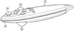
图2示出示例性的控制器100。所示的控制器100被设计为由用户102所持有。包括多个按钮202用于向交互程序提供输入。按钮202的特定功能由交互程序确定,且每个按钮202根据交互程序的规范可以或不可以由用户102配置或者由用户102指定。触发按钮203和操纵杆204提供额外的直观机制(intuitive mechanism)用于生成用户输入。尽管所示的控制器100设计成手持型,本发明的其他实施例中,控制器可以设计为以其他形式供用户102操纵。例如,控制器100可通过本领域公知的方式(诸如搭扣带或挽具状带子)附接到用户102。或者控制器100可被安装到物体上或表现为物体的形式,该物体可在用户102的控制下移动。例如,控制器100可以是方向盘组件的部分、类似乐器的装置,或可以展示运动用以向交互程序提供输入的其他装置或组件。此外,控制器100包括动作捕获子组件206,其包括专用于确定控制器100的位置和动作的多个硬件部件。FIG. 2 shows an
本领域的普通技术人员应理解,术语动作捕获、动作控制器等的使用应作广义的解释。动作捕获可包括在具体时间点对位置和方向的捕获,以及随时间推移对位置和方向的变化的捕获。位置通常参考三维空间(例如由x、y、z坐标表示)中的定位来描述。方向通常从俯仰(pitch)、偏航(yaw)和翻滚(roll)的方面来描述。Those of ordinary skill in the art will appreciate that the use of the terms motion capture, motion controller, etc. should be interpreted broadly. Motion capture may include the capture of position and orientation at a specific point in time, as well as the capture of changes in position and orientation over time. A location is typically described with reference to a position in three-dimensional space (eg, represented by x, y, z coordinates). Orientation is usually described in terms of pitch, yaw, and roll.
图3示出了动作捕获子组件206的详细视图。包括红外(IR)投影仪208来产生红外或近红外辐射光束219。该红外投影仪208包括发出红外或近红外光谱中的辐射的红外LED。在一个实施例中,红外LED210被放置在反射管212的一端。红外LED发出的辐射被控制在反射管212中。在反射管212的另一端提供孔214以允许辐射从反射管212漏出,使得穿过孔214的辐射大体集中于单个方向。在一个实施例中,该辐射接着穿过红外截止滤光器216,该红外截止滤光器216阻挡辐射的选择性部分从而形成图案。(在一个实施例中,该滤光器216也可称为红外通过(IR-PASS)滤光器,其作为物理快门(shutter)运行;该红外通过滤光器限定了光束的图像图案)。由红外截止滤光器216形成的图案可具有任何轮廓或形状,该轮廓或形状可用于产生其反射图像可用于分析透视畸变的辐射光束。在不同的实施例中,由红外截止滤光器形成的图案可以是三角形、网格形、圆形等。穿过红外截止滤光器的辐射进一步由透镜218聚焦,其结果是从红外投影仪208发出有图案的辐射光束219。在另一个实施例中,不使用滤光器使得发出的辐射没有具体图案。FIG. 3 shows a detailed view of the
红外辐射光束的横截面积通常随着与投影仪208的距离的增加而扩大。换句话说,光束的幅宽或直径随着与投影仪208的距离的增加而增加。当辐射光束219照射到表面时,该光束在该表面上产生具有其图案的红外投影。在一个实施例中,投影仪是投射不可见近红外光谱光束图案的红外窄波束投影仪。The cross-sectional area of the beam of infrared radiation generally expands with distance from
当辐射光束219照射到表面时所产生的红外投影被红外摄像头220捕获为红外图像。红外摄像头220与红外投影仪208大体上对齐以便朝向当辐射光束219照射到表面时产生的红外投影。红外摄像头220包括聚焦辐射到红外图像传感器222上的透镜224。在一个实施例中,透镜224具有相对较窄的视野范围以使主要捕获红外投影而通常排除场景的其他部分。红外图像传感器接收红外辐射且产生红外图像数据的数字输出。在一个实施例中,红外摄像头包括OVGA分辨率为每秒60帧(fps)的CMOS摄像头传感器。在其他实施例中,摄像头可采用其他具有不同分辨率且具有较高或较低帧率(例如120fps、240fps)等的成像技术(例如CCD传感器)。The infrared projections produced when the
动作捕获子组件206还可包括用于捕获RGB图像的RGB摄像头226。该RGB摄像头226包括用于提供大视野范围的广角透镜230。在一个实施例中,该广角透镜是鱼眼透镜。在其他实施例中,使用多个广角透镜来提供更大的视野覆盖范围。在其他实施例中,可组合使用不同类型的透镜,例如鱼眼透镜和其他透镜。广角透镜230将光线聚焦到RGB图像传感器228上,该RGB图像传感器228产生RGB图像数据的数字输出。在一个实施例中,该RGB摄像头具有60fps的QVGA分辨率。在一个实施例中,RGB摄像头的指向可由用户手动地或通过本领域公知的驱动器经由机械装置来调整。The
参考图4A,示出了具有向由X和Y轴表示的表面发出有图案的辐射光束219的红外投影仪208的控制器100。当辐射光束219照射到该表面,该红外光束219的红外投影232产生于该表面上。所示辐射光束219具有圆形的横截面,且随着与红外投影仪208的距离的增加而扩张。因而,辐射光束219在形状上是截头圆锥体的。辐射光束219的中心轴与该表面的垂直直线的偏离显示为角度θ。当辐射光束219的中心轴朝向垂直于该表面的方向(θ=0度)时,则投影232中不存在光束219的图案的畸变。换句话说,该投影仅是圆形,其直径因到投影仪208的距离而异,随着该距离的增加而增加。Referring to FIG. 4A , a
然而,当辐射光束219不是朝向垂直于该表面的方向,投影232于是显现出由辐射光束219的成角度的方向造成的光束横截面图案的畸变。随着角θ从0度变大,由投影232显现的光束的横截面图案的畸变开始更加夸张。由于本示例中的辐射光束219是圆锥形的,当辐射光束219的轴不垂直于该表面时,投影232将被畸变为椭圆形。该椭圆形的离心率随着θ从0度逐渐增大而增大,且该椭圆形的大小随着投影232与投影仪208的距离的增加而增加。However, when the
投影232作为红外图像被红外摄像头220所捕获。通过分析被捕获红外图像中投影的大小、形状、方向和密度,有可能确定控制器100的方向和位置的特定方面。可以根据投影232的形状确定角θ(θ随畸变的增加而增加),且可以根据投影232的大小确定投影232与投影仪208的距离。一旦知道了角度θ和投影232与投影仪208的距离,投影仪与表面平面的距离Z可以确定为cos(θ)乘以投影232与投影仪208的距离。
通过分析投影232的图案的方向,有可能以某一相对形式确定控制器的方向。然而,不可能在绝对意义上以俯仰、偏航和翻滚确定控制器的方向。例如,如红外摄像头220所捕获的,具有45度俯仰和90度翻滚的控制器100产生的投影232与具有负45度偏航的控制器100产生的投影看上去一样。然而,相对于该表面可以确定与垂直线的偏离和方向,以及控制器100随着时间推移的特定相对运动。By analyzing the orientation of the pattern projected 232, it is possible to determine the orientation of the controller in a certain relative fashion. However, it is not possible to orient the controller in pitch, yaw, and roll in an absolute sense. For example, the
在一个实施例中,如果鱼眼透镜用作动作捕获子组件的一部分,所捕获的红外图像图案可用于校准鱼眼畸变。In one embodiment, if a fisheye lens is used as part of the motion capture subassembly, the captured infrared image pattern can be used to calibrate for fisheye distortion.
图4B示出了由控制器100产生的照射到表面234的圆锥形图案的辐射光束219的截面图。应注意仅为了示例的目的,光束219的相对尺寸已被扩大。光束的轴垂直于表面234,从而产生投影232,在236处示出了由红外摄像头220捕获的投影232的图像。由于光束是圆锥形且垂直于表面234,所以投影是圆形的,如图像236中所示。为了便于对图像236的估算以确定控制器100的方向,配置光束219的图案以使该图案围绕不超过一个轴对称。FIG. 4B shows a cross-sectional view of
图4C示出了与表面234的垂直直线偏离角θ的光束219。结果是,投影232是畸变的以致形成椭圆形。相应地在图像236中投影232的图案显现为畸变的(在图像的视野中是拉长的且被移动了)。FIG. 4C shows
图4D示出了与图4C所示的光束具有相同配置的光束219;然而该控制器100已被旋转90度。因而,由于与垂直直线偏离的角θ,投影232以同样的方式畸变,但如图像236中看到的,投影中畸变图案的方向不同了。Figure 4D shows
总而言之,投影232可以从入射的各种距离和角度以可预见的方式产生畸变,可以根据对红外投影232的所拍摄的红外图像236的分析来为控制器100确定它的偏离垂直直线的角度、与表面的距离以及相对的方向。虽然已经参考具有特定图案的圆锥形红外光束描述了前面的示例,如上所述的相同原理可应用于具有任何不同的其他形状和图案的光束而不背离本发明的范围。In summary, the
此外,通过跟踪和分析红外投影仪232,可依据上面描述的原理和方法确定控制器100的相对动作和方向的变化。In addition, by tracking and analyzing the
图4E示出了发出具有三角形图案横截面形状的红外光束219的控制器。应认识到红外光束219可以具有不背离本发明范围的任意形状和图案。在一些实施例中,红外光束的图案可沿任意轴完全不对称。在其他实施例中,红外光束的图案沿不超过一个轴对称。Figure 4E shows a controller that emits an
根据本发明的各个实施例,应认识到如果光束219的焦点和摄像头220的焦点所在位置相同或大体相同,那么可能检测不到当控制器100被移到不同位置和方向时所捕获的投影232的图像的差异。因而,在本发明的实施例中,投影仪208和摄像头220被布置为使得它们的焦点不一致,而是相互偏移。该偏移足以允许检测当控制器被移动到不同的位置和方向时由摄像头220拍摄的所捕获的投影232的图像的差异。在一个实施例中投影仪208和摄像头220被布置为使得它们的焦点在沿着光束219的轴所测量的距离上不同。在其他实施例中,焦点相对于光束219的轴互相横向地偏移。在其他实施例中,焦点沿光束219的轴不同且横向也不同。According to various embodiments of the present invention, it should be recognized that if the focal point of the
应注意,根据图3A,控制器100包括RGB摄像头226。根据本发明的实施例,该RGB摄像头226用于通过跟踪显示器106确定控制器100的绝对位置。更具体地说,由RGB摄像头226捕获的显示器106的图像将展示取决于控制器100的位置的透视畸变。当控制器100(引申开来,摄像头226)移动到更接近显示器106的位置时,该显示器在被捕获的图像中显得更大;然而当控制器100移动到离显示器106更远的位置时,该显示器在被捕获的图像中显得更小。随着控制器被移动到不同位置且朝向不同俯仰、偏航和翻滚值,该显示器可出现在视野范围的各个部分且以可预测的方式显现透视畸变。同样,可通过分析由RGB摄像头226拍摄的所捕获的显示器106的图像来确定控制器100的位置和方向。It should be noted that according to FIG. 3A , the
为使由RGB摄像头226来确定控制器100的绝对位置变得更容易,执行校准,其中显示器106的尺寸被确定。一旦该尺寸已知,通过分析由RGB摄像头226拍摄的所捕获的显示器106的图像能够确定控制器的位置和方向。在一个实施例中,显示器106的尺寸由交互程序的用户手动输入。该尺寸可以用数字输入,从选项列表中选择,或使用本领域公知的任何文本和图形接口输入。在一个实施例中,用户从多个高宽比和屏幕对角线尺寸中选择。在另一个实施例中,用户从多个显示器分辨率和屏幕对角线尺寸中选择。To facilitate the determination of the absolute position of the
参考图5,示出用于输入显示器尺寸的用户接口的示例。应理解多个不同样式或配置的用户界面都是可能的,当前描述的实施例仅是示例性的一个示例。该用户接口包括高宽比选择菜单240,用户可从该菜单240选择合适的高宽比。常见的显示器高宽包括诸如4:3、3:2和16:9。如果用户选择“其他”选项,则该用户可以用数字指定不同的高宽比。还包括对角线长度测量输入框242,其中用户可输入显示器106的对角线长度。可输入的单位长度可以是所示的英寸,或使用其他度量单位,诸如厘米、米、英尺等。在其他实施例中,屏幕的尺寸可由计算装置(例如控制台)通过基于连接到该计算装置的屏幕类型的软件请求或查找来获得。这可以自动发生或在用户的指示下发生。Referring to FIG. 5 , an example of a user interface for entering a display size is shown. It should be understood that many different styles or configurations of user interfaces are possible and that the presently described embodiment is merely illustrative of one example. The user interface includes an aspect
在另一个实施例中,通过利用控制器100的红外功能和RGB摄像头226来确定显示器的尺寸。首先,让显示器106显示黑色图像,或用于校准目的的其他静态图像或图案。然后,用户将控制器指向该显示器。红外投影仪208发出近红外/红外辐射光束,该光束在显示器106上产生光束图案的红外投影。红外摄像头220捕获该红外投影的红外图像,该红外图像接着被分析以根据该红外投影的畸变和大小确定控制器100与显示器106的距离Z和控制器100的相对方向。同时RGB摄像头捕获显示器的图像,且分析该RGB图像以检测显示器106的外框。由于从红外图像分析得知距离Z和控制器的相对方向,该RGB图像可被分析来确定显示器106的尺寸。更具体地,根据已知的距离Z和控制器100的相对方向通过分析RGB图像中显示器的大小和透视畸变可确定该尺寸。In another embodiment, the size of the display is determined by utilizing the infrared function of the
在一个实施例中,在检测RGB图像中显示器的外框之前,配置显示器106来呈现图案以有助于检测显示器106的外框。例如,显示器106可呈现与显示器106的外框颜色形成对比的单个颜色。或者可以让显示器沿着其屏幕的边框呈现条栅(bar),从而高亮显示显示器106的边框和角。在一个实施例中,该条栅显示指示显示器的顶边、底边、左边和右边的至少两个不同颜色或图案。在一个实施例中,让该显示器106呈现强调显示器的角的图案。在一个实施例中,该显示器106呈现预设数量的段的图案,其用作帮助确定显示器106的外框和显示器尺寸。在本发明的其他实施例中,显示器106可被配置为呈现任何类型的图案或图像,该图案或图像适于通过分析显示器的RGB图像帮助检测显示器106的外框。In one embodiment, the
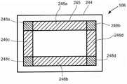
参考图6A,示出了根据本发明一个实施例,用于帮助检测显示器106外框的图案的示例。该显示器106包括外框244和构成显示器106的显示区域的屏幕245。条栅246a、246b、246c和246d分别位于显示器106的上、下、左、右侧,因而强调了外框244的那些边。条栅246a-246d可具有相同的颜色或图案,或者可具有不同的颜色或图案。在一个实施例中,每个条栅具有些微不同的颜色以减少视觉冲击。此外,该颜色可以根据显示器显示的颜色实时变换以减少视觉冲击。该颜色信息可被发送到控制器以通过色彩修正来提高检测精度。角区域248a、248b、248c和248d是具体位于屏幕245的左上、右上、左下和右下角的区域。这些角区域248a-248d从而强调了外框244的角。角区域248a-248d可具有相同的图案或颜色,或者可具有不同的图案或颜色。通过在屏幕245上提供预设的显示图案,例如前述的条栅和角区域,可分析显示器106的所拍摄的RGB图像以确定预设显示图像的位置。且根据RGB图像中的限定了屏幕245和外框244之间的边界的预设显示图案,随后可以更容易地检测到显示器106的外框244。Referring to FIG. 6A , there is shown an example of a pattern used to aid in detecting the bezel of the
参考图6B,示出了根据本发明一个实施例,用于帮助检测显示器106外框的图案的示例。如图所示,在显示器106的屏幕245上显示的图案是网格形图案250。这种图案可用作突出显示器206的外框244以及更好地支持显示器206的外框244的检测。此外,使用这种图案还可有助于展示屏幕245中固有的畸变。Referring to FIG. 6B , an example of a pattern used to aid in detecting the frame of the
为确定与交互程序交互期间控制器100的位置、方向和动作,该控制器100利用它的RGB摄像头226来跟踪显示器的外框。当控制器被移动到不同的位置和方向,由RGB摄像头226捕获的图像中显示器106的大小、形状和方向也随之改变。显示器106的RGB图像中的这些改变是由RGB摄像头226中透镜230的透视畸变和光学性能导致的。To determine the position, orientation and motion of the
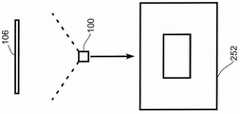
参考图7A、7B和7C,示出了相对于显示器106位于不同位置的控制器100的俯视图。在图7A中,控制器100位于显示器106的正面,使得显示器106出现在由所示RGB摄像头226拍摄的被捕获的图像252中。在图7B中,控制器100已移动到更靠近TV。显示在被捕获图像254中的结果表明当控制器100更接近于显示器106时,显示器106在图像中看上去更大。在图7C中,控制器100已移动到显示器106的左侧。结果,被捕获的图像256中所见的显示器106的图像展现了由控制器100的位置引起的透视畸变。图像256中显示器106的左侧看上去比显示器106的右侧更高,且显示器106的整体外观看上去宽度被缩短。由控制器100的运动引起的透视畸变效果是可预见的,因而,能够通过检查RGB摄像头226的捕获的图像并分析所述显示器的透视畸变来确定控制器100的位置。Referring to Figures 7A, 7B and 7C, top views of the
参考图7D,示出了控制器100相对于显示器106的俯视图,其中控制器100的偏航与图7A中的偏航相比发生了变化。具体地,控制器100的偏航已经相对显示器106逆向转动(朝左边转动)。结果表明在被捕获的图像258中,显示器看上去移到了图像的右边。此外,显示器可呈现某些透视畸变,其中显示器的左侧比右侧看上去短。Referring to FIG. 7D , a top view of the
参考图7E,示出了控制器100相对于显示器106的俯视图,其中控制器100的翻滚与图7A的翻滚相比已经发生变化。具体地,控制器100的翻滚已经相对显示器106正向调整(顺时针旋转)。结果表明在被捕获的图像260中,显示器看上去以向逆时针方向的样式倾斜。Referring to FIG. 7E , a top view of the
参考图7F,示出了控制器100相对于显示器106的侧视图,其中控制器100的俯仰与图7A的俯仰相比已经发生了改变。具体地,控制器100的俯仰已经相对于显示器106正向转动(向上转动)。结果表明在被捕获的图像262中,显示器看上去移向图像的底部。此外,显示器展示特定的透视畸变,其中显示器的上侧比下侧看上去短。Referring to FIG. 7F , a side view of
如前述实施例可见,可通过捕获和分析在控制器100的RGB摄像头捕获的显示器的RGB图像来确定控制器100相对于显示器106的位置和方向。被捕获的RGB图像中显示器106的外观随着控制器100相对于显示器106的位置、偏航、俯仰和翻滚的变化而变化。As seen in the previous embodiments, the position and orientation of the
在本发明的各种实施例中,通过专门跟踪显示器106的外框来跟踪如由RGB摄像头226捕获的显示器106的外观。很多显示器的外框通常是一样的颜色(经常为诸如黑或灰的暗色),其有利于跟踪。此外,很多显示器可具有没有被照亮的显示区域的小的外边界,该外边界也可被跟踪。此外,显示器可包括特性设计项目,例如商标或指示显示器正在运行的指示灯,其在运行期间保持稳定和一致。这些设计项目可提供能够被跟踪用于确定控制器的位置、方向和动作的额外特征。In various embodiments of the invention, the appearance of the
参考图8A,示出了显示器106,其中一组跟踪条栅264显示在显示器106的屏幕245的边缘上。根据本发明的实施例,在由控制器100上的RGB摄像头拍摄的显示器的RGB图像中跟踪所述跟踪条栅264。通过从控制器100跟踪条栅264,以及分析该显示器的图像来确定跟踪条栅的透视畸变、位置和方向,从而确定控制器100的位置、方向和动作。在一些情况下,显示器的外框可能不是很容易确定的,例如当投影仪被用于投射图像到墙壁上或到投射屏幕上。因而,期望可以产生能被跟踪的诸如薄条栅264的边界。Referring to FIG. 8A , the
跟踪条栅264可以采用细线的形式,该细线的厚度根据检测精度和视觉冲击之间的权衡较量而确定。较粗的线可以提供更好的检测以及更好地跟踪显示器,但对视觉显示产生负面影响。然而较细的线会改善视觉外观但由于它们的缩小的外观使得跟踪可能更加困难。The tracking bar 264 may be in the form of thin lines, the thickness of which is determined according to the trade-off between detection accuracy and visual impact. Thicker lines provide better detection and better tracking of the display, but negatively impact the visual display. Thinner lines however improve visual appearance but may be more difficult to track due to their shrunken appearance.
在多个实施例中,跟踪条栅264的颜色或明暗度可能各不相同以减少条栅的视觉冲击。此外,跟踪条栅的颜色可以根据显示器106上正在显示的视频内容的颜色实时地变化,以减少相对于该视频内容该跟踪条栅264的视觉冲击。为了不给在控制器检测跟踪条栅带来负面影响,可以用关于跟踪条栅的当前颜色信息实时地更新该控制器。在一个实施例中,该控制器包括包含有与跟踪条栅264可能显现的颜色相关的颜色的颜色表。在控制器处所捕获的显示器图像中,可以关于跟踪条栅呈现的颜色和形状来估算被捕获的图像,从而帮助确定控制器的位置和动作。In various embodiments, the color or shade of the tracking bars 264 may vary to reduce the visual impact of the bars. Additionally, the color of the tracking bars may change in real time according to the color of the video content being displayed on the
在一个实施例中,为了创建更自然的外观,该跟踪条栅形成矩形色帧,其中显示视频图像。该矩形色帧可以是灰度等级或黑色的,从而最小化它的视觉冲击。In one embodiment, to create a more natural appearance, the tracking bars form a rectangular color frame in which video images are displayed. The rectangular color frame can be grayscale or black to minimize its visual impact.
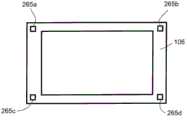
在本发明的其他实施例中,显示器的外框可以变化以便帮助其为了跟踪控制器的检测。例如,参考图8B,示出了具有附接到显示器106的角的反射标签265a、265b、265c和265d的显示器106。反射标签265a-265d提供了可在由控制器的RGB摄像头捕获的显示器的RGB图像中跟踪的外框的区域。为了进一步提高跟踪反射标签265a-265d的能力,它们可以具有特定的图案或颜色,且被设计为与显示器外框244的颜色形成对比。该反射标签可彼此具有不同的图案或颜色,以指示它们所附接的显示器的角。In other embodiments of the invention, the outline of the display may vary to aid in its detection by the controller for tracking purposes. For example, referring to FIG. 8B , a
控制器100旨在被操纵以使用户能与交互程序相接口。由于控制器的位置跟踪取决于能够检测显示器106控制器100,理想的情况是控制器100的RGB摄像头具有尽可能宽阔的视野范围。在不同的实施例中,这可以通过包含多个RGB摄像头和鱼眼透镜来实现。
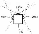
参考图9A,示出了根据本发明的实施例的控制器100。所示的控制器100包括RGB摄像头266a、266b和266c。RGB摄像头266a的视野范围与RGB摄像头266b的视野范围重叠,且RGB摄像头266b的视野范围与RGB摄像头266c的视野范围重叠。通过合并来自多个RGB摄像头266a-266c的视野范围,控制器可用于RGB图像捕获的整体视野范围在270度的范围之内。当所示的RGB摄像头266a-266c排列在大体相同的平面中,可放置附加的摄像头使其被排列在与图9A中所示的平面交叉或横切的平面中。Referring to FIG. 9A , a
参考图9B,示出了根据本发明的实施例的具有360度视野范围的控制器100。所示的控制器100包括多个RGB摄像头268a、268b、268c、268d、268e和268f。这些摄像头每一个的视野范围与两个其他的RGB摄像头的视野范围重叠,从而共同形成360度视野范围。Referring to FIG. 9B , there is shown a
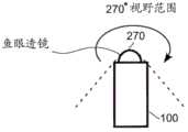
参考图10A,示出了具有包括鱼眼透镜的RGB摄像头270的控制器100。鱼眼透镜提供非常宽阔的可视角度,该可视角度可能在近似270度的范围内。因而,使用鱼眼透镜使RGB摄像头270能够捕获非常宽阔的视野。如本领域所公知的,鱼眼透镜产生相当程度的畸变以便捕获如此宽阔的视野范围到诸如图像传感器的平面空间上。因而在RGB摄像头中结合鱼眼透镜的本发明的实施例中,对由RGB摄像头捕获的RGB图像的分析考虑在使用鱼眼透镜所产生的图像中固有的畸变。Referring to FIG. 10A , a
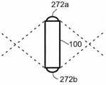
参考图10B,示出了具有两个RGB摄像头272a和272b的控制器100,每个摄像头包含鱼眼透镜。摄像头272a和272b指向相反的方向。摄像头272a和272b的视野范围重叠从而为控制器100提供了360度的视野范围。Referring to FIG. 10B , a
在本发明多个实施例中,在实时跟踪控制器100的期间,可将控制器100的红外功能与RGB图像捕获相结合。例如,在一个实施例中,将经由RGB摄像头对显示器的持续跟踪用作确定控制器的位置和动作的主要方法。然而,当控制器的位置不能通过这个方法获得时,例如当控制器被移动到使得显示器不再位于RGB摄像头的视野范围内时,那么可启动红外投影仪和红外摄像头使得能够确定相对的动作和方向。In various embodiments of the invention, the infrared functionality of the
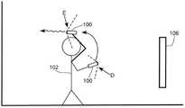
如图11所示,位于位置A的控制器100方向朝向显示器106使得显示器106出现在控制器100的RGB摄像头的视野范围内。因而该控制器100的位置、动作和方向可通过跟踪被捕获的显示器的RGB图像中的显示器106来确定。然而,当控制器100被移动到位置B,由于该控制器当前太接近显示器106使得显示器的外框不再位于RGB摄像头的视野范围内。这种情况下,控制器100的位置不能根据对RGB摄像头捕获的图像的分析来确定。为了继续跟踪控制器100的位置和方向,该控制器100的红外投影仪和红外摄像头被开启。根据上面描述的原理,该红外投影仪产生投影,所述投影被红外摄像头捕获为一系列红外图像。由于在位置B的控制器100太接近显示器106,该投影很可能在显示器106本身的表面上,尽管该投影可能在诸如墙壁的另一表面上。尽管失去了根据RGB图像确定位置的能力,但分析红外摄像头的所捕获的红外图像得到控制器与投影表面的距离和控制器的方向。特别地,通过使用根据RGB图像分析的已知的最新的控制器的方向以及此后启动红外功能和持续跟踪红外投影的变化可以确定该方向。As shown in FIG. 11 , the
当控制器100被移到位置C时产生类似情况,其中控制器100方向朝向侧面274,使得显示器106在控制器的RGB摄像头的视野范围之外。由于显示器106在控制器的RGB摄像头的视野范围外,启动红外投影仪和红外摄像头使得能够在控制器远离显示器106朝向时确定该控制器的位置和方向。A similar situation occurs when
此外,当期望更好地跟踪控制器时,控制器100的红外功能作为基于RGB图像的位置/方向确定的补充可能很有用。例如,继续参考图11,当控制器100移动到远离显示器106的位置诸如位置D,显示器106在控制器的RGB摄像头的视野范围中显得相当小。正因如此,跟踪该显示器变得更加困难,且系统在跟踪显示器方面可能更不稳健。因而,为改进跟控制器的跟踪启动基于红外的跟踪机制来补充RGB图像跟踪机制,并且在控制器的位置/方向仅根据RGB图像分析变得不可确定时作为冗余的系统。Additionally, the infrared functionality of the
当控制器被移动以致引起显示器106要脱离控制器的RGB摄像头的视野时,该RGB摄像头的视野范围中显示器随着时间而发生移动。首先显示器的一或两个角将从视野范围中消失,接着剩下的角也将消失。由于在角从视野消失之前该视野范围中显示器的方向是已知的,并且由于显示器的尺寸已知,因此即使只有显示器的两个角保留在RGB摄像头的视野范围中,继续确定控制器的位置是可能的。然而,由于在此时即将发生无法根据RGB图像来进行控制器的位置确定,理想的方式是在显示器的多于两个角从RGB摄像头的视野范围中消失之前开启红外投影仪和红外摄像机。When the controller is moved so as to cause the
参考图12A、12B和12C,示出控制器100在被操纵远离显示器106时的俯视图。在图12A,控制器面向显示器106使得显示器106全部在控制器的RGB摄像头视野范围之内。这可以在RGB摄像头的捕获的RGB图像276中看到,其中显示器的整体在RGB图像276中可见。在图12B,控制器100已被转向侧面使得只有显示器的两个右角在RGB捕获的图像278中当前可见。由于显示器106的尺寸已知,并且在显示器运动离开RGB摄像头的视野范围之前控制器方向已知,即使只有显示器的两个角在该视野范围中仍然能够确定控制器的位置和方向。然而,显示器的整体即将从该视野范围中消失,由于预期到这种情况的发生,控制器100的红外功能因此被启动。以这种方式,从基于RGB图像的机制到红外机制的过渡是平滑的。在图12C,控制器100的朝向使得显示器106完全在控制器的RGB摄像头的视野范围之外且不出现在RGB摄像头的被捕获的图像280中。此时,系统依靠控制器的红外投影仪和红外摄像头来确定控制器100的位置和方向。Referring to Figures 12A, 12B and 12C, top views of the
参考图13,示出了根据本发明的实施例的持有控制器100的用户102。当用户102在位置D持有该控制器时,该控制器100近似指向显示器106使得该显示器出现在控制器的RGB摄像头的视野范围中。然而,当用户将控制器移动到位置E,该控制器的方向背对显示器106。因而,红外投影仪和红外摄像头被启动并且用于确定控制器100的位置和方向。Referring to FIG. 13 , a
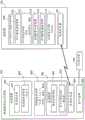
参考图14,示出了用于向交互程序提供控制器输入的系统的逻辑框图。计算机103执行交互程序298,其可以从控制器100接收交互输入。通过显示逻辑306将交互程序显示给用户,该显示逻辑发送视频数据到显示器106用于呈现。控制器100包括无线收发器420用于方便与计算机103的无线通信,该计算机103同样包括无线收发器304。控制器100包括红外投影仪和红外摄像头控制器308,该红外摄像头控制器308根据从计算机103接收的命令控制所述控制器的红外投影仪和红外摄像头的开/关状态。例如,为了确定显示器106的尺寸,该红外投影仪和红外摄像头可被打开用于进行初始化的工作。或者当显示器106在控制器100的RGB摄像头视野范围的外面或几乎在控制器100的RGB摄像头视野范围的外面时,可打开该红外投影仪和红外摄像头。当期望更好地跟踪控制器100时,即使当显示器106在RGB摄像头的视野范围之内(例如当控制器100位于距离显示器106很远的位置)时,也可触发该红外投影仪或红外摄像头。Referring to Figure 14, a logic block diagram of a system for providing controller input to an interactive program is shown. The
红外图像捕获逻辑310控制红外摄像头的红外图像捕获,以诸如每秒60帧的常规帧率提供连续的红外图像流。在不同的实施例中,红外图像流的帧率可高于每秒60帧(例如120fps)或低于每秒60帧。包括用于分析被捕获的红外图像的流的红外图像分析器312。如上所述,该红外摄像头被定向以便捕获由红外投影仪产生的红外投影的图像。因而,红外图像分析器312确定被捕获的红外图像中红外投影的形状、大小和方向。基于该分析,确定控制器100与投影表面的距离,以及确定控制器100的相对俯仰和偏航(或相对翻滚)。Infrared
控制器100还包括RGB摄像头控制器,其控制所述控制器的RGB摄像头的开/关状态。提供RGB图像捕获逻辑316用于控制所述控制器的RGB摄像头的RGB图像捕获,该逻辑以诸如每秒60帧的常规帧率提供连续的RGB图像流。在各个不同实施例中,RGB摄像头的帧率可以比每秒60帧快或者慢。为了位置和方向确认的目的,较高的帧率(例如120fps)产生更好的保真度。RGB图像分析器318执行对被捕获RGB图像帧的初始处理。在一个实施例中,该RGB图像分析器在被捕获的RGB图像中确定显示器的位置和形状。在一个实施例中,这样的数据简化为RGB图像空间中的坐标,该坐标描述了显示器的轮廓。由于控制器的位置/方向的确定需要参考显示器106的尺寸,发送这些坐标到计算机103用于进一步处理。在另一实施例中,该RGB图像分析器对被捕获的RGB图像执行散列处理或压缩。发送压缩的RGB图像到计算机103用于分析以确定图像中显示器的位置和形状。The
计算机103包括RGB数据分析器296,其分析关于来自控制器100的被捕获的RGB图像的数据。更具体地,参考显示器106的真实尺寸来确定被捕获的RGB图像中显示器的位置、形状、大小和方向。同样地,根据被捕获图像中显示器的透视畸变和方向,通过RGB数据分析器296以及通过参考显示器的真实尺寸来确定控制器100的位置和方向。相对于显示器106的位置被确定在3-D空间中,并且控制器100的方向以俯仰、偏航和翻滚的形式被确定。The
尽管所示实施例考虑了在计算机103的RGB数据分析器296的处理,在另一实施例中,RGB数据分析器296的功能在控制器100实现。控制器100可包括使能处理图像数据和最终确定控制器的位置和方向所需的DSP硬件和存储器。控制器100因而可被配置为输出它的相对于显示器106的位置到计算机103。While the illustrated embodiment contemplates processing by RGB data analyzer 296 at
计算机103包括用于通过确定显示器106的尺寸校准控制器的校准逻辑290。出于校准的目的,校准显示单元292使得计算机103输出空白图像或具有特定颜色或图案的图像到显示器106。例如,根据上述校准方法,显示器可以是黑色或暗色的,或者可包括强调显示器106的外框和角的彩色的条栅等。校准数据分析器294根据从控制器100接收的数据确定显示器106的尺寸。从控制器100接收的数据可包括基于红外的控制器100的距离/方向信息,以及包括了如由控制器的RGB摄像头捕获的显示器的RGB图像。根据从控制器100接收的这类的数据,该校准数据分析器确定显示器106的尺寸。The
交互程序298运行在计算机103上。根据本发明的一个实施例,交互程序298包括动态区域确定300,其根据交互程序的运行确定影响控制器100的功能的三维区域。基于位置的功能触发器302根据从控制器接收的输入以及相对于由动态区域确定300确定的区域的控制器的位置,来确定将由交互程序执行的功能。The interactive program 298 runs on the
上述图14的系统构成用于确定控制器100的位置/方向/动作的装置。由校准逻辑290提供用于初始化基于计算机的系统以建立控制器装置相对于显示器的起始位置的装置。由RGB摄像头控制器314提供用于使用控制器装置中集成的摄像头捕获显示器的图像的装置。由红外摄像头控制器308提供用于捕获由控制器装置投射的辐射图案的图像的装置。用于分析所捕获的显示器图像和由控制器装置投射的辐射图案的图像的装置由校准数据分析器294提供,以用来确定在通过所投射的辐射图案的图像确定的控制器装置的距离处所捕获的图像中显示器的大小。由RGB摄像头控制器314提供用于在控制器装置处捕获连续的显示器图像的装置。由RGB图像分析器318和RGB数据分析器296提供用于根据被捕获的连续的显示器的图像中显示器的透视畸变来确定控制器装置相对于显示器的位置的装置。由RGB数据分析器296在向交互程序298提供数据时提供用于向基于计算机的系统提供所确定的控制器的位置以与交互程序相接口从而引发交互程序的动作的装置。由RGB数据分析器296提供用于根据被捕获的显示器图像中显示器的位置和方向确定控制器装置的方向的装置。由RGB图像分析器318和RGB数据分析器296提供用于通过跟踪每个连续图像被捕获时控制器的位置确定控制器装置的动作的装置。用于权利要求17的确定位置的装置,其中由控制器投射的辐射图案是由红外投影仪产生的。The system of FIG. 14 described above constitutes means for determining the position/direction/motion of the
由红外投影仪和摄像头控制器308、红外图像捕获逻辑310,和红外图像分析器312提供用于辅助位置确定的装置。当控制器装置的位置不能根据被捕获的连续的显示器的图像来确定时,用于辅助位置确定的装置被配置来执行如下操作:(1)从所述控制器装置投射辐射图案;(2)在所述控制器装置处捕获连续的该辐射图案的图像;以及(3)根据被捕获的连续的辐射图案的图案估算该控制器装置的位置。Means for assisting in position determination are provided by infrared projector and
在不同的实施例中,无需捕获显示器的整体图像,只要捕获足够实现控制器功能的显示器的一部分。因而,在一个实施例中,配置用于确定位置的装置使得捕获显示器的图像包括捕获足以确定显示器大小的显示器的一部分的图像。在一个实施例中,配置用于确定位置的装置使得捕获连续的显示器的图像包括捕获足以能够确定该控制器装置的位置的连续的显示器的一部分的图像。In various embodiments, it is not necessary to capture an image of the entirety of the display, but only a portion of the display sufficient to implement the functionality of the controller. Thus, in one embodiment, configuring the means for determining a position such that capturing an image of the display includes capturing an image of a portion of the display sufficient to determine the size of the display. In one embodiment, configuring the means for determining position such that capturing images of the contiguous display comprises capturing images of a portion of the contiguous display sufficient to enable determination of the position of the controller device.
在一个实施例中,控制器100可包括手柄和提供扩展功能的单独配件。图15示出了根据本发明一个实施例,具有扩展连接器402的控制器手柄424的组件。尽管限定在权利要求的精神和范围之内的控制器可以有更多或更少的组件,但这些示例性的组件显示了示例的电子设备、硬件、固件和外壳结构以定义可操作的示例。然而,这些示例性的组件不应该限制所要求保护的发明,因为更多或更少的组件是可能的。手柄424被配置为被单手操纵控制器100的用户持有。用户的另一只手自然可以用于握住手柄424或者用于选择手柄424上的按钮。持有控制器100的用户可以通过按下诸如顶部按钮410和底部按钮408的按钮来提供输入。在一个实施例中当配件耦合到手柄424时(诸如图17A中所示的配件),可通过在三维空间中移动控制器来提供输入。为了与计算机103交互,控制器100被配置为无线地操作,这方便了控制器的运动自由。可以用多种方式实现无线通信,例如通过
向手柄424提供扩展功能的配件连接到扩展连接器502以及与扩展连接器402断开。在一个实施例中,配件使得基础计算装置通过配件自身中的摄像头所拍摄图像的视觉识别,能够定位三维空间中手柄和配件的组合。更具体地,且如前所述,根据所捕获图像中显示器106的透视畸变和方向,从在控制器100处所拍摄的图像来确定组合的手柄和配件的位置。其他实施例提供到控制器100的额外通信能力,例如提供与计算机103或游戏区域中其他控制器的超声通信的配件。在又一个实施例中,配件提供红外功能以允许控制器经由红外频率与计算机通信,或使用控制器100作为TV或其他电子设备的远程控制。Accessories that provide extended functionality to the
在一个实施例中,配件与计算机直接通信并且能够按照从计算机接收的命令行事,例如打开内置灯或发出声音。在另一实施例中,手柄424直接控制配件且该配件仅对来自手柄424的命令作出反应。在又一个实施例中,配件能对来自计算机或者手柄的命令做出反应。In one embodiment, the accessory communicates directly with the computer and is able to act on commands received from the computer, such as turning on a built-in light or making a sound. In another embodiment, the
在手柄424内部,印刷电路板416集成了通过总线422互相连接的处理器412、输入/输出(I/O)模块406、存储器416,以及蓝牙模块418。通用串行总线(USB)模块420还提供了与基础计算装置,或其他连接到USB端口432的装置的交互。所述USB端口也能被用于给可充电电池430充电。震动触觉反馈由震动触觉模块428提供。扬声器426提供音频输出。Inside handle 424 , printed circuit board 416 integrates processor 412 , input/output (I/O) module 406 , memory 416 , and Bluetooth module 418 interconnected by bus 422 . Universal Serial Bus (USB) module 420 also provides for interaction with the base computing device, or other devices connected to USB port 432 . The USB port can also be used to charge the rechargeable battery 430 . Vibrotactile feedback is provided by the vibrotactile module 428 . Speaker 426 provides audio output.
应注意,以上控制器配置是示例性的,而且,对本领域普通技术人员而言通过本说明书能够进行另外的一些修改,包括排除或增加模块,并且其是在所要求保护的发明的范围之内的。例如,控制器300还可以包括传感器用于机械地跟踪控制器的运动。It should be noted that the above controller configuration is exemplary, and those of ordinary skill in the art can make some other modifications through this description, including excluding or adding modules, and it is within the scope of the claimed invention of. For example, the
图16描绘了根据一个实施例,具有用于改善运动跟踪的传感器的控制器100。不同的实施例包括传感器的不同组合,例如磁力计434、加速度计436、陀螺仪438等。加速度计是用于测量加速度和重力所引起的反作用力的装置。单轴或多轴模型可用于检测在不同方向上的加速度的大小和方向。加速度计用于感应倾斜、振动和冲击。在一个实施例中,三个加速度计436用于提供重力的方向,其给出了两个角度(世界空间俯仰和世界空间翻滚)的绝对参考。控制器能承受超过5g的加速度,因而在控制器100内部使用能够在超过5g的力的情况下工作的加速度计。FIG. 16 depicts a
磁力计测量控制器附近磁场的强度和方向。在一个实施例中,在控制器内部使用三个磁力计434,其确认世界空间偏航角的绝对参考。磁力计被设计用于跨越地球磁场,其为±80微泰斯拉(microtesla)。磁力计受金属影响,且提供与真实偏航成单调关系的偏航测量。磁场可因为环境中的金属而被扭曲,该扭曲导致偏航测量的扭曲。如果需要,这种扭曲可使用来自陀螺仪(见以下)或摄像头的信息来进行校准。在一个实施例中,加速度计436与磁力计434一起使用以获得控制器的倾斜度和方位角。The magnetometer measures the strength and direction of the magnetic field near the controller. In one embodiment, three magnetometers 434 are used inside the controller, which confirm an absolute reference for the world space yaw angle. The magnetometer is designed to span the Earth's magnetic field, which is ±80 microtesla. The magnetometer is affected by metal and provides a yaw measurement that is monotonically related to the true yaw. The magnetic field can be distorted by metal in the environment, which distorts the yaw measurement. This distortion can be calibrated using information from the gyroscope (see below) or the camera, if desired. In one embodiment, accelerometer 436 is used with magnetometer 434 to obtain the inclination and azimuth of the controller.
陀螺仪是用于基于角动量原理用于测量或保持方向的装置。在一个实施例中,三个陀螺仪基于惯性传感提供关于穿过相应轴(x、y和z)的运动信息。所述陀螺仪帮助检测快速旋转。然而,螺旋仪能够随着时间漂移而无需绝对参考的存在。这要求周期地重置陀螺仪,该重置可以通过使用其他可用信息完成,例如根据可视化跟踪显示器106、加速度计、磁力计等确定位置/方向。手持装置能够以快于每秒500度的角速度旋转,因而推荐规格超过每秒1000度的陀螺仪,但是更小的值也是可能的。A gyroscope is a device for measuring or maintaining orientation based on the principle of angular momentum. In one embodiment, three gyroscopes provide information about motion through respective axes (x, y, and z) based on inertial sensing. The gyroscope helps detect rapid rotation. However, gyroscopes are capable of drifting over time without the existence of an absolute reference. This requires resetting the gyroscope periodically, which can be done using other available information, such as determining position/orientation from the
来自不同来源的信息可被结合用于改进的位置和方向检测。例如,如果移动或定向控制器使得显示器不再位于RGB摄像头的视野范围之内,那么使用加速度计的方向传感来检测控制器正从显示器转向别处。在一个实施例中,控制器100包括扬声器426用于向玩家提供音频反馈。当显示器不在RGB摄像头的视野范围内时,控制器能够产生蜂鸣声,提示玩家将控制器定向到正确方向或回到游戏区域。Information from different sources can be combined for improved position and orientation detection. For example, if the controller is moved or oriented such that the display is no longer within the RGB camera's field of view, use the accelerometer's orientation sensing to detect that the controller is turning away from the display. In one embodiment, the
图17A描述了用于手柄424的具有“丰富”部件集的配件502。应该注意到图17A示出的实施例是示例性的,且其他实施例可包括配件502的部件子集。因而,图17A中所示的实施例不应该理解为排他性或者限制性的,而仅是示例性或者示意性的。FIG. 17A depicts an
球形配件502中不同模块经由通用总线互相连接,但其他互连机制可能的。连接器504提供将配件502从控制器连接或断开的接口。配件502包括处理器或电路加内存允许配件处理计算机指令。而且,配件502包括诸如超声、红外和WiFi的通信模块。此类通信使配件能与计算机或其他电子装置通信,此处将其称为控制器与计算机或者其他电子装置之间的通信接口。在一个实施例中,配件作为调制解调器运行,从控制器接收信息并且转发信息到计算机,反之亦然。The different modules in ball fitting 502 are interconnected via a common bus, but other interconnection mechanisms are possible.
由配件接收并传到控制器的信息用于改变控制器的状态。例如,控制器可发出声音、改变按钮配置、禁用控制器、在内存加载寄存器、发送发光命令到配件等。计算机接收到的信息由交互程序使用以更新交互程序的状态。例如,交互程序可在屏幕上移动化身或改变化身的状态、发动攻击、启动游戏、选择菜单选项等。Information received by the accessory and passed to the controller is used to change the state of the controller. For example, the controller can make sounds, change button configurations, disable the controller, load registers in memory, send light commands to accessories, etc. The information received by the computer is used by the interactive program to update the state of the interactive program. For example, the interactive program may move the avatar on the screen or change the state of the avatar, launch an attack, launch a game, select a menu option, and the like.
加速度计、磁力计和陀螺仪提供与配件运动相关的机械信息。在一个实施例中,结合机械或惯性信息和其他位置确认信息(诸如对显示器的视觉跟踪)以改进控制器-配件结合物的位置的确定。Accelerometers, magnetometers, and gyroscopes provide mechanical information about the accessory's motion. In one embodiment, mechanical or inertial information is combined with other position confirmation information, such as visual tracking of a display, to improve the determination of the position of the controller-accessory combination.
内置发光装置允许配件从内部发光以向用户提供反馈。在一个实施例中,发光装置可以发出单个颜色的光,而在另一个实施例中,发光装置可被配置为根据选择的颜色发光。在又一个实施例中,配件502包括好几个发光装置,其中每个发光装置能发出一种颜色的光。发光装置被配置为发出不同级别的亮度。计算机能够通过改变配件502的发光状态、产生音频信号或用触觉震动反馈等向持有控制器的用户提供交互。一个反馈操作或者反馈操作的组合是可行的。在一个实施例中,从预定义的交互性列表,且基于游戏中所发生的事情选择反馈类型。A built-in light-emitting device allows the accessory to glow from within to provide feedback to the user. In one embodiment, the light emitting device can emit light of a single color, while in another embodiment, the light emitting device can be configured to emit light according to a selected color. In yet another embodiment,
麦克风和扬声器提供音频功能,而电池为其余组件(包括控制器和发光装置)提供电力。电池也可被手柄用作第二电源。例如,如果控制器中的可充电电池放电,配件能够提供所需电力从而用户可以持续游戏而不是停下来对控制器再充电。在一个实施例中,配件502不包括电池且经与手柄的电源的电连接获得输入到配件502中模块的电力。A microphone and speaker provide the audio functions, while a battery provides power for the rest of the components, including the controller and lights. The battery can also be used by the handle as a secondary power source. For example, if the rechargeable battery in the controller discharges, the accessory can provide the power needed so the user can continue gaming instead of stopping to recharge the controller. In one embodiment,
红外投影仪和红外摄像头提供红外功能用于确定控制器的相对位置和方向。RGB摄像头捕获显示器的RGB图像使得控制器的位置可根据所捕获RGB图像中显示器的透视畸变和方向来确定。Infrared projectors and infrared cameras provide infrared functionality for determining the relative position and orientation of the controller. The RGB camera captures an RGB image of the display so that the position of the controller can be determined based on the perspective distortion and orientation of the display in the captured RGB image.
USB模块允许照射到配件或者来自配件的USB通信。在一个实施例中,使用USB连接给配件中的电池充电。在又一个实施例中,配件502包括被传输到控制器、或计算机、或控制器和计算机两者的内存中文件。所述内存中文件能包括被传输用于在控制器或游戏系统中执行的配置文件或程序。该文件能用于识别特定用户、配置控制器或基础系统,加载游戏、增加部分功能到现有游戏等。例如,一个文件是被装载到计算机用来玩的游戏、另一文件包括能用于跟唱游戏的卡拉OK歌曲,另一文件包括新玩家登记表和统计资料用于对体育游戏的更新等。此外,配件能被用于存储诸如对于特定游戏的玩家配置的用户参数。随后玩家能使用从原始游戏系统获得的配置在不同的游戏系统使用该配件与其他玩家玩游戏。The USB module allows for USB communication to and from the accessory. In one embodiment, the battery in the accessory is charged using the USB connection. In yet another embodiment,
图17B示出了其中图17A的配件被连接到图15的控制器的实施例。在一个实施例中,配件502与控制器424经由诸如USB接口的通信接口进行交互。在另一实施例中,配件502与控制器424中的一个或多个内部模块电通信。例如,配件502的处理器/电路(参见图17A)连接到控制器424的总线422(参见图15),因而允许配件502的处理器与附接到总线的控制器中的模块通信。配件502的处理器能够访问内存416以直接写或读数据,或者为控制器424的处理器/电路412产生中断以发出必需由处理器412处理的外部事件信号。FIG. 17B shows an embodiment in which the accessory of FIG. 17A is connected to the controller of FIG. 15 . In one embodiment,
应注意,图17B中描述的实施例是示例性的,且其他实施例可包括较少的组件。It should be noted that the embodiment depicted in Figure 17B is exemplary and other embodiments may include fewer components.
图18示出了根据本发明一个实施例,可用于确定控制器位置的硬件和用户接口。图18示意性地示出了


I/O桥534还连接六个通用串行总线(USB)2.0端口524、千兆以太网端口522、IEEE 802.11b/g无线网络(Wi-Fi)端口520和最多可以支持七个蓝牙连接的蓝牙
在操作中,I/O桥534处理所有无线、USB和以太网数据,包括来自一个或者多个游戏控制器502-503的数据。例如,当用户玩游戏时,I/O桥534经蓝牙链接接收来自游戏控制器502-503的数据,并且将其转发到Cell处理器528,所述Cell处理器528相应地更新游戏的当前状态。In operation, I/O bridge 534 handles all wireless, USB and Ethernet data, including data from one or more game controllers 502-503. For example, when a user is playing a game, the I/O bridge 534 receives data from the game controllers 502-503 via the Bluetooth link and forwards it to the
无线、USB和以太网端口还提供到除了游戏控制器502-503以外的其他外围设备的连接,例如,远程控制器504、键盘506、鼠标508、便携式娱乐装置510(如索尼Playstation

所提供的这些接口意味着PlayStation 3装置也潜在地兼容诸如数字视频录像器(DVR)、机顶盒、数字照相机、便携式媒体播放器、IP上的语音电话、移动电话、打印机和扫描仪的其它外围设备。The interfaces provided mean that the
此外,现有的存储器读卡器516可以通过USB端口524连接到系统单元,使得可读取或装置所使用的那类存储卡548。Additionally, an existing memory card reader 516 can be connected to the system unit via the USB port 524, making it possible to read or The type of memory card used by the device 548.
游戏控制器502-503可操作地经由蓝牙链接和系统单元500无线通信,或者连接到USB端口,从而还提供为游戏控制器502-503的电池充电的电源。游戏控制器502-503还可包括存储器、处理器、存储器读卡器、如闪速存储器的永久存储器、如照亮的球形部分、LED或红外灯的发光器、用于超声通信的麦克风和扬声器、声学腔、数码相机、内部时钟、朝向游戏控制台的可识别形状(如球形部分),以及使用如
游戏控制器502是设计成两手使用的控制器,游戏控制器503是具有配件的单手操作控制器。除了一个或多个模拟操纵杆和传统控制按钮外,游戏控制器对三维位置的确定敏感。因而,游戏控制器的用户的姿态和动作可以被转换成游戏的输入,这可以是除了传统按钮或操作杆命令之外的游戏的输入,或者作为传统按钮或操作杆命令的替代。可选地,其他支持无线模式的外围设备,例如PlaystationTM便携装置,可用作控制器。在使用PlaystationTM便携装置的情况下,可以在装置的屏幕上提供额外的游戏或控制信息(例如,控制指令或生命数)。也可以使用其他替代或补充的控制设备,例如跳舞毯(未示出)、光枪(未示出)、方向盘和踏板(未示出)或者定做的控制器,例如快速响应问答游戏的一个或多个大的按钮(也未示出)。
远程控制器504同样可操作地经蓝牙链接与系统单元500无线通信。远程控制器504包括适用于Blu RayTM盘BD-ROM读取器(Blu RayTM DiskBD-ROM reader)540的操作的控制和适用于导航光盘内容的控制。The
Blu RayTM盘BD-ROM读取器540可操作地用于读取与PlayStation和PlayStation 2设备兼容的CD-ROM,和传统预刻录和可刻录CD以及所谓的超级音频CD。除了传统的预先刻录的以及可刻录的DVD外,读取器540还可可操作地用于读与Playstation2以及Playstation3装置兼容的DVD-ROM。另外,读取器540还可操作地用于读与Playstation3装置兼容的BD-ROM以及传统的预先刻录和可刻录蓝光光盘。The Blu Ray™ disc BD-ROM reader 540 is operable to read CD-ROMs compatible with PlayStation and
系统单元500可操作地用于通过音频和视频连接器将视频和音频提供给显示和声音输出装置542,所述音频和视频是由Playstation3装置通过真实合成图形单元530产生或解码的,显示和声音输出装置542如具有显示屏544以及一个或多个扬声器546的监视器或者电视机。音频连接器550可以包括传统模拟和数字输出,而视频连接器552可以多样地包括分量视频、S-视频、复合视频以及一个或多个高清多媒体接口(HDMI)输出。因此,视频输出可以采用的格式诸如PAL或者NTSC,或者以720p、1080i或1080p的高清晰度格式。The system unit 500 is operable to provide video and audio generated or decoded by the
Cell处理器528执行音频处理(产生、解码等等)。Playstation 3装置的操作系统支持5.1环绕立体声、

本实施例中,视频摄像头512包括单个电荷耦合装置(CCD)、LED指示器,和基于硬件的实时数据压缩和编码设备,这样,可以发送用例如基于图像内的MPEG(运动图像专家组)标准的适当的格式压缩的视频数据,以由系统单元500进行解码。摄像头LED指示器被设置成响应来自系统单元500的适当的控制数据来发光,例如,以表示不利的光照条件。视频摄像头512的不同实施例可以通过USB、蓝牙或者Wi-Fi通信端口连接到系统单元500。视频摄像头的实施例可以包括一个或者多个相关联的麦克风并且也可以传输音频数据。在视频摄像头的实施例中,CCD可以具有适用于高清晰度视频捕获的分辨率。在使用中,视频摄像头所捕获的图像例如可以被包括在游戏中或者被解释为游戏的控制输入。在另一实施例中,摄像头是适用于检测红外光的红外摄像头。In this embodiment, video camera 512 includes a single charge-coupled device (CCD), LED indicator, and hardware-based real-time data compression and encoding equipment, so compressed video data in an appropriate format to be decoded by the system unit 500. The camera LED indicator is configured to illuminate in response to appropriate control data from the system unit 500, eg, to indicate adverse lighting conditions. Different embodiments of the video camera 512 can be connected to the system unit 500 via a USB, Bluetooth or Wi-Fi communication port. Embodiments of the video camera may include one or more associated microphones and may transmit audio data as well. In a video camera embodiment, the CCD may have a resolution suitable for high definition video capture. In use, images captured by the video camera may, for example, be included in a game or interpreted as control input for the game. In another embodiment, the camera is an infrared camera adapted to detect infrared light.
总的来说,为了通过系统单元500的其中一个通信端口与诸如视频摄像头或者远程遥控的外围设备产生成功的数据通信,应该提供诸如设备驱动器的适当的软件。设备驱动技术是公知的,在此不做详细描述,但是本领域技术人员应明白所描述的本实施例可能需要设备驱动或类似的软件接口。In general, in order to have a successful data communication with a peripheral device such as a video camera or a remote control through one of the communication ports of the system unit 500, appropriate software such as a device driver should be provided. The device driver technology is well known and will not be described in detail here, but those skilled in the art should understand that the described embodiment may require a device driver or a similar software interface.
图19示出根据本发明一个实施例,可用于处理指令的额外硬件。Cell处理器528具有包括四个基本组件的架构:外部输入和输出结构,包括存储器控制器660和双总线接口控制器670A、B;称为Power处理部件650的主处理器;称为协处理部件(Synergistic Processing Element,SPE)610A-H的八个协处理器;以及连接上述组件的环形数据总线,其被称为部件互联总线680。和Playstation2装置的Emotion Engine的6.2GFLOP相比,Cekll处理器的总体浮点性能是218GFLOPS。Figure 19 illustrates additional hardware that may be used to process instructions according to one embodiment of the present invention. The
Power处理部件(PPE)650基于以3.2GHz的内部时钟运行的双向同时多线程Power 570兼容的PowerPC核(PPU)655的。Power处理部件(PPE)650包括512kB 2级(L2)高速缓冲存储器和32kB 1级(L1)高速缓冲存储器。PPE 650每时钟周期能够进行八个单精度操作,在3.2GHz下换算为25.6GFLOPS。PPE 650的基本作用是作为协同处理部件610A-H的控制器,处理大部分计算工作量。在操作中,PPE 650维护一个作业队列,为协处理部件610A-H调度作业,并且监控其进度。因而,每个协处理部件610A-H运行一个内核,其作用是获得作业、执行该作业并和PPE650同步。The Power Processing Element (PPE) 650 is based on a bidirectional simultaneous multi-threaded Power 570 compatible PowerPC Core (PPU) 655 running at an internal clock of 3.2GHz. The Power Processing Element (PPE) 650 includes 512kB Level 2 (L2) cache memory and 32kB Level 1 (L1 ) cache memory. The
每个协处理部件(SPE)610A-H包括相应的协处理单元(SPU)620A-H,和相应的存储器流控制器(MFC)640A-H,其进而包括相应的动态存储器存取控制器(DMAC)642A-H,相应的存储器管理单元(MMU)644A-H和总线接口(未示出)。每个SPU 620A-H是RISC处理器,时钟为3.2GHz,包括256kB本地RAM 630A-H,原则上可扩展到4GB。每一SPE给出理论上25.6GFLOPS的单精度性能。SPU在单个时钟周期内可以处理4个单精度浮点数、4个32位数、8个16位整数或者16个8位整数。在同一个时钟周期内,也可以执行存储器操作。SPU 620A-H不直接访问系统存储器XDRAM 526,将SPU 620A-H形成的64位地址传递给MFC 640A-H,MFC 640A-H指示其DMA控制器642A-H通过部件互联总线680和存储器控制器660访问存储器。Each co-processing element (SPE) 610A-H includes a corresponding co-processing unit (SPU) 620A-H, and a corresponding memory flow controller (MFC) 640A-H, which in turn includes a corresponding dynamic memory access controller ( DMACs) 642A-H, corresponding memory management units (MMUs) 644A-H and bus interfaces (not shown). Each
部件互联总线(EIB)680为Cell处理器528内部的逻辑循环通信总线,用来连接上述处理器部件,也就是PPE 650、存储器控制器660、双总线接口670A、B以及8个SPE 610A-H,共12参与部件。参与部件可以同时以每时钟周期8字节的速率读和写总线。如前所述,每一个SPE610A-H包括DMAC 642A-H用于调度更长的读或者写序列。EIB包括四个通道,两个顺时针方向,两个逆时针方向。因而,对于十二个参与部件,任意两个参与部件之间的最长步进式(step-wise)数据流在适当的方向是六步。因此在参与部件之间通过裁决全面利用的情况下,对于12槽(slot)的理论峰值瞬时EIB带宽为每时钟96B。这等于在3.2GHz时钟速率的307.2GB/s的理论峰值带宽。Component Interconnection Bus (EIB) 680 is a logical loop communication bus inside
存储器控制器660包括由Rambus公司开发的XDRAM接口662。存储器控制器和Rambus XDRAM 526以理论峰值带宽25.6GB/s相接口。双总线接口670A、B包括Rambus
由Cell处理器528发送到真实模拟器图形单元530的数据通常包括显示列表,其作为命令的序列来画出顶点、对多边形应用纹理、指定光照条件等等。Data sent by
图20是根据本发明的一个实施例,与经互联网连接到服务器处理的游戏客户机702交互的相应用户A到用户E的场景A到E的示例图示。游戏客户机是允许用户通过互联网连接到服务器应用和处理的装置。游戏客户机使得用户可访问并重放在线娱乐内容,其包括但不限于游戏、电影、音乐和照片。此外,游戏客户机可提供对在线通信应用的访问,如VOIP、文本聊天协议和电子邮件。20 is an exemplary illustration of scenarios A through E of respective users A through E interacting with a game client 702 connected to a server process via the Internet, according to one embodiment of the present invention. A game client is a device that allows a user to connect to server applications and processes over the Internet. The game client enables users to access and playback online entertainment content, including but not limited to games, movies, music and photos. Additionally, the game client can provide access to online communication applications such as VOIP, text chat protocols, and email.
用户通过控制器和游戏客户机交互。一些实施例中,控制器是游戏客户机专用的控制器,而在其他实施例中,控制器可以是键盘和鼠标的组合。在一个实施例中,游戏客户机是可以输出音频和视频信号以通过监视器/电视和相关音频设备形成多媒体环境的独立装置。例如,游戏客户机可以是但不限制于:瘦客户端、内部PCI-扩展卡、外部PCI-扩展装置、扩展卡装置、内部、外部或无线USB装置,或者火线装置等。在其他实施例中,游戏客户机与电视或其他诸如DVR、蓝光播放器、DVD播放器或多通道接收器的多媒体装置集成。The user interacts with the game client through the controller. In some embodiments, the controller is a game client-specific controller, while in other embodiments, the controller may be a keyboard and mouse combination. In one embodiment, the game client is a standalone device that can output audio and video signals to create a multimedia environment through a monitor/television and associated audio equipment. For example, a game client can be, but is not limited to, a thin client, an internal PCI-expansion card, an external PCI-expansion device, an expansion card device, an internal, external or wireless USB device, or a Firewire device, among others. In other embodiments, the game client is integrated with a television or other multimedia device such as a DVR, Blu-ray player, DVD player, or multi-channel receiver.
图20的场景A中,用户A使用和游戏客户机702A配对的控制器100和监视器106上显示的客户机应用交互。类似地,场景B中,用户B使用和游戏客户机702B配对的控制器100和监视器106上显示的另一个客户机应用交互。场景C示出当用户C看着显示来自游戏客户机702C的游戏和好友列表的监视器时,从用户C背后看的场景。图20示出一个服务器处理模块,一个实施例中,有多个服务器处理模块遍布全世界。每个服务器处理模块包括子模块,用于用户会话控制、共享/通信逻辑、用户地理位置和负载平衡处理服务。此外,服务器处理模块包括网络处理和分布式存储。In scenario A of FIG. 20 , user A interacts with a client application displayed on
游戏客户机702连接到服务器处理模块时,用户会话控制可用于认证用户。经认证的用户可具有相关的虚拟化分布式存储和虚拟化网络处理。可作为用户的虚拟化分布式存储的部分的示例项目包括购买的媒体,例如但不限制于游戏、视频和音乐等。此外,分布式存储可用于保存多个游戏的游戏状态、为个人游戏定制的设置,以及为游戏客户机的通用设置。一个实施例中,服务器处理的用户地理位置模块用于确定用户的地理位置以及他们的相应游戏客户机。用户的地理位置可由共享/通信逻辑和负载平衡处理服务用于根据地理位置和多个服务器处理模块的处理要求来优化性能。对网络处理和网络存储中的一个或两者进行虚拟化允许游戏客户机的处理任务动态地转移到未充分使用的服务器处理模块。因而,负载平衡可用于使得和从存储中调用关联的延迟以及和服务器处理模块与游戏客户机之间的数据传输关联的延迟都最小。When the game client 702 is connected to the server processing module, user session control may be used to authenticate the user. Authenticated users may have associated virtualized distributed storage and virtualized network processing. Example items that may be part of the user's virtualized distributed storage include purchased media such as, but not limited to, games, videos, music, and the like. Additionally, distributed storage can be used to save game state for multiple games, settings customized for individual games, and general settings for game clients. In one embodiment, a server-processed user geolocation module is used to determine the geographic location of users and their corresponding game clients. The user's geographic location may be used by the sharing/communication logic and load balancing processing services to optimize performance based on the geographic location and processing requirements of the multiple server processing modules. Virtualizing one or both of network processing and network storage allows game client processing tasks to be dynamically offloaded to underutilized server processing modules. Thus, load balancing can be used to minimize both the latency associated with calls from storage and the latency associated with data transfer between the server processing module and the game client.
如图20所示,服务器处理模块具有服务器应用A的实例和服务器应用B的实例。如服务器应用X1和服务器应用X2所指示的,服务器处理模块能够支持多个服务器应用。在一个实施例中,服务器处理基于集群计算架构,其允许一个集群内的多个处理器处理服务器应用。在另一个实施例中,用不同类型的多计算机处理方案来处理服务器应用。这允许服务器处理可被扩展,以适应更多的执行多个客户机应用的游戏客户机以及相应的服务器应用。或者,服务器处理可被扩展以适应增加的计算需求或应用复杂度,增加的计算需求是更苛刻的图形处理或游戏、视频压缩所需要的。一个实施例中,服务器处理模块通过服务器应用执行大部分处理。这允许相对较贵的部件(比如图形处理器、RAM和通用处理器)位于中央位置,并降低了游戏客户机的成本。通过互联网把处理过的服务器应用数据发送回相应的游戏客户机,以显示在监视器上。As shown in FIG. 20 , the server processing module has an instance of server application A and an instance of server application B. As indicated by server application X1 and server application X2, the server processing module is capable of supporting multiple server applications. In one embodiment, server processing is based on a cluster computing architecture that allows multiple processors within a cluster to process server applications. In another embodiment, a different type of multi-computer processing scheme is used to process the server application. This allows server processing to be scaled to accommodate more game clients executing multiple client applications and corresponding server applications. Alternatively, server processing can be scaled to accommodate increased computational demands or application complexity, as required for more demanding graphics processing or gaming, video compression. In one embodiment, the server processing module performs most of the processing through the server application. This allows relatively expensive components such as graphics processors, RAM, and general-purpose processors to be centrally located and reduces the cost of game clients. The processed server application data is sent back to the corresponding game client via the Internet for display on the monitor.
场景C示出游戏客户机和服务器处理模块可执行的示例应用。例如在一个实施例中,游戏客户机720C允许用户C创建和观看包括用户A、用户B、用户D和用户E的好友列表。如图所示,在场景C中,用户C能够看到实时图像或者监视器106C上的相应用户的化身。服务器处理执行游戏客户机702C和用户A、用户B、用户D和用户E的相应的游戏客户机702的相应应用。由于服务器处理知道正被游戏客户机B执行的应用,用户A的好友列表可指示游戏用户B正在玩什么游戏。更进一步,在一个实施例中,用户A可以直接观看游戏视频中来自用户B的实况。这仅由通过发送用户B的经处理的服务器应用数据到游戏客户机A和游戏客户机B来实现。Scenario C illustrates an example application executable by the game client and server processing modules. For example, in one embodiment, game client 720C allows User C to create and view a buddy list that includes User A, User B, User D, and User E. As shown, in scene C, user C is able to see the live image or avatar of the corresponding user on
除了可以观看好友的视频外,通信应用可以允许好友之间进行实时通信。如应用到先前示例,这允许用户A在观看用户B的实时视频时提供鼓励或提示。在一个实施例中,通过客户机/服务器应用建立双向实时音频通信。另一个实施例中,客户机/服务器应用支持文本聊天。另一个实施例中,客户机/服务器应用将语音转成文本,以显示在好友屏幕上。In addition to watching videos of friends, communication applications can allow real-time communication between friends. As applied to the previous example, this allows User A to provide encouragement or prompts while watching User B's live video. In one embodiment, two-way real-time audio communication is established through a client/server application. In another embodiment, the client/server application supports text chat. In another embodiment, the client/server application converts speech to text for display on the buddy screen.
场景D和场景E分别示出相应的用户D和用户E分别和游戏控制台710D和710E交互。每个游戏控制台710D和710E连接到服务器处理模块,并示出网络,在该网络中,服务器处理模块为游戏控制台和游戏客户机协调游戏的运行。Scene D and scene E respectively show corresponding user D and user E interacting with
参考图21A,描述了根据本发明的实施例的用于初始化动作控制器来确定TV显示器(或其它类型显示器)的大小的方法800。在方法操作801,用户持有指向TV显示器的控制器。在方法操作802,该TV显示用于校准目的的黑色图像或者静态图像。在其他实施例中,由TV显示器显示的状态或图像可以是任何状态(例如开/关、随着时间而改变(例如闪光))或图像,或者只要TV显示器可识别的任何级别的图像亮度。在方法操作803,控制器上的红外投影仪向TV显示器或向TV显示器坐落的位置的方向投影光束图案(或无图案的光束)。在方法操作804,控制器上的红外摄像头捕获由TV显示器反射的光束图案的红外图像。在方法操作805,分析被捕获的红外图像,并且根据该红外光束图案的大小/畸变,确定控制器相对于TV显示器的深度Z、偏航和俯仰。在方法操作806,该RGB摄像头检测TV显示器的外框。在方法操作807,方法操作805和805的结果用于产生对TV显示器物理大小的估值。Referring to FIG. 21A , a
参考图21B,描述了根据本发明的一个实施例,用于用RGB摄像头实时跟踪TV显示器外框的方法810。在方法操作811,分析该外框的大小/畸变。在方法操作812,产生相对于TV显示器的控制器的x/y/z位置和俯仰/偏航。在方法操作813由加速度计估算翻滚角。Referring to FIG. 21B , a
在本发明的另一实施例中,控制器中包括激光距离测量,来代替使用红外投影仪和红外摄像头。参考图22,描述了根据本发明一个实施例的使用激光距离测量来校准TV显示器物理大小的方法。在方法操作821,用户持有指向TV显示器的控制器。在方法操作822,该控制器向TV屏幕发射激光。在方法操作823,确定距离测量。在方法操作824,RGB摄像头检测TV显示器的外框和激光点。在方法操作825,使用加速度计确定俯仰/翻滚。在方法操作826,假设TV显示器通常为矩形几何形状,且基于此,产生对TV显示器的物理大小的估算。In another embodiment of the invention, laser distance measurement is included in the controller instead of using an infrared projector and infrared camera. Referring to FIG. 22 , a method of calibrating the physical size of a TV display using laser distance measurement according to one embodiment of the present invention is described. At
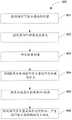
参考图23,描述了根据本发明的实施例用于提供与交互程序相接口的方法830。在方法操作831,从控制器向显示器或大体朝向显示器的方向投射光束。在方法操作832,通过检查所投射光束的被捕获图像来确定所投射光束的大小。在方法操作833,通过确定所投射光束的大小确定从控制器到显示器的距离。在方法操作834,在控制器处捕获显示器的图像。该显示器可被配置为产生任何类型的图像/视频,或什么也不产生,以便帮助识别所捕获的显示器图像中的显示器。在方法操作835,根据对所捕获的显示器图像的分析和所确定的到显示器的距离来确定显示器的尺寸。在方法操作836,在控制器处捕获连续的显示器的图像。分析这些连续的显示器的图像以确定控制器的位置/方向/动作。在方法操作837,提供所确定的控制器的位置/方法/动作作为到交互程序的输入,以便引发交互程序中的动作。Referring to FIG. 23 , a
本发明的实施例可以与各种计算机系统配置一起实施,包括手持式装置、微处理器系统、基于微处理器的或可编程的消费电子产品、小型计算机、大型计算机以及类似装置。本发明也可以在分布式计算环境中实现,其中通过经由基于有线或无线网络链接的远程处理装置来执行任务。Embodiments of the invention may be practiced with various computer system configurations, including handheld devices, microprocessor systems, microprocessor-based or programmable consumer electronics, minicomputers, mainframe computers, and the like. The invention can also be practiced in distributed computing environments where tasks are performed by remote processing devices through a wired or wireless network link.
考虑到上述实施例,应当理解本发明可以使用涉及计算机系统所存储的数据的多种计算机实施的操作。这些操作是需要对物理量进行物理处理的操作。此处描述的构成本发明的部分的任一操作都是有用的机器操作。本发明同样涉及用于执行这些操作的设备或装置。此设备可以根据所需目的特别构建,或者可以由存储在计算机中的计算机程序可选地配置或者激活的通用计算机。更具体地,根据此处教导,可以将计算机程序用于不同的通用机器,或者更方便地可以构建更专用设备来执行所需操作。With the above embodiments in mind, it should be understood that the invention may employ a variety of computer-implemented operations involving data stored by computer systems. These operations are those requiring physical manipulations of physical quantities. Any of the operations described herein that form part of the invention are useful machine operations. The invention also relates to a device or apparatus for performing these operations. This apparatus may be specially constructed for the required purposes, or it may be a general-purpose computer optionally configured or activated by a computer program stored in the computer. More specifically, in light of the teachings herein, a computer program may be used in different general purpose machines, or, more conveniently, a more specialized apparatus may be constructed to perform the required operations.
本发明还可以实现为计算机可读介质上的计算机可读代码。该计算机可读介质可以是能够存储可被计算机系统随后读取的数据的任何数据存储装置。计算机可读介质的示例包括硬盘驱动器、网络附加存储(NAS)、只读存储器、随机存取存储器、CD-ROM、CD-R、CD-RW、磁带以及其他光学和非光学数据存储装置。计算机可读介质可以包括分布在网络耦合的计算机系统上的计算机可读有形介质,这样,计算机可读代码以分布式的方式存储和执行。The invention can also be embodied as computer readable code on a computer readable medium. The computer readable medium can be any data storage device that can store data which can be thereafter read by a computer system. Examples of computer readable media include hard drives, network attached storage (NAS), read only memory, random access memory, CD-ROM, CD-R, CD-RW, magnetic tape, and other optical and non-optical data storage devices. The computer readable medium can include computer readable tangible medium distributed over network coupled computer systems so that the computer readable code is stored and executed in a distributed fashion.
尽管以特定顺序描述所述方法操作,但应理解其它管理操作可以在这些操作之间执行,或者操作可以进行调整,使其得在稍微不同的时间进行,或者可以分布在允许与处理相关的不同时间间隔处发生处理操作的系统中,只要覆盖操作的处理以期望方式执行。Although the method operations are described in a particular order, it should be understood that other administrative operations may be performed between these operations, or that operations may be adjusted to occur at slightly different times, or may be distributed to allow for processing-related differences. In systems where processing operations occur at time intervals, as long as the processing of the overriding operations is performed in the desired manner.
虽然为清晰理解的目的对上述发明的一些细节进行了详细描述,但显然,可以在所附的权利要求的范围内进行一些变化和修改。因而,这些实施例应当被认为是示例性的而非限制性的,本发明不限于这里描述的细节,而是可在所附权利要求及其等价内容的范围内进行修改。Although the foregoing invention has been described in detail for purposes of clarity of understanding, it will be apparent that changes and modifications may be practiced within the scope of the appended claims. Accordingly, the embodiments should be considered as illustrative and not restrictive, the invention not being limited to the details described herein but may be modified within the scope of the appended claims and their equivalents.
Claims (29)
Translated fromChinesePriority Applications (1)
| Application Number | Priority Date | Filing Date | Title |
|---|---|---|---|
| CN201310108286.0ACN103218055B (en) | 2010-02-05 | 2010-11-23 | For the controller using position, direction or action and calculation procedure interfaces |
Applications Claiming Priority (3)
| Application Number | Priority Date | Filing Date | Title |
|---|---|---|---|
| US30207110P | 2010-02-05 | 2010-02-05 | |
| US61/302071 | 2010-02-05 | ||
| PCT/US2010/057905WO2011096976A1 (en) | 2010-02-05 | 2010-11-23 | Controller for interfacing with a computing program using position, orientation, or motion |
Related Child Applications (1)
| Application Number | Title | Priority Date | Filing Date |
|---|---|---|---|
| CN201310108286.0ADivisionCN103218055B (en) | 2010-02-05 | 2010-11-23 | For the controller using position, direction or action and calculation procedure interfaces |
Publications (2)
| Publication Number | Publication Date |
|---|---|
| CN102918476Atrue CN102918476A (en) | 2013-02-06 |
| CN102918476B CN102918476B (en) | 2017-03-08 |
Family
ID=43530326
Family Applications (2)
| Application Number | Title | Priority Date | Filing Date |
|---|---|---|---|
| CN201080063126.3AActiveCN102918476B (en) | 2010-02-05 | 2010-11-23 | Controllers for interfacing with computing programs using position, orientation, or motion |
| CN201310108286.0AActiveCN103218055B (en) | 2010-02-05 | 2010-11-23 | For the controller using position, direction or action and calculation procedure interfaces |
Family Applications After (1)
| Application Number | Title | Priority Date | Filing Date |
|---|---|---|---|
| CN201310108286.0AActiveCN103218055B (en) | 2010-02-05 | 2010-11-23 | For the controller using position, direction or action and calculation procedure interfaces |
Country Status (3)
| Country | Link |
|---|---|
| US (4) | US8348760B2 (en) |
| CN (2) | CN102918476B (en) |
| WO (1) | WO2011096976A1 (en) |
Cited By (9)
| Publication number | Priority date | Publication date | Assignee | Title |
|---|---|---|---|---|
| CN103543845A (en)* | 2013-11-01 | 2014-01-29 | 遵义金业机械铸造有限公司 | Gravity magnetic gyro reflection sphere mouse pen |
| CN105103086A (en)* | 2013-04-12 | 2015-11-25 | 西门子公司 | Gesture control with auto-calibration |
| CN106817611A (en)* | 2016-12-01 | 2017-06-09 | 青岛海信电器股份有限公司 | A kind of screen localization method and equipment |
| CN108202867A (en)* | 2016-12-19 | 2018-06-26 | 波音公司 | For showing the system of the use state of aircraft crown luggage locker |
| CN109242780A (en)* | 2018-08-30 | 2019-01-18 | 宁波视睿迪光电有限公司 | A kind of three-dimensional interaction method and device |
| CN109753140A (en)* | 2017-11-02 | 2019-05-14 | 腾讯科技(深圳)有限公司 | Operational order acquisition methods, device based on virtual reality |
| CN110966920A (en)* | 2018-09-29 | 2020-04-07 | 北京金风科创风电设备有限公司 | Twisted cable detection method and system of wind generating set |
| CN112598589A (en)* | 2020-12-17 | 2021-04-02 | 青岛海信激光显示股份有限公司 | Laser projection system and image correction method |
| CN114797088A (en)* | 2021-01-19 | 2022-07-29 | 原相科技股份有限公司 | Game stick and method for judging joystick thereof |
Families Citing this family (59)
| Publication number | Priority date | Publication date | Assignee | Title |
|---|---|---|---|---|
| US8904430B2 (en) | 2008-04-24 | 2014-12-02 | Sony Computer Entertainment America, LLC | Method and apparatus for real-time viewer interaction with a media presentation |
| US10303035B2 (en) | 2009-12-22 | 2019-05-28 | View, Inc. | Self-contained EC IGU |
| US20210063836A1 (en) | 2017-04-26 | 2021-03-04 | View, Inc. | Building network |
| US11592723B2 (en) | 2009-12-22 | 2023-02-28 | View, Inc. | Automated commissioning of controllers in a window network |
| US9557814B2 (en)* | 2010-04-22 | 2017-01-31 | Sony Interactive Entertainment Inc. | Biometric interface for a handheld device |
| KR20120046973A (en)* | 2010-11-03 | 2012-05-11 | 삼성전자주식회사 | Method and apparatus for generating motion information |
| US11054792B2 (en) | 2012-04-13 | 2021-07-06 | View, Inc. | Monitoring sites containing switchable optical devices and controllers |
| US10989977B2 (en) | 2011-03-16 | 2021-04-27 | View, Inc. | Onboard controller for multistate windows |
| WO2015134789A1 (en) | 2014-03-05 | 2015-09-11 | View, Inc. | Monitoring sites containing switchable optical devices and controllers |
| US20120242514A1 (en)* | 2011-03-24 | 2012-09-27 | Smile Technology Co., Ltd. | Hybrid keyboard |
| US8645604B2 (en)* | 2011-03-25 | 2014-02-04 | Apple Inc. | Device orientation based docking functions |
| JP5573899B2 (en)* | 2011-08-23 | 2014-08-20 | カシオ計算機株式会社 | Performance equipment |
| WO2013029665A1 (en)* | 2011-08-31 | 2013-03-07 | Barbieri Electronic Ohg Des Barbieri Siegfried & C. | Color measurement apparatus |
| US9155964B2 (en) | 2011-09-14 | 2015-10-13 | Steelseries Aps | Apparatus for adapting virtual gaming with real world information |
| US9462210B2 (en) | 2011-11-04 | 2016-10-04 | Remote TelePointer, LLC | Method and system for user interface for interactive devices using a mobile device |
| US10964320B2 (en) | 2012-04-13 | 2021-03-30 | View, Inc. | Controlling optically-switchable devices |
| US12400651B2 (en) | 2012-04-13 | 2025-08-26 | View Operating Corporation | Controlling optically-switchable devices |
| WO2013175341A2 (en)* | 2012-05-24 | 2013-11-28 | Koninklijke Philips N.V. | Method and apparatus for controlling multiple devices |
| TWI507969B (en)* | 2012-09-07 | 2015-11-11 | Benq Corp | Hand-held device |
| US9264749B2 (en)* | 2012-12-13 | 2016-02-16 | Microsoft Technology Licensing, Llc | Server GPU assistance for mobile GPU applications |
| US9931566B2 (en)* | 2014-01-29 | 2018-04-03 | Eddie's Social Club, LLC | Game system with interactive show control |
| US9542797B2 (en)* | 2013-02-14 | 2017-01-10 | Bally Gaming, Inc. | Gaming system with remote controller having location-based variable functionality |
| US9294539B2 (en)* | 2013-03-14 | 2016-03-22 | Microsoft Technology Licensing, Llc | Cooperative federation of digital devices via proxemics and device micro-mobility |
| US9625995B2 (en) | 2013-03-15 | 2017-04-18 | Leap Motion, Inc. | Identifying an object in a field of view |
| US20140313045A1 (en)* | 2013-04-18 | 2014-10-23 | Jay Leboff | Orientation detection module and display |
| US9280259B2 (en) | 2013-07-26 | 2016-03-08 | Blackberry Limited | System and method for manipulating an object in a three-dimensional desktop environment |
| EP2829949B1 (en)* | 2013-07-26 | 2019-11-06 | BlackBerry Limited | System and method for manipulating an object in a three-dimensional desktop environment |
| US9390598B2 (en) | 2013-09-11 | 2016-07-12 | Blackberry Limited | Three dimensional haptics hybrid modeling |
| US9658688B2 (en)* | 2013-10-15 | 2017-05-23 | Microsoft Technology Licensing, Llc | Automatic view adjustment |
| US11868103B2 (en) | 2014-03-05 | 2024-01-09 | View, Inc. | Site monitoring system |
| US11743071B2 (en) | 2018-05-02 | 2023-08-29 | View, Inc. | Sensing and communications unit for optically switchable window systems |
| US10481459B2 (en) | 2014-06-30 | 2019-11-19 | View, Inc. | Control methods and systems for networks of optically switchable windows during reduced power availability |
| CN105224164A (en)* | 2014-07-25 | 2016-01-06 | 钱晓松 | A kind of Dynamic Announce desktop of new mobile terminal |
| CN105278900A (en)* | 2014-07-25 | 2016-01-27 | 钱晓松 | Novel dynamic display method of mobile terminal |
| WO2016073035A1 (en) | 2014-11-05 | 2016-05-12 | Super League Gaming, Inc. | Game system |
| CN104391646B (en)* | 2014-11-19 | 2017-12-26 | 百度在线网络技术(北京)有限公司 | The method and device of regulating object attribute information |
| US11740948B2 (en) | 2014-12-08 | 2023-08-29 | View, Inc. | Multiple interacting systems at a site |
| US9804696B2 (en) | 2015-01-02 | 2017-10-31 | Microsoft Technology Licensing, Llc | User-input control device toggled motion tracking |
| ES2535550B1 (en)* | 2015-03-16 | 2015-11-17 | Lalalab Projects, S.L. | System and method for digital interaction with playgrounds |
| US10057078B2 (en)* | 2015-08-21 | 2018-08-21 | Samsung Electronics Company, Ltd. | User-configurable interactive region monitoring |
| US12366111B2 (en) | 2015-09-18 | 2025-07-22 | View Operating Corporation | Trunk line window controllers |
| CN105892675A (en)* | 2016-04-26 | 2016-08-24 | 乐视控股(北京)有限公司 | Handle-based method, device and system for controlling virtual reality headset |
| DE202017104928U1 (en)* | 2016-08-23 | 2017-11-24 | Google Inc. | Manipulate virtual objects using six-degree-of-freedom controllers in augmented or virtual reality environments |
| GB2556894A (en)* | 2016-11-23 | 2018-06-13 | Sony Interactive Entertainment Inc | Apparatus and method of interactive control |
| US12147142B2 (en) | 2017-04-26 | 2024-11-19 | View, Inc. | Remote management of a facility |
| WO2022197912A1 (en)* | 2021-03-19 | 2022-09-22 | View, Inc. | Targeted messaging in a facility |
| FR3072235B1 (en)* | 2017-10-09 | 2019-12-27 | Otodo | PORTABLE REMOTE CONTROL OBJECT AND ITS IMPLEMENTING METHOD |
| JP6700237B2 (en)* | 2017-11-20 | 2020-05-27 | 株式会社ソニー・インタラクティブエンタテインメント | Information processing equipment |
| US11032345B2 (en) | 2018-05-10 | 2021-06-08 | Microsoft Technology Licensing, Llc | Client side data stream processing |
| US11260295B2 (en) | 2018-07-24 | 2022-03-01 | Super League Gaming, Inc. | Cloud-based game streaming |
| US10924525B2 (en) | 2018-10-01 | 2021-02-16 | Microsoft Technology Licensing, Llc | Inducing higher input latency in multiplayer programs |
| US10708507B1 (en)* | 2018-10-11 | 2020-07-07 | Zillow Group, Inc. | Automated control of image acquisition via use of acquisition device sensors |
| EP3966963A2 (en) | 2019-05-09 | 2022-03-16 | View, Inc. | Antenna systems for controlled coverage in buildings |
| US11631493B2 (en) | 2020-05-27 | 2023-04-18 | View Operating Corporation | Systems and methods for managing building wellness |
| US12176596B2 (en) | 2019-05-31 | 2024-12-24 | View, Inc. | Building antenna |
| US11711571B2 (en)* | 2020-03-06 | 2023-07-25 | Advanced Micro Devices, Inc. | Client-side offload of graphics effects processing |
| TW202206925A (en) | 2020-03-26 | 2022-02-16 | 美商視野公司 | Access and messaging in a multi client network |
| CN115888069A (en)* | 2022-09-21 | 2023-04-04 | 网易(杭州)网络有限公司 | Information processing method and device, electronic equipment and storage medium |
| CN118803351A (en)* | 2023-04-14 | 2024-10-18 | 纬联电子科技(中山)有限公司 | Video transmission method and display |
Citations (4)
| Publication number | Priority date | Publication date | Assignee | Title |
|---|---|---|---|---|
| CN1272285A (en)* | 1998-06-01 | 2000-11-01 | 索尼电脑娱乐公司 | Input position measuring instrument and entertainment system |
| US20080244466A1 (en)* | 2007-03-26 | 2008-10-02 | Timothy James Orsley | System and method for interfacing with information on a display screen |
| WO2009126772A1 (en)* | 2008-04-10 | 2009-10-15 | Karl Christopher Hansen | Simple-to-use optical wireless remote control |
| US20090262075A1 (en)* | 2008-04-21 | 2009-10-22 | Novafora, Inc. | System and Method for User Object Selection in Geographic Relation to a Video Display |
Family Cites Families (17)
| Publication number | Priority date | Publication date | Assignee | Title |
|---|---|---|---|---|
| IT1264225B1 (en)* | 1993-09-24 | 1996-09-23 | Sintecna S R L | DEVICE FOR POINTING THE CURSOR ON THE SCREEN OF INTERACTIVE SYSTEMS |
| US7348963B2 (en)* | 2002-05-28 | 2008-03-25 | Reactrix Systems, Inc. | Interactive video display system |
| US7627139B2 (en)* | 2002-07-27 | 2009-12-01 | Sony Computer Entertainment Inc. | Computer image and audio processing of intensity and input devices for interfacing with a computer program |
| US8019121B2 (en)* | 2002-07-27 | 2011-09-13 | Sony Computer Entertainment Inc. | Method and system for processing intensity from input devices for interfacing with a computer program |
| CN101248409B (en)* | 2005-08-22 | 2012-08-22 | 三星电子株式会社 | A displacement and tilt detection method for a portable autonomous device having an integrated image sensor and a device therefor |
| JP4471910B2 (en) | 2005-09-14 | 2010-06-02 | 任天堂株式会社 | Virtual positioning program |
| JP4773170B2 (en)* | 2005-09-14 | 2011-09-14 | 任天堂株式会社 | Game program and game system |
| JP4798705B2 (en)* | 2006-03-23 | 2011-10-19 | 任天堂株式会社 | POSITION CALCULATION DEVICE, POSITION CALCULATION PROGRAM, GAME DEVICE, AND GAME PROGRAM |
| JP4921550B2 (en)* | 2006-05-07 | 2012-04-25 | 株式会社ソニー・コンピュータエンタテインメント | How to give emotional features to computer-generated avatars during gameplay |
| JP5430572B2 (en)* | 2007-09-14 | 2014-03-05 | インテレクチュアル ベンチャーズ ホールディング 67 エルエルシー | Gesture-based user interaction processing |
| JP5224832B2 (en)* | 2008-01-21 | 2013-07-03 | 任天堂株式会社 | Information processing program and information processing apparatus |
| KR100907791B1 (en)* | 2008-01-30 | 2009-07-15 | 성균관대학교산학협력단 | Electronic device, cursor position checking method and recording medium |
| CN201210349Y (en)* | 2008-02-27 | 2009-03-18 | 刘烽 | Interactive television user interface remote control system based on movement induction |
| US8199166B2 (en)* | 2008-03-14 | 2012-06-12 | Schlumberger Technology Corporation | Visualization techniques for oilfield operations |
| US8368753B2 (en)* | 2008-03-17 | 2013-02-05 | Sony Computer Entertainment America Llc | Controller with an integrated depth camera |
| US9182814B2 (en)* | 2009-05-29 | 2015-11-10 | Microsoft Technology Licensing, Llc | Systems and methods for estimating a non-visible or occluded body part |
| JP5596414B2 (en)* | 2010-05-26 | 2014-09-24 | 任天堂株式会社 | GAME PROGRAM, GAME SYSTEM, GAME DEVICE, AND GAME CONTROL METHOD |
- 2010
- 2010-11-23CNCN201080063126.3Apatent/CN102918476B/enactiveActive
- 2010-11-23WOPCT/US2010/057905patent/WO2011096976A1/enactiveApplication Filing
- 2010-11-23USUS12/953,375patent/US8348760B2/enactiveActive
- 2010-11-23CNCN201310108286.0Apatent/CN103218055B/enactiveActive
- 2012
- 2012-11-30USUS13/691,659patent/US9108105B2/enactiveActive
- 2015
- 2015-07-28USUS14/810,856patent/US9545572B2/enactiveActive
- 2016
- 2016-11-30USUS15/365,622patent/US10076703B2/enactiveActive
Patent Citations (4)
| Publication number | Priority date | Publication date | Assignee | Title |
|---|---|---|---|---|
| CN1272285A (en)* | 1998-06-01 | 2000-11-01 | 索尼电脑娱乐公司 | Input position measuring instrument and entertainment system |
| US20080244466A1 (en)* | 2007-03-26 | 2008-10-02 | Timothy James Orsley | System and method for interfacing with information on a display screen |
| WO2009126772A1 (en)* | 2008-04-10 | 2009-10-15 | Karl Christopher Hansen | Simple-to-use optical wireless remote control |
| US20090262075A1 (en)* | 2008-04-21 | 2009-10-22 | Novafora, Inc. | System and Method for User Object Selection in Geographic Relation to a Video Display |
Cited By (16)
| Publication number | Priority date | Publication date | Assignee | Title |
|---|---|---|---|---|
| CN105103086A (en)* | 2013-04-12 | 2015-11-25 | 西门子公司 | Gesture control with auto-calibration |
| US9880670B2 (en) | 2013-04-12 | 2018-01-30 | Siemens Aktiengesellschaft | Gesture control having automated calibration |
| CN105103086B (en)* | 2013-04-12 | 2018-02-16 | 西门子公司 | Gesture control with auto-calibration |
| CN103543845B (en)* | 2013-11-01 | 2016-09-28 | 遵义金业机械铸造有限公司 | Gravity magnetic gyro reflection sphere mouse pen |
| CN103543845A (en)* | 2013-11-01 | 2014-01-29 | 遵义金业机械铸造有限公司 | Gravity magnetic gyro reflection sphere mouse pen |
| CN106817611B (en)* | 2016-12-01 | 2020-06-02 | 海信视像科技股份有限公司 | Screen positioning method and device |
| CN106817611A (en)* | 2016-12-01 | 2017-06-09 | 青岛海信电器股份有限公司 | A kind of screen localization method and equipment |
| CN108202867A (en)* | 2016-12-19 | 2018-06-26 | 波音公司 | For showing the system of the use state of aircraft crown luggage locker |
| CN108202867B (en)* | 2016-12-19 | 2023-10-03 | 波音公司 | System and method for displaying storage status of overhead luggage storage case of aircraft |
| CN109753140A (en)* | 2017-11-02 | 2019-05-14 | 腾讯科技(深圳)有限公司 | Operational order acquisition methods, device based on virtual reality |
| CN109753140B (en)* | 2017-11-02 | 2021-08-24 | 腾讯科技(深圳)有限公司 | Operation instruction obtaining method and device based on virtual reality |
| CN109242780A (en)* | 2018-08-30 | 2019-01-18 | 宁波视睿迪光电有限公司 | A kind of three-dimensional interaction method and device |
| CN110966920A (en)* | 2018-09-29 | 2020-04-07 | 北京金风科创风电设备有限公司 | Twisted cable detection method and system of wind generating set |
| CN110966920B (en)* | 2018-09-29 | 2022-01-25 | 北京金风科创风电设备有限公司 | Twisted cable detection method and system of wind generating set |
| CN112598589A (en)* | 2020-12-17 | 2021-04-02 | 青岛海信激光显示股份有限公司 | Laser projection system and image correction method |
| CN114797088A (en)* | 2021-01-19 | 2022-07-29 | 原相科技股份有限公司 | Game stick and method for judging joystick thereof |
Also Published As
| Publication number | Publication date |
|---|---|
| US20130090166A1 (en) | 2013-04-11 |
| WO2011096976A1 (en) | 2011-08-11 |
| US10076703B2 (en) | 2018-09-18 |
| US20150328540A1 (en) | 2015-11-19 |
| CN103218055A (en) | 2013-07-24 |
| US9545572B2 (en) | 2017-01-17 |
| US9108105B2 (en) | 2015-08-18 |
| US8348760B2 (en) | 2013-01-08 |
| CN103218055B (en) | 2017-03-01 |
| US20110195782A1 (en) | 2011-08-11 |
| CN102918476B (en) | 2017-03-08 |
| US20170080341A1 (en) | 2017-03-23 |
Similar Documents
| Publication | Publication Date | Title |
|---|---|---|
| US11413525B2 (en) | Device for interfacing with a computing program using a projected pattern | |
| CN102918476B (en) | Controllers for interfacing with computing programs using position, orientation, or motion | |
| JP5325992B2 (en) | Determining the position and movement of the controller attached to the ball | |
| US9058063B2 (en) | Tracking system calibration using object position and orientation | |
| US8142288B2 (en) | Base station movement detection and compensation | |
| US8393964B2 (en) | Base station for position location | |
| US20120302347A1 (en) | Hybrid Separable Motion Controller | |
| JP5681633B2 (en) | Control device for communicating visual information | |
| US20120190448A1 (en) | Directional input for a video game | |
| CN102763059B (en) | For the system and method according to position, direction or action determination controller function | |
| KR102195450B1 (en) | Zoom device and related methods |
Legal Events
| Date | Code | Title | Description |
|---|---|---|---|
| C06 | Publication | ||
| PB01 | Publication | ||
| C10 | Entry into substantive examination | ||
| SE01 | Entry into force of request for substantive examination | ||
| C14 | Grant of patent or utility model | ||
| GR01 | Patent grant |