CN102907182A - Mounting mechanism - Google Patents
Mounting mechanismDownload PDFInfo
- Publication number
- CN102907182A CN102907182ACN2010800667941ACN201080066794ACN102907182ACN 102907182 ACN102907182 ACN 102907182ACN 2010800667941 ACN2010800667941 ACN 2010800667941ACN 201080066794 ACN201080066794 ACN 201080066794ACN 102907182 ACN102907182 ACN 102907182A
- Authority
- CN
- China
- Prior art keywords
- bolt
- installing mechanism
- drift tube
- spring members
- disc spring
- Prior art date
- Legal status (The legal status is an assumption and is not a legal conclusion. Google has not performed a legal analysis and makes no representation as to the accuracy of the status listed.)
- Pending
Links
Images


Classifications
- F—MECHANICAL ENGINEERING; LIGHTING; HEATING; WEAPONS; BLASTING
- F16—ENGINEERING ELEMENTS AND UNITS; GENERAL MEASURES FOR PRODUCING AND MAINTAINING EFFECTIVE FUNCTIONING OF MACHINES OR INSTALLATIONS; THERMAL INSULATION IN GENERAL
- F16B—DEVICES FOR FASTENING OR SECURING CONSTRUCTIONAL ELEMENTS OR MACHINE PARTS TOGETHER, e.g. NAILS, BOLTS, CIRCLIPS, CLAMPS, CLIPS OR WEDGES; JOINTS OR JOINTING
- F16B31/00—Screwed connections specially modified in view of tensile load; Break-bolts
- F16B31/04—Screwed connections specially modified in view of tensile load; Break-bolts for maintaining a tensile load
- F—MECHANICAL ENGINEERING; LIGHTING; HEATING; WEAPONS; BLASTING
- F16—ENGINEERING ELEMENTS AND UNITS; GENERAL MEASURES FOR PRODUCING AND MAINTAINING EFFECTIVE FUNCTIONING OF MACHINES OR INSTALLATIONS; THERMAL INSULATION IN GENERAL
- F16B—DEVICES FOR FASTENING OR SECURING CONSTRUCTIONAL ELEMENTS OR MACHINE PARTS TOGETHER, e.g. NAILS, BOLTS, CIRCLIPS, CLAMPS, CLIPS OR WEDGES; JOINTS OR JOINTING
- F16B43/00—Washers or equivalent devices; Other devices for supporting bolt-heads or nuts
- H—ELECTRICITY
- H05—ELECTRIC TECHNIQUES NOT OTHERWISE PROVIDED FOR
- H05H—PLASMA TECHNIQUE; PRODUCTION OF ACCELERATED ELECTRICALLY-CHARGED PARTICLES OR OF NEUTRONS; PRODUCTION OR ACCELERATION OF NEUTRAL MOLECULAR OR ATOMIC BEAMS
- H05H7/00—Details of devices of the types covered by groups H05H9/00, H05H11/00, H05H13/00
- H05H7/22—Details of linear accelerators, e.g. drift tubes
- F—MECHANICAL ENGINEERING; LIGHTING; HEATING; WEAPONS; BLASTING
- F16—ENGINEERING ELEMENTS AND UNITS; GENERAL MEASURES FOR PRODUCING AND MAINTAINING EFFECTIVE FUNCTIONING OF MACHINES OR INSTALLATIONS; THERMAL INSULATION IN GENERAL
- F16B—DEVICES FOR FASTENING OR SECURING CONSTRUCTIONAL ELEMENTS OR MACHINE PARTS TOGETHER, e.g. NAILS, BOLTS, CIRCLIPS, CLAMPS, CLIPS OR WEDGES; JOINTS OR JOINTING
- F16B43/00—Washers or equivalent devices; Other devices for supporting bolt-heads or nuts
- F16B43/02—Washers or equivalent devices; Other devices for supporting bolt-heads or nuts with special provisions for engaging surfaces which are not perpendicular to a bolt axis or do not surround the bolt
- F—MECHANICAL ENGINEERING; LIGHTING; HEATING; WEAPONS; BLASTING
- F16—ENGINEERING ELEMENTS AND UNITS; GENERAL MEASURES FOR PRODUCING AND MAINTAINING EFFECTIVE FUNCTIONING OF MACHINES OR INSTALLATIONS; THERMAL INSULATION IN GENERAL
- F16B—DEVICES FOR FASTENING OR SECURING CONSTRUCTIONAL ELEMENTS OR MACHINE PARTS TOGETHER, e.g. NAILS, BOLTS, CIRCLIPS, CLAMPS, CLIPS OR WEDGES; JOINTS OR JOINTING
- F16B5/00—Joining sheets or plates, e.g. panels, to one another or to strips or bars parallel to them
- F16B5/02—Joining sheets or plates, e.g. panels, to one another or to strips or bars parallel to them by means of fastening members using screw-thread
- F16B5/0266—Joining sheets or plates, e.g. panels, to one another or to strips or bars parallel to them by means of fastening members using screw-thread using springs
Landscapes
- Engineering & Computer Science (AREA)
- General Engineering & Computer Science (AREA)
- Mechanical Engineering (AREA)
- Physics & Mathematics (AREA)
- Plasma & Fusion (AREA)
- Spectroscopy & Molecular Physics (AREA)
- Particle Accelerators (AREA)
- Auxiliary Drives, Propulsion Controls, And Safety Devices (AREA)
Abstract
Description
Translated fromChinese技术领域technical field
本发明涉及用于在结构上安装细长元件的安装机构。在具体实施方式中,本发明涉及通过细长保持元件在漂移管加速器中安装漂移管的机构。The present invention relates to mounting mechanisms for structurally mounting elongated elements. In a specific embodiment, the invention relates to a mechanism for mounting a drift tube in a drift tube accelerator by means of an elongated retaining element.
背景技术Background technique
本申请人已经研发了在漂移管加速器中使用的与本发明有关的现有技术安装机构。用于使诸如质子的带电粒子加速的漂移管线性加速器在本领域中是已知的。在图1中,示意地示出了现有技术漂移管加速器的模型。从图1可以看出,漂移管加速器包括细长的圆柱形容器,出于说明目的,在图1中仅示出了其虚拟切割图。沿容器10的纵轴设有多个漂移管12(在图1中的切割图中仅示出两个漂移管12),漂移管12通过细长保持元件14安装在细长保持元件14的第一端14a处。每个漂移管12都包括开口16,开口16用于通过粒子束并且通常用于通过使射束成形的四极磁体(未示出)。在典型应用中,四极磁体交替地设置,以使永磁体四极聚焦和散焦。而且,典型地,漂移管12包括水冷却件,保持元件14除了沿容器10的中心轴线安装漂移管之外,还用于供给冷却水和将冷却水从漂移管12排出。The applicant has developed a prior art mounting mechanism for use in a drift tube accelerator which is relevant to the present invention. Drift tube linear accelerators for accelerating charged particles such as protons are known in the art. In Fig. 1, a model of a prior art drift tube accelerator is schematically shown. It can be seen from Fig. 1 that the drift tube accelerator comprises an elongated cylindrical vessel, only a virtual cut-out of which is shown in Fig. 1 for illustration purposes. Along the longitudinal axis of the container 10 are provided a plurality of drift tubes 12 (only two drift tubes 12 are shown in the cutaway view in FIG. at one end 14a. Each drift tube 12 includes an opening 16 for passing the particle beam and typically a quadrupole magnet (not shown) for beam shaping. In a typical application, the quadrupole magnets are alternately positioned to focus and defocus the permanent magnet quadrupoles. Furthermore, drift tube 12 typically includes water cooling, and holding
进一步参照图1,漂移管12和相应保持元件14安装在也于图1示出的架(carrier)或梁(girder)20上。虽然图1中仅示出两个具有相应保持元件的漂移管12,但是本领域技术人员应该理解,在漂移管线性加速器中可设置十个或百余个紧密排列的漂移管12。图1还示出了孔18,孔18用于插入活塞(未示出),例如以调谐容器腔体内的RF频率。With further reference to FIG. 1 , the drift tube 12 and
本发明涉及用于将漂移管(例如图1的漂移管12)安装在架(例如图1的梁20)上的机构。在安装过程中,有两个常见困难:首先,由于架20位于容器10的外部,所以保持元件14在某些点处必须穿透容器壁。由于在操作过程中在容器10中通常形成真空,所以这意味着必须在保持元件14与保持元件14所穿过的容器10的相应开口之间提供紧密且可靠的密封。第二个问题涉及漂移管12的高精度安装。漂移管12(或者其内包含的磁体)的定位所需精度通常为+/-0.1mm。但是容器10的直径通常为50cm,因此保持元件14的悬臂长度通常为25cm。由于这种影响,保持元件14必须极其精确地定位,而这是难以实现的。The present invention relates to a mechanism for mounting a drift tube (such as drift tube 12 of FIG. 1 ) on a frame (such as
申请人通过保持元件14来安装漂移管12的最初方法是首先组装漂移管12和相应保持元件14,然后调整保持元件14的位置直至漂移管12处于期望位置。该方法(即“组装和调整”)要求在保持元件14与容器10之间存在密封机构,以允许在组装后为了调整保持元件14的位置而进行充分移动。这可以根据使用橡胶密封件的现有技术来实现,橡胶密封件允许对容器进行完全密封并且具有用于调整保持元件的位置的充分柔性,但是不幸的是,这些橡胶密封件被证明使用寿命和可靠性不足。有限的使用寿命主要是因为在RF腔体的操作过程中的X射线辐射。在申请人的替代方法中,使用由金属制成的波纹管,来实现可靠的且长寿命的密封以及用于调整漂移管位置的充分移动性。但是,由于金属波纹管结构复杂,所以难以制造且成本较高。Applicant's initial method of mounting the drift tube 12 via the
无论使用什么密封件,都需要在组装后将保持元件14调整至适当位置,因而总体上明显增加了加速器的制造时间和成本。Regardless of the seal used, the
为了克服这些困难和制造难题,申请人设想了一种替代设计,其能够产生将保持元件安装在架上后无需进一步调整的精度。这样,可避免组装后的附加调整步骤以及考虑到该组装后调整的柔性密封件的需求。通过近来能以较低成本得到的极高加工精度,其证明这种极佳的设计实际上能够实现期望的精度。图1是申请人的设计的视图,其中传统顺序(“组装和调整”)首次被颠倒(“调整和组装”)。图2示出了图1的梁20和保持元件的上端(第二端)14a的截面视图。从图2中可以看出,在梁20中,设有两个横向孔22、24,以用于分别容纳冷却水供给管线和排出管线(未示出)。在图2中,为了清楚起见,省略了保持元件14内的冷却水端口。In order to overcome these difficulties and manufacturing difficulties, the applicant conceived of an alternative design capable of producing a precision that requires no further adjustment of the retaining element after it has been mounted on the frame. In this way, an additional adjustment step after assembly and the need for a flexible seal that allows for this post-assembly adjustment can be avoided. With the extremely high machining accuracy recently available at relatively low cost, it proves that this excellent design can actually achieve the desired accuracy. Figure 1 is a view of the Applicant's design where the traditional order ("Assemble and Adjust") is reversed for the first time ("Adjust and Assemble"). Figure 2 shows a cross-sectional view of the
从图2进一步可以看出,在梁20上分别设有上部定位环26和下部定位环28。这些定位环26、28提供用于定位保持元件14的第二端14b并且以极高精度加工的参考表面。由金属密封环30提供保持元件14与容器10壁之间的密封。当保持元件14的上端14b与上部定位环26和下部定位环28的内表面接触时,保持元件14处的肩部32压缩密封环30而另一肩部32b抵靠下部定位环28,这样保持元件14、梁20及其定位环26、28的加工精度确保处于保持元件14的下部第一端处的漂移管12(图2中未示出)定位于正确位置。通过与保持元件14的相应凹口接合的销(key)元件35来提供沿纵轴34的正确转动方向。It can be further seen from FIG. 2 that an
金属密封件的重要功能在于其允许提供用于容器壁的表面电流的连续性的RF接触。在使用橡胶密封件的情况下,在RF腔体中必须提供附加的RF接触。An important function of the metal seal is that it allows RF contact providing continuity of surface currents for the container walls. In case rubber seals are used, additional RF contacts must be provided in the RF cavity.
申请人已经认识到,鉴于保持元件14的上端(第二端)14b与保持元件14的第一端处的漂移管12之间的长悬臂,重要的是避免与纵轴34横向垂直的任何安装作用力。为此,设想出一种特殊的安装机构,接下来将参照图2进行描述。The applicant has realized that, in view of the long cantilever between the upper end (second end) 14b of the
延长杆36附接至保持元件14的上端14b。为了附接该延长杆36,提供了与颈部40接合的两个半圆元件38,颈部40即为保持元件14的上端或第二端14b中的直径减少部分。两个半圆元件38中的每个均通过三个螺栓44与延长杆36的凸缘部分42连接。An
延长杆36延伸穿过叠放的五对蝶形垫圈(盘形弹簧)46的中心开口。蝶形垫圈46可被预加应力的圆筒48预压缩,预加应力的圆筒48包括下部48a和上部48b并且与总共六个螺栓连接,在图2中仅示出了六个螺栓中的两个相应孔50。最后,螺母52被拧在延长杆36的上端的螺纹部分上,例如将与被预加应力的蝶形垫圈46接触。如果预加应力的圆筒48的下部48a和上部48b紧压在一起的螺栓被松开,则预加应力的蝶形垫圈46的偏置力转移至螺母52,从而在图2中轴向向上地拉动保持元件14,因此在密封环30处在保持元件14与容器10之间产生密封并且极大地避免了轴偏离力,所以漂移管12(在图2中未示出,参见图1)因精确加工的上部定位环26和下部定位环28的引导而保持在期望位置中。The
接下来,根据图1和2的现有技术,阐述如何将承载漂移管12的保持元件14组装或安装在梁20处。Next, according to the prior art of FIGS. 1 and 2 , it is explained how the
首先,将承载漂移管12的细长保持元件14引入容器10内,并且第一端14b穿过容器10的开口和梁20的竖直孔,直至保持元件14的第一端14b从梁20的顶部稍微突出。接下来,利用两个半圆元件38和六个螺栓44将延长杆36安装至保持元件14的上端14b。采用延长杆36的原因在于保持元件14和漂移管12的总长必须小于容器10的直径,否则保持元件14的上端14b就不能插入容器10和梁20的孔内。此外,上部定位环26和下部定位环28的轴向距离不能太小,否则用于定位漂移管12的杠杆作用(leverage)会变得太小。因此,申请人相信该延长杆36是必需的。First, the
在接下来的步骤中,将装载有预加应力的蝶形垫圈46的预加应力的圆筒48插在延长杆36上,并且将螺母52拧在延长杆36的远端上直至其抵靠预加应力的蝶形垫圈46堆。然后,将连接预加应力的圆筒48的上部和下部48b、48a的螺栓(未示出)松开,并将预加应力的圆筒48的上部48b移除。因此,被压缩的蝶形垫圈46的全部偏置力作用于螺母52上,从而通过延长杆36将保持元件14在其轴向方向上向上拉动。这种想法在于,通过利用预加应力的圆筒48对蝶形垫圈46预加应力至某一预定程度来对预定的安装作用力进行预调整。接下来,如果螺母52仅被轻轻地拧紧抵靠于最上面的蝶形垫圈46,则与预加应力的圆筒的预加作用力对应的预定偏置将在预加应力的圆筒48的上部48b被移除后施加至延长杆36上,并因而施加至保持元件14上。In the next step, the
本发明的发明人已经发明了参照图1和2描述的安装机构,并且已在加拿大的不列颠哥伦比亚的维多利亚州的LINAC 08会议(LINAC08 Conference in Victoria,British Columbia,Canada)期间公开。The inventors of the present invention have invented the mounting mechanism described with reference to FIGS. 1 and 2 and disclosed it during the LINAC08 Conference in Victoria, British Columbia, Canada.
通过该设计已经以样机确认,一般概念的“调整和组装”(即无需在组装后调整)通常能够获得漂移管的期望的定位精度。然而,仍然有许多问题。首先,描述的组装仍相当复杂。考虑到在实践中必须安装数十个或百余个漂移管,组装仍非常耗时。另外,虽然图2的安装机构试图提供具有预定的且可再现的强度的完全轴向的安装力,但实际上发现其常常不能以令人满意的方式工作。With the design already confirmed with prototypes, the general concept of "adjust and assemble" (ie no adjustment after assembly) can generally achieve the desired positioning accuracy of the drift tube. However, many questions remain. First, the assembly described is still quite complex. Assembly is still very time-consuming considering that tens or hundreds of drift tubes have to be installed in practice. Additionally, while the mounting mechanism of Figure 2 attempts to provide a fully axial mounting force of predetermined and reproducible strength, in practice it has often been found not to work in a satisfactory manner.
发明内容Contents of the invention
鉴于上述问题,本发明的目的在于提出一种安装机构,其使用更少部件来更容易地安装并产生可预知且可再现的精确轴向安装力。虽然将具体参照漂移管的安装来阐述该安装机构,但是安装机构不限于这种应用,可以用于具有高精度安装问题的各种领域中。使用这种安装机构的其它典型领域为光学领域。In view of the above problems, it is an object of the present invention to propose a mounting mechanism that uses fewer components for easier mounting and produces predictable and reproducible precise axial mounting forces. Although the mounting mechanism will be explained with particular reference to the mounting of a drift tube, the mounting mechanism is not limited to this application and can be used in various fields with high precision mounting problems. Another typical field where such mounting mechanisms are used is the field of optics.
这个问题由如权利要求1所述的漂移管安装机构来解决。优选的实施方式在从属权利要求中限定。This problem is solved by a drift tube mounting mechanism as claimed in claim 1 . Preferred embodiments are defined in the dependent claims.
与参照图1和2的以上描述的安装机构不同,本发明的安装机构包括螺栓,该螺栓具有头部和杆部,所述杆部包括用于拧进保持元件的第二端中的螺纹部分,该安装机构还包括套管,该套管包括套筒部分,套筒部分接纳所述螺栓杆部的至少一部分并且使一个或多个盘形弹簧构件与所述螺栓杆部隔开。在本文中,螺栓头部配置为接收由一个或多个盘形弹簧构件产生的轴向偏置力。Unlike the mounting mechanism described above with reference to Figures 1 and 2, the mounting mechanism of the present invention comprises a bolt having a head and a shank comprising a threaded portion for screwing into the second end of the retaining element , the mounting mechanism further includes a sleeve including a sleeve portion that receives at least a portion of the bolt shank and separates one or more disc spring members from the bolt shank. Herein, the bolt head is configured to receive an axial biasing force generated by one or more disc spring members.
因此,本发明的安装机构在结构上比参照图1和2描述的发明人的现有设计更简单,因为其允许免除了延长杆、螺母、两个半圆部分以及将延长杆的凸缘部分与半圆部分连接的六个螺栓。本发明的设计还使制造和组装能够更快而且更简单。Therefore, the mounting mechanism of the present invention is structurally simpler than the inventor's prior design described with reference to FIGS. Six bolts connecting the semicircular sections. The inventive design also enables faster and simpler manufacture and assembly.
此外,假设图1和2的早期设计中的功能性问题由蝶形垫圈与延长杆之间的摩擦而引起。摩擦量将取决于垫圈的精确定位,而这难以在图2的预加应力的圆筒48中进行控制。实际上,不受控的摩擦具有两个缺陷:首先摩擦力将以不受控的方式减少相对于预应力的安装力;其次根据蝶形垫圈的位置,摩擦通常会产生轴偏离力,轴偏离力接着影响偏移管的定位精度。与此相反,本发明的套管的套筒部分将避免盘形弹簧(例如蝶形垫圈等)与螺栓的杆之间的任何摩擦。而且,套管可插入预应力组件中,从而即使在螺栓没有插入其中的情况下也可在其预压缩作用下提供盘形弹簧的对准。应该注意,盘形弹簧从同轴位置偏离也会引起轴偏离力。利用本发明的套管,能够可靠地防止这种偏离。Furthermore, it is assumed that the functional problems in the earlier designs of Figures 1 and 2 were caused by friction between the butterfly washer and the extension rod. The amount of friction will depend on the precise positioning of the washers, which is difficult to control in the
优选地,套管还包括从所述套筒部分径向向外伸出的凸缘部分,其中,凸缘部分的下侧适于接收由一个或多个盘形弹簧构件产生的轴向偏置力,凸缘部分的上侧适于将由所述一个或多个盘形弹簧构件产生的轴向偏置力转移至所述螺栓头部从所述杆部伸出的部分上。因此,凸缘部分避免螺栓的头部与盘形弹簧之间的直接接触,因而允许进一步减少在将螺栓拧进保持元件的第二端内时的摩擦力。Preferably, the sleeve further comprises a flange portion projecting radially outwardly from said sleeve portion, wherein an underside of the flange portion is adapted to receive an axial bias produced by one or more disc spring members. Force, the upper side of the flange portion is adapted to transfer the axial biasing force generated by the one or more disc spring members to the portion of the bolt head protruding from the shank. Thus, the flange portion avoids direct contact between the head of the bolt and the disc spring, thus allowing a further reduction of frictional forces when screwing the bolt into the second end of the retaining element.
在优选的实施方式中,凸缘部分的直径超过螺栓头部的直径。该机构优选还包括预应力构件,该预应力构件适于与所述凸缘部分的所述上侧从螺栓头部的周边径向伸出的部分接合。因此,虽然预应力构件和螺栓头部与套管的凸缘的不同部分接合,但是其中的每个所产生的相反作用力将均匀地施加至盘形弹簧,并因而避免盘形弹簧的移位以及轴偏离力。实际上,负荷从预应力构件转移至螺栓头因位于其间的凸缘部分而使盘形弹簧“未察觉”。In a preferred embodiment, the diameter of the flange portion exceeds the diameter of the bolt head. The mechanism preferably further comprises a prestressing member adapted to engage with a portion of said upper side of said flange portion projecting radially from the periphery of the bolt head. Thus, although the prestressing member and the bolt head are engaged with different parts of the flange of the bushing, the opposing forces generated by each of them will be applied evenly to the disc spring and thus avoid displacement of the disc spring. and axial misalignment. In fact, the transfer of load from the prestressing member to the bolt head is "unnoticed" by the disc spring due to the flange portion in between.
优选地,预应力构件具有孔,该孔的形状和尺寸使得其允许所述螺栓头部穿过但使得该孔边界的轴向突出与凸缘部分交叠。由于这种交叠,预应力构件允许接收弹簧构件的推力以用作预应力构件。然而该孔应足够大以使螺栓头部穿过,这意味着在预应力构件已位于梁上后螺栓可拧紧到位。应该注意,如果螺栓头部具有典型圆形截面,则意味着孔的直径必须大于螺栓头部的直径而小于凸缘部分的直径。Preferably, the prestressing member has a hole shaped and dimensioned such that it allows passage of said bolt head but such that the axial projection of the hole boundary overlaps the flange portion. Due to this overlap, the prestressing member is allowed to receive the thrust of the spring member to act as a prestressing member. The hole should however be large enough for the bolt head to pass through, which means that the bolt can be tightened into place after the prestressing member has been placed on the beam. It should be noted that if the bolt head has a typical circular cross-section, it means that the diameter of the hole must be larger than the diameter of the bolt head and smaller than the diameter of the flange part.
在优选的实施方式中,该安装机构还包括底部构件,该底部构件能够与预应力构件连接并且适合于对设置在该底部构件与预应力构件之间的一个或多个盘形弹簧构件预加应力。优选地,该底部构件具有孔,该孔的形状和尺寸使得其允许所述螺栓的螺纹部分和/或套管的套筒部分穿过,但使得孔的边界的轴向突出与一个或多个盘形弹簧构件交叠。例如,如果孔具有圆形形状,该特征意味着其直径大于螺纹部分的直径和/或套筒部分的直径,而小于一个或多个盘形弹簧的直径。因此,螺栓可通过底部构件中的孔插入进保持元件,优选地与套管的套筒部分一起,但同时允许接收盘形弹簧产生的轴向推力。如果孔足够大以使套管的套筒部分与螺栓的螺纹部分也一起穿过,则套筒有助于将盘形弹簧在底部构件与预应力构件之间的压缩下同轴地对准,即使螺栓没有插入于其间。In a preferred embodiment, the mounting mechanism further comprises a bottom member connectable to the prestressing member and adapted to prestress one or more disc spring members arranged between the bottom member and the prestressing member. stress. Preferably, the base member has a hole of such a shape and size that it allows passage of the threaded portion of the bolt and/or the sleeve portion of the sleeve, but such that the axial projection of the boundary of the hole is incompatible with one or more The Belleville spring members overlap. For example, if the hole has a circular shape, this feature means that its diameter is larger than the diameter of the threaded portion and/or the diameter of the sleeve portion, but smaller than the diameter of the one or more disc springs. Thus, the bolt can be inserted into the retaining element through the hole in the bottom member, preferably together with the sleeve part of the bushing, but at the same time allows to receive the axial thrust generated by the disc spring. If the hole is large enough for the sleeve portion of the sleeve to also pass through with the threaded portion of the bolt, the sleeve helps to align the disc spring coaxially under compression between the bottom member and the prestressing member, Even if the bolt is not inserted in between.
优选地,底部构件和预应力构件能够通过连接螺栓连接,连接螺栓拧紧时使设置于底部构件和预应力构件之间的一个或多个盘形弹簧构件压缩。在本文中,连接螺栓优选穿过所述预应力构件并与设置在所述底部构件中的螺纹部分接合,其中在每个连接螺栓的头部与所述预应力构件之间设有球形垫圈。这避免了当连接螺栓之一松开时连接螺栓在头部处弯曲。实际上,这允许如以下将参照具体实施方式解释的仅与两个连接螺栓有关,因而可更简单地安装并且减少了部件的数量。Preferably, the bottom member and the prestressing member are connectable by connecting bolts, the tightening of which compresses one or more disc spring members arranged between the bottom member and the prestressing member. Herein, connecting bolts preferably pass through the prestressing member and engage with threaded portions provided in the bottom member, wherein a spherical washer is provided between the head of each connecting bolt and the prestressing member. This avoids bending of the connecting bolt at the head when one of the connecting bolts is loosened. In practice, this allows, as will be explained below with reference to the detailed description, only two attachment bolts, thus allowing simpler installation and reducing the number of parts.
优选地,螺栓的杆部具有大直径部,所述大直径部至少部分位于所述套管的所述套筒部分中并且直径大于所述螺纹部分的直径。这便于将螺栓插入通过套管。优选地,螺纹部分被拧进保持元件的第二端直至大直径部分的肩部锁定于顶部或者锁定于保持元件的第二端的肩部处。Preferably, the shank of the bolt has a large diameter portion located at least partly in the sleeve portion of the sleeve and having a diameter greater than the diameter of the threaded portion. This facilitates the insertion of the bolt through the sleeve. Preferably, the threaded portion is screwed into the second end of the retaining element until the shoulder of the large diameter portion locks at the top or at the shoulder of the second end of the retaining element.
优选地,底部构件具有用于支承一个或多个盘形弹簧构件的环形支承表面。Preferably, the bottom member has an annular bearing surface for supporting one or more disc spring members.
在优选的实施方式中,该机构还包括用于与所述底部构件以及所述载体接合的定位元件,从而限定安装机构与结构之间的预定转动定向。通过该定位元件,能够确保相邻的安装机构彼此对准并因而不会干扰,下面将参照实施方式对此进行更详细地阐述。In a preferred embodiment, the mechanism further comprises positioning elements for engaging said base member and said carrier, thereby defining a predetermined rotational orientation between the mounting mechanism and the structure. By means of this positioning element it can be ensured that adjacent mounting means are aligned with each other and thus do not interfere, as will be explained in more detail below with reference to embodiments.
附图简要说明Brief description of the drawings
参照附图,根据优选实施方式的下面描述,本发明的其它特征和优点将是显而易见的,在附图中:Other features and advantages of the present invention will be apparent from the following description of preferred embodiments with reference to the accompanying drawings in which:
图1是采用现有技术安装机构的漂移管加速器模型的示意图;Fig. 1 is the schematic diagram of the drift tube accelerator model adopting prior art mounting mechanism;
图2是图1中的安装机构的截面图;Fig. 2 is a sectional view of the installation mechanism in Fig. 1;
图3是根据本发明的优选实施方式的漂移管、保持元件、梁以及安装机构的立体截面图;Fig. 3 is a perspective cross-sectional view of a drift tube, a holding element, a beam and a mounting mechanism according to a preferred embodiment of the present invention;
图4是图3中的安装机构的截面图;Fig. 4 is a sectional view of the mounting mechanism in Fig. 3;
图5是图3和4中的安装机构所采用的部件的分解图;以及Figure 5 is an exploded view of the components employed in the mounting mechanism of Figures 3 and 4; and
图6以组装状态示出了图5中的相同部件。Figure 6 shows the same components as in Figure 5 in an assembled state.
具体实施方式Detailed ways
为了理解本发明的原理,现在将描述附图中所示的优选实施方式,特定的表述用于描述相同部分。然而应当理解,这不应对本发明的范围进行限制,本领域技术人员现在或将来能够预期对所描述设备的替换和进一步修改以及对本文中描述的本发明原理的进一步应用。In order to understand the principles of the invention, the preferred embodiment shown in the drawings will now be described, specific expressions being used to describe the same parts. It should be understood, however, that this should not limit the scope of the invention, and those skilled in the art may now or in the future contemplate substitutions and further modifications to the described devices and further applications of the principles of the invention described herein.
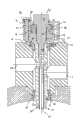
在图3中,示出了根据本发明的优选实施方式的漂移管12、保持元件14、梁(girder)20以及安装机构的立体截面图。与参照图1和2描述的现有技术相比,类似或相同的部件将采用相同的参考标号。图4中示出了该安装机构更详细的截面图。In Fig. 3, a perspective cross-sectional view of the drift tube 12, the holding
在图3的截面图中,示出永久四极磁体53。而且,在图3中尤其在图4中,示出保持元件14和漂移管12中的冷却水通路。具体地,提供可连接至供水系统(未示出)的外部冷却套54,该供水系统将安装在孔22中。在永久四极磁体53周围流动后,冷却水通过中央通道56流回,并通过安装在孔24中的排出管线(未示出)排出。In the sectional view of FIG. 3 , a
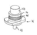
梁20、上部定位环26、下部定位环28和金属密封件30的结构与图2中的类似,因而不再描述。但是,与图2的现有技术安装机构不同的是,图3至图5所示的安装机构包括螺栓58,螺栓58包括头部60和杆部,其中该杆部包括大直径部分62和螺纹部分64。螺纹部分64的直径小于大直径部分62的直径。螺纹部分64被拧进保持元件14的第二端14b中。具体地,螺栓58的螺纹部分64被拧进保持元件14的第二端14b中直至大直径部分62的肩部抵靠在保持元件14的第二端14b的肩部上。The structures of the
此外,提供套管66,套管66具有套在螺栓58的大直径部分62上的套筒部分68以及从套筒部分68向外径向伸出的凸缘部分70。凸缘部分70的下侧处于四个碟形垫圈46堆的顶部表面上。因此,凸缘部分70的下侧适于接收由碟形垫圈46或任何其他类型的适当盘状弹簧所产生的轴向偏置力。Furthermore, a
凸缘部分70的上侧的径向内部部分邻接螺栓58的头部60的下侧。因此,凸缘部分70的上侧适于将碟形垫圈46所产生的轴向偏置力转移至螺栓头60从螺栓58的大直径杆部62伸出的部分上。A radially inner portion of the upper side of the
还应该注意,凸缘部分70的直径大于螺栓头的直径。这样留出了凸缘70的上侧的径向向外部分,以用来与预应力构件72接合,预应力构件72通过连接螺栓74(在图4和5中仅示出了一个)与底部构件76连接。底部构件76包括环形支承表面78,碟形垫圈46堆位于环形支承表面78上。套管66的套筒部分68被插入底部构件76的中央开口79中。It should also be noted that the diameter of the
在连接螺栓74的头部与预应力构件72之间,设有枢转或球形垫圈80。球形垫圈80具有凹球面,在该凹球面中设有具有匹配的凸面的另一垫圈82。在一些应用中,凸面垫圈82可与连接螺栓74的头部成为整体,在现有技术中称为“带凸缘的螺栓头”。与附加垫圈82组合的球形垫圈80或者适当的带凸缘的螺栓头允许对连接螺栓74的纵轴与预应力构件72的上表面之间偏离90°进行补偿。Between the head of the connecting
此外,具有定位销84形式的定位元件与底部构件76和梁20接合,更准确地说,与梁20的上部定位环26接合,从而在底部构件76与梁20之间限定预定的转动方向。Furthermore, positioning elements in the form of positioning pins 84 engage the
接下来,将描述该安装机构的安装方法和功能。Next, the mounting method and function of the mounting mechanism will be described.
在通过保持元件14安装漂移管12前,将碟形垫圈46放置在底部构件76的环形支承表面78上,并将套管66的套筒部分68插入到碟形垫圈46的中心孔和底部构件76的中央开口79中,如图4和5清楚所示。然后,将预应力构件72放置在底部构件76上并将连接螺栓74拧紧,从而压缩并因而对碟形垫圈46预加应力。优选地,利用从下方作用于底部构件76以及从上方作用于套管66上的压力对碟形垫圈46预加应力。这样,就无需对连接螺栓74施加太大的拧紧力。Before mounting the drift tube 12 by the retaining
应该注意,预应力构件72的孔73的直径大于每个碟形垫圈46中的孔的直径,以使仅一部分预应力构件72与碟形垫圈46重叠。然而,由于套管66的凸缘70设置在碟形垫圈46与预应力构件72之间,所以会在碟形垫圈46的整个顶部表面上施加非常均匀的预应力,从而可靠地阻止垫圈46在预应力的作用下倾斜、移位和/或卡住。另外,套管66确保碟形垫圈46将整齐地同轴对齐,这也能阻止垫圈倾斜和卡住。通过紧固连接螺栓74,能够对碟形垫圈46施加预定的预应力。It should be noted that the diameter of the
当通过保持元件14实际安装漂移管12时,将保持元件14插入梁20中,并且将包括底部构件76、预应力构件72、碟形垫圈46以及套管66的被预加应力组件放置在梁20的顶部,其中梁20与底部构件76之间的转动位置被定位销84控制。这样,剩下来要做的是将螺栓58通过孔73插入预应力构件72中并经过套管66的套筒部分68将螺栓的螺纹部分64拧进保持元件14的第二端14b,直至大直径部分的肩部抵靠于保持元件14的第二端14b处的相应肩部。由于碟形垫圈46堆在此时被预压缩,所以在螺栓58的头部60与套管66的凸缘部分70之间仍存在较小空隙。这样,通过目测该空隙能够确认在螺栓的螺纹部分64被完全插入保持元件14,螺栓处于正确位置。应该注意,孔73的直径大于螺栓58的头部60的直径,以便只要释放预应力构件72,头部60就位于凸缘部分70的上侧的径向向内部分上。When the drift tube 12 is actually installed by the retaining
接下来,将连接螺栓74拧松,因此压缩力将从预应力构件72转移至螺栓的头部60。因为凸缘70设置在碟形垫圈46与预应力构件72和螺栓头60之间,所以预应力构件72与螺栓头60之间的这种负荷转移将以非常平滑且受控的方式发生,而不会引起碟形垫圈46的任何相对移动。另外,由于套管的套筒部分,在碟形垫圈46与螺栓58的大直径部分62之间不会存在摩擦或将存在很小的摩擦。替代地,几乎所有的预应偏置力将转变成精确轴向力,其向上拉动保持元件14,直至紧靠于金属密封件30处。由于不存在偏离轴向力,所以保持元件16和漂移管12的位置能够通过上部和下部定位环26、28非常精确地控制。Next, the connecting
在所示的优选实施方式中,碟形垫圈46在未压缩状态下的高度为1.5mm,并且被选择使得约80%的压缩产生的力等于使金属密封件30压缩并使保持元件14精确地抵靠于定位环28所需的力的总和。应该注意,在恢复力的线性范围内,由碟形垫圈堆产生的弹力取决于总压缩路径而非垫圈的数量。所需的碟形垫圈46的数量由其他距离求得,该其他距离是安装处于未压缩状态的金属密封件30加上确保螺栓58的大直径部分62的肩部抵靠保持元件14的第二端14b上所形成的肩部的空隙所需的距离。在具有四个碟形垫圈46的实施方式中,80%的压缩在每个垫圈上留下20%的富余(margin),这样刚刚超过通常为1mm的所需富余。预应力构件72提供预压缩状态下的额外压缩。In the preferred embodiment shown, the
为了充分压缩金属密封件30,在所示的实施方式中,需要约16kN的力。当然,适当的力将取决于金属密封件的形状、加固和所使用的金属的类型。需要约3kN的附加力确保保持元件14正确地抵靠于下部定位环28上。两个力之和需要由碟形垫圈46通过螺栓58施加至保持元件14上。In order to fully compress the
与参照图1和2所讨论的现有技术相比较,可以看出安装变得相当简单,并且部件的数量已极大地减少。尤其是,可通过新设计省略将延长杆36安装在保持元件14处的相当繁复的步骤。Compared with the prior art discussed with reference to Figures 1 and 2, it can be seen that the installation is considerably simpler and the number of parts has been greatly reduced. In particular, the rather complicated step of mounting the
但是,本发明的安装机构不仅构造简单,而且具有更好的性能。发明人注意到通过图2的设计,很难将预应力可靠地转变为保持元件14上的精确轴向拉力。实际上,可以看出图2中的碟形垫圈46与延长杆36之间可能存在相当大的摩擦。由于该摩擦在延长杆36的周向方向上是不均匀的,所以摩擦力会导致危及漂移管12在保持元件14的第一端14a处安装精度的轴偏离力。而且,即使均匀摩擦减少有效的拉力并因而可能导致较差安装。However, the installation mechanism of the present invention is not only simple in structure, but also has better performance. The inventors have noticed that with the design of FIG. 2 it is difficult to reliably convert the prestress into a precise axial tension on the retaining
应该了解,图2中现有技术设计的垫圈46与延长杆36之间的摩擦是因为一些垫圈46未对准而产生的。实际上,不容易通过图2的机构在预应力下将垫圈46精确地对准。It should be understood that the friction between the prior art design of the
与此形成对比,本发明的套管66允许在预应力下将碟形垫圈46精确地对准。此外,通过套管66的套筒部分68阻止碟形垫圈46与螺栓58的杆部之间的任何摩擦。最终,即使可阻止摩擦,但是也应该注意,精确的轴向推力将仅在碟形垫圈46精确地同轴对准的情况下由碟形垫圈46产生。这也可在预加应力过程中以及将预应力从预应力构件72转移至螺栓58的头部60的过程中通过套管66进行确保。实际上,如前所述,由于螺栓头60和预应力构件72均通过同一凸缘部分70接收偏置力,所以从预应力构件72到螺栓头60的负荷转移非常平滑并且从蝶形垫圈的角度来说“未察觉”地发生,从而可避免在松开预应力构件72的情况下垫圈的任何移动。In contrast to this, the
简而言之,根据图3至6所示的优选实施方式的安装机构允许以极少的安装量来产生具有预定且可再现幅值的精确轴向安装力。In short, the mounting mechanism according to the preferred embodiment shown in Figures 3 to 6 allows to generate a precise axial mounting force with a predetermined and reproducible magnitude with very little mounting volume.
虽然使用六个螺栓来紧固图2的预加应力的圆筒48,但是根据优选实施方式仅使用两个连接螺栓74来将预应力构件72紧固至底部构件76。当连接螺栓74之一未拧紧时,预应力构件72将相对于底部构件76稍微倾斜。然而,由于球形垫圈80,所以该移动可被补偿以使连接螺栓不会弯曲。这是对图2的设计的改进,在图2的设计中已发现用于拧紧预加应力的圆筒48的螺栓在操作过程中会弯曲。预应力构件72可通过两个螺栓连接至底部构件76。使用平行且偏移180°的两个扳手(在任一螺栓上使用一个扳手)有助于一致地释放螺栓。虽然人员施加了扭矩,但是因螺栓从中心偏移而作用于预应力构件72和底部构件76上的剩余扭矩被上部定位环26中的定位销84阻挡,从而抑制径向移动。While six bolts are used to fasten the
此外,参照图5,注意预应力构件72具有细长形状,其具有与两个连接螺栓74的连接线对应的较长轴线。当安装机构被应用于梁20上时,定位销84确保以下定向,即预应力构件72的纵轴相对于梁20的延伸方向是横向的。这确保相邻的安装机构不会彼此干扰。Furthermore, referring to FIG. 5 , note that the prestressing
如上所述,该安装机构允许通过所需的精度将漂移管12安装在容器10中。需要对漂移管内磁体沿加速结构进行+/-0.3mm校准以使全部粒子束加速并保持射束损失并因而限制材料辐照。在该+/-0.3mm中,+/-0.1mm是在将加速结构定位在其底部(未示出)上所能够获得的最大精度。另一个+/-0.1mm是磁体内磁中心的容差,从而留下+/-0.1mm的容差用于在加速容器或加速腔内定位漂移管。此外,容器10的直径通常为50cm,因而保持元件14在容器内的悬臂长度加上漂移管直径的一半通常为25cm。由于漂移管12及其保持元件14将从容器10的内部安装,所以漂移管及其保持元件14的最大长度需小于容器10的直径。保持元件14位于上部定位环26与下部定位环28之间的悬臂长度部分通常为容器内悬臂长度的一半,在优选的实施方式中大约为12cm。因此,漂移管12处的+/-0.1mm的定位容差因而转换为在每个定位环26、28处+/-0.02mm的定位容差。该容差不得不实现为定位环26、28的加工容差与细长保持元件14在定位环26、28的高度处的容差之和。所需的加工容差+/-0.01mm处于极限,但利用当前精密加工也可能实现,因而用于在前面所阐述的“调整和组装”方案。As mentioned above, this mounting mechanism allows the drift tube 12 to be mounted in the vessel 10 with the required precision. A +/- 0.3 mm alignment of the magnet inside the drift tube along the accelerating structure is required to accelerate the full particle beam and keep beam loss and thus limit material exposure. Of this +/-0.3 mm, +/-0.1 mm is the maximum accuracy that can be obtained in positioning the accelerating structure on its base (not shown). Another +/-0.1mm is the tolerance of the center of the magnet inside the magnet, thus leaving a +/-0.1mm tolerance for positioning the drift tube within the accelerating vessel or cavity. Furthermore, the diameter of the vessel 10 is typically 50 cm, so the cantilevered length of the retaining
在申请人设计的实施方式中,22个漂移管12被安装在一个2m长的梁20上。该设计的特有优势在于,漂移管在梁20中的精确相对定位可通过在单个加工操作中利用+/-0.01mm的容差精确加工具有梁20中全部漂移管位置的定位环26和28来实现。如果在同一操作中加工梁上的参考表面,则在容器内部的漂移管位置可通过容器外梁上的参考表面而建立。In the embodiment devised by the Applicant, 22 drift tubes 12 are mounted on a 2 m
本发明的安装机构的另一优势在于漂移管可通过相同精度的备用元件来替换而不会损失精确度。在替换操作后无需对测量台进行进一步调整,因此可以在比之前更短的时间内进行漂移管替换。Another advantage of the mounting mechanism of the invention is that the drift tube can be replaced by a spare element of the same precision without loss of precision. No further adjustments to the measuring stand are required after the replacement operation, so drift tube replacement can be performed in a shorter time than before.
另外,通过使用具有大直径部分62和螺纹部分64的螺栓58,作用于被安装状态的保持元件14上的偏置力可通过大直径部分62的长度而预先限定。考虑到漂移管与已事先压缩的密封件30再次组装的情况。由于密封件30的变形通常是至少部分塑性的,根据图2的现有技术组件,密封件的压缩会导致当密封件30被第二次使用时螺母52在延长元件36上的安装位置不同。即,螺母52将在延长元件36上拧紧至比图2的表示更低的位置处。这样,在预压缩被释放后碟形垫圈46的力将高于金属密封件的第一次安装后的力。与此相反,通过本发明的安装机构,即使需再次使用被稍压缩的金属密封件,由于被相对于垫圈46的尺寸的大直径部分的长度所限定,安装状态下的偏置力也将精确地匹配标称偏置力。Furthermore, by using a
虽然已具体地参照将漂移管安装到加速器容器中,对安装机构进行了描述,但是安装机构不限于该具体目的。可替代地,安装机构可有利地应用于任何设备中,其中杠杆臂被加工至需要相对于结构、尤其是相对于真空容器精确定位的精度。这可用于其它类型的应用或者其它领域,尤其在光学领域中。Although the mounting mechanism has been described with specific reference to mounting the drift tube into an accelerator vessel, the mounting mechanism is not limited to this specific purpose. Alternatively, the mounting mechanism may advantageously be applied in any device in which the lever arm is machined to the precision that requires precise positioning relative to the structure, especially relative to the vacuum vessel. This can be used in other types of applications or in other fields, especially in the field of optics.
尽管在附图和上面的说明中详细地示出和描述了优选的示例性实施方式,但是这应该被看作为纯粹的实施例并且不限制本发明。应该注意,在这点上仅示出和描述了优选的示例性实施方式,应该保护现在或将来落入本发明的保护范围内的所有变化和修改。While the preferred exemplary embodiment has been shown and described in detail in the drawings and the foregoing description, this should be considered as purely an example and not as a limitation of the invention. It should be noted that only preferred exemplary embodiments have been shown and described at this point, and all changes and modifications now or in the future that come within the scope of the invention should be protected.
参考标记reference mark
10 容器10 containers
12 漂移管12 drift tube
14 保持元件14 holding element
16 漂移管12中的孔16 hole in drift tube 12
18 进入开口18 Entry opening
20 梁20 beams
22、24 用于冷却水供给/排出的孔22, 24 Holes for cooling water supply/discharge
26 上部定位环26 upper positioning ring
28 下部定位环28 Lower positioning ring
30 金属密封环30 metal sealing ring
32 保持元件14的肩部32 retaining
32b 保持元件14用于轴向定位的肩部
34 保持元件14的纵轴34 The longitudinal axis of the retaining
35 栓元件35 bolt element
36 延长杆36 extension rod
38 半圆元件38 semicircle element
40 颈部40 neck
42 延长杆36的凸缘部分42 The flange part of the
44 螺栓44 bolts
46 蝶形垫圈46 butterfly washer
48 预加应力的圆筒48 prestressed cylinder
48a 预加应力的圆筒48的下部48a The lower part of the
48b 预加应力的圆筒48的上部48b Upper part of
50 孔50 holes
52 螺母52 nuts
53 四极磁体53 quadrupole magnet
54 外部冷却套管54 External cooling jacket
56 中央冷却水通路56 Central cooling water passage
58 螺栓58 bolts
60 螺栓58的头部60 head of
62 大直径部分62 large diameter part
64 螺纹部分64 threaded part
66 套管66 casing
68 套管66的套筒部分68 The sleeve part of
70 套管66的凸缘部分70 The flange part of
72 预应力构件72 Prestressed members
73 预应力构件72的孔73 The hole of the
74 连接螺栓74 Connecting bolts
76 底部构件76 bottom member
78 支承表面78 bearing surface
79 底部构件76的中央开口79 central opening of
80 凹的球形垫圈80 concave spherical washer
82 凸的球形垫圈82 Convex spherical washer
84 定位销84 positioning pin
Claims (13)
Applications Claiming Priority (1)
| Application Number | Priority Date | Filing Date | Title |
|---|---|---|---|
| PCT/EP2010/003031WO2011144222A1 (en) | 2010-05-18 | 2010-05-18 | Mounting mechanism |
Publications (1)
| Publication Number | Publication Date |
|---|---|
| CN102907182Atrue CN102907182A (en) | 2013-01-30 |
Family
ID=43513838
Family Applications (1)
| Application Number | Title | Priority Date | Filing Date |
|---|---|---|---|
| CN2010800667941APendingCN102907182A (en) | 2010-05-18 | 2010-05-18 | Mounting mechanism |
Country Status (7)
| Country | Link |
|---|---|
| US (1) | US9360038B2 (en) |
| EP (1) | EP2572559B1 (en) |
| JP (1) | JP5684373B2 (en) |
| CN (1) | CN102907182A (en) |
| BR (1) | BR112012029306A2 (en) |
| IL (1) | IL223034A0 (en) |
| WO (1) | WO2011144222A1 (en) |
Cited By (2)
| Publication number | Priority date | Publication date | Assignee | Title |
|---|---|---|---|---|
| CN106122017A (en)* | 2015-05-09 | 2016-11-16 | 曼柴油机和涡轮机欧洲股份公司 | Fluid energy machine |
| CN109936909A (en)* | 2019-04-02 | 2019-06-25 | 清华大学 | A fixed structure of drift tube and interdigital drift tube accelerator |
Families Citing this family (3)
| Publication number | Priority date | Publication date | Assignee | Title |
|---|---|---|---|---|
| JP5766646B2 (en)* | 2012-03-28 | 2015-08-19 | 三菱重工業株式会社 | Drift tube type linear accelerator |
| DE102013018241B4 (en)* | 2013-10-30 | 2016-01-14 | Ludwig Ehrhardt Gmbh | Power clamping nut |
| CN109874222B (en)* | 2017-12-06 | 2022-10-25 | 清华大学 | Drift tube, drift tube linear accelerator and drift tube processing method |
Citations (5)
| Publication number | Priority date | Publication date | Assignee | Title |
|---|---|---|---|---|
| US2545595A (en)* | 1947-05-26 | 1951-03-20 | Luis W Alvarez | Linear accelerator |
| US2874326A (en)* | 1957-06-05 | 1959-02-17 | Nicholas C Christofilos | Linear accelerator |
| JPS54111260U (en)* | 1978-01-23 | 1979-08-04 | ||
| DE3842351A1 (en)* | 1988-12-16 | 1990-06-28 | Netter Gmbh | Process and fastening for connecting vibrating objects |
| US5179350A (en)* | 1991-08-07 | 1993-01-12 | Accsys Technology, Inc. | Drift tube linac with drift tube performance normalization and maximization |
Family Cites Families (4)
| Publication number | Priority date | Publication date | Assignee | Title |
|---|---|---|---|---|
| US5619095A (en)* | 1995-02-21 | 1997-04-08 | Hughes Aircraft Company | Projection cathode ray tube having tapered shaft screw target assembly |
| DE10333454B4 (en)* | 2003-07-22 | 2006-07-13 | GSI Gesellschaft für Schwerionenforschung mbH | Drift tube accelerator for accelerating ion packets |
| JP4194105B2 (en)* | 2005-09-26 | 2008-12-10 | 独立行政法人放射線医学総合研究所 | H-mode drift tube linear accelerator and design method thereof |
| WO2009048951A2 (en)* | 2007-10-09 | 2009-04-16 | Philips Solid-State Lighting Solutions | Methods and apparatus for controlling respective load currents of multiple series-connected loads |
- 2010
- 2010-05-18EPEP10721002.3Apatent/EP2572559B1/ennot_activeNot-in-force
- 2010-05-18CNCN2010800667941Apatent/CN102907182A/enactivePending
- 2010-05-18JPJP2013510502Apatent/JP5684373B2/ennot_activeExpired - Fee Related
- 2010-05-18USUS13/698,124patent/US9360038B2/ennot_activeExpired - Fee Related
- 2010-05-18BRBR112012029306Apatent/BR112012029306A2/ennot_activeIP Right Cessation
- 2010-05-18WOPCT/EP2010/003031patent/WO2011144222A1/enactiveApplication Filing
- 2012
- 2012-11-14ILIL223034Apatent/IL223034A0/enunknown
Patent Citations (5)
| Publication number | Priority date | Publication date | Assignee | Title |
|---|---|---|---|---|
| US2545595A (en)* | 1947-05-26 | 1951-03-20 | Luis W Alvarez | Linear accelerator |
| US2874326A (en)* | 1957-06-05 | 1959-02-17 | Nicholas C Christofilos | Linear accelerator |
| JPS54111260U (en)* | 1978-01-23 | 1979-08-04 | ||
| DE3842351A1 (en)* | 1988-12-16 | 1990-06-28 | Netter Gmbh | Process and fastening for connecting vibrating objects |
| US5179350A (en)* | 1991-08-07 | 1993-01-12 | Accsys Technology, Inc. | Drift tube linac with drift tube performance normalization and maximization |
Non-Patent Citations (1)
| Title |
|---|
| S. RAMBERGER等: "DRIFT TUBE LINAC DESIGN AND PROTOTYPING FOR THE CERN LINAC4", 《PROCEEDINGS OF LINAC 08》, 29 September 2008 (2008-09-29)* |
Cited By (5)
| Publication number | Priority date | Publication date | Assignee | Title |
|---|---|---|---|---|
| CN106122017A (en)* | 2015-05-09 | 2016-11-16 | 曼柴油机和涡轮机欧洲股份公司 | Fluid energy machine |
| US10132315B2 (en) | 2015-05-09 | 2018-11-20 | Man Energy Solutions Se | Fluid energy machine |
| CN106122017B (en)* | 2015-05-09 | 2020-01-10 | 曼恩能源方案有限公司 | Fluid energy machine |
| CN109936909A (en)* | 2019-04-02 | 2019-06-25 | 清华大学 | A fixed structure of drift tube and interdigital drift tube accelerator |
| CN109936909B (en)* | 2019-04-02 | 2020-09-04 | 清华大学 | A fixed structure of drift tube and interdigital drift tube accelerator |
Also Published As
| Publication number | Publication date |
|---|---|
| US9360038B2 (en) | 2016-06-07 |
| US20130108391A1 (en) | 2013-05-02 |
| WO2011144222A1 (en) | 2011-11-24 |
| JP2013526763A (en) | 2013-06-24 |
| IL223034A0 (en) | 2013-02-03 |
| BR112012029306A2 (en) | 2019-09-24 |
| JP5684373B2 (en) | 2015-03-11 |
| EP2572559B1 (en) | 2016-05-18 |
| EP2572559A1 (en) | 2013-03-27 |
Similar Documents
| Publication | Publication Date | Title |
|---|---|---|
| CN102907182A (en) | Mounting mechanism | |
| US20240084855A1 (en) | Bushing insertion systems and methods | |
| CN102472412B (en) | Methods and apparatus to load a valve packing | |
| JPH03503984A (en) | Rotatable offset nose assembly to secure fasteners | |
| CN106041503A (en) | Tensioning device for pre-stressing assembly with threaded rod | |
| US20140191149A1 (en) | Clamp ring for welded diaphragms | |
| JP2019513926A (en) | Adjustable mini jack coupler and method of use | |
| US11999034B2 (en) | Systems and methods for inserting and removing bushing assemblies | |
| JP6105050B2 (en) | Guide member used in valve actuator assembly | |
| CN108561690B (en) | Product assembling structure adopting wedge block type flexible auxiliary supporting device | |
| CN102460837A (en) | Terminal having a clamping spring | |
| CN110081080A (en) | The big stroke positioning of three freedom decoupling ultraprecise and exciting device | |
| CN101608655A (en) | A kind of can be fastening fast and the bolt device of dismounting | |
| US20120294673A1 (en) | Angularly adjustable clamp assembly | |
| CN118456353A (en) | Pole tensioning device and method for assembling such a device on a pole | |
| US4428275A (en) | Device for connecting a plunger at its crank end to a connecting rod | |
| KR100777933B1 (en) | Connection between two shaft ends coaxially arranged with the gas shuttle valve of the internal combustion engine and the valve actuator | |
| CN104358813B (en) | A kind of pressure mounting of the spring component and the spring assembly using the press-loading apparatus | |
| CN100549441C (en) | Connection set between bar that is used for reciprocator and crosshead | |
| KR102550952B1 (en) | Single axis eccentric screw pump | |
| EP3591667A1 (en) | Device for fastening a blanket module to a fusion reactor vacuum vessel | |
| CN112780827B (en) | A center elastic coupling | |
| CN206973018U (en) | Spring cylinder and atmospheric valve | |
| CN117028511B (en) | Nut screw pair | |
| CN112447354B (en) | Eccentric positioning device for preventing low temperature shrinkage of superconducting magnets |
Legal Events
| Date | Code | Title | Description |
|---|---|---|---|
| C06 | Publication | ||
| PB01 | Publication | ||
| C10 | Entry into substantive examination | ||
| SE01 | Entry into force of request for substantive examination | ||
| WD01 | Invention patent application deemed withdrawn after publication | ||
| WD01 | Invention patent application deemed withdrawn after publication | Application publication date:20130130 |