CN102904003A - Multiband slot loop antenna apparatus and method - Google Patents
Multiband slot loop antenna apparatus and methodDownload PDFInfo
- Publication number
- CN102904003A CN102904003ACN2012102606500ACN201210260650ACN102904003ACN 102904003 ACN102904003 ACN 102904003ACN 2012102606500 ACN2012102606500 ACN 2012102606500ACN 201210260650 ACN201210260650 ACN 201210260650ACN 102904003 ACN102904003 ACN 102904003A
- Authority
- CN
- China
- Prior art keywords
- radiator
- antenna
- slit
- frequency band
- loop
- Prior art date
- Legal status (The legal status is an assumption and is not a legal conclusion. Google has not performed a legal analysis and makes no representation as to the accuracy of the status listed.)
- Granted
Links
Images


Classifications
- H—ELECTRICITY
- H01—ELECTRIC ELEMENTS
- H01Q—ANTENNAS, i.e. RADIO AERIALS
- H01Q1/00—Details of, or arrangements associated with, antennas
- H01Q1/12—Supports; Mounting means
- H01Q1/22—Supports; Mounting means by structural association with other equipment or articles
- H01Q1/24—Supports; Mounting means by structural association with other equipment or articles with receiving set
- H01Q1/241—Supports; Mounting means by structural association with other equipment or articles with receiving set used in mobile communications, e.g. GSM
- H01Q1/242—Supports; Mounting means by structural association with other equipment or articles with receiving set used in mobile communications, e.g. GSM specially adapted for hand-held use
- H01Q1/243—Supports; Mounting means by structural association with other equipment or articles with receiving set used in mobile communications, e.g. GSM specially adapted for hand-held use with built-in antennas
- H—ELECTRICITY
- H01—ELECTRIC ELEMENTS
- H01Q—ANTENNAS, i.e. RADIO AERIALS
- H01Q5/00—Arrangements for simultaneous operation of antennas on two or more different wavebands, e.g. dual-band or multi-band arrangements
- H01Q5/30—Arrangements for providing operation on different wavebands
- H01Q5/307—Individual or coupled radiating elements, each element being fed in an unspecified way
- H01Q5/342—Individual or coupled radiating elements, each element being fed in an unspecified way for different propagation modes
- H01Q5/357—Individual or coupled radiating elements, each element being fed in an unspecified way for different propagation modes using a single feed point
- H01Q5/364—Creating multiple current paths
- H01Q5/371—Branching current paths
- H—ELECTRICITY
- H01—ELECTRIC ELEMENTS
- H01Q—ANTENNAS, i.e. RADIO AERIALS
- H01Q7/00—Loop antennas with a substantially uniform current distribution around the loop and having a directional radiation pattern in a plane perpendicular to the plane of the loop
- H—ELECTRICITY
- H01—ELECTRIC ELEMENTS
- H01Q—ANTENNAS, i.e. RADIO AERIALS
- H01Q9/00—Electrically-short antennas having dimensions not more than twice the operating wavelength and consisting of conductive active radiating elements
- H01Q9/04—Resonant antennas
- H01Q9/30—Resonant antennas with feed to end of elongated active element, e.g. unipole
Landscapes
- Engineering & Computer Science (AREA)
- Computer Networks & Wireless Communication (AREA)
- Support Of Aerials (AREA)
- Waveguide Aerials (AREA)
Abstract
Description
Priority
The application's case is advocated the priority of No. the 13/190th, 363, the U.S. patent application case with same title submitted on July 25th, 2011, and described U.S. Patent application is all incorporated this paper into way of reference.
Technical field
(for example the present invention relates generally to the supplied for electronic device, wireless device or portable radio device) antenna equipment that uses, and more particularly one exemplary aspect in relate to multiband slit loop or loop aerial and tuning and utilize the method for described multiband slit loop or loop aerial.
Background technology
Inside antenna is the element that sees in most of modern radio devices, described modern radio device for example removable computer, mobile phone, Device, smart mobile phone, personal digital assistant (PDAs) or other personal communicator (personal communication devices; PCDs).Usually, these antenna comprises smooth radiating surface and is parallel to the ground plane of described smooth radiating surface, and described smooth radiating surface and ground plane are connected to each other by short-circuit conductor, to realize the coupling of antenna.Described structure be arranged so that described structure serve as the expectation frequency of operation under resonator.Antenna in this case, uses two or more resonators also being common requirement more than operation in the frequency band (for example, double frequency-band, three frequency bands or four frequency band mobile phones).

Be used for mobile material benefit and high display technology (for example, liquid crystal display (LCD), light-emitting diode (LED) display, Organic Light Emitting Diode (the organic light emitting diodes of power efficiency that uses in exploitation; OLED), thin-film transistor (thin film transistors; TFT) etc. the new development in the process) causes the mobile device take large display as feature to produce in a large number, wherein for example the screen size in the mobile phone is 89mm to 100mm (3.5 inches to 4 inches), and screen size is about 180mm (7 inches) in some panel computers.For realizing optimum performance, usually use display ground plane (or shielding).Modern displays needs the larger ground plane of this class, yet for the wireless antenna operation, these larger ground planes no longer are optimal.Specifically, no longer be the optimal following fact that is based on: ground plane dimensions is being brought into play very important effect at the Antenna Design of the one or more air interfaces that are used for device.As a result, antenna bandwidth is at least to a certain extent owing to the impedance mismatching between antenna radiator and the large ground plane reduces.
In addition, current trends have increased the needs for the thinner mobile communications device with larger display, and described larger display is generally used for user's input (for example, touch-screen).This larger display needs again rigid structure to come the support displays assembly, especially during touch screen operation, supports, so that so that interface is firm and durable, and the movement or the deflection that alleviate display.Usually utilize metal master or metal framework, think that the display in the mobile device provides better support.
Use metal shell/underframe, larger ground plane and the demand of thinner crust of the device is implemented to cause new challenge to radio frequency (RF) antenna.Typical antenna solution (for example, unipole antenna, PIFA antenna) needs the ground clearance zone and apart from the enough height of ground plane, so that effectively operation (typical case of modern portable devices requires) in a plurality of frequency bands.These antenna solution is not suitable for aforementioned thin device with metal shell and/or underframe usually, because separation radiator and the needed vertical range of ground plane are no longer valid.In addition, especially when the needs antenna operated in some frequency bands, the metal master of mobile device served as the RF shielding and makes the antenna performance degradation.
Adopt at present the whole bag of tricks to attempt improving to utilize metal shell and/or underframe than the antenna operation in the thin-pass T unit (the slit loop aerial of for example, describing among the European Patent Publication No EP1858112B1).This enforcement need to be at printed substrate (printed wired board; PWB) make slit near the distributing point place and along the whole height of device in.For the device with larger display, optimal antenna operates the common countermeasure set user interface function of needed slot position (for example, button, roller etc.), so the flexibility of restraint device layout enforcement.
In addition, this metal shell must have in the PCB both sides opening that is in close proximity to slit.For preventing in device, producing the radio-frequency cavity pattern, usually use the metallic walls connection opening.All these steps can increase device complexity and cost, and hinder antenna and desired operation frequency band coupling.
The shake feed antennas of coupling of multi resonant is adopted in another existing enforcement, and the shake feed antennas of coupling of described multi resonant comprises the becket radiant element that is assemblied in around the radio device periphery.(usually in both sides) make some slits in radiator, in order to realize the multiband antenna function; Regrettably, this method increases cost and the complexity of device.Suppose that device users grasps communicator by the edge/side of communicator usually, so this configuration easily is subject to because the antenna detuning that the short circuit that produces when the radiator above user's the hand touch slit causes and the impact of communication failure.In addition, need wider slit (width is generally approximately 3mm) to realize low-frequency band (usually 700MHz to the 960MHz) operation of expecting, and therefore wider slit may cause adverse effect to the aesthstic attractive force of device.
Therefore, the utmost point need to be used for the wireless multi-band antenna solution of (for example) portable radio device, described wireless multi-band antenna solution has less form factor and is suitable for the device periphery, and described wireless multi-band antenna solution provides lower cost and complexity and controlling through improving of antenna resonance is provided.
Summary of the invention
The present invention satisfies needs above by especially a kind of space-efficient multi-frequency band antenna device and tuning and use the method for described multi-frequency band antenna device is provided.
In a first aspect of the present invention, a kind of mobile communications device is disclosed.In one embodiment, device comprises: shell and electronics assembly, and described electronics assembly is contained in fact in the described shell, and described electronics assembly comprises ground plane and at least one feed mouth; And multi-frequency band antenna device.Multi-frequency band antenna device comprises: the first day line structure, and described first day line structure comprises element, and described element is arranged at around the outer periphery of shell in fact; With the second day line structure, described second day line structure comprises several monopole radiator branches.In a variant, the first day line structure is connected to ground plane at least two earth point places, thereby forms virtual part and operation part, and described operation part comprises the slit that is arranged near in the element of shell bottom side; The outer periphery of described virtual part surrounds in fact ground plane; And the outer periphery of operation part is arranged at the outside second day line structure that also surrounds in fact of ground plane.
In another embodiment, mobile device comprises: crust of the device; And antenna, described antenna has outside in fact radiator element, described radiator element has at least one slit, and described at least one slit is arranged to respect to shell in order to minimize because user's grip device between the device operating period causes the possibility of radiator element short circuit between slit.
In a variant of alternate embodiment, radiator element comprises closed in fact loop, and at least one slit comprises single slot, and described single slot is arranged on the bottom margin of crust of the device in fact, and described bottom margin was not normally grasped by the user between the device operating period.
In another variant, radiator element comprises closed in fact loop, and described closed in fact loop is arranged on top, bottom margin and the lateral edge of mobile device shell; And at least one slit comprises single slot, and described single slot is arranged at top or bottom margin any one place among both.
In a second aspect of the present invention, a kind of multi-frequency band antenna device is disclosed.In one embodiment, equipment uses through adjusting for Pertable raido communication device, and equipment comprises: the first day line structure, and described first day line structure comprises element, and described arrangements of components becomes to be arranged at around the outer periphery of crust of the device in fact.In a variant, the first day line structure is connected to the ground plane of device at least two positions, thereby forms virtual part and operation part; And described operation part comprises slit, and described slit is formed in the element, in order to be set near the shell bottom side.
In another variant, the outer periphery of virtual part surrounds in fact ground plane; And the outer periphery of second day line structure is arranged at the outside of ground plane.
In another variant, slit is configured to realize the antenna resonance at least one high frequency band.
In a third aspect of the present invention, a kind of method that operates multi-frequency band antenna device is disclosed.In one embodiment, antenna equipment is for portable radio device and have feed, loop radiator element, and described feed, loop radiator element are arranged at around the neighboring area of crust of the device in fact.The loop radiator element has slit, and described slit is arranged at the in fact bottom margin place of shell, and the ground plane of radio device is arranged at the bottom margin a distance away from the loop radiator element.Method comprises following steps: with the electric feed signal excitation feed that comprises lower frequency components and higher frequency components; At least under upper frequency, cause the strength in the loop radiator element.Slit is configured to realize tuning in lower frequency range of antenna equipment.
In a fourth aspect of the present invention, disclose a kind of user of alleviating and disturb the method for radiation with the impact that receives mobile device.In one embodiment, mobile device is characterised in that preferred user crawl position, and method comprises following steps: with comprising at least signal excitation loop antenna element of first frequency component; The loop radiator element is arranged at around the neighboring area of crust of the device in fact, and generates an electromagnetic field between the slit in being formed at loop antenna element.Slit is positioned at the distally with respect to preferred crawl position, in order to alleviate because the electromagnetic interference that user's crawl causes.
In a fifth aspect of the present invention, a kind of method of tuning multi-frequency band antenna device is disclosed.
Will be by accompanying drawing and the more apparent further feature structure of the present invention of following detailed description, essence of the present invention and various advantage.
Description of drawings
Feature structure of the present invention, target and advantage will become more apparent by the detailed description of hereinafter setting forth in conjunction with all figure, wherein:
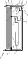
Fig. 1 is the side elevation view of the mobile device of detailed description loop aerial equipment, and described loop aerial equipment configures according to one embodiment of present invention and is installed in the described mobile device.
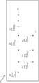
Figure 1A is the vertical view of mobile device of antenna equipment of the embodiment ofpictorial image 1.
Figure 1B is for describing the calcspar of the tuning configuration of multiband loop aerial according to an embodiment of the invention in detail.
Fig. 1 C is the capacity coupled calcspar of the multiband loop aerial of detailed description Fig. 1.
Fig. 2 is for describing the schematic diagram of multiband matching circuit according to an embodiment of the invention in detail.
Fig. 3 is curve chart: (i) measured the free space input return loss; (ii) CTIA v3.1 head, right cheek next door return loss; (iii) CTIA v3.1 head and hand, right cheek next door return loss are measured, and data use the exemplary five frequency-band antenna equipment according to the embodiment configuration of Figure 1A to obtain.
Fig. 4 is curve chart: (i) measured total free space efficient; (ii) efficient on CTIA v3.1 head, right cheek next door; (iii) efficiency measurement on CTIA v3.1 head and hand, right cheek next door, data use the exemplary multi-frequency band antenna device according to the embodiment configuration of Figure 1A to obtain.
Fig. 5 is the curve chart of measuring the free space input return loss of exemplary five frequency-band antenna equipment, and described exemplary five frequency-band antenna equipment configure and comprise the tuning circuit of Fig. 2 according to the embodiment of Figure 1A.
All figure disclosed herein are All rights reserved for Copyright 2011 Pulse Finland Oy.

Embodiment
Referring now to all figure, similar elements symbology similar elements everywhere wherein.
As used herein, term " antenna ", " antenna system ", " antenna assembly " and " multiband antenna " refer to that (but being not limited to) incorporate reception/transmission into and/or propagate any equipment or the system of discrete component, a plurality of element or one or more element arrays of the one or more frequency bands of electromagnetic radiation.Radiation can have numerous types, for example, and microwave, millimeter wave, radio frequency, Digital Modulation, simulation, analog/digital coding, digitally coded millimeter wave energy etc.
As used herein, term " plate " and " substrate " typically refer to (but being not limited to) any smooth in fact or curved surface or assembly, on described surface or assembly other assembly can be set.For instance, substrate can comprise the single or multiple lift printed circuit board (PCB) (for example, FR4), semiconductor chip (die) or wafer and even case surface or other device assembly, and substrate can be rigidity in fact or at least slightly have flexible.
Term " frequency range ", " frequency band " and " frequency domain " refer to that (but being not limited to) is used for any frequency range of signal of communication.These signals can be according to one or more standards or wireless air interface communication.
As used herein, term " mancarried device ", " mobile computing device ", " client terminal device ", " portable computing " and " terminal use's device " includes but not limited to PC (PCs) and microcomputer, no matter is desktop computer, notebook computer or set-top box, personal digital assistant (PDAs), laptop computer, personal communicator, panel computer, the portable navigation auxiliary equipment, the device of J2ME is housed, cellular phone, smart mobile phone, individual's integrated communicaton or entertainment device or photograph letter can install any other device of swap data with network or another.
In addition, as used herein, term " radiator ", " radiating surface " and " radiant element " refer to that (but being not limited to) can serve as that system receives and/or send the element of the part of radio-frequency electromagnetic radiation; For example, the part of antenna or described antenna.
Term " RF feed ", " feed ", " feed-through " and " feeding network " refer to (but being not limited to) any energy conductor and one or more coupling element, described any energy conductor and the transferable energy of one or more coupling element, transforming impedance, the feature of strengthening the property also make impedance property between the I/O RF energy signal meet the impedance property of one or more Connection Elements (for example, radiator).
As used herein, term " loop " and " annular " typically refer to (but being not limited to) closed (or almost closed) path, no matter any shape or size or symmetry.
As used herein, term " top ", " bottom ", " side ", " making progress ", " downwards ", " left side ", " right side " etc. only hint an assembly for relative position or the geometry of another assembly, and never hint the direction of absolute reference coordinate or any needs.For instance, when assembly was mounted to another device (for example, being mounted to the downside of PCB), in fact " top " of assembly part can be present in " bottom " part below.
As used herein, term " wireless " means any wireless signal, data, communication or other interface, described other interface (for example includes, but is not limited to Wi-Fi, bluetooth, 3G, 3GPP, 3GPP2 and UMTS), HSDPA/HSUPA, TDMA, CDMA (for example, IS-95A, WCDMA etc.), FHSS, DSSS, GSM, PAN/802.15, WiMAX (802.16), 802.20, narrow-band/FDMA, OFDM, PCS/DCS, Long Term Evolution (LTE) or advanced LTE (LTE-Advanced; LTE-A), the satellite system of analogue cellular, CDPD, for example GPS, millimeter wave or microwave system, optics, acoustics and infrared ray (that is, IrDA).
General introduction
One significant aspect in, the invention provides the multi-frequency band antenna device for mobile radio apparatus.Antenna equipment advantageously provides compare with the background technology solution complexity that reduces and the antenna performance of cost and improvement.In one embodiment, mobile radio apparatus comprises metal structure (for example, loop or ring), and described metal structure is at least in part around the outer periphery of crust of the device and serve as radiating element of antenna." loop " radiator comprises single narrower slit in one embodiment, and described single narrower slit is arranged in order to minimize because device during use grasps the visual attraction that causes the possibility of radiator short circuit above slit and improve device.
The example embodiment of multi-frequency band antenna device further comprises tuning circuit, and described tuning circuit comprises a plurality of branches, and described a plurality of branches are configured to realize the antenna tuning in the predetermined frequency band separately.The metal loop is grounded to the device ground plane in a plurality of positions, so the electrical length of control antenna.The size of slit is through selecting with optimization the antenna performance in the higher operational frequency bands.Slot position affects low-frequency band lower band resonance frequency, and described resonance frequency is configured to be present in the minimum operation frequency far below the antenna that is used for the radio device normal running.In one approach, come the operation of tuned antenna lower band with the inductor that is connected between feed and the lower band resonant circuit.
Advantageously, the antenna that is coupled to the electronic installation with exemplary antenna disclosed herein is greatly simplified, because only need single feed to connect (although being not limited to single feed).In a particular implementation, be connected to loop element tuning electric current of high frequency band, thereby allow the highest tuning high frequency band resonance and not the visual appearance of modifier or to the device visual appearance cause adverse effect.
In another was implemented, tuned cell was by the electromagnetic field capacitive coupling, and described electromagnetic field is responded to above the non-conductive gap between tuning and the loop radiator.
Also disclose tuning and method operational antennas equipment.
The detailed description of example embodiment
The variant of detailed description and equipment of the present invention and the method for various embodiment is provided now.Although mainly discuss in the background of mobile device, various device and method that this paper discusses are not restricted to this.In fact, the complex antenna that the many equipment in equipment as herein described and the method and method can be used for any number, no matter described complex antenna is associated with mobile device or the device of fixture, honeycomb fashion or other type.
Exemplary antenna equipment
Referring now to Fig. 1 to Fig. 2, describe the example embodiment of radio antenna apparatus of the present invention in detail.An example embodiment for the antenna equipment of mobile radio apparatus is presented among Fig. 1, and described Fig. 1 illustrates the side elevation view of host mobility device 100.Device 100 comprisesdisplay module 104 andcorresponding ground plane 106, and describedground plane 106 is arranged in the middle of two dielectric cap 102,103.In a variant, adielectric cap 103 in thedielectric cap 103 comprises opening, and described opening is corresponding to the display periphery, in order to allow (for example) touch-screen or other interactive function.Yet, the touch-screen display thatdisplay 104 can be including (for example) the only display unit that is configured to only show information, allow the user to provide inputs to the input in the device by display 104 (for example, or other technology capacitive or other technology).Display 104 can be including (for example) liquid crystal display (LCD), light-emitting diode (LED) display, LED-LCD display, Organic Light Emitting Diode (OLED) display or based on the device of TFT.It will be apparent to those skilled in the art that method of the present invention is applicable to any following Display Technique comparably, as long as display module and device and antenna configuration (device of for example, describing among Fig. 1 to Fig. 2 and antenna configuration) are substantially mechanically compatible.
Metal loop orencircle 110 and be arranged at the in fact outer periphery place of crust of the device, as shown in fig. 1.The loop configuration of the present embodiment provides mechanical rigid, structural intergrity and strengthens aesthstic attractive force for device.In a variant (not shown), replacering 110 with metal segments (for example, the part of loop), described metal segments is around the part of device periphery.
Can use thering 110 of anymethod shop drawings 1 in the various appropriate methodologies, described method comprises (for example) metal casting, pressed part, bonding jumper or is arranged at conductive coating on the non-conductive carrier (for example, plastics).
Figure 1A is the plan view from above of the exemplary antenna structure of the embodiment of detailed description Fig. 1.Ring 110 in a plurality of positions 116,117,119 places are connected to ground plane 106.In addition, the top section of ring is attached to ground plane alongtop perimeter structure 115.
Earthpoint 116,earth point 117 is used for antenna tuning, and the position of describedearth point 116,earth point 117 is defined the length of annular or loop antenna operation part (that is, the part of antenna transmission/reception RF radiation) effectively.Earthpoint 115,earth point 119 are preferably minute at a certain distance, and described distance is less than the quarter-wave (under the highest frequency of operation) of antenna.In a variant,ground structure 115 is configured to the major part of the top edge of cover ring, as shown in Figure 1A.In another variant (not shown),earth point 115 makes the partial earthing at top loop edge.
Ring top part (that is, coming mark takeearth point 116,earth point 117,earth point 119,earth point 115 as boundary and by thedashed rectangle 112 among Figure 1A) forms ground connection (or virtual) part.The virtual-antenna partial configuration becomes to be in the electromotive force identical with the electromotive force of ground plane.This arrangement minimises is divided the unwanted antenna RF radiation of emission from antenna grounding portion, and further reduces antenna to because the user grasps short circuit that mobile device causes and the susceptibility of load effect during operation.In a variant, can remove on demand the top loop part by shell design, to simplify assembly and to reduce the cost of radio device.In another variant, ring is in order to generator support structure and visual attraction.
In brief, the antenna of embodiment shown in Fig. 1 to Figure 1A is configured to operate in low frequency and high frequency (relative to each other) opereating specification.In a variant, low operational frequency range is between about 800MHz and approximately between the 960MHz, and high operational frequency range is between approximately between 1700MHz and the 2200MHz.One of skill in the art will appreciate that, above frequency limit is exemplary, and above frequency limit can be carried out up to another from one based on concrete designing requirement and parameter (for example, the target country of antenna size, device operation etc.) and change between implementing.Usually, each operational frequency range in the operational frequency range can be supported the one or more different frequency band according to specification (for example, LTE/LTE-A or the GSM) configuration of the relevant wireless application system of management.This paper can support one or two lower band (LFB1, LFB2) and at least three high frequency band (UFB1, UFB2, UFB3) about an antenna embodiment of Figure 1A diagram and description.In another embodiment, high-frequency operation scope (for example, between about 2500MHz and approximately between the 2700MHz) is in order to realize the antenna operation in the 4th high frequency band (UFB4).
Return now Figure 1A, the base section of loop or loop configuration (being arranged atvirtual part 112 belows) forms the operating structure of antenna radiator, and is called as annular or line loop part at thispaper.An earth point 116 is determined the electrical length of operation part in high-frequency range, and the antenna electrical length that anotherearth point 117 is determined in the low-frequency range.Thering 110 of the present embodiment comprisesnarrower slit 114, and describednarrower slit 114 is along the bottom margin setting of host apparatus, and thering 110 of the present embodiment is configured to realize the antenna tuning in the high-frequency range.In a variant, the width of slit is about 0.8mm, but can be depending on the performance of expectation and physical attribute and use other value.For the aesthstic attractive force of holdout device and increase the structural intergrity of shell, available dielectric substance (for example, plastics) is filled slit.
In addition, the present invention expects use: (i) have and change or the slit of non-constant width (that is: the diverse location place groove width on whole ring thickness is different); (ii) use two or more slits.
In the embodiment of Figure 1A,ground plane 106 is apart from the bottom margin interval predetermineddistance 118 ofring 110; For example, about 13mm.The device without groundconnection base section 108 containing antenna tuning structures 120.Tuning structure 120 is configured to realize operation when antenna is in the low operational frequency bands ofportable radio device 100 and higher operationalfrequency bands.Structure 120 is coupled to the feed electronic installation at distributingpoint 138 places, andstructure 120 comprises some tuning branches 122,124,128,130.
Antenna frequencies in the following realization illustrated embodiment is tuning: the antenna tuning that tuningbranch 124 realizes in the first lower band (LFB1), described LFB1 is corresponding to antenna low-frequency resonant f1In a variant, LFB1 comprises the frequency band from 824MHz to 894MHz, and f1Centered by about 850MHz (being also referred to as the 850MHz frequency band).In another variant, LFB1 comprises the frequency band from 880MHz to 960MHz, and f1Centered by about 900MHz (being also referred to as the 900MHz frequency band).
In the variant of the embodiment of Figure 1A, series-tunedcircuit 136 is arranged between the horizontal component offeed 136 and branch 124.Tuning circuit 136 is configured to adjust the electrical length of lower frequency antenna resonance device and increases antenna operation frequency range in the lower band.The lower frequency bandwidth of this increase realizes the antenna operation among two lower band LFB1, the LFB2.
In one embodiment, tuningcircuit 136 comprises coil, and described coil is configured to provide the approximately series inductance of 10 nanohenrys (nH) toradiator branches 124, and wherein LFB1 is the 850MHz frequency band, and LFB2 is the 900MHz frequency band.Those skilled in the art will appreciate that other tuned cell enforcement is applicable to the present invention comparably, described other tuned cell implements to include but not limited to discrete inductor, capacity cell or above-mentioned combination.
The antenna operation of embodiment shown in Figure 1A in LFB1 (and LFB2) frequency band comes tuning by the entire length ofresonator 124 and the reactance value oftuned cell 136.
Thelong section 126 of loop configuration base section (being formed betweenearth point 117 and the slit 114) is in frequency f0Lower formation resonance.For the low-frequency resonant of under lower frequency (for example, LFB1, LFB2), realizing the antenna operation of expectation and preventing from being coupled, with f0Resonance is tuned to and is lower than the low operational frequency range (for example, 820MHz to 960MHz) of antenna.In a variant, select base section resonance frequency f at about 600MHz place0
Antenna high-frequency operation scope forms by at least two high-frequency resonants, and described at least two high-frequency resonants are hereinafter referred to as f2Resonance and f3Resonance.The first high-frequency resonant (f2) form by theshorter part 127 ofring 110, describedring 110 is formed betweenslit 114 and the earth point 116.In the embodiment shown, the antenna tuning of this resonance is realized by the length that changes tuningbranch 130 discal patch.Be coupled toring 110, as hereinafter describing in detail about Figure 1B to Fig. 1C tuning branch 130 electric current ground or electric capacity.
Directly fed antenna high-frequency tuning structure 128 is configured at the second high-frequency resonant (f3) the lower resonance that forms.In the embodiment shown, f3The value of resonance is come tuning by the length (with the degree of thetuning branch 128 approaching base sections that encircle) of tuning branch 128.f2Resonance and f3Each of humorous center of percussion can be configured to provide the antenna function in the one or more high frequency band.
In a variant, f2Resonance frequency band and f3The composite crossover of resonance frequency band is from the about frequency range of 1710MHz to 2170MHz, therefore allows to meet the device operation in the following high frequency band of system of LTE: 1710MHz to 1880MHz, the 1850MHz to 1990MHz and the 1930MHz to 2170MHz that correspond respectively to UFB1 to UFB3.
In another embodiment, use direct feed low-frequencyrange irradiation structures 122 in conjunction with tuningbranch 124, form low-frequency range frequency component be called f4The harmonic resonance of resonance, thus realize antenna operation in the 4th high frequency band (UFB4).The value of UFB4 is come tuning by the length of thehorizontal branch 122 of C shape structure (having two turnings), described C shape structure is formed by tuningbranch 122, the tuningbranch 124 of Figure 1A.
Referring now to Figure 1B to Fig. 1 C, two example embodiment of diagram and description antenna tuning structure.Theantenna tuning structure 120 of Figure 1B is corresponding to the antenna embodiment of Figure 1A and comprise f2Tuning branch 130, described f2Tuning branch 130 is connected directly toloop configuration 110 at point 139 places.
In another embodiment (shown in Fig. 1 C), the tuningbranch 142 of tuningstructure 140 comprises two vertical bars 145,146 andloop structure 144, and describedloop structure 144 is arranged between described two vertical bars 145,146.Vertical bar 146 isearth point 148 place's groundconnection.Tuning branch 142 andring 110 electrical isolation.In a variant, isolation realizes by the thin layer of the dielectric substance that the inner surface alongring 110arranges.Tuning branch 142 by electric field electric capacity be coupled to thering 110, described electric field is responded to abovenon-conductive gap 150, non-conductive gap 152.In one embodiment, the width in gap is chosen to be approximately 0.3mm, but can equally successfully use other value.
In capacitive coupling arranged, the dielectric gap between the operation part of tuning and becket needed sufficiently little, in order to form gap resonance more than the highest frequency of operation of antenna.Tuning tap capacitance is coupled to loop configuration does not need tuning structure to any physical attachment (for example, soldering, welding) of ring, therefore advantageously helps the antenna manufacturing and allows the material of relative broad range to select.
Gap betweenloop section 127 and thetuning branch 142 since between the surface of the surface ofloop section 127 and tuningbranch 142 than highfield, and under certain frequency, causing gap resonance, described frequency is defined by the electric capacity between the surface of the surface ofloop section 127 and tuning branch 142.Reduce the gap and produce more close-coupled between these elements, and reduce the gap and make the gap resonance frequency become higher and surpass the antenna operation frequency band.The gap resonance frequency further is subject to the impact of the size in overlapped surfaces zone (being also referred to as coupling regime) betweenbar 144, bar 146 and theloop section 127 of tuning branch 142.Larger coupling regime allows larger gap.
In another embodiment (not shown), multiband antenna is configured to not have tunedcell 136, thereby forms 4 frequency band resonators with single lower band LFB1 and three high frequency band (UFB1, UFB2, UFB3).
In another aspect of the present invention, antenna structure (for example, antenna structure shown in Figure 1A) is equipped with tuning network, so that the optimization antenna performance; For example, increase antenna efficiency and reduce loss.Fig. 2 illustrates an embodiment of this tuning network, and described tuning network is configured to operate in four or more frequency band, is certainly approximately to operate in the frequency range of 800kHz to 2700MHz herein.Network 200 comprises input port 202, and described input port 202 is characterised in that nominal impedance is 50 ohm, and described input port 202 is connected to the feed mouth of portable electron device.Circuit ground point 216 is connected to the device ground plane, and circuit delivery outlet 214 is connected to the aerial radiation structure, for example, and the distributing point 138 among Figure 1A.Inductance element 204 and capacity cell 206 forms the first resonant circuits (L2C2), and described L2C2 is configured to realize the antenna tuning in LFB2 frequency band and the UFB4 frequency band.The exemplary values of capacity cell 206, capacity cell 208, capacity cell 210 and inductance element 204, inductance element 212 as shown in Figure 2.Impedance transformation between the first inductance element 212 and the first capacity cell 208 control antenna radiators and the L2C2 circuit.The second capacity cell 210 is used for tuning purpose, and can omit in some implementations the second capacity cell 210 when needed.Will be appreciated that the configuration of accurate components values and/or tuning network is based on concrete application and parameter request is selected, and accurate components values and/or tuning network configuration can be applied to Another application from one and change, in the situation that given present disclosure, the technical staff of electronic applications is easier to determine these values.
Performance
Fig. 3 to Fig. 5 is provided at by the assignee according to one embodiment of present invention the exemplary antenna equipment simulating of structure and the results of property that test period obtains.
Fig. 3 diagram is as the curve chart of the free space return loss S11 (in dB) of the function of frequency, and described free space return loss S11 measures with the four frequency band multiband antennas that are similar to the structure of embodiment shown in Figure 1A.Four frequency bands of antenna comprise lower band and three high frequency band (1710MHz to 1880MHz, 1850MHz to 1990MHz and 1930MHz to 2170MHz) of a 900MHz.In Fig. 3 with the boundary of the solid marks lower band of identifier 302 appointments, and with the boundary of wire tag 1710MHz and the high-frequency range between the 2170MHz of identifier 304 appointments.With identifier 306 to the curve of identifier 310 marks corresponding to the measurement that in the lower device configuration, obtains: (i) the first curve 306 is taken from the free space; (ii) the second curve 308 is taken from the measurement configuration next door of head, right cheek (BHR) according to CTIA v3.1; (iii) the 3rd curve 310 is taken from by the measurement configuration of head and hand, right cheek (BHHR) according to CTIA v3.1.The data that are presented among Fig. 3 show, comprise along the exemplary antenna of the single less slit of bottom of device location advantageously not because the existence of user's hand and off band detuning, and keep 6dB return loss in whole BHHR measures.
Fig. 4 present with the antenna identical with the antenna of above describing about Fig. 3 measure the relevant data of free space efficient.The efficient (in dB) of antenna is defined as the decimal logarithm of the ratio of radiant power and input power:

The efficient of zero (0) dB is corresponding to desirable theoretical radiator, and wherein all input powers are with the form radiation of electromagnetic energy.
Among Fig. 4 withidentifier 402 to the curve ofidentifier 412 marks corresponding to the measurement that in the lower device configuration, obtains: (i) curve 402,curve 408 are taken from the free space; (ii)curve 404,curve 410 are taken from the measurement configuration next door of head, right cheek (BHR) according to CTIA v3.1; (iii) curve 406-412 takes from by the measurement configuration of head and hand, right cheek (BHHR) according to CTIA v3.1.Data among Fig. 4 show, according to the antenna embodiment of principles of construction of the present invention and be not easy to be subject to because user's hand and head approach the impact of the higher losses that causes, thereby allow the firm operation of radio device.
Fig. 5 diagram is as the curve chart of the free space return loss S11 (in dB) of the function of frequency, described free space return loss S11 obtains for five frequency band multiband antennas according to the structure of embodiment shown in Figure 1A, and utilizes the tuning circuit of the embodiment of this paper Fig. 2.The antenna frequency band comprises 850MHz and 900MHz (two lower bands) and 1710MHz to 1880MHz, 1850MHz to 1990MHz and 1930MHz to 2170MHz (three high frequency band).Lower (824MHz) degree of identifier 502, identifier 504 mark lower frequency ranges and higher (960MHz) degree, and lower (1710MHz) degree and higher (2170MHz) degree of identifier 506, identifier 508 difference mark lower frequency range.Curve with identifier 512 is corresponding to the measurement response of 4 frequency-band antennas of above describing about Fig. 3.Illustrate the antenna response ofmatch circuit 200 simulations of the embodiment that uses Fig. 2 with the curve of identifier 510 marks.The measurement scattering parameter (s-parameter) ofcircuit 200 is used for analog response 510.
The antenna bandwidth in the lower frequency ranges of response 510 that comparison shows that between two antenna responses 510,512 increases, and this antenna bandwidth increases the antenna operation that allows in 850MHz and the 900MHz lower band.
The data that are presented among Fig. 3 to Fig. 5 show, the loop or the loop aerial that dispose narrower slit can operate in wide frequency ranges; That is, cover from the lower band of 824MHz to 960MHz and from the high frequency band of 1710MHz to 2170MHz.This ability advantageously allows to operate portable computing with individual antenna in some mobile frequency bands, described some mobile frequency bands for example, GSM850, GSM900, GSM1900, GSM1800, PCS-1900 and LTE/LTE-A and/or WiMAX (IEEE Std.802.16) frequency band.In addition, use independent tuning branch to allow to form higher-order antenna resonance, therefore allow the antenna operation in the extra high frequency band (for example, 2500MHz to 2600MHz frequency band).This ability further extends to Wi-Fi (802.11) and extra LTE/LTE-A frequency band with the purposes of antenna.Those skilled in the art will appreciate that can revise on demand above given frequency band according to one or more application-specific forms, and can support/use extra frequency band.
Advantageously, slit loop or loop aerial configuration (configuration in the illustrated embodiment as described herein) further allow except the width and diversity of aforementioned operation frequency band, improve the device operation by reducing because the user grasps the possibility that causes antenna short circuit (with the seondary effect that is associated).In addition, gap bottom use is placed on (for example, less single gap shown in this paper example embodiment) improves the aesthstic attractive force of device, because bottom of device is seldom seen during use and described gap reduces needs for non-conductive cladding element or ornamental cladding element (usually needing) in the background technology solution, thereby also can reduce installation cost.
Although it should be understood that according to the concrete order of the step of method and described some aspect of the present invention, these descriptions only are the explanation than broad method of the present invention, and can revise on demand these descriptions according to application-specific.In some cases can some step of unnecessary proposition or some step optional.In addition, can add some step or function to the disclosed embodiments, or change the execution sequence of two or more steps.All these variations are considered as being encompassed in the open and invention of advocating of this paper.
Although above detailed description shows, describes and points out that the present invention is applied to the novel feature structure of various embodiment, but should be understood that those skilled in the art without departing from the invention can to illustrated in device or the form of technique and details carry out various omissions, substitute and change.Above be described as the at present execution optimal mode of the present invention of expection.This description never means restrictive, and should be considered as the explanation of General Principle of the present invention.Scope of the present invention should be determined with reference to claims.
Claims (30)
1. multi-frequency band antenna device for Pertable raido communication device, described antenna equipment comprises:
The first day line structure, described first day line structure comprises the radiator member, and described radiator member is configured to be arranged at around the outer periphery of crust of the device in fact;
Wherein said radiator member comprises slit, and described slit is arranged to respect to described shell in order to minimize because the user grasps the possibility that described crust of the device causes the short circuit between described slit of described radiator member.
2. antenna equipment as claimed in claim 1, wherein:
Described first day line structure is connected to the ground plane of described device at least two positions, thereby forms virtual part and operation part; And
Described operation part comprises described slit, and described slit is formed in the described radiator member, in order to be set to the bottom side near described shell.
3. antenna equipment as claimed in claim 1, wherein said slit are configured to realize the antenna resonance at least one high frequency band.
4. antenna equipment as claimed in claim 1, described antenna equipment further comprises the second day line structure, and described second day line structure comprises several monopole radiator branches, and wherein said several monopole radiator branches comprise:
The first radiator branches, described the first radiator branches is electric to be coupled to the feed mouth of described device and to be configured to operate in the first high frequency band;
The second radiator branches, described the second radiator branches are coupled to the described feed mouth of described device and are configured to operate in the second high frequency band; With
The 3rd radiator branches, described the 3rd radiator branches is electric to be coupled to the described feed mouth of described device and to be configured to operate in the first lower band.
5. antenna equipment as claimed in claim 4, wherein:
The outer periphery of described virtual part surrounds in fact described ground plane; And
The outer periphery of described second day line structure is arranged at the outside of described ground plane.
6. antenna equipment as claimed in claim 4, described antenna equipment further comprises reactance circuit, and described reactance circuit is coupled between described the 3rd radiator branches and the described feed mouth.
7. antenna equipment as claimed in claim 6, wherein said reactance circuit comprise (i) inductance element and/or (ii) at least one in the capacity cell.
8. antenna equipment as claimed in claim 6, wherein the second reactance circuit is configured to adjust the electrical length of described the 3rd radiator branches.
9. antenna equipment as claimed in claim 6, wherein said the first lower band comprises the GSM frequency band, and described the first high frequency band and described the second high frequency band are selected from the group that is comprised of 1700MHz frequency band, 2100MHz frequency band and 2500MHz frequency band.
10. antenna equipment as claimed in claim 4, wherein said slit is set to the lower corners near described crust of the device.
11. antenna equipment as claimed in claim 2, wherein said at least two positions are configured to affect the electrical length of described radiator member.
12. antenna equipment as claimed in claim 11, wherein said at least two positions comprise: (i) the first ground structure, described the first ground structure are arranged on the first side of described radiator member; (ii) the second ground structure, described the second ground structure is arranged on the second side of described radiator member, described the second side is relative with described the first side, so that described the first ground structure and described the second ground structure are configured in the distally of described slit.
13. antenna equipment as claimed in claim 1, the part of wherein said element are set near described bottom side and along in fact lateral extent and the described ground plane interval of described bottom side.
14. a mobile device, described mobile device comprises:
Crust of the device; With
Antenna, described antenna has outside in fact radiator element, described radiator element has at least one slit, described at least one slit with respect to described shell setting so as to minimize since the user described device between the operating period grip device cause the possibility of radiator element short circuit between described slit.
15. mobile device as claimed in claim 14, wherein said radiator element comprises closed in fact loop, and described at least one slit comprises single slot, described single slot is arranged on the bottom margin of described shell of described in fact device, and described bottom margin was not normally grasped by described user between the described operating period of described device.
16. mobile device as claimed in claim 14, wherein:
Described radiator element comprises closed in fact loop, and described closed in fact loop is arranged on top, bottom margin and the lateral edge of the described shell of described mobile device; And
Described at least one slit comprises single slot, and described single slot is arranged at described top or described bottom margin any one place among both.
17. mobile device as claimed in claim 14, wherein:
Described radiator element comprises the first structure, and described the first structure is connected to the ground plane of described device at least two positions, in order to form virtual part and operation part; And
Described slit is arranged in the described operation part on the bottom side of described crust of the device.
18. mobile device as claimed in claim 17, wherein:
Described radiator element further comprises radiator structure, and described radiator structure comprises several monopole radiator branches.
19. mobile device as claimed in claim 18, the outer periphery of wherein said operation part are arranged at the outside of described ground plane and surround in fact described radiator structure.
20. mobile device as claimed in claim 18, wherein said several monopole radiator branches comprise:
The first radiator branches, described the first radiator branches is electric to be coupled to the feed mouth of described device and to be configured to operate in the first frequency band;
The second radiator branches, described the second radiator branches are coupled to the described feed mouth of described device and are configured to operate in the second frequency band; With
The 3rd radiator branches, described the 3rd radiator branches is electric to be coupled to the described feed mouth of described device and to be configured to operate in the 3rd frequency band.
21. mobile device as claimed in claim 20, each the monopole radiator branch in described several monopole radiator branches comprises bus, and described bus has at least one turning.
22. mobile device as claimed in claim 21, at least a portion of wherein said at least one formation C shape structure of turning.
23. mobile device as claimed in claim 20, wherein said the 3rd radiator branches further is configured to operate in the 4th frequency band, and described the 4th frequency band has resonance, and described resonance is near the harmonic wave of the resonance of described the 3rd frequency band.
24. mobile device as claimed in claim 20, wherein:
Described radiator element comprises closed in fact loop; And
The electric described loop that is coupled near described slit of described the second radiator branches.
25. mobile device as claimed in claim 20, wherein:
Described radiator element comprises closed in fact loop element; And
Described the second radiator branches is electromagnetically coupled to the described loop element near described slit above non-conductive gap.
26. mobile device as claimed in claim 14, wherein said radiator element comprise closed in fact loop, described loop forms single continuous structure.
27. a mobile communications device, described mobile communications device comprises:
Shell and electronics assembly, described electronics assembly is contained in fact in the described shell, and described electronics assembly comprises ground plane and at least one feed mouth; With
Multi-frequency band antenna device, described multi-frequency band antenna device comprises:
The first day line structure, described first day line structure comprises element, and described element is arranged at around the outer periphery of described in fact shell; With
The second day line structure, described second day line structure comprises several monopole radiator branches;
Wherein:
Described first day line structure is connected to described ground plane at least two earth point places, thereby forms virtual part and operation part, and described operation part comprises the slit that is arranged near in the described element of the bottom side of described shell;
The outer periphery of described virtual part surrounds in fact described ground plane; And
The outer periphery of described operation part is arranged at the outside of described ground plane and surrounds in fact described second day line structure.
28. method that operates for the multi-frequency band antenna device of portable radio device, described equipment has feed, loop radiator element, described feed, loop radiator element are arranged at around the neighboring area of shell of described in fact device, described loop radiator element has slit, described slit is arranged at the bottom margin place of described in fact shell, and the ground plane of described radio device is arranged at the bottom margin a distance away from described loop radiator element, and described method comprises following steps:
Encourage described feed with the electric feed signal that comprises lower frequency components and higher frequency components; At least under described upper frequency, cause the strength in the described loop radiator element;
Wherein, described slit is configured to realize tuning under described upper frequency of described antenna equipment.
29. one kind alleviates the user and disturbs the method for radiation with the impact that receives mobile device, described mobile device is characterised in that preferred user crawl position, and described method comprises following steps:
With comprising at least signal excitation loop antenna element of first frequency component; Described loop antenna element is arranged at around the neighboring area of shell of described in fact device, and
Generate an electromagnetic field between the slit in being formed at described loop antenna element;
Wherein said slit is positioned at the distally with respect to described preferred crawl position, in order to alleviate because the electromagnetic interference that described user's described crawl causes.
30. the multi-frequency band antenna device for Pertable raido communication device, described antenna equipment comprises:
The first day line structure, described first day line structure comprises radiator element, and described radiator element is configured to be arranged in fact around the outer periphery of crust of the device;
Wherein said radiator element comprises slit, and described slit comprises be used to minimizing because the user grasps the member of radiator element short circuit between described slit that described crust of the device causes.
Applications Claiming Priority (2)
| Application Number | Priority Date | Filing Date | Title |
|---|---|---|---|
| US13/190,363 | 2011-07-25 | ||
| US13/190,363US9450291B2 (en) | 2011-07-25 | 2011-07-25 | Multiband slot loop antenna apparatus and methods |
Publications (2)
| Publication Number | Publication Date |
|---|---|
| CN102904003Atrue CN102904003A (en) | 2013-01-30 |
| CN102904003B CN102904003B (en) | 2017-07-07 |
Family
ID=47071063
Family Applications (1)
| Application Number | Title | Priority Date | Filing Date |
|---|---|---|---|
| CN201210260650.0AActiveCN102904003B (en) | 2011-07-25 | 2012-07-25 | Multiband slot loop antenna apparatus and method |
Country Status (5)
| Country | Link |
|---|---|
| US (1) | US9450291B2 (en) |
| EP (1) | EP2562870B1 (en) |
| KR (1) | KR101558648B1 (en) |
| CN (1) | CN102904003B (en) |
| TW (1) | TWI518998B (en) |
Cited By (14)
| Publication number | Priority date | Publication date | Assignee | Title |
|---|---|---|---|---|
| CN104600440A (en)* | 2015-01-09 | 2015-05-06 | 深圳市中兴移动通信有限公司 | Mobile terminal and antenna structure thereof |
| WO2015117483A1 (en)* | 2014-08-21 | 2015-08-13 | 中兴通讯股份有限公司 | Antenna system |
| CN105009362A (en)* | 2013-03-15 | 2015-10-28 | 高通股份有限公司 | Multipurpose antenna |
| CN105449335A (en)* | 2014-08-20 | 2016-03-30 | 联想(北京)有限公司 | Electronic device |
| CN105789882A (en)* | 2014-12-26 | 2016-07-20 | 比亚迪股份有限公司 | Mobile terminal and antenna of same |
| CN106159440A (en)* | 2015-03-31 | 2016-11-23 | 比亚迪股份有限公司 | Antenna and the mobile terminal with it |
| WO2016183777A1 (en)* | 2015-05-18 | 2016-11-24 | 华为技术有限公司 | Antenna device and terminal |
| CN106329095A (en)* | 2015-06-29 | 2017-01-11 | 比亚迪股份有限公司 | Antenna for mobile phone and mobile phone with antenna |
| CN110416744A (en)* | 2019-07-08 | 2019-11-05 | 维沃移动通信有限公司 | Antenna device, antenna control method and terminal equipment |
| CN110537080A (en)* | 2017-01-05 | 2019-12-03 | 芬兰帕斯有限公司 | Using the antenna assembly of public utilities route and use and manufacturing method |
| CN111613904A (en)* | 2015-03-05 | 2020-09-01 | 集美塔公司 | Aperture Segmentation of Cylindrical Feed Antennas |
| WO2022166444A1 (en)* | 2021-02-08 | 2022-08-11 | 华为技术有限公司 | Antenna and terminal device |
| CN115176384A (en)* | 2020-02-25 | 2022-10-11 | 微软技术许可有限责任公司 | Hybrid cavity mode antenna |
| CN115275583A (en)* | 2022-09-23 | 2022-11-01 | 盛纬伦(深圳)通信技术有限公司 | Broadband multi-beam antenna array element and array applied to decimeter wave frequency band vehicle-mounted communication |
Families Citing this family (37)
| Publication number | Priority date | Publication date | Assignee | Title |
|---|---|---|---|---|
| US9300033B2 (en) | 2011-10-21 | 2016-03-29 | Futurewei Technologies, Inc. | Wireless communication device with an antenna adjacent to an edge of the device |
| US8723739B2 (en)* | 2012-05-11 | 2014-05-13 | Perfect Wireless (Taiwan) Technology Co., Ltd. | Multi-frequency antenna |
| US9444130B2 (en) | 2013-04-10 | 2016-09-13 | Apple Inc. | Antenna system with return path tuning and loop element |
| US9825352B2 (en) | 2013-06-20 | 2017-11-21 | Sony Mobile Communications Inc. | Wireless electronic devices including a feed structure connected to a plurality of antennas |
| GB2516304A (en)* | 2013-07-19 | 2015-01-21 | Nokia Corp | Apparatus and methods for wireless communication |
| EP3032646B1 (en) | 2013-08-06 | 2018-10-10 | LG Electronics Inc. | Antenna device and mobile terminal having same |
| US9660326B2 (en)* | 2014-01-22 | 2017-05-23 | Galtronics Corporation, Ltd. | Conductive loop antennas |
| WO2015166345A2 (en)* | 2014-03-31 | 2015-11-05 | Galtronics Corporation Ltd. | Wearable device antennas |
| KR102151056B1 (en)* | 2014-04-09 | 2020-09-02 | 삼성전자주식회사 | Antenna and Electronic Devices comprising the Same |
| US9608310B2 (en)* | 2014-05-23 | 2017-03-28 | Nokia Technologies Oy | Apparatus having a conductive housing and an antenna with tunable resonance |
| US10381875B2 (en) | 2014-07-07 | 2019-08-13 | Qualcomm Incorporated | Wireless power transfer through a metal object |
| US10622702B2 (en)* | 2014-12-26 | 2020-04-14 | Byd Company Limited | Mobile terminal and antenna of mobile terminal |
| KR102176368B1 (en)* | 2015-01-05 | 2020-11-09 | 엘지전자 주식회사 | Antenna module and mobile terminal having the same |
| KR102176367B1 (en)* | 2015-01-05 | 2020-11-09 | 엘지전자 주식회사 | Antenna module and mobile terminal having the same |
| KR102314790B1 (en)* | 2015-02-26 | 2021-10-20 | 삼성전자주식회사 | Electronic device including antenna device |
| US10461427B2 (en) | 2015-04-08 | 2019-10-29 | Samsung Electronics Co., Ltd. | Antenna and electronic devices comprising the same |
| CN106450658A (en) | 2015-08-07 | 2017-02-22 | 微软技术许可有限责任公司 | Antenna device for electronic equipment |
| CN105406196B (en)* | 2015-10-26 | 2018-04-03 | 瑞声精密制造科技(常州)有限公司 | Antenna modules and the mobile terminal using the antenna modules |
| KR101687921B1 (en)* | 2015-11-20 | 2016-12-19 | 울산대학교 산학협력단 | Multi-Band Type Antenna |
| WO2017092003A1 (en)* | 2015-12-03 | 2017-06-08 | 华为技术有限公司 | Metal frame antenna and terminal device |
| US9553640B1 (en) | 2015-12-22 | 2017-01-24 | Microsoft Technology Licensing, Llc | Using multi-feed antennas |
| CN107026324B (en) | 2016-01-29 | 2021-01-01 | 北京小米移动软件有限公司 | Antenna Components and Electronic Equipment |
| CN107293858B (en)* | 2016-03-31 | 2021-04-23 | 上海莫仕连接器有限公司 | Antenna device |
| TWI633705B (en)* | 2016-06-13 | 2018-08-21 | 宏碁股份有限公司 | Mobile device |
| US10158381B2 (en) | 2016-11-30 | 2018-12-18 | Htc Corporation | Wireless communication device |
| WO2018206116A1 (en) | 2017-05-12 | 2018-11-15 | Huawei Technologies Co., Ltd. | Communication device |
| TWI640130B (en)* | 2017-05-23 | 2018-11-01 | 群邁通訊股份有限公司 | Antenna structure and wireless communication device having the same |
| TWI646731B (en)* | 2017-09-04 | 2019-01-01 | 宏碁股份有限公司 | Mobile electronic device |
| US10581153B2 (en) | 2017-09-11 | 2020-03-03 | Apple Inc. | Electronic device antennas including conductive display structures |
| GB201718009D0 (en)* | 2017-10-31 | 2017-12-13 | Smart Antenna Tech Limited | Hybrid closed slot LTE antenna |
| CN110350298B (en)* | 2019-06-28 | 2024-06-07 | 成都信息工程大学 | Dual-polarized microstrip antenna and suction antenna formed by same |
| TWI758659B (en) | 2019-11-18 | 2022-03-21 | 財團法人工業技術研究院 | Shell and wireless device using the same |
| CN113571869B (en)* | 2020-04-28 | 2024-06-18 | 启碁科技股份有限公司 | Antenna structure |
| CN114583454B (en)* | 2020-11-30 | 2024-11-22 | 华为技术有限公司 | Antenna device and electronic equipment |
| CN112615139B (en)* | 2020-12-02 | 2022-03-25 | 捷开通讯(深圳)有限公司 | Mobile terminal antenna structure |
| CN119208973B (en)* | 2023-06-27 | 2025-09-26 | Oppo广东移动通信有限公司 | Antenna device and electronic equipment |
| WO2025063560A1 (en)* | 2023-09-21 | 2025-03-27 | 삼성전자주식회사 | Electronic device comprising antenna |
Citations (7)
| Publication number | Priority date | Publication date | Assignee | Title |
|---|---|---|---|---|
| CN1823445A (en)* | 2003-07-16 | 2006-08-23 | 圣韵无限通讯技术有限公司 | Antenna with shorted active and passive planar loops and method of making the same |
| CN1983714A (en)* | 2005-12-14 | 2007-06-20 | 三洋电机株式会社 | Multi-band terminal antenna and antenna system therewith |
| CN101297440A (en)* | 2005-10-25 | 2008-10-29 | 索尼爱立信移动通信日本株式会社 | Multiband antenna device and communication terminal device |
| US20090146902A1 (en)* | 2007-11-09 | 2009-06-11 | Kuen-Hua Li | Loop-Type Antenna and Antenna Array |
| US20090197654A1 (en)* | 2008-01-31 | 2009-08-06 | Kabushiki Kaisha Toshiba | Mobile apparatus and mobile phone |
| WO2010122220A1 (en)* | 2009-04-22 | 2010-10-28 | Pulse Finland Oy | Internal monopole antenna |
| CN102110873A (en)* | 2009-12-03 | 2011-06-29 | 苹果公司 | frame slot antenna |
Family Cites Families (518)
| Publication number | Priority date | Publication date | Assignee | Title |
|---|---|---|---|---|
| GB239246A (en) | 1924-04-14 | 1926-02-26 | Walter Zipper | Improvements in rims with removable flanges for automobile vehicles and the like |
| US2745102A (en) | 1945-12-14 | 1956-05-08 | Norgorden Oscar | Antenna |
| US4004228A (en) | 1974-04-29 | 1977-01-18 | Integrated Electronics, Ltd. | Portable transmitter |
| DE2538614C3 (en) | 1974-09-06 | 1979-08-02 | Murata Manufacturing Co., Ltd., Nagaokakyo, Kyoto (Japan) | Dielectric resonator |
| US3938161A (en) | 1974-10-03 | 1976-02-10 | Ball Brothers Research Corporation | Microstrip antenna structure |
| US4054874A (en) | 1975-06-11 | 1977-10-18 | Hughes Aircraft Company | Microstrip-dipole antenna elements and arrays thereof |
| US4123758A (en) | 1976-02-27 | 1978-10-31 | Sumitomo Electric Industries, Ltd. | Disc antenna |
| US4031468A (en) | 1976-05-04 | 1977-06-21 | Reach Electronics, Inc. | Receiver mount |
| JPS583405B2 (en) | 1976-09-24 | 1983-01-21 | 日本電気株式会社 | Antenna for small radio equipment |
| US4069483A (en) | 1976-11-10 | 1978-01-17 | The United States Of America As Represented By The Secretary Of The Navy | Coupled fed magnetic microstrip dipole antenna |
| US4131893A (en) | 1977-04-01 | 1978-12-26 | Ball Corporation | Microstrip radiator with folded resonant cavity |
| CA1128152A (en) | 1978-05-13 | 1982-07-20 | Takuro Sato | High frequency filter |
| US4201960A (en) | 1978-05-24 | 1980-05-06 | Motorola, Inc. | Method for automatically matching a radio frequency transmitter to an antenna |
| US4313121A (en) | 1980-03-13 | 1982-01-26 | The United States Of America As Represented By The Secretary Of The Army | Compact monopole antenna with structured top load |
| JPS5761313A (en) | 1980-09-30 | 1982-04-13 | Matsushita Electric Ind Co Ltd | Band-pass filter for ultra-high frequency |
| US4356492A (en) | 1981-01-26 | 1982-10-26 | The United States Of America As Represented By The Secretary Of The Navy | Multi-band single-feed microstrip antenna system |
| US4370657A (en) | 1981-03-09 | 1983-01-25 | The United States Of America As Represented By The Secretary Of The Navy | Electrically end coupled parasitic microstrip antennas |
| US5053786A (en) | 1982-01-28 | 1991-10-01 | General Instrument Corporation | Broadband directional antenna |
| US4431977A (en) | 1982-02-16 | 1984-02-14 | Motorola, Inc. | Ceramic bandpass filter |
| JPS59125104U (en) | 1983-02-10 | 1984-08-23 | 株式会社村田製作所 | outer join structure |
| DE3465840D1 (en) | 1983-03-19 | 1987-10-08 | Nec Corp | Double loop antenna |
| US4546357A (en) | 1983-04-11 | 1985-10-08 | The Singer Company | Furniture antenna system |
| JPS59202831A (en) | 1983-05-06 | 1984-11-16 | Yoshida Kogyo Kk <Ykk> | Manufacture of foil decorated molded product, its product and transfer foil |
| FR2553584B1 (en) | 1983-10-13 | 1986-04-04 | Applic Rech Electronique | HALF-LOOP ANTENNA FOR LAND VEHICLE |
| FR2556510B1 (en) | 1983-12-13 | 1986-08-01 | Thomson Csf | PERIODIC PLANE ANTENNA |
| US4706050A (en) | 1984-09-22 | 1987-11-10 | Smiths Industries Public Limited Company | Microstrip devices |
| US4742562A (en) | 1984-09-27 | 1988-05-03 | Motorola, Inc. | Single-block dual-passband ceramic filter useable with a transceiver |
| JPS61196603A (en) | 1985-02-26 | 1986-08-30 | Mitsubishi Electric Corp | Antenna |
| JPS61208902A (en) | 1985-03-13 | 1986-09-17 | Murata Mfg Co Ltd | Mic type dielectric filter |
| JPS61245704A (en) | 1985-04-24 | 1986-11-01 | Matsushita Electric Works Ltd | Flat antenna |
| JPS61285801A (en) | 1985-06-11 | 1986-12-16 | Matsushita Electric Ind Co Ltd | Filter |
| US4661992A (en) | 1985-07-31 | 1987-04-28 | Motorola Inc. | Switchless external antenna connector for portable radios |
| US4740765A (en) | 1985-09-30 | 1988-04-26 | Murata Manufacturing Co., Ltd. | Dielectric filter |
| US4692726A (en) | 1986-07-25 | 1987-09-08 | Motorola, Inc. | Multiple resonator dielectric filter |
| US4716391A (en) | 1986-07-25 | 1987-12-29 | Motorola, Inc. | Multiple resonator component-mountable filter |
| US4954796A (en) | 1986-07-25 | 1990-09-04 | Motorola, Inc. | Multiple resonator dielectric filter |
| JPS6342501A (en) | 1986-08-08 | 1988-02-23 | Alps Electric Co Ltd | Microwave band-pass filter |
| US4862181A (en) | 1986-10-31 | 1989-08-29 | Motorola, Inc. | Miniature integral antenna-radio apparatus |
| US4835541A (en) | 1986-12-29 | 1989-05-30 | Ball Corporation | Near-isotropic low-profile microstrip radiator especially suited for use as a mobile vehicle antenna |
| US4800392A (en) | 1987-01-08 | 1989-01-24 | Motorola, Inc. | Integral laminar antenna and radio housing |
| US4835538A (en) | 1987-01-15 | 1989-05-30 | Ball Corporation | Three resonator parasitically coupled microstrip antenna array element |
| US4821006A (en) | 1987-01-17 | 1989-04-11 | Murata Manufacturing Co., Ltd. | Dielectric resonator apparatus |
| US4800348A (en) | 1987-08-03 | 1989-01-24 | Motorola, Inc. | Adjustable electronic filter and method of tuning same |
| FI78198C (en) | 1987-11-20 | 1989-06-12 | Lk Products Oy | Överföringsledningsresonator |
| JPH0659009B2 (en) | 1988-03-10 | 1994-08-03 | 株式会社豊田中央研究所 | Mobile antenna |
| US4879533A (en) | 1988-04-01 | 1989-11-07 | Motorola, Inc. | Surface mount filter with integral transmission line connection |
| GB8809688D0 (en) | 1988-04-25 | 1988-06-02 | Marconi Co Ltd | Transceiver testing apparatus |
| US4965537A (en) | 1988-06-06 | 1990-10-23 | Motorola Inc. | Tuneless monolithic ceramic filter manufactured by using an art-work mask process |
| US4823098A (en) | 1988-06-14 | 1989-04-18 | Motorola, Inc. | Monolithic ceramic filter with bandstop function |
| FI80542C (en) | 1988-10-27 | 1990-06-11 | Lk Products Oy | resonator |
| US4896124A (en) | 1988-10-31 | 1990-01-23 | Motorola, Inc. | Ceramic filter having integral phase shifting network |
| JPH02125503A (en) | 1988-11-04 | 1990-05-14 | Kokusai Electric Co Ltd | small antenna |
| JPH0821812B2 (en) | 1988-12-27 | 1996-03-04 | 原田工業株式会社 | Flat antenna for mobile communication |
| JPH02214205A (en) | 1989-02-14 | 1990-08-27 | Fujitsu Ltd | electronic circuit equipment |
| US4980694A (en) | 1989-04-14 | 1990-12-25 | Goldstar Products Company, Limited | Portable communication apparatus with folded-slot edge-congruent antenna |
| JPH0812961B2 (en) | 1989-05-02 | 1996-02-07 | 株式会社村田製作所 | Parallel multi-stage bandpass filter |
| FI84536C (en) | 1989-05-22 | 1991-12-10 | Nokia Mobira Oy | RF connectors for connecting a radio telephone to an external antenna |
| JPH02308604A (en) | 1989-05-23 | 1990-12-21 | Harada Ind Co Ltd | Flat plate antenna for mobile communication |
| US5103197A (en) | 1989-06-09 | 1992-04-07 | Lk-Products Oy | Ceramic band-pass filter |
| US5307036A (en) | 1989-06-09 | 1994-04-26 | Lk-Products Oy | Ceramic band-stop filter |
| US5109536A (en) | 1989-10-27 | 1992-04-28 | Motorola, Inc. | Single-block filter for antenna duplexing and antenna-summed diversity |
| US5363114A (en) | 1990-01-29 | 1994-11-08 | Shoemaker Kevin O | Planar serpentine antennas |
| FI84674C (en) | 1990-02-07 | 1991-12-27 | Lk Products Oy | HELIX-RESONATOR. |
| FI87405C (en) | 1990-02-07 | 1992-12-28 | Lk Products Oy | HOEGFREKVENSFILTER |
| US5043738A (en) | 1990-03-15 | 1991-08-27 | Hughes Aircraft Company | Plural frequency patch antenna assembly |
| US5220335A (en) | 1990-03-30 | 1993-06-15 | The United States Of America As Represented By The Administrator Of The National Aeronautics And Space Administration | Planar microstrip Yagi antenna array |
| FI84211C (en) | 1990-05-04 | 1991-10-25 | Lk Products Oy | TEMPERATURKOMPENSATION I EN HELIX-RESONATOR. |
| FI90157C (en) | 1990-05-04 | 1993-12-27 | Lk Products Oy | Helix resonator support device |
| FI85079C (en) | 1990-06-26 | 1992-02-25 | Idesco Oy | DATAOEVERFOERINGSANORDNING. |
| FI88565C (en) | 1990-07-06 | 1993-05-25 | Lk Products Oy | Method for improving the barrier attenuation of a radio frequency filter |
| JPH04103228A (en) | 1990-08-22 | 1992-04-06 | Mitsubishi Electric Corp | Wireless relay equipment and wireless equipment |
| US5155493A (en) | 1990-08-28 | 1992-10-13 | The United States Of America As Represented By The Secretary Of The Air Force | Tape type microstrip patch antenna |
| FI88286C (en) | 1990-09-19 | 1993-04-26 | Lk Products Oy | FOERFARANDE FOER ATT BELAEGGA ETT DIELEKTRISKT KERAMISKT STYCKE MED ETT ELEKTRICITET LEDANDE SKIKT |
| US5203021A (en) | 1990-10-22 | 1993-04-13 | Motorola Inc. | Transportable support assembly for transceiver |
| US5166697A (en) | 1991-01-28 | 1992-11-24 | Lockheed Corporation | Complementary bowtie dipole-slot antenna |
| US5231406A (en) | 1991-04-05 | 1993-07-27 | Ball Corporation | Broadband circular polarization satellite antenna |
| FI87854C (en) | 1991-04-12 | 1993-02-25 | Lk Products Oy | Method of manufacturing a high frequency filter as well as high frequency filters made according to the method |
| FI86673C (en) | 1991-04-12 | 1992-09-25 | Lk Products Oy | CERAMIC DUPLEXFILTER. |
| FI90158C (en) | 1991-06-25 | 1993-12-27 | Lk Products Oy | OEVERTONSFREKVENSFILTER AVSETT FOER ETT KERAMISKT FILTER |
| FI88443C (en) | 1991-06-25 | 1993-05-10 | Lk Products Oy | The structure of a ceramic filter |
| FI88442C (en) | 1991-06-25 | 1993-05-10 | Lk Products Oy | Method for offset of the characteristic curve of a resonated or in the frequency plane and a resonator structure |
| FI88441C (en) | 1991-06-25 | 1993-05-10 | Lk Products Oy | TEMPERATURKOMPENSERAT DIELEKTRISKT FILTER |
| FI88440C (en) | 1991-06-25 | 1993-05-10 | Lk Products Oy | Ceramic filter |
| US5210542A (en) | 1991-07-03 | 1993-05-11 | Ball Corporation | Microstrip patch antenna structure |
| US5355142A (en) | 1991-10-15 | 1994-10-11 | Ball Corporation | Microstrip antenna structure suitable for use in mobile radio communications and method for making same |
| US5541617A (en) | 1991-10-21 | 1996-07-30 | Connolly; Peter J. | Monolithic quadrifilar helix antenna |
| US5349700A (en) | 1991-10-28 | 1994-09-20 | Bose Corporation | Antenna tuning system for operation over a predetermined frequency range |
| FI89644C (en) | 1991-10-31 | 1993-10-25 | Lk Products Oy | Temperature compensated resonator |
| US5229777A (en) | 1991-11-04 | 1993-07-20 | Doyle David W | Microstrap antenna |
| ATE154734T1 (en) | 1991-12-10 | 1997-07-15 | Blaese Herbert R | AUXILIARY ANTENNA |
| US5432489A (en) | 1992-03-09 | 1995-07-11 | Lk-Products Oy | Filter with strip lines |
| FI91116C (en) | 1992-04-21 | 1994-05-10 | Lk Products Oy | Helix resonator |
| US5438697A (en) | 1992-04-23 | 1995-08-01 | M/A-Com, Inc. | Microstrip circuit assembly and components therefor |
| US5170173A (en) | 1992-04-27 | 1992-12-08 | Motorola, Inc. | Antenna coupling apparatus for cordless telephone |
| GB2266997A (en) | 1992-05-07 | 1993-11-17 | Wallen Manufacturing Limited | Radio antenna. |
| FI90808C (en) | 1992-05-08 | 1994-03-25 | Lk Products Oy | The resonator structure |
| FI90926C (en) | 1992-05-14 | 1994-04-11 | Lk Products Oy | High frequency filter with switching property |
| FR2695482B1 (en) | 1992-09-10 | 1994-10-21 | Alsthom Gec | Measuring device using a Rogowski coil. |
| JP3457351B2 (en) | 1992-09-30 | 2003-10-14 | 株式会社東芝 | Portable wireless devices |
| JPH06152463A (en) | 1992-11-06 | 1994-05-31 | Fujitsu Ltd | Portable radio terminal equipment |
| FI92265C (en) | 1992-11-23 | 1994-10-10 | Lk Products Oy | Radio frequency filter, whose helix resonators on the inside are supported by an insulation plate |
| US5444453A (en) | 1993-02-02 | 1995-08-22 | Ball Corporation | Microstrip antenna structure having an air gap and method of constructing same |
| FI93503C (en) | 1993-03-03 | 1995-04-10 | Lk Products Oy | RF filter |
| FI94298C (en) | 1993-03-03 | 1995-08-10 | Lk Products Oy | Method and connection for changing the filter type |
| FI93504C (en) | 1993-03-03 | 1995-04-10 | Lk Products Oy | Transmission line filter with adjustable transmission zeros |
| ZA941671B (en) | 1993-03-11 | 1994-10-12 | Csir | Attaching an electronic circuit to a substrate. |
| US5394162A (en) | 1993-03-18 | 1995-02-28 | Ford Motor Company | Low-loss RF coupler for testing a cellular telephone |
| US5711014A (en) | 1993-04-05 | 1998-01-20 | Crowley; Robert J. | Antenna transmission coupling arrangement |
| FI93404C (en) | 1993-04-08 | 1995-03-27 | Lk Products Oy | Method of making a connection opening in the partition wall between the helix resonators of a radio frequency filter and a filter |
| US5532703A (en) | 1993-04-22 | 1996-07-02 | Valor Enterprises, Inc. | Antenna coupler for portable cellular telephones |
| EP0621653B1 (en) | 1993-04-23 | 1999-12-29 | Murata Manufacturing Co., Ltd. | Surface-mountable antenna unit |
| FI99216C (en) | 1993-07-02 | 1997-10-27 | Lk Products Oy | Dielectric filter |
| US5442366A (en) | 1993-07-13 | 1995-08-15 | Ball Corporation | Raised patch antenna |
| DE69409447T2 (en) | 1993-07-30 | 1998-11-05 | Matsushita Electric Ind Co Ltd | Antenna for mobile radio |
| FI95851C (en) | 1993-09-10 | 1996-03-25 | Lk Products Oy | Connection for electrical frequency control of a transmission line resonator and an adjustable filter |
| FI110148B (en) | 1993-09-10 | 2002-11-29 | Filtronic Lk Oy | Multi-resonator radio frequency filter |
| FI94914C (en) | 1993-12-23 | 1995-11-10 | Lk Products Oy | Combed helix filter |
| FI95087C (en) | 1994-01-18 | 1995-12-11 | Lk Products Oy | Dielectric resonator frequency control |
| US5440315A (en) | 1994-01-24 | 1995-08-08 | Intermec Corporation | Antenna apparatus for capacitively coupling an antenna ground plane to a moveable antenna |
| FI95327C (en) | 1994-01-26 | 1996-01-10 | Lk Products Oy | Adjustable filter |
| FI97086C (en) | 1994-02-09 | 1996-10-10 | Lk Products Oy | Arrangements for separation of transmission and reception |
| US5751256A (en) | 1994-03-04 | 1998-05-12 | Flexcon Company Inc. | Resonant tag labels and method of making same |
| EP0697138B1 (en) | 1994-03-08 | 2003-01-29 | Telit Mobile Terminals S.p.A. | Hand-held transmitting and/or receiving apparatus |
| FI95516C (en) | 1994-03-15 | 1996-02-12 | Lk Products Oy | Coupling element for coupling to a transmission line resonator |
| EP0687030B1 (en) | 1994-05-10 | 2001-09-26 | Murata Manufacturing Co., Ltd. | Antenna unit |
| JPH07307612A (en) | 1994-05-11 | 1995-11-21 | Sony Corp | Plane antenna |
| FI98870C (en) | 1994-05-26 | 1997-08-25 | Lk Products Oy | Dielectric filter |
| US5557292A (en) | 1994-06-22 | 1996-09-17 | Space Systems/Loral, Inc. | Multiple band folding antenna |
| US5757327A (en) | 1994-07-29 | 1998-05-26 | Mitsumi Electric Co., Ltd. | Antenna unit for use in navigation system |
| FR2724274B1 (en) | 1994-09-07 | 1996-11-08 | Telediffusion Fse | FRAME ANTENNA, INSENSITIVE TO CAPACITIVE EFFECT, AND TRANSCEIVER DEVICE COMPRISING SUCH ANTENNA |
| FI96998C (en) | 1994-10-07 | 1996-09-25 | Lk Products Oy | Radio frequency filter with Helix resonators |
| US5517683A (en) | 1995-01-18 | 1996-05-14 | Cycomm Corporation | Conformant compact portable cellular phone case system and connector |
| JP3238596B2 (en) | 1995-02-09 | 2001-12-17 | 日立化成工業株式会社 | IC card |
| WO1996027219A1 (en) | 1995-02-27 | 1996-09-06 | The Chinese University Of Hong Kong | Meandering inverted-f antenna |
| US5557287A (en) | 1995-03-06 | 1996-09-17 | Motorola, Inc. | Self-latching antenna field coupler |
| US5649316A (en) | 1995-03-17 | 1997-07-15 | Elden, Inc. | In-vehicle antenna |
| FI97922C (en) | 1995-03-22 | 1997-03-10 | Lk Products Oy | Filters with improved stop / pass ratio |
| FI97923C (en) | 1995-03-22 | 1997-03-10 | Lk Products Oy | Step-by-step filter |
| JP2782053B2 (en) | 1995-03-23 | 1998-07-30 | 本田技研工業株式会社 | Radar module and antenna device |
| FI99220C (en) | 1995-04-05 | 1997-10-27 | Lk Products Oy | Antenna, especially mobile phone antenna, and method of manufacturing the antenna |
| FI109493B (en) | 1995-04-07 | 2002-08-15 | Filtronic Lk Oy | An elastic antenna structure and a method for its manufacture |
| FI102121B1 (en) | 1995-04-07 | 1998-10-15 | Lk Products Oy | Transmitter / receiver for radio communication |
| JP3521019B2 (en) | 1995-04-08 | 2004-04-19 | ソニー株式会社 | Antenna coupling device |
| FI98417C (en) | 1995-05-03 | 1997-06-10 | Lk Products Oy | Överföringsledningsresonatorfilter |
| US5709832A (en) | 1995-06-02 | 1998-01-20 | Ericsson Inc. | Method of manufacturing a printed antenna |
| FI98165C (en) | 1995-06-05 | 1997-04-25 | Lk Products Oy | Dual function antenna |
| US5589844A (en) | 1995-06-06 | 1996-12-31 | Flash Comm, Inc. | Automatic antenna tuner for low-cost mobile radio |
| JP3275632B2 (en) | 1995-06-15 | 2002-04-15 | 株式会社村田製作所 | Wireless communication device |
| FI99070C (en) | 1995-06-30 | 1997-09-25 | Nokia Mobile Phones Ltd | Position |
| JPH0951221A (en) | 1995-08-07 | 1997-02-18 | Murata Mfg Co Ltd | Chip antenna |
| FI98872C (en) | 1995-08-23 | 1997-08-25 | Lk Products Oy | Improved step-adjustable filter |
| JP3285299B2 (en) | 1995-09-13 | 2002-05-27 | シャープ株式会社 | Compact antenna, optical beacon, radio beacon shared front end |
| FI954552A7 (en) | 1995-09-26 | 1997-03-27 | Nokia Corp | Device for connecting a radio telephone to an external antenna |
| US5696517A (en) | 1995-09-28 | 1997-12-09 | Murata Manufacturing Co., Ltd. | Surface mounting antenna and communication apparatus using the same |
| JP3114582B2 (en) | 1995-09-29 | 2000-12-04 | 株式会社村田製作所 | Surface mount antenna and communication device using the same |
| US5668561A (en) | 1995-11-13 | 1997-09-16 | Motorola, Inc. | Antenna coupler |
| FI99174C (en) | 1995-11-23 | 1997-10-10 | Lk Products Oy | Switchable duplex filter |
| US5943016A (en) | 1995-12-07 | 1999-08-24 | Atlantic Aerospace Electronics, Corp. | Tunable microstrip patch antenna and feed network therefor |
| US5777581A (en) | 1995-12-07 | 1998-07-07 | Atlantic Aerospace Electronics Corporation | Tunable microstrip patch antennas |
| US5694135A (en) | 1995-12-18 | 1997-12-02 | Motorola, Inc. | Molded patch antenna having an embedded connector and method therefor |
| JP2000502865A (en) | 1995-12-27 | 2000-03-07 | カルコム・インコーポレーテッド | Antenna adapter |
| US6043780A (en) | 1995-12-27 | 2000-03-28 | Funk; Thomas J. | Antenna adapter |
| FI106895B (en) | 1996-02-16 | 2001-04-30 | Filtronic Lk Oy | A combined structure of a helix antenna and a dielectric disk |
| US6009311A (en) | 1996-02-21 | 1999-12-28 | Etymotic Research | Method and apparatus for reducing audio interference from cellular telephone transmissions |
| US5767809A (en) | 1996-03-07 | 1998-06-16 | Industrial Technology Research Institute | OMNI-directional horizontally polarized Alford loop strip antenna |
| US5874926A (en) | 1996-03-11 | 1999-02-23 | Murata Mfg Co. Ltd | Matching circuit and antenna apparatus |
| JP2957463B2 (en) | 1996-03-11 | 1999-10-04 | 日本電気株式会社 | Patch antenna and method of manufacturing the same |
| GB9606593D0 (en) | 1996-03-29 | 1996-06-05 | Symmetricom Inc | An antenna system |
| US5852421A (en) | 1996-04-02 | 1998-12-22 | Qualcomm Incorporated | Dual-band antenna coupler for a portable radiotelephone |
| US5812094A (en) | 1996-04-02 | 1998-09-22 | Qualcomm Incorporated | Antenna coupler for a portable radiotelephone |
| US5734350A (en) | 1996-04-08 | 1998-03-31 | Xertex Technologies, Inc. | Microstrip wide band antenna |
| FI112980B (en) | 1996-04-26 | 2004-02-13 | Filtronic Lk Oy | Integrated filter design |
| US5703600A (en) | 1996-05-08 | 1997-12-30 | Motorola, Inc. | Microstrip antenna with a parasitically coupled ground plane |
| US6130602A (en) | 1996-05-13 | 2000-10-10 | Micron Technology, Inc. | Radio frequency data communications device |
| JPH09307329A (en) | 1996-05-14 | 1997-11-28 | Casio Comput Co Ltd | Antenna, manufacturing method thereof, and electronic device or electronic timepiece equipped with the antenna |
| FI100927B (en) | 1996-05-14 | 1998-03-13 | Filtronic Lk Oy | Connecting elements for conducting an electromagnetic connection and paired to connect a radio telephone to an external antenna |
| US6157819A (en) | 1996-05-14 | 2000-12-05 | Lk-Products Oy | Coupling element for realizing electromagnetic coupling and apparatus for coupling a radio telephone to an external antenna |
| JP3296189B2 (en) | 1996-06-03 | 2002-06-24 | 三菱電機株式会社 | Antenna device |
| JP3114621B2 (en) | 1996-06-19 | 2000-12-04 | 株式会社村田製作所 | Surface mount antenna and communication device using the same |
| US6121931A (en) | 1996-07-04 | 2000-09-19 | Skygate International Technology Nv | Planar dual-frequency array antenna |
| DK176625B1 (en) | 1996-07-05 | 2008-12-01 | Ipcom Gmbh & Co Kg | Handheld device with antenna means for transmitting a radio signal |
| JPH1028013A (en) | 1996-07-11 | 1998-01-27 | Matsushita Electric Ind Co Ltd | Planar antenna |
| US5764190A (en) | 1996-07-15 | 1998-06-09 | The Hong Kong University Of Science & Technology | Capacitively loaded PIFA |
| FI110394B (en) | 1996-08-06 | 2003-01-15 | Filtronic Lk Oy | combination Antenna |
| FR2752646B1 (en) | 1996-08-21 | 1998-11-13 | France Telecom | FLAT PRINTED ANTENNA WITH SHORT-LAYERED ELEMENTS |
| FI102434B (en) | 1996-08-22 | 1998-11-30 | Filtronic Lk Oy | dual-frequency, |
| FI102432B (en) | 1996-09-11 | 1998-11-30 | Filtronic Lk Oy | Antenna filtering device for a dual-acting radio communication device |
| JP3180683B2 (en) | 1996-09-20 | 2001-06-25 | 株式会社村田製作所 | Surface mount antenna |
| US5880697A (en) | 1996-09-25 | 1999-03-09 | Torrey Science Corporation | Low-profile multi-band antenna |
| JPH10107671A (en) | 1996-09-26 | 1998-04-24 | Kokusai Electric Co Ltd | Antenna for portable wireless terminal |
| FI106608B (en) | 1996-09-26 | 2001-02-28 | Filtronic Lk Oy | Electrically adjustable filter |
| GB2317994B (en) | 1996-10-02 | 2001-02-28 | Northern Telecom Ltd | A multiresonant antenna |
| AU4705097A (en) | 1996-10-09 | 1998-05-05 | Evc Rigid Film Gmbh | Method and connection arrangement for producing a smart card |
| JP3047836B2 (en) | 1996-11-07 | 2000-06-05 | 株式会社村田製作所 | Meander line antenna |
| FI112985B (en) | 1996-11-14 | 2004-02-13 | Filtronic Lk Oy | Simple antenna construction |
| JP3216588B2 (en) | 1996-11-21 | 2001-10-09 | 株式会社村田製作所 | Antenna device |
| EP0847099A1 (en) | 1996-12-04 | 1998-06-10 | ICO Services Ltd. | Antenna assembly |
| JPH10173423A (en) | 1996-12-13 | 1998-06-26 | Kiyoumei:Kk | Antenna element for mobile telephone |
| EP0851530A3 (en) | 1996-12-28 | 2000-07-26 | Lucent Technologies Inc. | Antenna apparatus in wireless terminals |
| FI113214B (en) | 1997-01-24 | 2004-03-15 | Filtronic Lk Oy | Simple dual frequency antenna |
| JPH10224142A (en) | 1997-02-04 | 1998-08-21 | Kenwood Corp | Resonance frequency switchable inverse f-type antenna |
| US6072434A (en) | 1997-02-04 | 2000-06-06 | Lucent Technologies Inc. | Aperture-coupled planar inverted-F antenna |
| FI106584B (en) | 1997-02-07 | 2001-02-28 | Filtronic Lk Oy | High Frequency Filter |
| SE508356C2 (en) | 1997-02-24 | 1998-09-28 | Ericsson Telefon Ab L M | Antenna Installations |
| US5970393A (en) | 1997-02-25 | 1999-10-19 | Polytechnic University | Integrated micro-strip antenna apparatus and a system utilizing the same for wireless communications for sensing and actuation purposes |
| FI110395B (en) | 1997-03-25 | 2003-01-15 | Nokia Corp | Broadband antenna is provided with short-circuited microstrips |
| JP3695123B2 (en) | 1997-04-18 | 2005-09-14 | 株式会社村田製作所 | ANTENNA DEVICE AND COMMUNICATION DEVICE USING THE SAME |
| JP3779430B2 (en) | 1997-05-20 | 2006-05-31 | 日本アンテナ株式会社 | Broadband plate antenna |
| JPH10327011A (en) | 1997-05-23 | 1998-12-08 | Yamakoshi Tsushin Seisakusho:Kk | Receiving antenna |
| US5926139A (en) | 1997-07-02 | 1999-07-20 | Lucent Technologies Inc. | Planar dual frequency band antenna |
| FI113212B (en) | 1997-07-08 | 2004-03-15 | Nokia Corp | Dual resonant antenna design for multiple frequency ranges |
| JPH1168456A (en) | 1997-08-19 | 1999-03-09 | Murata Mfg Co Ltd | Surface mounting antenna |
| JPH11136025A (en) | 1997-08-26 | 1999-05-21 | Murata Mfg Co Ltd | Frequency switching type surface mounting antenna, antenna device using the antenna and communication unit using the antenna device |
| US6134421A (en) | 1997-09-10 | 2000-10-17 | Qualcomm Incorporated | RF coupler for wireless telephone cradle |
| JPH11127010A (en) | 1997-10-22 | 1999-05-11 | Sony Corp | Antenna system and portable radio equipment |
| JPH11127014A (en) | 1997-10-23 | 1999-05-11 | Mitsubishi Materials Corp | Antenna system |
| FI114848B (en) | 1997-11-25 | 2004-12-31 | Filtronic Lk Oy | Frame structure, apparatus and method for manufacturing the apparatus |
| FI112983B (en) | 1997-12-10 | 2004-02-13 | Nokia Corp | Antenna |
| AU1721299A (en) | 1997-12-11 | 1999-06-28 | Ericsson Inc. | System and method for cellular network selection based on roaming charges |
| FR2772517B1 (en) | 1997-12-11 | 2000-01-07 | Alsthom Cge Alcatel | MULTIFREQUENCY ANTENNA MADE ACCORDING TO MICRO-TAPE TECHNIQUE AND DEVICE INCLUDING THIS ANTENNA |
| FI111884B (en) | 1997-12-16 | 2003-09-30 | Filtronic Lk Oy | Helix antenna for dual frequency operation |
| US6034637A (en) | 1997-12-23 | 2000-03-07 | Motorola, Inc. | Double resonant wideband patch antenna and method of forming same |
| US5929813A (en) | 1998-01-09 | 1999-07-27 | Nokia Mobile Phones Limited | Antenna for mobile communications device |
| US6429818B1 (en) | 1998-01-16 | 2002-08-06 | Tyco Electronics Logistics Ag | Single or dual band parasitic antenna assembly |
| WO2001033665A1 (en) | 1999-11-04 | 2001-05-10 | Rangestar Wireless, Inc. | Single or dual band parasitic antenna assembly |
| JP3252786B2 (en) | 1998-02-24 | 2002-02-04 | 株式会社村田製作所 | Antenna device and wireless device using the same |
| SE511900E (en) | 1998-04-01 | 2002-05-21 | Allgon Ab | Antenna device, a method for its preparation and a handheld radio communication device |
| US5986608A (en) | 1998-04-02 | 1999-11-16 | Lucent Technologies Inc. | Antenna coupler for portable telephone |
| AU3486799A (en) | 1998-04-08 | 1999-10-25 | Lockheed Martin Corporation | Method for precision-cleaning propellant tanks |
| SE9801381D0 (en) | 1998-04-20 | 1998-04-20 | Allgon Ab | Ground extension arrangement for coupling to ground means in an antenna system, and an antenna system and a mobile radio device having such ground arrangement |
| JP3246440B2 (en) | 1998-04-28 | 2002-01-15 | 株式会社村田製作所 | Antenna device and communication device using the same |
| FI113579B (en) | 1998-05-08 | 2004-05-14 | Filtronic Lk Oy | Filter structure and oscillator for multiple gigahertz frequencies |
| JPH11355033A (en) | 1998-06-03 | 1999-12-24 | Kokusai Electric Co Ltd | Antenna device |
| US6353443B1 (en) | 1998-07-09 | 2002-03-05 | Telefonaktiebolaget Lm Ericsson (Publ) | Miniature printed spiral antenna for mobile terminals |
| US6006419A (en) | 1998-09-01 | 1999-12-28 | Millitech Corporation | Synthetic resin transreflector and method of making same |
| KR100467569B1 (en) | 1998-09-11 | 2005-03-16 | 삼성전자주식회사 | Microstrip patch antenna for transmitting and receiving |
| AU6394299A (en) | 1998-09-25 | 2000-04-17 | Ericsson Inc. | Mobile telephone having a folding antenna |
| JP2000114856A (en) | 1998-09-30 | 2000-04-21 | Nec Saitama Ltd | Reversed f antenna and radio equipment using the same |
| FI105061B (en) | 1998-10-30 | 2000-05-31 | Lk Products Oy | Planar antenna with two resonant frequencies |
| US6097345A (en) | 1998-11-03 | 2000-08-01 | The Ohio State University | Dual band antenna for vehicles |
| FI106077B (en) | 1998-11-04 | 2000-11-15 | Nokia Mobile Phones Ltd | Antenna connector and arrangement for connecting a radio telecommunication device to external devices |
| JP3351363B2 (en) | 1998-11-17 | 2002-11-25 | 株式会社村田製作所 | Surface mount antenna and communication device using the same |
| US6343208B1 (en) | 1998-12-16 | 2002-01-29 | Telefonaktiebolaget Lm Ericsson (Publ) | Printed multi-band patch antenna |
| GB2345196B (en) | 1998-12-23 | 2003-11-26 | Nokia Mobile Phones Ltd | An antenna and method of production |
| EP1014487A1 (en) | 1998-12-23 | 2000-06-28 | Sony International (Europe) GmbH | Patch antenna and method for tuning a patch antenna |
| FI105421B (en) | 1999-01-05 | 2000-08-15 | Filtronic Lk Oy | Planes two frequency antenna and radio device equipped with a planar antenna |
| EP1026774A3 (en) | 1999-01-26 | 2000-08-30 | Siemens Aktiengesellschaft | Antenna for wireless operated communication terminals |
| EP1024552A3 (en) | 1999-01-26 | 2003-05-07 | Siemens Aktiengesellschaft | Antenna for radio communication terminals |
| FR2788888B1 (en) | 1999-01-26 | 2001-04-13 | Sylea | ELECTRICAL CONNECTOR FOR FLAT CABLE |
| JP2000278028A (en) | 1999-03-26 | 2000-10-06 | Murata Mfg Co Ltd | Chip antenna, antenna system and radio unit |
| US6542050B1 (en) | 1999-03-30 | 2003-04-01 | Ngk Insulators, Ltd. | Transmitter-receiver |
| FI113588B (en) | 1999-05-10 | 2004-05-14 | Nokia Corp | Antenna Design |
| GB2349982B (en) | 1999-05-11 | 2004-01-07 | Nokia Mobile Phones Ltd | Antenna |
| WO2000072404A1 (en) | 1999-05-21 | 2000-11-30 | Matsushita Electric Industrial Co., Ltd. | Mobile communication antenna and mobile communication apparatus using it |
| US6862437B1 (en) | 1999-06-03 | 2005-03-01 | Tyco Electronics Corporation | Dual band tuning |
| FI112986B (en) | 1999-06-14 | 2004-02-13 | Filtronic Lk Oy | Antenna Design |
| JP3554960B2 (en) | 1999-06-25 | 2004-08-18 | 株式会社村田製作所 | Antenna device and communication device using the same |
| FI112981B (en) | 1999-07-08 | 2004-02-13 | Filtronic Lk Oy | More frequency antenna |
| DK1067627T3 (en) | 1999-07-09 | 2009-09-28 | Ipcom Gmbh & Co Kg | Two-band radio |
| FI114259B (en) | 1999-07-14 | 2004-09-15 | Filtronic Lk Oy | Structure of a radio frequency front end |
| US6204826B1 (en) | 1999-07-22 | 2001-03-20 | Ericsson Inc. | Flat dual frequency band antennas for wireless communicators |
| FR2797352B1 (en) | 1999-08-05 | 2007-04-20 | Cit Alcatel | STORED ANTENNA OF RESONANT STRUCTURES AND MULTIFREQUENCY RADIOCOMMUNICATION DEVICE INCLUDING THE ANTENNA |
| JP2001053543A (en) | 1999-08-12 | 2001-02-23 | Sony Corp | Antenna device |
| US6456249B1 (en) | 1999-08-16 | 2002-09-24 | Tyco Electronics Logistics A.G. | Single or dual band parasitic antenna assembly |
| FI112982B (en) | 1999-08-25 | 2004-02-13 | Filtronic Lk Oy | Plane Antenna Design |
| DE60033275T2 (en) | 1999-09-09 | 2007-10-25 | Murata Manufacturing Co., Ltd., Nagaokakyo | SURFACE MOUNTABLE ANTENNA AND COMMUNICATION DEVICE WITH SUCH ANTENNA |
| EP1228551A1 (en) | 1999-09-10 | 2002-08-07 | Avantego AB | Antenna arrangement |
| FI114587B (en) | 1999-09-10 | 2004-11-15 | Filtronic Lk Oy | Plane Antenna Design |
| AU749355B2 (en) | 1999-09-30 | 2002-06-27 | Murata Manufacturing Co. Ltd. | Surface-mount antenna and communication device with surface-mount antenna |
| AU7999500A (en) | 1999-10-12 | 2001-04-23 | Arc Wireless Solutions, Inc. | Compact dual narrow band microstrip antenna |
| WO2001029927A1 (en) | 1999-10-15 | 2001-04-26 | Siemens Aktiengesellschaft | Switchable antenna |
| FI112984B (en) | 1999-10-20 | 2004-02-13 | Filtronic Lk Oy | Internal antenna |
| FI114586B (en) | 1999-11-01 | 2004-11-15 | Filtronic Lk Oy | flat Antenna |
| US6404394B1 (en) | 1999-12-23 | 2002-06-11 | Tyco Electronics Logistics Ag | Dual polarization slot antenna assembly |
| US6480155B1 (en) | 1999-12-28 | 2002-11-12 | Nokia Corporation | Antenna assembly, and associated method, having an active antenna element and counter antenna element |
| FI113911B (en) | 1999-12-30 | 2004-06-30 | Nokia Corp | Method for coupling a signal and antenna structure |
| JP3528737B2 (en) | 2000-02-04 | 2004-05-24 | 株式会社村田製作所 | Surface mounted antenna, method of adjusting the same, and communication device having surface mounted antenna |
| DE10006530A1 (en) | 2000-02-15 | 2001-08-16 | Siemens Ag | Antenna spring |
| FI114254B (en) | 2000-02-24 | 2004-09-15 | Filtronic Lk Oy | Planantennskonsruktion |
| US6603430B1 (en) | 2000-03-09 | 2003-08-05 | Tyco Electronics Logistics Ag | Handheld wireless communication devices with antenna having parasitic element |
| JP3478264B2 (en) | 2000-03-10 | 2003-12-15 | 株式会社村田製作所 | Surface acoustic wave device |
| US6326921B1 (en) | 2000-03-14 | 2001-12-04 | Telefonaktiebolaget Lm Ericsson (Publ) | Low profile built-in multi-band antenna |
| GB2360422B (en) | 2000-03-15 | 2004-04-07 | Texas Instruments Ltd | Improvements in or relating to radio ID device readers |
| JP2001267833A (en) | 2000-03-16 | 2001-09-28 | Mitsubishi Electric Corp | Microstrip antenna |
| US6268831B1 (en) | 2000-04-04 | 2001-07-31 | Ericsson Inc. | Inverted-f antennas with multiple planar radiating elements and wireless communicators incorporating same |
| EP1146589B1 (en) | 2000-04-14 | 2005-11-23 | Hitachi Metals, Ltd. | Chip antenna element and communication apparatus comprising the same |
| JP3600117B2 (en) | 2000-05-15 | 2004-12-08 | シャープ株式会社 | Mobile phone |
| US6529749B1 (en) | 2000-05-22 | 2003-03-04 | Ericsson Inc. | Convertible dipole/inverted-F antennas and wireless communicators incorporating the same |
| FI113220B (en) | 2000-06-12 | 2004-03-15 | Filtronic Lk Oy | Antenna with several bands |
| FI114255B (en) | 2000-06-30 | 2004-09-15 | Nokia Corp | Antenna circuit arrangement and test procedure |
| SE523526C2 (en) | 2000-07-07 | 2004-04-27 | Smarteq Wireless Ab | Adapter antenna designed to interact electromagnetically with an antenna built into a mobile phone |
| JP2002039575A (en) | 2000-07-25 | 2002-02-06 | Daikin Ind Ltd | Non-water supply humidifier |
| FR2812766B1 (en) | 2000-08-01 | 2006-10-06 | Sagem | ANTENNA WITH SURFACE (S) RADIANT (S) PLANE (S) AND PORTABLE TELEPHONE COMPRISING SUCH ANTENNA |
| AU2001271193A1 (en) | 2000-08-07 | 2002-02-18 | Telefonaktiebolaget Lm Ericsson | Antenna |
| JP2002064324A (en) | 2000-08-23 | 2002-02-28 | Matsushita Electric Ind Co Ltd | Antenna device |
| JP2002076750A (en) | 2000-08-24 | 2002-03-15 | Murata Mfg Co Ltd | Antenna device and radio equipment equipped with it |
| CN1466800A (en) | 2000-09-26 | 2004-01-07 | ���µ�����ҵ��ʽ���� | Antennas for Mobile Wireless Devices |
| US6295029B1 (en) | 2000-09-27 | 2001-09-25 | Auden Techno Corp. | Miniature microstrip antenna |
| FI20002123L (en) | 2000-09-27 | 2002-03-28 | Nokia Mobile Phones Ltd | Mobile station antenna arrangement |
| FI113217B (en) | 2000-10-18 | 2004-03-15 | Filtronic Lk Oy | Dual acting antenna and radio |
| US6634564B2 (en) | 2000-10-24 | 2003-10-21 | Dai Nippon Printing Co., Ltd. | Contact/noncontact type data carrier module |
| SE522492C2 (en) | 2000-10-27 | 2004-02-10 | Ericsson Telefon Ab L M | Antenna device for a mobile terminal |
| FI113216B (en) | 2000-10-27 | 2004-03-15 | Filtronic Lk Oy | Bifunctional antenna construction and radio |
| US6512487B1 (en) | 2000-10-31 | 2003-01-28 | Harris Corporation | Wideband phased array antenna and associated methods |
| JP2002171190A (en) | 2000-12-01 | 2002-06-14 | Nec Corp | Compact portable telephone |
| US6677903B2 (en) | 2000-12-04 | 2004-01-13 | Arima Optoelectronics Corp. | Mobile communication device having multiple frequency band antenna |
| JP2002185238A (en) | 2000-12-11 | 2002-06-28 | Sony Corp | Built-in antenna device corresponding to dual band, and portable wireless terminal equipped therewith |
| JP4598267B2 (en) | 2000-12-26 | 2010-12-15 | レノボ シンガポール プライヴェート リミテッド | Transmission device, computer system, and opening / closing structure |
| FI20002882A7 (en) | 2000-12-29 | 2002-06-30 | Nokia Corp | Arrangement for fitting the antenna |
| US6337663B1 (en) | 2001-01-02 | 2002-01-08 | Auden Techno Corp. | Built-in dual frequency antenna |
| US6459413B1 (en) | 2001-01-10 | 2002-10-01 | Industrial Technology Research Institute | Multi-frequency band antenna |
| DE10104862A1 (en) | 2001-02-03 | 2002-08-08 | Bosch Gmbh Robert | Junction conductor for connecting circuit board track to separate circuit section e.g. patch of patch antenna, comprises pins on arm which are inserted into holes on circuit board |
| DE60220882T2 (en) | 2001-02-13 | 2008-02-28 | Nxp B.V. | STRIP LINE ANTENNA WITH SWITCHABLE REACTIVE COMPONENTS FOR MULTI FREQUENCY USE IN MOBILE PHONE COMMUNICATIONS |
| US6364216B1 (en) | 2001-02-20 | 2002-04-02 | G&W Electric Co. | Universal power connector for joining flexible cables to rigid devices in any of many configurations |
| SE524825C2 (en) | 2001-03-07 | 2004-10-12 | Smarteq Wireless Ab | Antenna coupling device cooperating with an internal first antenna arranged in a communication device |
| FI113218B (en) | 2001-03-15 | 2004-03-15 | Filtronic Lk Oy | Adjustable antenna |
| WO2002078124A1 (en) | 2001-03-22 | 2002-10-03 | Telefonaktiebolaget L M Ericsson (Publ) | Mobile communication device |
| EP1378021A1 (en) | 2001-03-23 | 2004-01-07 | Telefonaktiebolaget LM Ericsson (publ) | A built-in, multi band, multi antenna system |
| JP2002299933A (en) | 2001-04-02 | 2002-10-11 | Murata Mfg Co Ltd | Electrode structure for antenna and communication equipment provided with the same |
| FI113813B (en) | 2001-04-02 | 2004-06-15 | Nokia Corp | Electrically tunable multiband antenna |
| JP2002314330A (en) | 2001-04-10 | 2002-10-25 | Murata Mfg Co Ltd | Antenna device |
| US6690251B2 (en) | 2001-04-11 | 2004-02-10 | Kyocera Wireless Corporation | Tunable ferro-electric filter |
| FI115871B (en) | 2001-04-18 | 2005-07-29 | Filtronic Lk Oy | Antenna tuning method and antenna |
| JP4423809B2 (en) | 2001-04-19 | 2010-03-03 | 株式会社村田製作所 | Double resonance antenna |
| JP2002329541A (en) | 2001-05-01 | 2002-11-15 | Kojima Press Co Ltd | Contact for antenna signal |
| JP3678167B2 (en) | 2001-05-02 | 2005-08-03 | 株式会社村田製作所 | ANTENNA DEVICE AND RADIO COMMUNICATION DEVICE HAVING THE ANTENNA DEVICE |
| JP2002335117A (en) | 2001-05-08 | 2002-11-22 | Murata Mfg Co Ltd | Antenna structure and communication device equipped therewith |
| FI113215B (en) | 2001-05-17 | 2004-03-15 | Filtronic Lk Oy | The multiband antenna |
| TW529205B (en) | 2001-05-24 | 2003-04-21 | Rfwaves Ltd | A method for designing a small antenna matched to an input impedance, and small antennas designed according to the method |
| US20020183013A1 (en) | 2001-05-25 | 2002-12-05 | Auckland David T. | Programmable radio frequency sub-system with integrated antennas and filters and wireless communication device using same |
| TW490885B (en) | 2001-05-25 | 2002-06-11 | Chi Mei Comm Systems Inc | Broadband dual-band antenna |
| FR2825517A1 (en) | 2001-06-01 | 2002-12-06 | Socapex Amphenol | Plate antenna, uses passive component facing radiating element with electromagnetic rather than mechanical coupling to simplify construction |
| FI118403B (en) | 2001-06-01 | 2007-10-31 | Pulse Finland Oy | Dielectric antenna |
| JP2003069330A (en) | 2001-06-15 | 2003-03-07 | Hitachi Metals Ltd | Surface-mounted antenna and communication apparatus mounting the same |
| JP4044302B2 (en) | 2001-06-20 | 2008-02-06 | 株式会社村田製作所 | Surface mount type antenna and radio using the same |
| GB2377082A (en) | 2001-06-29 | 2002-12-31 | Nokia Corp | Two element antenna system |
| FI118402B (en) | 2001-06-29 | 2007-10-31 | Pulse Finland Oy | Integrated radio telephone construction |
| FI115339B (en) | 2001-06-29 | 2005-04-15 | Filtronic Lk Oy | Arrangement for integrating a radio telephone antenna head |
| JP3654214B2 (en) | 2001-07-25 | 2005-06-02 | 株式会社村田製作所 | Method for manufacturing surface mount antenna and radio communication apparatus including the antenna |
| US6423915B1 (en) | 2001-07-26 | 2002-07-23 | Centurion Wireless Technologies, Inc. | Switch contact for a planar inverted F antenna |
| US6452551B1 (en) | 2001-08-02 | 2002-09-17 | Auden Techno Corp. | Capacitor-loaded type single-pole planar antenna |
| JP3502071B2 (en) | 2001-08-08 | 2004-03-02 | 松下電器産業株式会社 | Radio antenna device |
| JP2003087023A (en) | 2001-09-13 | 2003-03-20 | Toshiba Corp | Portable information equipment with built-in wireless communication antenna |
| US6552686B2 (en) | 2001-09-14 | 2003-04-22 | Nokia Corporation | Internal multi-band antenna with improved radiation efficiency |
| US6476769B1 (en) | 2001-09-19 | 2002-11-05 | Nokia Corporation | Internal multi-band antenna |
| JP2003101335A (en) | 2001-09-25 | 2003-04-04 | Matsushita Electric Ind Co Ltd | Antenna device and communication device using the same |
| KR100444219B1 (en) | 2001-09-25 | 2004-08-16 | 삼성전기주식회사 | Patch antenna for generating circular polarization |
| US6995710B2 (en) | 2001-10-09 | 2006-02-07 | Ngk Spark Plug Co., Ltd. | Dielectric antenna for high frequency wireless communication apparatus |
| DE10150149A1 (en) | 2001-10-11 | 2003-04-17 | Receptec Gmbh | Antenna module for automobile mobile radio antenna has antenna element spaced above conductive base plate and coupled to latter via short-circuit path |
| FI115343B (en) | 2001-10-22 | 2005-04-15 | Filtronic Lk Oy | Internal multiband antenna |
| EP1306922A3 (en) | 2001-10-24 | 2006-08-16 | Matsushita Electric Industrial Co., Ltd. | Antenna structure, methof of using antenna structure and communication device |
| JP2003140773A (en) | 2001-10-31 | 2003-05-16 | Toshiba Corp | Wireless communication device and information processing apparatus |
| US7088739B2 (en) | 2001-11-09 | 2006-08-08 | Ericsson Inc. | Method and apparatus for creating a packet using a digital signal processor |
| FI115342B (en) | 2001-11-15 | 2005-04-15 | Filtronic Lk Oy | Process for producing an internal antenna and antenna element |
| FI118404B (en) | 2001-11-27 | 2007-10-31 | Pulse Finland Oy | Double antenna and radio |
| JP2003179426A (en) | 2001-12-13 | 2003-06-27 | Matsushita Electric Ind Co Ltd | Antenna device and portable wireless device |
| US6650295B2 (en) | 2002-01-28 | 2003-11-18 | Nokia Corporation | Tunable antenna for wireless communication terminals |
| FI119861B (en) | 2002-02-01 | 2009-04-15 | Pulse Finland Oy | level antenna |
| US6639564B2 (en) | 2002-02-13 | 2003-10-28 | Gregory F. Johnson | Device and method of use for reducing hearing aid RF interference |
| US7230574B2 (en) | 2002-02-13 | 2007-06-12 | Greg Johnson | Oriented PIFA-type device and method of use for reducing RF interference |
| US6566944B1 (en) | 2002-02-21 | 2003-05-20 | Ericsson Inc. | Current modulator with dynamic amplifier impedance compensation |
| TWI258246B (en) | 2002-03-14 | 2006-07-11 | Sony Ericsson Mobile Comm Ab | Flat built-in radio antenna |
| US6819287B2 (en) | 2002-03-15 | 2004-11-16 | Centurion Wireless Technologies, Inc. | Planar inverted-F antenna including a matching network having transmission line stubs and capacitor/inductor tank circuits |
| US6680705B2 (en) | 2002-04-05 | 2004-01-20 | Hewlett-Packard Development Company, L.P. | Capacitive feed integrated multi-band antenna |
| FI121519B (en) | 2002-04-09 | 2010-12-15 | Pulse Finland Oy | Directionally adjustable antenna |
| KR100533624B1 (en) | 2002-04-16 | 2005-12-06 | 삼성전기주식회사 | Multi band chip antenna with dual feeding port, and mobile communication apparatus using the same |
| US6717551B1 (en) | 2002-11-12 | 2004-04-06 | Ethertronics, Inc. | Low-profile, multi-frequency, multi-band, magnetic dipole antenna |
| GB0209818D0 (en) | 2002-04-30 | 2002-06-05 | Koninkl Philips Electronics Nv | Antenna arrangement |
| EP1361623B1 (en) | 2002-05-08 | 2005-08-24 | Sony Ericsson Mobile Communications AB | Multiple frequency bands switchable antenna for portable terminals |
| US6765536B2 (en) | 2002-05-09 | 2004-07-20 | Motorola, Inc. | Antenna with variably tuned parasitic element |
| US6657595B1 (en) | 2002-05-09 | 2003-12-02 | Motorola, Inc. | Sensor-driven adaptive counterpoise antenna system |
| KR100616509B1 (en) | 2002-05-31 | 2006-08-29 | 삼성전기주식회사 | Broadband chip antenna |
| WO2004001895A1 (en) | 2002-06-25 | 2003-12-31 | Matsushita Electric Industrial Co., Ltd. | Antenna for portable radio |
| JP3690375B2 (en) | 2002-07-09 | 2005-08-31 | 日立電線株式会社 | Plate-like multi-antenna and electric device provided with the same |
| ATE324680T1 (en) | 2002-07-18 | 2006-05-15 | Benq Corp | PIFA ANTENNA WITH ADDITIONAL INDUCTIVITY |
| FR2843238B1 (en) | 2002-07-31 | 2006-07-21 | Cit Alcatel | MULTISOURCES ANTENNA, IN PARTICULAR FOR A REFLECTOR SYSTEM |
| GB0219011D0 (en) | 2002-08-15 | 2002-09-25 | Antenova Ltd | Improvements relating to antenna isolation and diversity in relation to dielectric resonator antennas |
| US6950066B2 (en) | 2002-08-22 | 2005-09-27 | Skycross, Inc. | Apparatus and method for forming a monolithic surface-mountable antenna |
| FI119667B (en) | 2002-08-30 | 2009-01-30 | Pulse Finland Oy | Adjustable planar antenna |
| JP2004104419A (en) | 2002-09-09 | 2004-04-02 | Hitachi Cable Ltd | Antenna for portable radio |
| JP3932116B2 (en) | 2002-09-13 | 2007-06-20 | 日立金属株式会社 | ANTENNA DEVICE AND COMMUNICATION DEVICE USING THE SAME |
| FI114836B (en) | 2002-09-19 | 2004-12-31 | Filtronic Lk Oy | Internal antenna |
| JP3672196B2 (en) | 2002-10-07 | 2005-07-13 | 松下電器産業株式会社 | Antenna device |
| ATE449466T1 (en) | 2002-10-14 | 2009-12-15 | Nxp Bv | TRANSMIT AND RECEIVE ANTENNA SWITCH |
| US6836249B2 (en) | 2002-10-22 | 2004-12-28 | Motorola, Inc. | Reconfigurable antenna for multiband operation |
| JP3931866B2 (en) | 2002-10-23 | 2007-06-20 | 株式会社村田製作所 | Surface mount antenna, antenna device and communication device using the same |
| US6734825B1 (en) | 2002-10-28 | 2004-05-11 | The National University Of Singapore | Miniature built-in multiple frequency band antenna |
| US6741214B1 (en) | 2002-11-06 | 2004-05-25 | Centurion Wireless Technologies, Inc. | Planar Inverted-F-Antenna (PIFA) having a slotted radiating element providing global cellular and GPS-bluetooth frequency response |
| US6774853B2 (en) | 2002-11-07 | 2004-08-10 | Accton Technology Corporation | Dual-band planar monopole antenna with a U-shaped slot |
| TW549619U (en) | 2002-11-08 | 2003-08-21 | Hon Hai Prec Ind Co Ltd | Multi-band antenna |
| TW547787U (en) | 2002-11-08 | 2003-08-11 | Hon Hai Prec Ind Co Ltd | Multi-band antenna |
| JP3812531B2 (en) | 2002-11-13 | 2006-08-23 | 株式会社村田製作所 | Surface mount antenna, method of manufacturing the same, and communication apparatus |
| TW549620U (en) | 2002-11-13 | 2003-08-21 | Hon Hai Prec Ind Co Ltd | Multi-band antenna |
| US6992543B2 (en) | 2002-11-22 | 2006-01-31 | Raytheon Company | Mems-tuned high power, high efficiency, wide bandwidth power amplifier |
| WO2004049501A1 (en) | 2002-11-28 | 2004-06-10 | Research In Motion Limited | Multiple-band antenna with patch and slot structures |
| FI115803B (en) | 2002-12-02 | 2005-07-15 | Filtronic Lk Oy | Arrangement for connecting an additional antenna to a radio |
| FI116332B (en) | 2002-12-16 | 2005-10-31 | Lk Products Oy | Antenna for a flat radio |
| WO2004057697A2 (en) | 2002-12-19 | 2004-07-08 | Xellant Mop Israel Ltd. | Antenna with rapid frequency switching |
| FI115173B (en) | 2002-12-31 | 2005-03-15 | Filtronic Lk Oy | Antenna for a collapsible radio |
| FI115262B (en) | 2003-01-15 | 2005-03-31 | Filtronic Lk Oy | The multiband antenna |
| FI116334B (en) | 2003-01-15 | 2005-10-31 | Lk Products Oy | Antenna element |
| FI113587B (en) | 2003-01-15 | 2004-05-14 | Filtronic Lk Oy | Internal multiband antenna for radio device, has feed unit connected to ground plane at short-circuit point that divides feed unit into two portions which along with radiating unit and plane resonates in antenna operating range |
| FI113586B (en) | 2003-01-15 | 2004-05-14 | Filtronic Lk Oy | Internal multiband antenna for radio device, has feed unit connected to ground plane at short-circuit point that divides feed unit into two portions which along with radiating unit and plane resonates in antenna operating range |
| US7023341B2 (en) | 2003-02-03 | 2006-04-04 | Ingrid, Inc. | RFID reader for a security network |
| JP2006517370A (en) | 2003-02-04 | 2006-07-20 | コーニンクレッカ フィリップス エレクトロニクス エヌ ヴィ | Planar high frequency or microwave antenna |
| JP2004242159A (en) | 2003-02-07 | 2004-08-26 | Ngk Spark Plug Co Ltd | High frequency antenna module |
| FI115261B (en) | 2003-02-27 | 2005-03-31 | Filtronic Lk Oy | Multi-band planar antenna |
| US6975278B2 (en) | 2003-02-28 | 2005-12-13 | Hong Kong Applied Science and Technology Research Institute, Co., Ltd. | Multiband branch radiator antenna element |
| TW562260U (en) | 2003-03-14 | 2003-11-11 | Hon Hai Prec Ind Co Ltd | Multi-band printed monopole antenna |
| FI113811B (en) | 2003-03-31 | 2004-06-15 | Filtronic Lk Oy | Method of manufacturing antenna components |
| ITFI20030093A1 (en) | 2003-04-07 | 2004-10-08 | Verda Srl | CABLE LOCK DEVICE |
| FI115574B (en) | 2003-04-15 | 2005-05-31 | Filtronic Lk Oy | Adjustable multiband antenna |
| DE10319093B3 (en) | 2003-04-28 | 2004-11-04 | Fraunhofer-Gesellschaft zur Förderung der angewandten Forschung e.V. | antenna device |
| US7057560B2 (en) | 2003-05-07 | 2006-06-06 | Agere Systems Inc. | Dual-band antenna for a wireless local area network device |
| WO2004102733A2 (en) | 2003-05-09 | 2004-11-25 | Etenna Coporation | Multiband antenna with parasitically-coupled resonators |
| KR100741398B1 (en) | 2003-05-12 | 2007-07-20 | 노키아 코포레이션 | Open-ended slotted PIFA antenna and tuning method |
| JP3855270B2 (en) | 2003-05-29 | 2006-12-06 | ソニー株式会社 | Antenna mounting method |
| JP4051680B2 (en) | 2003-06-04 | 2008-02-27 | 日立金属株式会社 | Electronics |
| US6862441B2 (en) | 2003-06-09 | 2005-03-01 | Nokia Corporation | Transmitter filter arrangement for multiband mobile phone |
| JP2005005985A (en) | 2003-06-11 | 2005-01-06 | Sony Chem Corp | Antenna element and antenna mounting substrate |
| US6952144B2 (en) | 2003-06-16 | 2005-10-04 | Intel Corporation | Apparatus and method to provide power amplification |
| JP4539038B2 (en)* | 2003-06-30 | 2010-09-08 | ソニー株式会社 | Data communication device |
| US6925689B2 (en) | 2003-07-15 | 2005-08-09 | Jan Folkmar | Spring clip |
| FI115172B (en) | 2003-07-24 | 2005-03-15 | Filtronic Lk Oy | Antenna arrangement for connecting an external device to a radio device |
| GB0317305D0 (en) | 2003-07-24 | 2003-08-27 | Koninkl Philips Electronics Nv | Improvements in or relating to planar antennas |
| US7053841B2 (en) | 2003-07-31 | 2006-05-30 | Motorola, Inc. | Parasitic element and PIFA antenna structure |
| US7148851B2 (en) | 2003-08-08 | 2006-12-12 | Hitachi Metals, Ltd. | Antenna device and communications apparatus comprising same |
| GB0319211D0 (en) | 2003-08-15 | 2003-09-17 | Koninkl Philips Electronics Nv | Antenna arrangement and a module and a radio communications apparatus having such an arrangement |
| JP2005079968A (en) | 2003-09-01 | 2005-03-24 | Alps Electric Co Ltd | Antenna system |
| JP2005079970A (en) | 2003-09-01 | 2005-03-24 | Alps Electric Co Ltd | Antenna system |
| FI116333B (en) | 2003-09-11 | 2005-10-31 | Lk Products Oy | A method for mounting a radiator in a radio apparatus and a radio apparatus |
| FI121518B (en) | 2003-10-09 | 2010-12-15 | Pulse Finland Oy | Shell structure of radio equipment |
| FI120606B (en) | 2003-10-20 | 2009-12-15 | Pulse Finland Oy | Internal multi-band antenna |
| FI120607B (en) | 2003-10-31 | 2009-12-15 | Pulse Finland Oy | The multi-band planar antenna |
| JP2005150937A (en) | 2003-11-12 | 2005-06-09 | Murata Mfg Co Ltd | Antenna structure and communication apparatus provided with the same |
| SE0302979D0 (en) | 2003-11-12 | 2003-11-12 | Amc Centurion Ab | Antenna device and portable radio communication device including such an antenna device |
| US7382319B2 (en) | 2003-12-02 | 2008-06-03 | Murata Manufacturing Co., Ltd. | Antenna structure and communication apparatus including the same |
| FI121037B (en) | 2003-12-15 | 2010-06-15 | Pulse Finland Oy | Adjustable multiband antenna |
| JP4096975B2 (en) | 2003-12-18 | 2008-06-04 | 三菱電機株式会社 | Portable radio |
| TWI254488B (en) | 2003-12-23 | 2006-05-01 | Quanta Comp Inc | Multi-band antenna |
| GB2409582B (en) | 2003-12-24 | 2007-04-18 | Nokia Corp | Antenna for mobile communication terminals |
| JP4705331B2 (en) | 2004-01-21 | 2011-06-22 | 株式会社東海理化電機製作所 | COMMUNICATION DEVICE AND VEHICLE CONTROL DEVICE HAVING THE COMMUNICATION DEVICE |
| US7042403B2 (en) | 2004-01-23 | 2006-05-09 | General Motors Corporation | Dual band, low profile omnidirectional antenna |
| EP1714353A1 (en) | 2004-01-30 | 2006-10-25 | Fractus, S.A. | Multi-band monopole antennas for mobile network communications devices |
| EP1709704A2 (en) | 2004-01-30 | 2006-10-11 | Fractus, S.A. | Multi-band monopole antennas for mobile communications devices |
| KR100584317B1 (en) | 2004-02-06 | 2006-05-26 | 삼성전자주식회사 | Antenna device of portable terminal |
| JP4444683B2 (en) | 2004-02-10 | 2010-03-31 | 株式会社日立製作所 | Semiconductor chip having coiled antenna and communication system using the same |
| JP4301034B2 (en) | 2004-02-26 | 2009-07-22 | パナソニック株式会社 | Wireless device with antenna |
| JP2005252661A (en) | 2004-03-04 | 2005-09-15 | Matsushita Electric Ind Co Ltd | Antenna module |
| FI20040584A7 (en) | 2004-04-26 | 2005-10-27 | Pulse Finland Oy | Antenna element and method for manufacturing the same |
| JP4003077B2 (en) | 2004-04-28 | 2007-11-07 | 株式会社村田製作所 | Antenna and wireless communication device |
| WO2005109569A1 (en) | 2004-05-12 | 2005-11-17 | Yokowo Co., Ltd. | Multi-band antenna, circuit substrate, and communication device |
| US7901617B2 (en) | 2004-05-18 | 2011-03-08 | Auckland Uniservices Limited | Heat exchanger |
| TWI251956B (en) | 2004-05-24 | 2006-03-21 | Hon Hai Prec Ind Co Ltd | Multi-band antenna |
| DE102004026133A1 (en) | 2004-05-28 | 2005-12-29 | Infineon Technologies Ag | Transmission arrangement, receiving arrangement, transceiver and method for operating a transmission arrangement |
| WO2006097567A1 (en) | 2005-03-16 | 2006-09-21 | Pulse Finland Oy | Antenna component |
| WO2006000650A1 (en) | 2004-06-28 | 2006-01-05 | Pulse Finland Oy | Antenna component |
| FI118748B (en) | 2004-06-28 | 2008-02-29 | Pulse Finland Oy | Chip antenna |
| FR2873247B1 (en) | 2004-07-15 | 2008-03-07 | Nortel Networks Ltd | RADIO TRANSMITTER WITH VARIABLE IMPEDANCE ADAPTATION |
| US7345634B2 (en) | 2004-08-20 | 2008-03-18 | Kyocera Corporation | Planar inverted “F” antenna and method of tuning same |
| TWI277237B (en) | 2004-09-21 | 2007-03-21 | Ind Tech Res Inst | Integrated mobile communication antenna |
| US7292200B2 (en) | 2004-09-23 | 2007-11-06 | Mobile Mark, Inc. | Parasitically coupled folded dipole multi-band antenna |
| KR100638621B1 (en) | 2004-10-13 | 2006-10-26 | 삼성전기주식회사 | Broadband internal antenna |
| US7193574B2 (en) | 2004-10-18 | 2007-03-20 | Interdigital Technology Corporation | Antenna for controlling a beam direction both in azimuth and elevation |
| EP1815095B1 (en) | 2004-11-02 | 2018-09-19 | Tyco Fire & Security GmbH | Antenna for a combination eas/rfid tag with a detacher |
| FI20041455A7 (en) | 2004-11-11 | 2006-05-12 | Pulse Finland Oy | Antenna component |
| TWI242310B (en) | 2004-12-31 | 2005-10-21 | Advanced Connectek Inc | A dual-band planar inverted-f antenna with a branch line shorting strip |
| JP4508190B2 (en) | 2005-01-27 | 2010-07-21 | 株式会社村田製作所 | Antenna and wireless communication device |
| FI121520B (en) | 2005-02-08 | 2010-12-15 | Pulse Finland Oy | Built-in monopole antenna |
| US8378892B2 (en) | 2005-03-16 | 2013-02-19 | Pulse Finland Oy | Antenna component and methods |
| US7760146B2 (en) | 2005-03-24 | 2010-07-20 | Nokia Corporation | Internal digital TV antennas for hand-held telecommunications device |
| US7274334B2 (en) | 2005-03-24 | 2007-09-25 | Tdk Corporation | Stacked multi-resonator antenna |
| EP1911122A2 (en) | 2005-04-14 | 2008-04-16 | Fractus, S.A. | Antenna contacting assembly |
| FI20055353A0 (en) | 2005-06-28 | 2005-06-28 | Lk Products Oy | Internal multi-band antenna |
| US7205942B2 (en) | 2005-07-06 | 2007-04-17 | Nokia Corporation | Multi-band antenna arrangement |
| KR100771775B1 (en) | 2005-07-15 | 2007-10-30 | 삼성전기주식회사 | Vertical Array Internal Antenna |
| FI20055420A0 (en) | 2005-07-25 | 2005-07-25 | Lk Products Oy | Adjustable multi-band antenna |
| TWI314375B (en) | 2005-08-22 | 2009-09-01 | Hon Hai Prec Ind Co Ltd | Electrical connector |
| US7176838B1 (en) | 2005-08-22 | 2007-02-13 | Motorola, Inc. | Multi-band antenna |
| US7289064B2 (en) | 2005-08-23 | 2007-10-30 | Intel Corporation | Compact multi-band, multi-port antenna |
| FI119535B (en) | 2005-10-03 | 2008-12-15 | Pulse Finland Oy | Multiple-band antenna |
| FI119009B (en) | 2005-10-03 | 2008-06-13 | Pulse Finland Oy | Multiple-band antenna |
| FI20055544L (en) | 2005-10-07 | 2007-04-08 | Polar Electro Oy | Method, performance meter, and computer program for determining performance |
| FI118872B (en) | 2005-10-10 | 2008-04-15 | Pulse Finland Oy | Built-in antenna |
| FI118782B (en) | 2005-10-14 | 2008-03-14 | Pulse Finland Oy | Adjustable antenna |
| GB2437728A (en) | 2005-10-17 | 2007-11-07 | Eques Coatings | Coating for Optical Discs |
| US7381774B2 (en) | 2005-10-25 | 2008-06-03 | Dupont Performance Elastomers, Llc | Perfluoroelastomer compositions for low temperature applications |
| US7388543B2 (en) | 2005-11-15 | 2008-06-17 | Sony Ericsson Mobile Communications Ab | Multi-frequency band antenna device for radio communication terminal having wide high-band bandwidth |
| FI119577B (en) | 2005-11-24 | 2008-12-31 | Pulse Finland Oy | The multiband antenna component |
| US7439929B2 (en) | 2005-12-09 | 2008-10-21 | Sony Ericsson Mobile Communications Ab | Tuning antennas with finite ground plane |
| US20070152881A1 (en) | 2005-12-29 | 2007-07-05 | Chan Yiu K | Multi-band antenna system |
| FI119010B (en) | 2006-01-09 | 2008-06-13 | Pulse Finland Oy | RFID antenna |
| US8472908B2 (en)* | 2006-04-03 | 2013-06-25 | Fractus, S.A. | Wireless portable device including internal broadcast receiver |
| US7330153B2 (en) | 2006-04-10 | 2008-02-12 | Navcom Technology, Inc. | Multi-band inverted-L antenna |
| US7432860B2 (en) | 2006-05-17 | 2008-10-07 | Sony Ericsson Mobile Communications Ab | Multi-band antenna for GSM, UMTS, and WiFi applications |
| DE602006015290D1 (en) | 2006-05-19 | 2010-08-19 | Amc Centurion Ab | Metal housing with slotted antennas for radio communication device |
| FI118837B (en) | 2006-05-26 | 2008-03-31 | Pulse Finland Oy | dual Antenna |
| US7616158B2 (en) | 2006-05-26 | 2009-11-10 | Hong Kong Applied Science And Technology Research Institute Co., Ltd. | Multi mode antenna system |
| US7764245B2 (en) | 2006-06-16 | 2010-07-27 | Cingular Wireless Ii, Llc | Multi-band antenna |
| US7710325B2 (en) | 2006-08-15 | 2010-05-04 | Intel Corporation | Multi-band dielectric resonator antenna |
| US20080059106A1 (en) | 2006-09-01 | 2008-03-06 | Wight Alan N | Diagnostic applications for electronic equipment providing embedded and remote operation and reporting |
| US7671804B2 (en) | 2006-09-05 | 2010-03-02 | Apple Inc. | Tunable antennas for handheld devices |
| US7724204B2 (en) | 2006-10-02 | 2010-05-25 | Pulse Engineering, Inc. | Connector antenna apparatus and methods |
| CN101174730B (en) | 2006-11-03 | 2011-06-22 | 鸿富锦精密工业(深圳)有限公司 | printed antenna |
| FI119404B (en) | 2006-11-15 | 2008-10-31 | Pulse Finland Oy | Built-in multi-band antenna |
| US7889139B2 (en) | 2007-06-21 | 2011-02-15 | Apple Inc. | Handheld electronic device with cable grounding |
| FI20075269A0 (en) | 2007-04-19 | 2007-04-19 | Pulse Finland Oy | Method and arrangement for antenna matching |
| US7710338B2 (en)* | 2007-05-08 | 2010-05-04 | Panasonic Corporation | Slot antenna apparatus eliminating unstable radiation due to grounding structure |
| US7830327B2 (en) | 2007-05-18 | 2010-11-09 | Powerwave Technologies, Inc. | Low cost antenna design for wireless communications |
| FI120427B (en) | 2007-08-30 | 2009-10-15 | Pulse Finland Oy | Adjustable multiband antenna |
| FI124129B (en) | 2007-09-28 | 2014-03-31 | Pulse Finland Oy | dual Antenna |
| US7963347B2 (en) | 2007-10-16 | 2011-06-21 | Schlumberger Technology Corporation | Systems and methods for reducing backward whirling while drilling |
| FI20085067L (en) | 2008-01-29 | 2009-07-30 | Pulse Finland Oy | Planar antenna contact spring and antenna |
| US20120119955A1 (en) | 2008-02-28 | 2012-05-17 | Zlatoljub Milosavljevic | Adjustable multiband antenna and methods |
| US7633449B2 (en) | 2008-02-29 | 2009-12-15 | Motorola, Inc. | Wireless handset with improved hearing aid compatibility |
| KR101452764B1 (en) | 2008-03-25 | 2014-10-21 | 엘지전자 주식회사 | Portable terminal |
| JP5156609B2 (en) | 2008-12-12 | 2013-03-06 | 日本発條株式会社 | Non-contact information medium |
| US9160056B2 (en)* | 2010-04-01 | 2015-10-13 | Apple Inc. | Multiband antennas formed from bezel bands with gaps |
- 2011
- 2011-07-25USUS13/190,363patent/US9450291B2/enactiveActive
- 2012
- 2012-07-20TWTW101126249Apatent/TWI518998B/enactive
- 2012-07-25EPEP12177740.3Apatent/EP2562870B1/enactiveActive
- 2012-07-25KRKR1020120081231Apatent/KR101558648B1/ennot_activeExpired - Fee Related
- 2012-07-25CNCN201210260650.0Apatent/CN102904003B/enactiveActive
Patent Citations (7)
| Publication number | Priority date | Publication date | Assignee | Title |
|---|---|---|---|---|
| CN1823445A (en)* | 2003-07-16 | 2006-08-23 | 圣韵无限通讯技术有限公司 | Antenna with shorted active and passive planar loops and method of making the same |
| CN101297440A (en)* | 2005-10-25 | 2008-10-29 | 索尼爱立信移动通信日本株式会社 | Multiband antenna device and communication terminal device |
| CN1983714A (en)* | 2005-12-14 | 2007-06-20 | 三洋电机株式会社 | Multi-band terminal antenna and antenna system therewith |
| US20090146902A1 (en)* | 2007-11-09 | 2009-06-11 | Kuen-Hua Li | Loop-Type Antenna and Antenna Array |
| US20090197654A1 (en)* | 2008-01-31 | 2009-08-06 | Kabushiki Kaisha Toshiba | Mobile apparatus and mobile phone |
| WO2010122220A1 (en)* | 2009-04-22 | 2010-10-28 | Pulse Finland Oy | Internal monopole antenna |
| CN102110873A (en)* | 2009-12-03 | 2011-06-29 | 苹果公司 | frame slot antenna |
Cited By (19)
| Publication number | Priority date | Publication date | Assignee | Title |
|---|---|---|---|---|
| CN105009362A (en)* | 2013-03-15 | 2015-10-28 | 高通股份有限公司 | Multipurpose antenna |
| CN105449335A (en)* | 2014-08-20 | 2016-03-30 | 联想(北京)有限公司 | Electronic device |
| WO2015117483A1 (en)* | 2014-08-21 | 2015-08-13 | 中兴通讯股份有限公司 | Antenna system |
| CN105789882B (en)* | 2014-12-26 | 2019-05-17 | 比亚迪股份有限公司 | The antenna of mobile terminal and mobile terminal |
| CN105789882A (en)* | 2014-12-26 | 2016-07-20 | 比亚迪股份有限公司 | Mobile terminal and antenna of same |
| CN104600440A (en)* | 2015-01-09 | 2015-05-06 | 深圳市中兴移动通信有限公司 | Mobile terminal and antenna structure thereof |
| CN111613904A (en)* | 2015-03-05 | 2020-09-01 | 集美塔公司 | Aperture Segmentation of Cylindrical Feed Antennas |
| CN106159440A (en)* | 2015-03-31 | 2016-11-23 | 比亚迪股份有限公司 | Antenna and the mobile terminal with it |
| US10361477B2 (en) | 2015-03-31 | 2019-07-23 | Byd Company Limited | Antenna and mobile terminal having the same |
| CN106159440B (en)* | 2015-03-31 | 2019-07-26 | 比亚迪股份有限公司 | Antenna and mobile terminal having the same |
| WO2016183777A1 (en)* | 2015-05-18 | 2016-11-24 | 华为技术有限公司 | Antenna device and terminal |
| US10305169B2 (en) | 2015-05-18 | 2019-05-28 | Huawei Technologies Co., Ltd. | Antenna apparatus and terminal |
| CN106329095A (en)* | 2015-06-29 | 2017-01-11 | 比亚迪股份有限公司 | Antenna for mobile phone and mobile phone with antenna |
| CN110537080A (en)* | 2017-01-05 | 2019-12-03 | 芬兰帕斯有限公司 | Using the antenna assembly of public utilities route and use and manufacturing method |
| CN110537080B (en)* | 2017-01-05 | 2021-06-25 | 芬兰帕斯有限公司 | Smart meter measurement module and smart meter for utility lines |
| CN110416744A (en)* | 2019-07-08 | 2019-11-05 | 维沃移动通信有限公司 | Antenna device, antenna control method and terminal equipment |
| CN115176384A (en)* | 2020-02-25 | 2022-10-11 | 微软技术许可有限责任公司 | Hybrid cavity mode antenna |
| WO2022166444A1 (en)* | 2021-02-08 | 2022-08-11 | 华为技术有限公司 | Antenna and terminal device |
| CN115275583A (en)* | 2022-09-23 | 2022-11-01 | 盛纬伦(深圳)通信技术有限公司 | Broadband multi-beam antenna array element and array applied to decimeter wave frequency band vehicle-mounted communication |
Also Published As
| Publication number | Publication date |
|---|---|
| TW201308758A (en) | 2013-02-16 |
| KR20130012577A (en) | 2013-02-04 |
| US20130027254A1 (en) | 2013-01-31 |
| CN102904003B (en) | 2017-07-07 |
| US9450291B2 (en) | 2016-09-20 |
| EP2562870B1 (en) | 2018-10-03 |
| TWI518998B (en) | 2016-01-21 |
| KR101558648B1 (en) | 2015-10-07 |
| EP2562870A1 (en) | 2013-02-27 |
Similar Documents
| Publication | Publication Date | Title |
|---|---|---|
| CN102904003B (en) | Multiband slot loop antenna apparatus and method | |
| CN102800926B (en) | Broad-band antenna and method | |
| US9917346B2 (en) | Chassis-excited antenna apparatus and methods | |
| US9673507B2 (en) | Chassis-excited antenna apparatus and methods | |
| CN103178325B (en) | Loose coupling radio antenna apparatus and method | |
| CN102956973B (en) | Antenna isolation elements | |
| US10511079B2 (en) | Electronic device and antenna structure thereof | |
| CN104795623B (en) | Mobile device and manufacturing method thereof | |
| CN103682572B (en) | Mobile device | |
| US8860623B2 (en) | Antenna system with high isolation characteristics | |
| CN110380197A (en) | A kind of antenna modules and electronic equipment | |
| CN113328233B (en) | Electronic device | |
| CN104064865A (en) | Tunable Antenna With Slot-based Parasitic Element | |
| CN109728422A (en) | Mix locked groove LTE antenna | |
| CN116780184B (en) | Electronic equipment | |
| US11374324B2 (en) | Slotted patch antennas | |
| KR101862870B1 (en) | Ground radiation antenna | |
| CN117638464A (en) | Mobile devices supporting broadband operation | |
| KR20120029988A (en) | Antenna apparatus for portable terminal | |
| CN106299683A (en) | Antenna structure |
Legal Events
| Date | Code | Title | Description |
|---|---|---|---|
| C06 | Publication | ||
| PB01 | Publication | ||
| C10 | Entry into substantive examination | ||
| SE01 | Entry into force of request for substantive examination | ||
| GR01 | Patent grant | ||
| GR01 | Patent grant |