CN102891027A - Button ring of handheld device - Google Patents
Button ring of handheld deviceDownload PDFInfo
- Publication number
- CN102891027A CN102891027ACN2011102040048ACN201110204004ACN102891027ACN 102891027 ACN102891027 ACN 102891027ACN 2011102040048 ACN2011102040048 ACN 2011102040048ACN 201110204004 ACN201110204004 ACN 201110204004ACN 102891027 ACN102891027 ACN 102891027A
- Authority
- CN
- China
- Prior art keywords
- base
- button
- handheld device
- groove
- ring
- Prior art date
- Legal status (The legal status is an assumption and is not a legal conclusion. Google has not performed a legal analysis and makes no representation as to the accuracy of the status listed.)
- Granted
Links
Images


Landscapes
- Push-Button Switches (AREA)
Abstract
Description
Translated fromChinese技术领域technical field
本发明提供了一种手持装置的按钮指环,尤其指于手持装置背面装设按钮装置,使用者即可通过手指穿过基座上指环部的指孔,并以手指按压指孔侧壁的按钮,让电路模块传输讯号至手持装置来运作最常使用的功能,以提升使用方便性、降低损坏机率及减少维修次数。The invention provides a button ring for a handheld device, in particular, a button device is installed on the back of the handheld device, so that the user can pass the finger through the finger hole of the ring part on the base, and press the button on the side wall of the finger hole with the finger , allowing the circuit module to transmit signals to the handheld device to operate the most frequently used functions, so as to improve the convenience of use, reduce the probability of damage and reduce the number of maintenance.
背景技术Background technique
按,随着科技不断的进步,计算机已经成为生活中不可或缺的一部分,但在掌上型计算机被厂商研发出来后,由于掌上型计算机具有构造轻、薄、短、小及携带便利的优势,且又具有记事、行程管理、记录连络数据、娱乐、上网等功能,在计算机应用上便得到很大的提升,不仅许多人都开始使用掌上型计算机,以方便随身携带,对于广泛使用计算机的企业来说,掌上型计算机也是具有使用方便的效果。According to, with the continuous advancement of technology, computers have become an indispensable part of life, but after the palmtop computer was developed by the manufacturer, because the palmtop computer has the advantages of light, thin, short, small and easy to carry, And it has functions such as note taking, itinerary management, recording contact data, entertainment, surfing the Internet, etc., and it has been greatly improved in computer applications. Not only many people have begun to use palmtop computers, so that they can be easily carried around, but also for people who widely use computers. For enterprises, palmtop computers also have the effect of being easy to use.
尤其对于企业来说,在仓储、物流方面,因为工作人员无法一直坐在办公桌,所以一般的桌上型计算机或是笔记型计算机都无法让工作人员在走动中使用,但随着网络及系统被企业普遍运用来达到精简人力、信息流通快速及精密计算的目的,掌上型计算机便刚好符合企业的需求。为此,厂商便研发出具有读取条形码或无线射频卷标的掌上型计算机,让工作人员可在走动中手持掌上型计算机,而需要读取条形码或无线射频标签时,再将掌上型计算机靠近或对准目标物,并按压表面按键来进行读取作业。Especially for enterprises, in terms of warehousing and logistics, because the staff cannot sit at the desk all the time, ordinary desktop computers or notebook computers cannot be used by the staff on the move, but with the network and system It is widely used by enterprises to achieve the purpose of streamlining manpower, fast information flow and precise calculation, and palmtop computers just meet the needs of enterprises. To this end, manufacturers have developed handheld computers that can read barcodes or radio frequency tags, so that workers can hold handheld computers while walking, and when they need to read barcodes or radio frequency tags, they can hold the handheld computer close to or Aim at the target and press the surface button to read.
但因为掌上型计算机的外观、形状及大小都近似于行动电话,掌上型计算机上表面具有屏幕及复数按键,一般使用者在握持掌上型计算机时,便是利用手掌心抵靠掌上型计算机背面,姆指位于掌上型计算机侧壁,另四指则位于掌上型计算机另侧壁,在这样的手持姿势下,若使用者要用同一手按压按键让掌上型计算机进行功能运作,便需要变换手持姿势,而有使用上不方便的效果,再者,由于使用者不仅会走动,更可能会进行其它动作(如搬移、检查或拿取物品等),便经常产生掌上型计算机滑落或脱离的情形,导致掌上型计算机损坏。However, because the appearance, shape and size of the palmtop computer are similar to those of a mobile phone, and the upper surface of the palmtop computer has a screen and a plurality of buttons, when a general user holds the palmtop computer, he or she uses the palm of the hand to lean against the back of the palmtop computer. The thumb is on the side wall of the palmtop computer, and the other four fingers are on the other side wall of the palmtop computer. In such a holding posture, if the user wants to press the buttons with the same hand to make the palmtop computer perform functions, he needs to change the holding posture. , and have the effect of inconvenient use, moreover, because the user can not only walk, more likely to perform other actions (such as moving, checking or taking items, etc.), just often produce the situation that the palmtop computer slips or falls off, result in damage to the handheld computer.
对此,大多厂商便针对耐摔方面作出了许多改良,但掌上型计算机毕竟是电子产品,在经过多次摔落之后,仍然会产生损坏的问题,所以,解决此问题最好的方式就是避免掌上型计算机摔落,便有厂商针对此一问题作出改良,是在掌上型计算机背面设有长形弹性带体,让使用者用一般手持姿势时,四指及部分手掌为穿过弹性带体,让掌上型计算机朝向或远离虎口方向滑移时,弹性带体为可止挡住掌上型计算机,让掌上型计算机不会脱离手部,但此方式在使用者按压按键来进行功能运作时,仍需变换手持姿势而具有不方便的缺失。In this regard, most manufacturers have made many improvements in terms of drop resistance, but handheld computers are electronic products after all, and after many drops, they will still be damaged. Therefore, the best way to solve this problem is to avoid When the palmtop computer is dropped, some manufacturers have made improvements to this problem. There is a long elastic belt on the back of the palmtop computer, so that when the user uses the normal holding posture, the four fingers and part of the palm pass through the elastic belt. When the palmtop computer slides toward or away from the tiger’s mouth, the elastic belt can stop the palmtop computer so that the palmtop computer will not fall out of the hand. It is inconvenient to change the holding position.
此外,亦有厂商研发出枪型手把,通过枪型手把装设在掌上型计算机背面并电性连接,让使用者在握持枪型手把时,可直接按压枪型手把上设置的按钮来进行功能运作,以此达到方便使用的效果,但枪型手把却无法解决掌上型计算机滑落的问题,且枪型手把更具有体积庞大、成本高昂的缺失。In addition, some manufacturers have developed a gun-shaped handle, which is installed on the back of the palm computer and electrically connected through the gun-shaped handle, so that when the user holds the gun-shaped handle, he can directly press the button on the gun-shaped handle. However, the gun-shaped handle cannot solve the problem of the palmtop computer slipping, and the gun-shaped handle is bulky and expensive.
目前的掌上型计算机在实际使用上,仍存在缺失有待改善,如:In the actual use of current handheld computers, there are still deficiencies that need to be improved, such as:
一)一般掌上型计算机易滑落,且手持掌上型计算机时,同一手按压按键十分不方便,是以具有容易损坏、使用麻烦的缺失。1) Generally, the palmtop computer is easy to slip, and when holding the palmtop computer, it is very inconvenient to press the buttons with the same hand, so it is easy to damage and troublesome to use.
二)该掌上型计算机背面装设弹性带体时,因手部姿势是相同于一般握持姿势,所以按压按键十分不方便的缺失仍然存在。2) When the elastic belt body is installed on the back of the palm computer, because the hand posture is the same as the general holding posture, the very inconvenient deficiency of pressing the buttons still exists.
三)该掌上型计算机背面装设枪型手把时,掌上型计算机仍然容易滑落,且枪型手把又具有体积庞大、成本高昂的缺失。3) When the gun-shaped handle is installed on the back of the palm-sized computer, the palm-sized computer is still easy to slip, and the gun-shaped handle has the disadvantages of bulkiness and high cost.
上述公知的掌上型计算机,因具有诸多问题与缺失,此即为本发明人与从事此行业者所亟欲改善的目标所在。The above-mentioned known palmtop computers have many problems and deficiencies, which are the goals that the inventors and those engaged in this industry want to improve.
发明内容Contents of the invention
本发明的目的在于提供一种使用方便、防摔的手持装置的按钮指环。The object of the present invention is to provide a button finger ring of a hand-held device which is easy to use and anti-fall.
为实现上述目的,本发明提供的手持装置的按钮指环,该按钮装置包括基座、底板、按钮及电路模块,其中:In order to achieve the above object, the button ring of the handheld device provided by the present invention, the button device includes a base, a bottom plate, a button and a circuit module, wherein:
该基座前方为凹设有容置空间,该基座后方则凸设有具侧向指孔的指环部,并于该指孔邻近该基座的侧壁面处设有连通至该容置空间的贯穿槽;The front of the base is concavely provided with an accommodating space, and the rear of the base is protruded with a finger ring portion with a side finger hole, and a finger hole connected to the accommodating space is provided at the side wall of the base adjacent to the finger hole. through the groove;
该底板为罩覆于该基座的该容置空间,再于该底板上穿设有一个或一个以上的透孔;The bottom plate is the accommodating space covering the base, and one or more through holes are pierced on the bottom plate;
该按钮为具有位于该基座该贯穿槽内的基部,且该基部后侧为延伸有凸伸至该指孔中的按压部;The button has a base located in the through groove of the base, and the rear side of the base is extended with a pressing portion protruding into the finger hole;
该电路模块为具有装设于该基座该容置空间内并抵贴于该底板的电路板,该电路板邻近该贯穿槽的表面上电性连接有供该按钮按压时触发的按压开关,再于该电路板上电性连接有一个或一个以上朝该底板延伸并穿过各该透孔伸出至外部的连接器。The circuit module is a circuit board installed in the accommodating space of the base and abutted against the bottom plate. A push switch is electrically connected to the surface of the circuit board adjacent to the through groove for triggering when the button is pressed. The circuit board is electrically connected with one or more than one connectors extending toward the bottom board and protruding to the outside through each of the through holes.
所述手持装置的按钮指环,其中,该基座的该指环部二侧壁连接该基座处为具有渐扩部,且该贯穿槽为邻近一侧的该渐扩部,该底板上方凸设有置入该贯穿槽内的斜凸座,该斜凸座上具有朝向该指孔的斜抵面,且该电路模块为于该电路板上延伸有抵靠于该底板上该斜抵面的斜板,该斜板表面上电性连接有该按压开关。The button ring of the handheld device, wherein, the part where the two side walls of the ring part of the base connect the base has a gradual expansion part, and the through groove is the gradual expansion part adjacent to one side. There is an oblique protrusion inserted into the through groove, the oblique protrusion has an oblique surface facing the finger hole, and the circuit module is extended on the circuit board and abuts against the oblique surface on the bottom plate. The inclined plate is electrically connected with the push switch on the surface of the inclined plate.
所述手持装置的按钮指环,其中,该基座的该贯穿槽侧壁面于邻近该指孔一侧具有阶状止挡部,该按钮的该基部前侧周缘则延伸有呈阶状且抵持于该止挡部的凸缘。The button ring of the handheld device, wherein, the side wall surface of the through groove of the base has a step-shaped stop portion on the side adjacent to the finger hole, and the front peripheral edge of the base of the button extends with a step-shaped and resisting on the flange of the stopper.
所述手持装置的按钮指环,其中,该基座于该指环部左、右处设有二个或二个以上的定位部,该定位部具有供定位组件插入且伸至该容置空间外部的穿孔,该底板左右侧边并凹设有二个或二个以上对正该基座各该定位部以供该定位组件穿过的镂空槽,该电路模块的该电路板左右侧边则凹设有对正各该镂空槽以供各该定位组件穿过的复数凹部。The button ring of the handheld device, wherein, the base is provided with two or more positioning parts on the left and right of the ring part, and the positioning parts have a positioning component inserted and extended to the outside of the accommodating space Perforated, the left and right sides of the bottom plate are recessed with two or more hollow grooves aligned with the positioning parts of the base for the positioning component to pass through, and the left and right sides of the circuit board of the circuit module are recessed There are a plurality of recesses aligned with each of the hollow slots for each of the positioning components to pass through.
所述手持装置的按钮指环,其中,该基座可于上侧壁或下侧壁凸设有一个或一个以上的卡固部。In the button ring of the handheld device, the base can be provided with one or more fastening portions protruding from the upper side wall or the lower side wall.
本发明提供的手持装置的按钮指环,还包括按钮装置及供按钮装置装设于背面的手持装置,其中:The button ring of the handheld device provided by the present invention also includes a button device and a handheld device for installing the button device on the back, wherein:
该按钮装置包括基座、底板、按钮及电路模块,其中该基座前方为凹设有容置空间,该基座后方则凸设有具侧向指孔的指环部,并于该指孔邻近该基座的侧壁面处设有连通至该容置空间的贯穿槽,该底板为罩覆于该基座的该容置空间,再于该底板上穿设有一个或一个以上的透孔,该按钮为具有位于该基座该贯穿槽内的基部,且该基部后侧为延伸有凸伸至该指孔中的按压部,该电路模块为具有装设于该基座该容置空间内并抵贴于该底板的电路板,该电路板邻近该贯穿槽的表面上电性连接有供该按钮按压时触发的按压开关,再于该电路板上电性连接有一个或一个以上朝该底板延伸并穿过各该透孔伸出至外部的连接器;The button device includes a base, a bottom plate, a button and a circuit module, wherein the front of the base is concavely provided with an accommodating space, and the rear of the base is protruded with a ring portion with a lateral finger hole, and is adjacent to the finger hole The side wall of the base is provided with a through groove leading to the accommodating space, the bottom plate covers the accommodating space of the base, and one or more through holes are pierced on the bottom plate, The button has a base located in the through groove of the base, and the rear side of the base is extended with a pressing part protruding into the finger hole, and the circuit module is installed in the accommodating space of the base And abut against the circuit board of the bottom plate, the surface of the circuit board adjacent to the through groove is electrically connected with a push switch for triggering when the button is pressed, and one or more towards the circuit board is electrically connected with one or more the base plate extends and protrudes through each of the through holes to an external connector;
该手持装置背面为设有供该电路模块各连接器电性接触的复数导电接点。The back of the hand-held device is provided with a plurality of conductive contacts for the electrical contact of each connector of the circuit module.
所述手持装置的按钮指环,其中,该基座的该指环部二侧壁连接该基座处为具有渐扩部,且该贯穿槽为邻近一侧的该渐扩部,该底板上方凸设有置入该贯穿槽内的斜凸座,该斜凸座上具有朝向该指孔的斜抵面,且该电路模块为于该电路板上延伸有抵靠于该底板上该斜抵面的斜板,该斜板表面上电性连接有该按压开关。The button ring of the handheld device, wherein, the part where the two side walls of the ring part of the base connect the base has a gradual expansion part, and the through groove is the gradual expansion part adjacent to one side. There is an oblique protrusion inserted into the through groove, the oblique protrusion has an oblique surface facing the finger hole, and the circuit module is extended on the circuit board and abuts against the oblique surface on the bottom plate. The inclined plate is electrically connected with the push switch on the surface of the inclined plate.
所述手持装置的按钮指环,其中,该基座的该贯穿槽侧壁面于邻近该指孔一侧具有阶状止挡部,该按钮的该基部前侧周缘则延伸有呈阶状且抵持于该止挡部的凸缘。The button ring of the handheld device, wherein, the side wall surface of the through groove of the base has a step-shaped stop portion on the side adjacent to the finger hole, and the front peripheral edge of the base of the button extends with a step-shaped and resisting on the flange of the stopper.
所述手持装置的按钮指环,其中,该基座于该指环部左、右处设有二个或二个以上的定位部,该定位部具有供定位组件插入且伸至该容置空间外部的穿孔,该底板左右侧边并凹设有二个或二个以上对正该基座各该定位部以供该定位组件穿过的镂空槽,该电路模块的该电路板左右侧边则凹设有对正各该镂空槽以供各该定位组件穿过的复数凹部,手持装置背面为设有位于复数该导电接点二侧以供各该定位组件固定的二个或二个以上固定部。The button ring of the handheld device, wherein, the base is provided with two or more positioning parts on the left and right of the ring part, and the positioning parts have a positioning component inserted and extended to the outside of the accommodating space Perforated, the left and right sides of the bottom plate are recessed with two or more hollow grooves aligned with the positioning parts of the base for the positioning component to pass through, and the left and right sides of the circuit board of the circuit module are recessed There are multiple recesses aligned with the hollow grooves for the positioning components to pass through. The back of the handheld device is provided with two or more fixing parts located on both sides of the plurality of conductive contacts for the positioning components to be fixed.
所述手持装置的按钮指环,其中,该基座可于上侧壁或下侧壁凸设有一个或一个以上的卡固部,该手持装置背面为可凹设有容置复数该导电接点及二个或二个以上该固定部的对位槽,并于该对位槽相对应的上侧壁或下侧壁处凹设有供各该卡固部插入的卡固槽。The button ring of the handheld device, wherein, the base can be provided with one or more clamping parts on the upper side wall or the lower side wall, and the back of the handheld device can be recessed to accommodate a plurality of the conductive contacts and There are two or more aligning grooves of the fixing parts, and the corresponding upper or lower side walls of the aligning grooves are recessed with locking grooves for inserting the locking parts.
本发明的效果是:Effect of the present invention is:
1)该按钮装置装设于手持装置背面,使用者可通过一般方式来握持手持装置,其中一手指穿过按钮装置的指孔,让手持装置脱离握持时可支撑住手持装置,且手指按压指孔侧壁面的按钮,便可让电路模块传输讯号至手持装置来执行预定功能,让使用者不需改变手握的姿势来按压手持装置前表面的按键,进而达到使用方便、降低损坏机率及减少维修次数。1) The button device is installed on the back of the handheld device. The user can hold the handheld device in a normal way. One of the fingers passes through the finger hole of the button device, so that the handheld device can be supported when the handheld device is released from the grip, and the finger Press the button on the side wall of the finger hole to allow the circuit module to transmit signals to the handheld device to perform the predetermined function, so that the user does not need to change the posture of the hand to press the button on the front surface of the handheld device, thereby achieving convenient use and reducing the probability of damage and reduce maintenance times.
2)该按钮装置为将底板、按钮及电路模块组装于基座上,又因基座仅略大于手指,让按钮装置具有结构简单、组件少的特性,进而降低制造成本、减轻重量及缩小体积。2) The button device is to assemble the bottom plate, button and circuit module on the base, and because the base is only slightly larger than the finger, the button device has the characteristics of simple structure and few components, thereby reducing manufacturing cost, weight and volume .
3)该按钮装置可利用二个或二个以上的定位组件松脱离开手持装置背面二个或二个以上的固定部,让按钮装置快速拆离手持装置,便可更换成具不同尺寸指孔的按钮装置、背带或枪型手把,使用者便可依照个人使用需求来进行更换,进而提升产品适用性。3) The button device can be loosened from two or more fixing parts on the back of the handheld device by using two or more positioning components, so that the button device can be quickly detached from the handheld device, and can be replaced with finger holes of different sizes The button device, strap or gun-shaped handle can be replaced by users according to their personal needs, thereby improving the applicability of the product.
附图说明Description of drawings
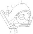
图1为本发明按钮装置的立体外观图。Fig. 1 is a three-dimensional appearance view of the button device of the present invention.
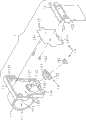
图2为本发明按钮装置的立体分解图。Fig. 2 is a three-dimensional exploded view of the button device of the present invention.
图3为本发明按钮装置的另一立体分解图。Fig. 3 is another perspective exploded view of the button device of the present invention.
图4为本发明按钮装置及手持装置组装前的立体外观图。4 is a three-dimensional appearance view of the button device and the handheld device of the present invention before assembly.
图5为本发明按钮装置及手持装置组装后的立体外观图。5 is a three-dimensional appearance view of the assembled button device and the handheld device of the present invention.
图6为本发明使用时的立体外观图。Fig. 6 is a three-dimensional appearance view of the present invention in use.
附图中主要元件符号说明:Explanation of main component symbols in the attached drawings:
1按钮装置;11基座;110容置空间;111指环部;1111指孔;1112渐扩部;112贯穿槽;1121止挡部;113定位部;1131穿孔;1132定位组件;114卡固部;12底板;1211斜抵面;122透孔;123镂空槽;13按钮;131基部;132按压部;133凸缘;14电路模块;141电路板;1411斜板;1412凹部;142按压开关;121斜凸座;143连接器;2手持装置;21固定部;22接点;23对位槽;24卡固槽。1 button device; 11 base; 110 accommodating space; 111 ring part; 1111 finger hole; 1112 gradually expanding part; 112 through groove; ; 12 bottom plate; 1211 inclined surface; 122 through hole; 123 hollow groove; 13 button; 131 base; 132 pressing part; 133 flange; 14 circuit module; 141 circuit board; 121 oblique convex seat; 143 connector; 2 handheld device; 21 fixed part; 22 contact; 23 alignment slot;
具体实施方式Detailed ways
本发明所采用的技术手段及其构造,兹绘图就本发明的较佳实施例详加说明其特征与功能如下,以利完全了解。The technical means and structures adopted by the present invention are described in detail with respect to the preferred embodiments of the present invention. The features and functions are as follows for complete understanding.
请参阅图1、图2、图3所示,为本发明按钮装置的立体外观图、立体分解图及另一立体分解图,由图中可以清楚看出,其按钮装置1包括基座11、底板12、按钮13及电路模块14,其中:Please refer to Fig. 1, Fig. 2, and Fig. 3, which are the three-dimensional appearance diagram, three-dimensional exploded view and another three-dimensional exploded view of the button device of the present invention. It can be clearly seen from the figure that the
该基座11前方为凹设有容置空间110,基座11后方则凸设有具侧向指孔1111的指环部111,且指环部111二侧壁连接基座11处为具有渐扩部1112,并于指孔1111邻近基座11的侧壁面上方处设有连通至容置空间110的贯穿槽112,贯穿槽112邻近指孔1111的侧壁面具有阶状止挡部1121,且基座11于指环部111左、右处设有二个或二个以上的定位部113,定位部113具有供定位组件1132插入且伸至容置空间110外部的穿孔1131。The front of the
该底板12为罩覆于基座11的容置空间110,且底板12上方凸设有置入贯穿槽112内的斜凸座121,斜凸座121上具有朝向指孔1111的斜抵面1211,再于底板12上穿设有一个或一个以上的透孔122,底板12左右侧边并凹设有二个或二个以上对正基座11各定位部113以供定位组件1132穿过的镂空槽123。The
该按钮13为具有位于基座11贯穿槽112内的基部131,且基部131后侧为延伸有凸伸至指孔1111中的按压部132,基部131前侧周缘则延伸有呈阶状且抵持于贯穿槽112止挡部1121的凸缘133。The
该电路模块14为具有装设于基座11容置空间110内并抵贴于底板12的电路板141,且电路模块14为于电路板141上延伸有抵靠于底板12上斜凸座121斜抵面1211的斜板1411,电路板141左右侧边则凹设有对正各镂空槽123以供各定位组件1132穿过的复数凹部1412,斜板1411邻近贯穿槽112的表面上电性连接有按钮13按压时触发的按压开关142,再于电路板141上电性连接有一个或一个以上朝底板12延伸并穿过各透孔122伸出至外部的连接器143。The
请参阅图1、图2、图3、图4、图5所示,为本发明按钮装置的立体外观图、立体分解图、另一立体分解图、按钮装置及手持装置组装前的立体外观图及组装后的立体外观图,由图中可以清楚看出,该按钮装置1为装设于手持装置2上,手持装置2背面为设有二个或二个以上的固定部21,其固定部21可为螺孔或穿孔,且二个或二个以上固定部21之间为设有复数导电接点22;该按钮装置1为装设于手持装置2背面,按钮装置1利用基座11二个或二个以上穿出底板12各镂空槽123的定位组件1132对正锁固于相对的固定部21内形成定位,且电路模块14伸出至底板12各透孔122外的一个或一个以上连接器143,为与手持装置2背面一个或一个以上的导电接点22相对正形成电性接触,便完成组装动作。Please refer to Fig. 1, Fig. 2, Fig. 3, Fig. 4, and Fig. 5, which are the three-dimensional appearance diagram, the three-dimensional exploded view, another three-dimensional exploded view, the three-dimensional appearance view of the button device and the handheld device before assembly of the button device of the present invention And the three-dimensional appearance diagram after assembly, it can be clearly seen from the figure that the
此外,手持装置2背面为可凹设有对位槽23,则二个或二个以上的固定部21及复数导电接点22位于对位槽23中,其对位槽23形状为相同于按钮装置1的基座11,则按钮装置1组装时便可通过置入对位槽23方式来形成确实对正,让一个或一个以上的连接器143与导电接点22可确实对正形成电性接触。In addition, the back of the
请参阅图2、图3、图4、图5、图6所示,为本发明按钮装置的立体分解图、另一立体分解图、按钮装置及手持装置组装前的立体外观图、组装后的立体外观图及使用时的立体外观图,由图中可以清楚看出,该手持装置2使用时,使用者是用单手握持住手持装置2,让手掌位于手持装置2背面,并让姆指及其它四指分别位于手持装置2左、右侧壁面,且以其中一只手指穿过手持装置2背面按钮装置1的指孔1111,让使用者维持原本的手握姿势,且该手指可利用按压指孔1111内按钮13的按压部132来触发电路模块14的按压开关142,由此产生讯号并通过一个或一个以上的连接器143将讯号经由相对应的各导电接点22传输至手持装置2内,使用者可依照个人使用需求,于手持装置2中设定最常使用的功能为按钮13按压后执行的预定功能,以此达到快捷键的效果。Please refer to Fig. 2, Fig. 3, Fig. 4, Fig. 5, and Fig. 6, which are a three-dimensional exploded view of the button device of the present invention, another three-dimensional exploded view, a three-dimensional appearance view of the button device and the handheld device before assembly, and the assembled The three-dimensional appearance diagram and the three-dimensional appearance diagram during use can be clearly seen from the figure that when the handheld device 2 is used, the user holds the handheld device 2 with one hand, with the palm on the back of the handheld device 2, and the thumb The finger and the other four fingers are respectively located on the left and right side walls of the handheld device 2, and one of the fingers passes through the finger hole 1111 of the button device 1 on the back of the handheld device 2, allowing the user to maintain the original hand-holding posture, and the finger can Press the pressing part 132 of the button 13 in the finger hole 1111 to trigger the pressing switch 142 of the circuit module 14, thereby generating a signal and transmitting the signal to the handheld device through one or more connectors 143 through the corresponding conductive contacts 22 2, the user can set the most frequently used function in the handheld device 2 as a predetermined function to be executed after pressing the button 13 according to personal needs, so as to achieve the effect of a shortcut key.
由于手持装置2的复数按键都位在前表面上,且使用者的姆指或其它四指要从手持装置2左、右侧壁面伸至前表面来按压按键是很不灵活、不方便的,且又仅能按压到周缘的按键,若要按压到中央的按键或是要方便的按压,使用者便需要改变手握的姿势,由按钮装置1的指孔1111及按钮13,便可让使用者在通过快捷键方式控制手持装置2启动最常使用的预定功能,以此减少改变手握的姿势的次数,进而达到方便使用的效果。Since the plurality of buttons of the
且若使用者在握持手持装置2时,因碰撞或手滑等原因让手持装置2脱离时,因其中一只手指穿过手持装置2背面按钮装置1的指孔1111,便可利用该手指支撑住手持装置2,即可避免手持装置2摔落或碰撞,进而可降低损坏机率及减少维修次数;另,由于按钮装置1结构简单、组件少、体积小,使得制造材料随的减少,进而可降低制造成本、减轻重量。And if the user is holding the hand-held
再者,由于手持装置2背面为具有复数固定部21及导电接点22,若使用者因个人使用习惯或手部尺寸大小的原因,而需要更换具不同尺寸指孔1111的按钮装置1,或是拆卸按钮装置1改为装设传统的枪型手把或背带时,便可将按钮装置1上二个或二个以上的定位组件1132松脱离开手持装置2背面二个或二个以上的固定部21,此时便可将按钮装置1拆离来进行更换作业,以此便能让手持装置2符合不同使用者的使用习惯,进而达到提升具按钮装置1的手持装置2的适用性。Furthermore, since the back of the
请参阅图4、图5所示,为本发明按钮装置及手持装置组装前的立体外观图、组装后的立体外观图,由图中可以清楚看出,该按钮装置1的基座11可于上侧壁或下侧壁凸设有一个或一个以上的卡固部114,手持装置2则于对位槽23相对应的上侧壁或下侧壁凹设有卡固槽24,则按钮装置1组装时,便可以基座11倾斜方式将各卡固部114插入对位槽23的各卡固槽24内,再将基座11旋动让基座11进入对位槽23内,不仅可让基座11方便对位置入对位槽23,且可避免基座11旋动时偏摆而无法置入对位槽23的问题,再者,通过二个或二个以上的定位组件1132让按钮装置1固定于手持装置2后,因左、右侧各定位组件1132及上侧壁或下侧壁的各卡固部114,让按钮装置1与手持装置2由三点以上的定位处而不会移动或旋动,进而具有确实定位的效果。Please refer to Fig. 4 and Fig. 5, which are the three-dimensional appearance diagrams before and after assembly of the button device and the handheld device of the present invention. It can be clearly seen from the figures that the
上述的手持装置2为一掌上型计算机,其可具有行动电话(2G或3G)、全球卫星定位系统(GPS)、无线传输(蓝芽或无线网络)或数据撷取(读取一维条形码、二维条形码、图像文件、RFID卷标、磁条卡或IC卡等)的功能,且手持装置2前表面可具有屏幕及复数按键,其手持装置2至少具有计算机及数据撷取的功能,然而有关手持装置2为公知的技术,且该细部构成非本发明的要点,兹不再赘述。The above-mentioned
上述的按钮装置1可于指环部111邻近基座11的上方或下方穿设有贯穿槽112,且基座11左右二侧的二个或二个以上定位部113则可位于邻近或远离贯穿槽112一侧,其仅具供按钮13装设及供各定位组件1132固定于手持装置2的功能即可,非因此即局限本发明的范围,如利用其它修饰及等效结构变化,均应同理包含于本发明申请的权利要求范围内。The above-mentioned
上述本发明的手持装置的按钮指环于实际使用时,为具有下列各项优点,如:The above-mentioned button ring of the handheld device of the present invention has the following advantages in actual use, such as:
一)该按钮装置1装设于手持装置2背面后,使用者可通过一般方式来握持手持装置2,其中一手指便可穿过按钮装置1的指孔1111,便可利用该手指按压指孔1111侧壁面的按钮13,让电路模块14传输讯号至手持装置2,使手持装置2执行使用者最常使用的预定功能,让使用者不需改变手握的姿势来按压手持装置2前表面的按键。1) After the
二)该使用者握持手持装置2时,因其中一只手指穿过手持装置2背面按钮装置1的指孔1111,当碰撞或手滑等原因让手持装置2脱离握持时,便可利用该手指支撑住手持装置2,来避免手持装置2摔落或碰撞。2) When the user holds the hand-held
三)该按钮装置1为将底板12、按钮13及电路模块14组装于基座11上,基座11的体积便是按钮装置1的总体积,且基座11仅略大于手指,所以按钮装置1具有结构简单、组件少的特性,使得制造材料随的减少。3) The
四)该按钮装置1可利用二个或二个以上的定位组件1132松脱离开手持装置2背面二个或二个以上的固定部21,来将按钮装置1快速拆离手持装置2,便可更换成具不同尺寸指孔1111的按钮装置1、背带或枪型手把,藉此让手持装置2符合不同使用者的使用习惯。4) The
故,本发明为主要针对手持装置的按钮指环,而可将按钮装置1的基座11容置空间110罩设底板12,基座11后方指环部111的指孔1111侧壁上的贯穿槽112则装设按钮13,并于基座11容置空间110内装设电路模块14,让使用者握持手持装置2时一手指穿过指孔1111,除可让手持装置2脱离握持时,利用该手指支撑住手持装置2,还可通过该手指按压指孔1111侧壁面的按钮13,让电路模块14传输讯号至手持装置2来执行最常使用的预定功能,让使用者不需改变手握的姿势,以提升使用方便性、降低损坏机率及减少维修次数为主要保护重点,惟,以上所述仅为本发明的较佳实施例而已,非因此即局限本发明的权利范围,故举凡运用本发明说明书及附图内容所为的简易修饰及等效结构变化,均应同理包含于本发明的权利要求范围内。Therefore, the present invention is mainly aimed at the button ring of the handheld device, and the
Claims (10)
Translated fromChinesePriority Applications (1)
| Application Number | Priority Date | Filing Date | Title |
|---|---|---|---|
| CN201110204004.8ACN102891027B (en) | 2011-07-21 | 2011-07-21 | Button ring of handheld device |
Applications Claiming Priority (1)
| Application Number | Priority Date | Filing Date | Title |
|---|---|---|---|
| CN201110204004.8ACN102891027B (en) | 2011-07-21 | 2011-07-21 | Button ring of handheld device |
Publications (2)
| Publication Number | Publication Date |
|---|---|
| CN102891027Atrue CN102891027A (en) | 2013-01-23 |
| CN102891027B CN102891027B (en) | 2014-12-10 |
Family
ID=47534504
Family Applications (1)
| Application Number | Title | Priority Date | Filing Date |
|---|---|---|---|
| CN201110204004.8AExpired - Fee RelatedCN102891027B (en) | 2011-07-21 | 2011-07-21 | Button ring of handheld device |
Country Status (1)
| Country | Link |
|---|---|
| CN (1) | CN102891027B (en) |
Citations (6)
| Publication number | Priority date | Publication date | Assignee | Title |
|---|---|---|---|---|
| US1667067A (en)* | 1927-08-29 | 1928-04-24 | Chesley Frank | Moistening device |
| US4020527A (en)* | 1976-01-02 | 1977-05-03 | Neill Wilbur J O | Grip for a hand held portable device |
| US20020067342A1 (en)* | 2000-12-05 | 2002-06-06 | Proper Kenneth W. | Computer mouse |
| JP2005293512A (en)* | 2004-04-05 | 2005-10-20 | Itsuo Kumazawa | Finger-worn type data input device |
| CN101465225A (en)* | 2007-12-19 | 2009-06-24 | 宏达国际电子股份有限公司 | Input device and handheld electronic device |
| JP2011035810A (en)* | 2009-08-05 | 2011-02-17 | Hirono Tekkosho:Kk | Mobile terminal holder |
- 2011
- 2011-07-21CNCN201110204004.8Apatent/CN102891027B/ennot_activeExpired - Fee Related
Patent Citations (6)
| Publication number | Priority date | Publication date | Assignee | Title |
|---|---|---|---|---|
| US1667067A (en)* | 1927-08-29 | 1928-04-24 | Chesley Frank | Moistening device |
| US4020527A (en)* | 1976-01-02 | 1977-05-03 | Neill Wilbur J O | Grip for a hand held portable device |
| US20020067342A1 (en)* | 2000-12-05 | 2002-06-06 | Proper Kenneth W. | Computer mouse |
| JP2005293512A (en)* | 2004-04-05 | 2005-10-20 | Itsuo Kumazawa | Finger-worn type data input device |
| CN101465225A (en)* | 2007-12-19 | 2009-06-24 | 宏达国际电子股份有限公司 | Input device and handheld electronic device |
| JP2011035810A (en)* | 2009-08-05 | 2011-02-17 | Hirono Tekkosho:Kk | Mobile terminal holder |
Also Published As
| Publication number | Publication date |
|---|---|
| CN102891027B (en) | 2014-12-10 |
Similar Documents
| Publication | Publication Date | Title |
|---|---|---|
| US9489054B1 (en) | Keyboard folio with attachment strip | |
| JP6457011B2 (en) | Connector assembly for electronic devices | |
| US9280178B2 (en) | Portable electronic apparatus and expanding platform thereof | |
| US9423836B2 (en) | Super-slim touch keyboard and super-slim cover device for smart keyboard having the same | |
| US8194055B2 (en) | Stylus retaining mechanism for portable electronic device | |
| US8242389B2 (en) | Portable electronic device and method for operating the same | |
| US8299379B2 (en) | Portable electronic device | |
| CN102841636A (en) | Electronic device and fastening mechanism | |
| CN102891027B (en) | Button ring of handheld device | |
| CN106298327B (en) | Button and its keyboard | |
| US20080290858A1 (en) | Hand-held electronic device and operating module thereof | |
| US20080218477A1 (en) | Computer mouse | |
| TWI479365B (en) | Hand button for the handheld device | |
| US20120050168A1 (en) | Handheld input device | |
| US20140117821A1 (en) | Electronic device having card holder | |
| US20120300414A1 (en) | Multi-function dummy card | |
| CN103294977A (en) | Handheld Electronic Devices | |
| CN201937638U (en) | Mobile phone | |
| CN207397284U (en) | Label scanning device | |
| CN102012752A (en) | Input device, operation method and optical reflector module | |
| CN102065157A (en) | Base of hand-held device | |
| CN101739064A (en) | Portable electronic device | |
| TW201336375A (en) | Handheld electronic device | |
| KR20130070866A (en) | Smart key-board | |
| TW201512903A (en) | Keyboard assembly |
Legal Events
| Date | Code | Title | Description |
|---|---|---|---|
| C06 | Publication | ||
| PB01 | Publication | ||
| C10 | Entry into substantive examination | ||
| SE01 | Entry into force of request for substantive examination | ||
| C14 | Grant of patent or utility model | ||
| GR01 | Patent grant | ||
| CF01 | Termination of patent right due to non-payment of annual fee | ||
| CF01 | Termination of patent right due to non-payment of annual fee | Granted publication date:20141210 Termination date:20190721 |