CN102884375A - Illumination device and illumination system - Google Patents
Illumination device and illumination systemDownload PDFInfo
- Publication number
- CN102884375A CN102884375ACN2011800175354ACN201180017535ACN102884375ACN 102884375 ACN102884375 ACN 102884375ACN 2011800175354 ACN2011800175354 ACN 2011800175354ACN 201180017535 ACN201180017535 ACN 201180017535ACN 102884375 ACN102884375 ACN 102884375A
- Authority
- CN
- China
- Prior art keywords
- lighting device
- light
- light source
- remote control
- bulb
- Prior art date
- Legal status (The legal status is an assumption and is not a legal conclusion. Google has not performed a legal analysis and makes no representation as to the accuracy of the status listed.)
- Granted
Links
Images


Classifications
- F—MECHANICAL ENGINEERING; LIGHTING; HEATING; WEAPONS; BLASTING
- F21—LIGHTING
- F21V—FUNCTIONAL FEATURES OR DETAILS OF LIGHTING DEVICES OR SYSTEMS THEREOF; STRUCTURAL COMBINATIONS OF LIGHTING DEVICES WITH OTHER ARTICLES, NOT OTHERWISE PROVIDED FOR
- F21V3/00—Globes; Bowls; Cover glasses
- F21V3/04—Globes; Bowls; Cover glasses characterised by materials, surface treatments or coatings
- F21V3/06—Globes; Bowls; Cover glasses characterised by materials, surface treatments or coatings characterised by the material
- F21V3/061—Globes; Bowls; Cover glasses characterised by materials, surface treatments or coatings characterised by the material the material being glass
- F—MECHANICAL ENGINEERING; LIGHTING; HEATING; WEAPONS; BLASTING
- F21—LIGHTING
- F21K—NON-ELECTRIC LIGHT SOURCES USING LUMINESCENCE; LIGHT SOURCES USING ELECTROCHEMILUMINESCENCE; LIGHT SOURCES USING CHARGES OF COMBUSTIBLE MATERIAL; LIGHT SOURCES USING SEMICONDUCTOR DEVICES AS LIGHT-GENERATING ELEMENTS; LIGHT SOURCES NOT OTHERWISE PROVIDED FOR
- F21K9/00—Light sources using semiconductor devices as light-generating elements, e.g. using light-emitting diodes [LED] or lasers
- F21K9/20—Light sources comprising attachment means
- F21K9/23—Retrofit light sources for lighting devices with a single fitting for each light source, e.g. for substitution of incandescent lamps with bayonet or threaded fittings
- F—MECHANICAL ENGINEERING; LIGHTING; HEATING; WEAPONS; BLASTING
- F21—LIGHTING
- F21V—FUNCTIONAL FEATURES OR DETAILS OF LIGHTING DEVICES OR SYSTEMS THEREOF; STRUCTURAL COMBINATIONS OF LIGHTING DEVICES WITH OTHER ARTICLES, NOT OTHERWISE PROVIDED FOR
- F21V23/00—Arrangement of electric circuit elements in or on lighting devices
- F21V23/04—Arrangement of electric circuit elements in or on lighting devices the elements being switches
- F21V23/0435—Arrangement of electric circuit elements in or on lighting devices the elements being switches activated by remote control means
- H—ELECTRICITY
- H05—ELECTRIC TECHNIQUES NOT OTHERWISE PROVIDED FOR
- H05B—ELECTRIC HEATING; ELECTRIC LIGHT SOURCES NOT OTHERWISE PROVIDED FOR; CIRCUIT ARRANGEMENTS FOR ELECTRIC LIGHT SOURCES, IN GENERAL
- H05B47/00—Circuit arrangements for operating light sources in general, i.e. where the type of light source is not relevant
- H05B47/10—Controlling the light source
- H05B47/105—Controlling the light source in response to determined parameters
- H05B47/14—Controlling the light source in response to determined parameters by determining electrical parameters of the light source
- F—MECHANICAL ENGINEERING; LIGHTING; HEATING; WEAPONS; BLASTING
- F21—LIGHTING
- F21K—NON-ELECTRIC LIGHT SOURCES USING LUMINESCENCE; LIGHT SOURCES USING ELECTROCHEMILUMINESCENCE; LIGHT SOURCES USING CHARGES OF COMBUSTIBLE MATERIAL; LIGHT SOURCES USING SEMICONDUCTOR DEVICES AS LIGHT-GENERATING ELEMENTS; LIGHT SOURCES NOT OTHERWISE PROVIDED FOR
- F21K9/00—Light sources using semiconductor devices as light-generating elements, e.g. using light-emitting diodes [LED] or lasers
- F21K9/60—Optical arrangements integrated in the light source, e.g. for improving the colour rendering index or the light extraction
- F21K9/64—Optical arrangements integrated in the light source, e.g. for improving the colour rendering index or the light extraction using wavelength conversion means distinct or spaced from the light-generating element, e.g. a remote phosphor layer
- F—MECHANICAL ENGINEERING; LIGHTING; HEATING; WEAPONS; BLASTING
- F21—LIGHTING
- F21V—FUNCTIONAL FEATURES OR DETAILS OF LIGHTING DEVICES OR SYSTEMS THEREOF; STRUCTURAL COMBINATIONS OF LIGHTING DEVICES WITH OTHER ARTICLES, NOT OTHERWISE PROVIDED FOR
- F21V17/00—Fastening of component parts of lighting devices, e.g. shades, globes, refractors, reflectors, filters, screens, grids or protective cages
- F21V17/10—Fastening of component parts of lighting devices, e.g. shades, globes, refractors, reflectors, filters, screens, grids or protective cages characterised by specific fastening means or way of fastening
- F21V17/12—Fastening of component parts of lighting devices, e.g. shades, globes, refractors, reflectors, filters, screens, grids or protective cages characterised by specific fastening means or way of fastening by screwing
- F—MECHANICAL ENGINEERING; LIGHTING; HEATING; WEAPONS; BLASTING
- F21—LIGHTING
- F21V—FUNCTIONAL FEATURES OR DETAILS OF LIGHTING DEVICES OR SYSTEMS THEREOF; STRUCTURAL COMBINATIONS OF LIGHTING DEVICES WITH OTHER ARTICLES, NOT OTHERWISE PROVIDED FOR
- F21V29/00—Protecting lighting devices from thermal damage; Cooling or heating arrangements specially adapted for lighting devices or systems
- F21V29/85—Protecting lighting devices from thermal damage; Cooling or heating arrangements specially adapted for lighting devices or systems characterised by the material
- F21V29/87—Organic material, e.g. filled polymer composites; Thermo-conductive additives or coatings therefor
- F—MECHANICAL ENGINEERING; LIGHTING; HEATING; WEAPONS; BLASTING
- F21—LIGHTING
- F21V—FUNCTIONAL FEATURES OR DETAILS OF LIGHTING DEVICES OR SYSTEMS THEREOF; STRUCTURAL COMBINATIONS OF LIGHTING DEVICES WITH OTHER ARTICLES, NOT OTHERWISE PROVIDED FOR
- F21V3/00—Globes; Bowls; Cover glasses
- F21V3/04—Globes; Bowls; Cover glasses characterised by materials, surface treatments or coatings
- F21V3/06—Globes; Bowls; Cover glasses characterised by materials, surface treatments or coatings characterised by the material
- F21V3/062—Globes; Bowls; Cover glasses characterised by materials, surface treatments or coatings characterised by the material the material being plastics
- F—MECHANICAL ENGINEERING; LIGHTING; HEATING; WEAPONS; BLASTING
- F21—LIGHTING
- F21V—FUNCTIONAL FEATURES OR DETAILS OF LIGHTING DEVICES OR SYSTEMS THEREOF; STRUCTURAL COMBINATIONS OF LIGHTING DEVICES WITH OTHER ARTICLES, NOT OTHERWISE PROVIDED FOR
- F21V31/00—Gas-tight or water-tight arrangements
- F21V31/04—Provision of filling media
- F—MECHANICAL ENGINEERING; LIGHTING; HEATING; WEAPONS; BLASTING
- F21—LIGHTING
- F21Y—INDEXING SCHEME ASSOCIATED WITH SUBCLASSES F21K, F21L, F21S and F21V, RELATING TO THE FORM OR THE KIND OF THE LIGHT SOURCES OR OF THE COLOUR OF THE LIGHT EMITTED
- F21Y2113/00—Combination of light sources
- F21Y2113/10—Combination of light sources of different colours
- F21Y2113/13—Combination of light sources of different colours comprising an assembly of point-like light sources
- F—MECHANICAL ENGINEERING; LIGHTING; HEATING; WEAPONS; BLASTING
- F21—LIGHTING
- F21Y—INDEXING SCHEME ASSOCIATED WITH SUBCLASSES F21K, F21L, F21S and F21V, RELATING TO THE FORM OR THE KIND OF THE LIGHT SOURCES OR OF THE COLOUR OF THE LIGHT EMITTED
- F21Y2115/00—Light-generating elements of semiconductor light sources
- F21Y2115/10—Light-emitting diodes [LED]
Landscapes
- Engineering & Computer Science (AREA)
- General Engineering & Computer Science (AREA)
- Physics & Mathematics (AREA)
- Microelectronics & Electronic Packaging (AREA)
- Optics & Photonics (AREA)
- Circuit Arrangement For Electric Light Sources In General (AREA)
- Arrangement Of Elements, Cooling, Sealing, Or The Like Of Lighting Devices (AREA)
- Non-Portable Lighting Devices Or Systems Thereof (AREA)
Abstract
Translated fromChinese
Description
Translated fromChinese技术领域technical field
本发明涉及具有发光二极管等光源的照明装置,尤其涉及呈灯泡状的照明装置。The present invention relates to an illuminating device with a light source such as a light emitting diode, in particular to an illuminating device in the shape of a light bulb.
背景技术Background technique
日本专利申请公开公报“特开平11-312591号公报”(专利文献1)中揭示了一种照明装置,该照明装置具备了荧光灯等光源、驱动光源的换流器等点亮装置、通过控制点亮装置来控制光源状态的微机、接收遥控信号并向微机提供信号的接收部、检测来自接收部的信号的信号检测部。Japanese Patent Application Publication "JP-A-11-312591" (Patent Document 1) discloses a lighting device that includes a light source such as a fluorescent lamp, a lighting device such as an inverter for driving the light source, and a control point. The microcomputer that controls the state of the light source by turning on the device, the receiving unit that receives the remote control signal and provides the signal to the microcomputer, and the signal detection unit that detects the signal from the receiving unit.
当要熄灭光源时,断开与微机相连的开关单元来切断向微机提供的直流电,并进入待机状态,待机状态时,直流电间歇性地被提供给接收部和信号检测部。而当接收部收到了遥控信号并输出了信号时,根据信号检测部输出的信号,直流电被提供给微机。因此,在光源熄灭时,因开关单元的切断,直流电不会提供给微机,所以能降低待机功率。然而,专利文献1的照明装置所涉及的是荧光灯等光源,因此用以大幅降低待机功率的装置(例如开关单元等)并非内置于荧光管内,而是作为与荧光管另行设置的部件而配置在照明装置内。When the light source is to be extinguished, the switch unit connected to the microcomputer is disconnected to cut off the direct current supplied to the microcomputer, and enters a standby state. In the standby state, the direct current is intermittently supplied to the receiving part and the signal detection part. And when the receiving part receives the remote control signal and outputs the signal, direct current is supplied to the microcomputer according to the signal output by the signal detecting part. Therefore, when the light source is turned off, direct current is not supplied to the microcomputer due to the cut-off of the switching unit, so that the standby power can be reduced. However, since the lighting device of
此外,目前有一种以LED灯泡为光源的照明装置得到了实用化,该LED灯泡内具备遥控接收器,以受理遥控器发出的点亮/熄灭的指示操作。In addition, a lighting device using an LED light bulb as a light source has been put into practical use at present. The LED light bulb is equipped with a remote control receiver to receive the on/off instruction operation from the remote control.
〔现有技术文献〕[Prior Art Literature]
专利文献1:日本国专利申请公开公报“特开平11-312591号公报”;1999年11月9日公开。Patent Document 1: Japanese Patent Application Publication "JP-A-11-312591"; published on November 9, 1999.
发明内容Contents of the invention
〔发明所要解决的课题〕[Problem to be solved by the invention]
就专利文献1的照明装置而言,由于光源即荧光管中无法内置用以大幅降低待机功率的装置,且该装置是与荧光管另行设置的部件,因此当想要减低待机功率时,无法仅通过例如交换荧光管来降低待机功率,而是需要交换整个照明装置。With regard to the lighting device of
另一方面,对于将LED灯泡等用作光源且该LED灯泡具备用以受理遥控器发出的点亮/熄灭指示操作的遥控接收器的照明装置而言,尽管其照明时所需的消耗功率本身较低,且待机功率稍低于照明时所需的消耗功率的1/10,然而人们一直盼望能降低其待机功率。若要通过灯泡内的控制部来停下供电或进一步降低待机功率,就需要追加电路,也就是需要在照明装置中安设与灯泡另行设置的作为另设部件的追加电路。On the other hand, for a lighting device that uses an LED light bulb as a light source and the LED light bulb has a remote control receiver for accepting the on/off instruction operation from the remote controller, although the power consumption itself required for lighting Low, and the standby power is slightly lower than 1/10 of the power consumption required for lighting, but people have been looking forward to reducing its standby power. To stop the power supply or further reduce the standby power through the control unit in the light bulb, an additional circuit is required, that is, an additional circuit as an additional component that is provided separately from the light bulb needs to be installed in the lighting device.
本发明的目的在于提供一种具有如下特性的照明装置及照明系统:在操作遥控操作装置即遥控器来熄灭照明后,通知使用者目前电源为待机状态,然后由使用者利用墙壁上的开关来切断主电源,这样便无需增大以往的灯泡的大小,而仅通过交换灯泡就能够降低待机功率。The purpose of the present invention is to provide a lighting device and a lighting system with the following characteristics: After operating the remote control device, that is, the remote controller to turn off the lighting, the user is notified that the current power supply is in a standby state, and then the user uses the switch on the wall to turn off the lighting. By cutting off the main power supply, the standby power can be reduced by simply exchanging the bulb without increasing the size of the conventional bulb.
〔用以解决课题的技术方案〕[Technical solution to solve the problem]
本发明的照明装置的特征在于具备:接收部,从遥控操作装置接收用以指示光源的熄灭的熄灭指示信号;控制部,根据所述接收部所接收的熄灭指示信号来熄灭所述光源,并在经过了规定的时间之后,通知使用者目前电源为待机状态。The lighting device of the present invention is characterized by comprising: a receiving unit for receiving a extinguishing instruction signal for instructing extinguishing of the light source from the remote control device; a control unit for extinguishing the light source according to the extinguishing instruction signal received by the receiving unit, and After a predetermined time elapses, the user is notified that the power supply is currently in a standby state.
通过上述方案,能够在自遥控操作装置发出熄灭指示信号来熄灭光源,且经过了规定的时间之后,通知使用者目前电源为待机状态。因此,对于根据该通知而得知了待机功率正在浪费的使用者而言,能给予该使用者一个切断主电源的契机乃至动机。其结果是能够防止浪费消耗待机功率。Through the above solution, it is possible to notify the user that the power supply is currently in a standby state after a extinguishing instruction signal is sent from the remote control operation device to extinguish the light source, and after a predetermined time has elapsed. Therefore, for the user who has learned that the standby power is being wasted based on the notification, the user can be given an opportunity or motivation to turn off the main power supply. As a result, wasteful consumption of standby power can be prevented.
本发明的照明系统具备照明装置以及遥控操作装置,其特征在于:所述照明装置具有:接收部,从所述遥控操作装置接收熄灭指示信号;控制部,根据所述接收部所接收的熄灭指示信号来熄灭光源,并在经过了规定的时间之后,通知使用者目前电源为待机状态,所述遥控操作装置具有:切换单元,被用于维持电源待机持续状态;发送部,与所述切换单元的切换动作相对应地,向所述接收部发送用以维持所述电源待机持续状态的维持信号。The lighting system of the present invention includes a lighting device and a remote control device, wherein the lighting device has: a receiving unit for receiving a extinguishing instruction signal from the remote operating device; signal to turn off the light source, and after a specified time, notify the user that the current power supply is in a standby state. The remote control device has: a switching unit, which is used to maintain the continuous power supply standby state; a sending unit, which communicates with the switching unit Corresponding to the switching operation, a maintenance signal for maintaining the power standby state is sent to the receiving unit.
通过上述方案,在自遥控操作装置发出熄灭指示信号来熄灭光源且经过了规定的时间之后,得知电源正为待机状态的使用者能够通过切换遥控操作装置中的切换单元来维持电源待机持续状态。因此,能停止不必要的规定模式下的点亮或闪烁,因此不会出现例如在寝室中就寝时因光源进行规定模式的点亮而妨碍使用者睡眠的情况。Through the above arrangement, after the light source is turned off by sending an extinguishing instruction signal from the remote operation device and a predetermined time has elapsed, the user who knows that the power supply is in the standby state can maintain the continuous power supply standby state by switching the switching unit in the remote control operation device. . Therefore, unnecessary lighting or flickering in a predetermined pattern can be stopped, so that, for example, the light source is turned on in a predetermined pattern while sleeping in a dormitory, preventing the user's sleep from being disturbed.
(发明的效果)(effect of invention)
通过本发明的上述方案,无需改变照明装置的外观大小,且能够让使用者得知待机功率正被使用,从而防止浪费消耗待机功率。Through the above solution of the present invention, there is no need to change the size of the appearance of the lighting device, and the user can be informed that the standby power is being used, thereby preventing wasteful consumption of the standby power.
附图说明Description of drawings
图1是本发明实施方式的照明装置的外观图。Fig. 1 is an external view of a lighting device according to an embodiment of the present invention.
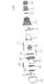
图2是上述照明装置的要部的分解斜视图。Fig. 2 is an exploded perspective view of main parts of the lighting device.
图3是上述照明装置的截面图。Fig. 3 is a cross-sectional view of the lighting device described above.
图4是上述照明装置中设置的光源模块的发光面构造例的俯视图。Fig. 4 is a plan view of an example of a light emitting surface structure of a light source module provided in the lighting device.
图5是上述照明装置中设置的控制部的结构框图。Fig. 5 is a block diagram showing a configuration of a control unit provided in the lighting device.
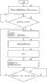
图6是上述照明装置的动作流程图。Fig. 6 is an operation flowchart of the above-mentioned lighting device.
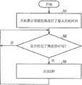
图7是上述照明装置的其他动作的流程图。Fig. 7 is a flowchart of another operation of the lighting device.
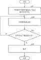
图8是上述照明装置的另一动作的流程图。Fig. 8 is a flowchart of another operation of the lighting device.
图9是上述照明装置的另一动作的流程图。Fig. 9 is a flowchart of another operation of the lighting device.
图10是上述照明装置的另一动作的流程图。Fig. 10 is a flowchart of another operation of the lighting device.
图11是上述照明装置的另一动作的流程图。Fig. 11 is a flowchart of another operation of the lighting device.
〔附图标记说明〕[Description of Reference Signs]
30 控制部30 Control Department
35 控制用微型计算机(控制用微机)35 Microcomputer for control (microcomputer for control)
40 光源模块40 light source module
41 基板41 Substrate
42、43 LED模块(光源)42, 43 LED module (light source)
45 遥控接收部45 Remote control receiver
50 透光部50 Translucent part
100 照明装置100 lighting fixtures
具体实施方式Detailed ways
以下根据本发明各实施方式的附图来说明本发明。图1是照明装置100的外观图。Hereinafter, the present invention will be described based on the drawings of various embodiments of the present invention. FIG. 1 is an external view of a
如图1所示,照明装置100是灯泡型的LED灯泡,其主要具备:作为电源连接部的金属卡口10,其用以嵌入外部灯泡座而与商用电源电连接;散热部13;连结体11,使金属卡口10与散热部13相连结;透光部50,为近乎半球状的壳体,呈中空;圆板状的散热板20,供载置后述的LED模块,且与散热部13构成热传递性连接。As shown in Figure 1, the
图2是照明装置100的要部的分解斜视图。图3是照明装置100的截面图。如图2及图3所示,光源模块40的基板41表面上安装有LED模块42、43,该光源模块40借助螺丝21而安设在散热板20上。LED模块42能放出例如白色的光,LED模块43能放出灯泡设计色的光。发光色并不限定于此,也可以是例如红色、绿色、蓝色等其他颜色。基板41的表面中央处具备有遥控接收部45,遥控接收部45用以接收来自遥控器等遥控操作装置的信号。在光源模块40与散热板20之间,涂敷有用以提高热传导率的热传导膜、高热传导性树脂等,由此能够经由散热板20以及散热部13来将光源模块40产生的热释放到外部。FIG. 2 is an exploded perspective view of main parts of the
散热部13由例如铝等轻量且热传导性高的金属构成,其大致呈圆筒状。另外,散热部13在其圆筒形外周面上具有多个散热槽,从光源模块40传递到散热部13的热量经由散热槽而从外周面释放到外部空气中。另外,在散热部13与散热板20之间设有合成橡胶制的防水密封圈19,以防止水侵入到内部。The
散热部13的内部呈中空,配设有控制部30和用以容纳控制部30的容纳部15等。控制部30经由布线22,向光源模块40的LED模块42、43提供所需的功率(电压、电流)。另外,在控制部30与金属卡口10之间,设有用以将商用电源提供给控制部30的电源线17。The inside of the
在散热部13与连结体11之间设有合成橡胶制的防水环12,以防止水侵入到内部。散热部13与连结体11通过螺丝14而相互固定。A
另外,如图3所示,在容纳部15所容纳的控制部30的周围,充填有高热传导率的合成树脂25(例如聚尿烷树脂等),以有效地使控制部30发出的热量传导至散热部13以及金属卡口10。另外,合成树脂25优选具有高电绝缘性、低透水性、阻燃性。In addition, as shown in FIG. 3 , around the
散热部13内部的电布线处理得以完成后,在散热部13与金属卡口10的机械结合状态下,合成树脂25被充填进散热部13的内部。在此,合成树脂25在充填时为液态。充填完合成树脂25后,在所需的温度下使之硬化。硬化后的合成树脂25不仅与金属卡口10的内面相粘合,且与散热部13的内面相粘合。这样,能够更切实地防止水分从金属卡口10的结合部位侵入。After the electrical wiring process inside the
另外,由于合成树脂25具有较高的电绝缘性,因此能够防止因在散热部13与控制部30的充电部之间发生绝缘破坏而导致短路。此外,由于合成树脂25具有高热传导率,因此控制部30发出的热不仅从散热部13释放,还从介由合成树脂25而构成热传递性连接的金属卡口10进行释放。因此能抑制控制部30的温度上升,提高控制部30中所用的电气部件的可靠性。In addition, since the
在光源模块40的发光面侧,通过螺丝21而安设有反射板23。在反射板23的与LED模块42、43的配置位置相对应的部位,设有与LED模块42、43的尺寸大致相同的插孔。反射板23是以LED模块42、43插入该插孔的这一状态来安设的。反射板23也可以省去不用。On the light emitting surface side of the
透光部50为乳白色的玻璃制品,其通过粘接剂而固定在散热板20上。透光部50并不限于是玻璃制品,也可以采用乳白色的聚碳酸酯树脂等。透光部50若是聚碳酸酯树脂,则能通过旋入螺丝来将透光部50螺紧到散热板20上。The
透光部50中添加有用以使来自LED模块42、43(光源模块40)的光散射的光散射材料50a。光散射材料50a例如具有晶体构造,其光学性质例如可以为高折射率、低光吸收力、高光散射力。例如可以添加荧光体等具有晶体构造的颜料。另外,光散射材料50a的添加比率例如可以是数个百分比。可以采用例如3Ca3(PO4)2Ca(F、Cl)2SbMn来作为荧光体。A light-scattering
由此,当把具有面发光性质的LED模块42、43用作光源时,即使LED模块42、43的光定向范围较狭窄,从LED模块42、43发出的光也能在穿过透光部50时经光散射材料50a而散射,因此通过简单的结构便能扩展配光特性。另外,采用荧光体来作为光散射材料50a时,该荧光体也可以是既能使光发生散射,又受该光的激励而发光的材料。因此,能利用光散射材料50a自身也发光的这一现象来扩展配光范围。Therefore, when the
另外,由于透光部50是中空的近乎半球状壳体,因此能够提供一种使用有LED模块42、43(发光二极管)且具有广配光特性的灯泡型照明装置。In addition, since the light-transmitting
尤其是,由于透光部50与散热板20在比近乎半球状壳体的透光部50的最大外径略小一圈的部位进行结合,因此LED模块42、43发出的光能穿过透光部50表面中的自透光部50与散热板20间的结合部位起,至透光部50的最大外径部位为止的部分,从而该光能沿着从散热部13朝向金属卡口10的方向来照射,由此能进一步扩展配光特性。In particular, since the light-transmitting
虽然在上述图3的例中,透光部50中添加有光散射材料50a,但并不限于该方案。也可以在透光部50上涂敷光散射材料。In the example of FIG. 3 described above, although the light-scattering
上述照明装置100具备了拥有特定发光色的LED灯泡的构造,且照明装置100具有调光功能。The above-mentioned
照明装置100不仅具备调光功能,还具备调色(将发光色调整成期望的颜色)功能。调光、调色是通过遥控用的遥控器来进行的。The
图4是光源模块40的发光面构造例的俯视图。FIG. 4 is a plan view of an example of the light emitting surface structure of the
在光源模块40中,由铝合金等构成的近乎圆形的基板41上配设有发光色互异的多个LED模块42、43,LED模块42、43以相互隔开均一间隔的方式,交互地配置成环形。虽然在图4的例中,LED模块42、43各为3个,但LED模块42、43的数量及配置方式并不限于图4的例子,也能视照明装置的规格及用途来作适宜的变更,例如改变数量或配置成近乎矩形等。基板41也可以是陶瓷基板等。In the
在近乎圆形的基板41的中央,配设有遥控接收部45。图3所示的灯泡型的照明装置100在被安装于照明器具上时,其能被目视到的部分几乎仅为透光部50。因此,例如为了让使用者能通过遥控器来进行遥控操作,遥控接收部45需要设置在能目视到的区域内,即透光部50内。另外,通过将LED模块42、43设置在遥控接收部45的周围来围住遥控接收部45,便能实现照明装置100的小型化。In the center of the substantially
图5是照明装置100的控制部30的结构框图。控制部30主要具备:噪音滤波电路31,用以去除从商用电源等侵入的噪音;整流电路32,对交流电压进行整流,以转换成直流电压;DC/DC转换器33,将整流电路32输出的直流电压转换成所需的直流电压;PWM控制电路34,对DC/DC转换器33输出的直流电压进行脉宽调制,从而控制提供给LED模块42及43的电流;控制用微型计算机(以下简称为控制用微机)35,对控制部30进行控制;电流电压检测电路36,检测流过LED模块42的电流以及施加在LED模块42上的电压;电流电压检测电路37,检测流过LED模块43的电流以及施加在LED模块43上的电压。FIG. 5 is a block diagram showing the configuration of the
遥控接收部45接收用户所操作的遥控器中内置的红外线LED所发出的红外线,并从中提取自遥控器送出的信号,然后将提取的信号输出给控制用微机35。自遥控器送出的信号用来对光源进行例如点亮、熄灭、调光(例如调成70%亮度、50%亮度、30%亮度等)、调色(例如阶段式地将发光色从白色调整成灯泡设计色)。The remote
在说明照明装置的动作之前,先说明一下待机功率。Before explaining the operation of the lighting device, the standby power will be explained.
举一例来说,LED灯泡的消耗功率为7.5W,经遥控器操作而熄灭时的待机功率约为0.6W,其所消耗的待机功率约为点亮时的功率的8%。另外,在通过墙壁上的开关来熄灭了LED灯泡时,由于LED灯泡的供电被切断,因此不消耗待机功率。在白天时间或因外出、外宿等而要长时间关灯时,若是通过遥控器操作来熄灭灯泡,那么便很浪费待机功率,因此最好是采取对策来减少该待机功率。For example, the power consumption of the LED light bulb is 7.5W, and the standby power when it is turned off by the remote control is about 0.6W, and the standby power consumed by it is about 8% of the power when it is turned on. In addition, when the LED light bulb is turned off by the switch on the wall, since the power supply of the LED light bulb is cut off, standby power is not consumed. During the daytime or when the lamp needs to be turned off for a long time due to going out or sleeping out, if the bulb is turned off by the remote control, the standby power is wasted, so it is best to take countermeasures to reduce the standby power.
然而,若在LED灯泡内部装入用以大幅降低接收部和微机的待机功率的控制装置,则LED灯泡的形状会过度增大,存在装不进灯泡罩以及不美观等这些缺少实用性的问题。比如说,当通过遥控器操作来切断液晶电视等的电源时,作为电源灯的LED等在电源待机状态下会点亮成红色等颜色,对此,可以采用与此相同的方法,将LED灯泡内的1个LED点亮。然而采用该方案时,LED的光会经上述光散射材料50a被全体散射,导致1个LED整体的亮度相对减弱,因此使用者难以发觉。为了让使用者在白天的亮度下也能发觉LED的点亮,例如可以使LED点亮至40W白炽灯泡以上的亮度,然而光是点亮1个LED,使用者是难以发觉的。对此,根据图5及图6来说明一个在考虑到以上事项的基础上且在不新追加部件等的前提下向使用者通知待机功率正被使用的技术方案。However, if a control device for greatly reducing the standby power of the receiving unit and the microcomputer is incorporated in the LED bulb, the shape of the LED bulb will be too large, and there are problems such as lack of practicality such as not being able to fit into the bulb cover, and being unsightly. . For example, when the power supply of LCD TV is cut off by remote control operation, the LED as the power lamp will light up in red and other colors in the power standby state. For this, the same method as this can be used to turn off the
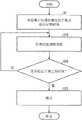
图6是照明装置的动作流程图。在步骤S1中,控制用微机35确认到遥控接收部45(参照图3、图4、图5)收到了表达“是用遥控器控制的熄灭”的熄灭指示信号,然后在LED模块42、43熄灭的同时,控制用微机35开始进行“熄灭后的时间累计”。在步骤S2中,控制用微机35例如确认“是否经过了5小时?”,若累计时间未达5小时(在步骤S2为“否”),则反复进行步骤S2,直至达到了5小时为止。若达到了5小时(在步骤S2为“是”),则在步骤S3中将LED模块42、43点亮5秒,以此作为一个警报来使使用者发觉“目前是用遥控器执行了熄灭的熄灭状态,且正在消耗待机功率”,同时控制用微机35对警报账户进行累加(变量A=变量A+1)(步骤S3)。在此,变量A是从初始值0开始累加的。Fig. 6 is an operation flowchart of the lighting device. In step S1, the
在接下来的步骤S4中,控制用微机35对LED模块42、43进行“亮度的阶段式变更”(步骤S4)。In the next step S4, the
在接下来的步骤S5中,控制用微机35使LED模块42、43“熄灭”。In the next step S5, the
通过这一连的处理流程,能够向使用者通知:目前是经遥控器控制而熄灭的熄灭状态,是电源待机状态,且正在消耗待机功率。通过该通知而得知待机功率正被消耗的使用者能通过切断墙壁上的开关等来切断主电源,由此熄灯。这样便能停止消耗待机功率,从而防止浪费性地消耗待机功率。Through this continuous processing flow, it is possible to notify the user that it is currently in an extinguished state controlled by the remote control, is in a power standby state, and is consuming standby power. The user who knows that the standby power is being consumed by this notification can turn off the main power supply by turning off a switch on the wall or the like, thereby turning off the light. This stops consumption of standby power, thereby preventing wasteful consumption of standby power.
另外,可以在遥控器的操作部中设置供维持电源待机持续状态的切换开关,通过操作该切换开关,遥控器的发送部便发出用以维持(持续地消耗待机功率)电源待机持续状态的维持信号,然后由遥控接收部45接收该维持信号。控制用微机35根据从遥控接收部45输出的信号,如图6所示流程那样,即使经过了5小时也不点亮LED模块42、43,而是维持电源待机持续状态,允许持续地消耗待机功率。In addition, a switch for maintaining the continuous state of power supply standby can be provided in the operation part of the remote controller. By operating the switch, the transmission part of the remote controller sends a message for maintaining (continuously consuming standby power) the continuous state of power supply standby. signal, and then the
在此,照明装置100与遥控操作装置(遥控器)组成为一个照明系统,该照明装置100具备了用以接收来自遥控操作装置的信号且向控制部30输入信号的遥控接收部45、光源(LED模块42、43)、以及控制部30。Here, the
在通过遥控器来选择“持续电源待机状态”时,例如可以通过切换遥控器的操作部中设置的用来一直维持电源待机状态的开关,或通过长按遥控器电源的“接通”开关等来执行选择。When selecting the "continuous power standby state" through the remote control, for example, you can switch the switch provided on the operation part of the remote control to maintain the power standby state, or press and hold the "on" switch of the remote control power supply, etc. to perform the selection.
若通过墙壁上的开关等主电源开关来熄灯,便不会有电流通向照明装置100,因此当通过墙壁上的开关来再次点亮时,控制用微机35便以复位后的初始状态进行工作。而后,在用遥控器来熄灯时,若未被选择成“持续电源待机状态”,便再次从图6的步骤S1起开始处理。If the main power switch such as the switch on the wall is used to turn off the light, no current will flow to the
在流程图的步骤S6中,当变量A成为6时,控制用微机35将警报账户的变量A复位到0。之后,转入步骤S7,以判断“是否经过了(60-10×A)分钟?”。步骤S7被反复进行,直至经过了(60-10×A)分钟为止。若经过了(60-10×A)分钟,则返回步骤S3,以再次从步骤S3起重复处理。In step S6 of the flowchart, when the variable A becomes 6, the
因此,自步骤S5的熄灭动作起至步骤S3的点亮动作为止的经过时间逐次缩短为50分钟、40分钟、30分钟、20分钟、10分钟,然后再次增大到60分钟,其后又缩短为50分钟,如此重复该循环。举具体例而言,在步骤S7中,若A=1,则是在50分钟后返回步骤S3,若A=5,则是在10分钟后返回步骤S3。若在步骤S6中A=6,则复位成A=0,因此从步骤S7起,是在60分钟之后返回到步骤S3。以后,与上述同样地,至点亮动作为止的经过时间逐次缩短为50分钟、40分钟、30分钟、20分钟、10分钟,并反复进行该循环。Therefore, the elapsed time from the extinguishing operation of step S5 to the lighting operation of step S3 is successively shortened to 50 minutes, 40 minutes, 30 minutes, 20 minutes, and 10 minutes, then increased to 60 minutes again, and then shortened again. for 50 minutes, and the cycle was repeated. To give a specific example, in step S7, if A=1, then return to step S3 after 50 minutes, and if A=5, then return to step S3 after 10 minutes. If A=6 in step S6, it is reset to A=0, so it returns to step S3 after 60 minutes from step S7. Thereafter, in the same manner as above, the elapsed time until the lighting operation is gradually shortened to 50 minutes, 40 minutes, 30 minutes, 20 minutes, and 10 minutes, and this cycle is repeated.
虽然在上述步骤S3中进行的是点亮动作,但也可以进行闪烁动作,或进行单次至多次的点亮动作与闪烁动作的组合等。Although the lighting operation is performed in the above-mentioned step S3, a blinking operation may be performed, or a combination of single to multiple lighting operations and blinking operations may be performed.
另外,虽然在步骤S2中判断“是否经过了5小时”,但5小时仅是一个例子,其并不限定于此。例如也可以是15分钟的短时间,或是10小时等。In addition, although "whether 5 hours have passed" is judged in step S2, 5 hours is just an example, and it is not limited to this. For example, it may be a short time of 15 minutes or 10 hours.
虽然在步骤S3中定为“点亮5秒”,但5秒仅是一个例子,其并不限定于此。例如也可以是10秒、60秒等。Although it is set as "lighting for 5 seconds" in step S3, 5 seconds is just an example, and it is not limited to this. For example, 10 seconds, 60 seconds, etc. may be used.
另外,在步骤S6中,虽然定为当A=6时复位成A=0,但并不限定于当A=6时,也可在A=5时复位成A=0,此时的变量A的阈值只要是1以上5以下的整数即可。另外,虽然在步骤S7中判断是否经过了(60-10×A)分钟,但减号左边的值可以超过60,也可低于60。虽然在上述步骤S4中进行“亮度的阶段式变更”,但也可不进行阶段式变更,而是瞬间地改变亮度,还可以按照阶段式变更与瞬间变更的组合来改变亮度。In addition, in step S6, although it is determined to reset to A=0 when A=6, it is not limited to when A=6, it can also be reset to A=0 when A=5, and the variable A at this time The threshold value of is only required to be an integer ranging from 1 to 5. In addition, although it is judged in step S7 whether (60-10*A) minutes have elapsed, the value to the left of the minus sign may exceed 60 or may be less than 60. Although the "gradual change in brightness" is performed in the above-mentioned step S4, the brightness may be changed instantaneously instead of stepwise, or may be changed in combination of stepwise change and instantaneous change.
在寝室等中,若灯光过亮,使用者便会从睡眠中醒来,而通过在遥控器的功能中增加“调光”、“调色”、“持续电源待机状态”这些功能,便能提高便利性。关于闪烁的方法,可以在步骤S4中阶段式地改变亮度并使灯光闪烁,但也可以不改变亮度,而是改变闪烁的次数,或改变每两次闪烁间的时间长度,或进行调色等,也可以采用这些方案的组合。In a dormitory, etc., if the light is too bright, the user will wake up from sleep, and by adding functions such as "dimming", "color adjustment", and "continuous power standby state" to the functions of the remote control, the Improve convenience. Regarding the method of flickering, the brightness can be changed step by step in step S4 and the lights can be flickered, but the brightness can also be changed instead of the number of flickers, or the length of time between each two flickers, or color adjustment, etc. , a combination of these schemes can also be used.
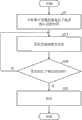
另外,通过使遥控器具备在每当经过了15分钟、30分钟、1小时、2小时等这些固定时间段时来实施点亮的功能,使用者便能得知时间的经过状况,因此便可代替定时器或时钟的功能。另一方面,也可利用控制用微机35的时间累计功能,例如像时钟报时功能那样,反复地在每当经过了1小时时点亮照明装置5秒。图7是照明装置100的其他动作的流程图。在步骤S1中,控制用微机35确认到遥控接收部45(参照图3、图4、图5)收到了表达“是用遥控器控制的熄灭”的熄灭指示信号,然后在LED模块42、43熄灭的同时,控制用微机35开始进行“熄灭后的时间累计”。在步骤S8中,控制用微机35确认“是否经过了规定的时间?”,若累计时间尚未达到规定的时间(在步骤S8为“否”),则反复执行步骤S8,直至达到了规定的时间为止。若达到了规定的时间(在步骤S8为“是”),则使LED模块42、43进行规定的时间长度的点亮,例如点亮5秒(步骤S9)。然后返回步骤S8。上述步骤S8中的“是否经过了规定的时间”中的“规定的时间”例如可以是上述的15分钟、30分钟、1小时、2小时等。In addition, by providing the remote controller with the function of lighting up every time such fixed time periods as 15 minutes, 30 minutes, 1 hour, and 2 hours have passed, the user can know the passage of time, so it is possible to Replaces the function of a timer or clock. On the other hand, the time accumulating function of the
在此,可以在遥控器的操作部中设置“反复进行点亮”开关,或可以通过长按电源的“接通”开关等来转入图7所示的流程。但并不限于上述的例子,只要在每经过了一个规定时间段时使照明装置进行规定时间长度的点亮即可。Here, a "repeat lighting" switch may be provided in the operation part of the remote controller, or the flow shown in FIG. 7 may be transferred to by pressing and holding the "ON" switch of the power supply or the like. However, it is not limited to the above examples, and it is sufficient to turn on the lighting device for a predetermined time every time a predetermined time period elapses.
对于上述照明装置100,也可另行设定调光功能。可以在商用电源与照明装置100之间的电源线中,插入调光器(无图示),并通过该调光器来调整照明装置100的照明光亮度。以下对调色的方法进行说明。For the
当控制用微机35通过遥控接收部45而受理了令照明色(照明装置100整体上的发光色)成为白色的操作时,便以100%的负担比来点亮发出白光的LED模块(LED模块42),同时熄灭发出灯泡设计色的光的LED模块(LED模块43)。When the
当控制用微机35通过遥控接收部45而受理了令照明色(照明装置100整体上的发光色)从白色变得稍接近于灯泡设计色的操作时,便以75%的负担比来点亮发出白光的LED模块(LED模块42),同时以25%的负担比来点亮发出灯泡设计色的光的LED模块(LED模块43)。在此,负担比是指,在一个周期内,电流流过LED模块的期间的比率。在该状态时,照明色为白色与昼白色之间的中间色。When the
当控制用微机35通过遥控接收部45而受理了令照明色(照明装置100整体上的发光色)变为昼白色的操作时,便以50%的负担比来点亮发出白光的LED模块(LED模块42),同时以50%的负担比来点亮发出灯泡设计色的光的LED模块(LED模块43)。在该状态时,照明色为昼白色。When the
当控制用微机35通过遥控接收部45而受理了令照明色(照明装置100整体上的发光色)从昼白色变得稍接近于灯泡设计色的操作时,便以25%的负担比来点亮发出白光的LED模块(LED模块42),同时以75%的负担比来点亮发出灯泡设计色的光的LED模块(LED模块43)。在该状态时,照明色为昼白色与灯泡设计色之间的中间色。When the
当控制用微机35通过遥控接收部45而受理了令照明色(照明装置100整体上的发光色)变为灯泡设计色的操作时,便熄灭发出白光的LED模块(LED模块42),同时以100%的负担比来点亮发出灯泡设计色的光的LED模块(LED模块43)。在该状态下,照明色为灯泡设计色。When the
控制用微机35也可以控制不同发光色的两LED模块42、43不同时点亮(点亮时间不发生重叠,亦即PWM控制的工作时间不发生重叠)。即,在发出白光的LED模块被点亮时,发出灯泡设计色的光的LED模块是熄灭的;而在发出灯泡设计色的光的LED模块被点亮时,发出白光的LED模块是熄灭的。由此,无需将提供给LED模块42、43的电流增大到设定值(提供给一方发光色的LED模块的电流值)以上,便能够调整发光色。The
另外,通过PWM控制来改变各发光色的LED模块的点亮时间的比率,便能在白色、昼白色、灯泡设计色等的范围内,将照明色变为期望的发光色(色温),因此能对应照明装置的使用场景、使用者的喜好等来实现最佳的照明环境。In addition, by changing the ratio of the lighting time of the LED modules of each light-emitting color through PWM control, the lighting color can be changed to the desired light-emitting color (color temperature) within the range of white, daylight white, and bulb design color. The optimal lighting environment can be realized corresponding to the usage scene of the lighting device, user's preference, and the like.
图8是照明装置100的另一动作的流程图。可以在收到了经遥控器操作而发出的熄灭指示信号后,例如使LED模块42、43先以较弱亮度点亮5秒钟等规定的时间长度,然后再熄灭LED模块42、43。首先,在步骤S1中,控制用微机35确认到遥控接收部45(参照图3、图4、图5)收到了表达“是用遥控器控制的熄灭”的熄灭指示信号,然后控制用微机35开始进行“熄灭指示发出后的时间累计”。然后,在步骤S10中,使LED模块42、43以较弱的亮度点亮。接着,在步骤S11中,判断累计时间是否达到了规定的时间。若累计时间尚未达到规定的时间(在步骤S11为“否”),则反复进行步骤S10及S11,直至达到规定的时间为止。若达到了规定的时间(在步骤S11为“是”),则在步骤S12中熄灭LED模块42、43,并结束处理。FIG. 8 is a flowchart of another operation of the
图9是照明装置100的另一动作的流程图。可以在收到了经遥控器操作而发出的熄灭指示信号后,例如使LED模块42、43先以规定的时间长度进行闪烁,然后再熄灭LED模块42、43。首先,在步骤S 1中,控制用微机35确认到遥控接收部45(参照图3、图4、图5)收到了熄灭指示信号,然后控制用微机35开始进行“熄灭指示发出后的时间累计”。然后,在步骤S13中,使LED模块42、43闪烁。接着,在步骤S14中,判断累计时间是否达到了规定的时间。若累计时间尚未达到规定的时间(在步骤S14为“否”),则反复进行步骤S13及S14,直至达到规定的时间为止。若达到了规定的时间(在步骤S14为“是”),则在步骤S12中熄灭LED模块42、43,并结束处理。FIG. 9 is a flowchart of another operation of the
图10是照明装置100的另一动作的流程图。可以先在规定的时间段内,阶段式地调弱LED模块42、43的亮度,然后再熄灭LED模块42、43。首先,在步骤S1中,控制用微机35确认到遥控接收部45收到了熄灭指示信号,然后控制用微机35开始进行“熄灭指示发出后的时间累计”。然后,在步骤S15中,阶段式地调弱LED模块42、43的亮度。接着,在步骤S16中,判断累计时间是否达到了规定的时间。若累计时间尚未达到规定的时间(在步骤S16为“否”),则反复进行步骤S15及S16,直至达到规定的时间为止。若达到了规定的时间(在步骤S16为“是”),则在步骤S12中进行熄灯,并结束处理。FIG. 10 is a flowchart of another operation of the
图11是照明装置100的另一动作的流程图。可以在规定的时间段内阶段式地对LED模块42、43进行调色,最后熄灭LED模块42、43。也可以采用熄灭动作与调色动作的组合。首先,在步骤S1中,控制用微机35确认到遥控接收部45收到了熄灭指示信号,然后控制用微机35开始进行“熄灭指示后的时间累计”。然后,在步骤S17中,阶段式地调换LED模块42、43的发光色。接着,在步骤S18中,判断累计时间是否达到了规定的时间。若累计时间尚未达到规定的时间(在步骤S18为“否”),则反复进行步骤S17及S18,直至达到规定的时间为止。若达到了规定的时间(在步骤S18为“是”),则在步骤S12中进行熄灯,并结束处理。FIG. 11 is a flowchart of another operation of the
如上所述,能够向使用者通知该熄灯动作是用遥控器来进行的,目前正处于电源待机状态且正在消耗待机功率。使用者察觉了待机功率正被使用的情况后,就能在就寝、外出等这类要长时间离开房间的时候,主动通过墙壁上的开关来切断主电源,以停止使用待机功率,从而能实现能源节约。As described above, it is possible to notify the user that the light-off operation is performed by the remote controller, that the power supply is currently in a standby state, and that standby power is being consumed. After the user realizes that the standby power is being used, he can actively cut off the main power supply through the switch on the wall to stop using the standby power when going to bed, going out, etc. and leaving the room for a long time, so as to realize Energy saving.
另外,只要用遥控器上设置的切换开关选择成“持续电源待机状态”来维持电源待机的持续状态,那么当利用者例如在寝室中就寝时,只要控制用微机35在就寝期间中执行由步骤S3~S7组成的循环处理来间隙性地点亮LED模块42、43,便不会妨碍使用者的睡眠。In addition, as long as the switching switch provided on the remote controller is selected as "continuous power standby state" to maintain the continuous state of power standby, when the user is sleeping in the dormitory, for example, as long as the
本说明书中的“通知单元”相当于图5所示的控制用微机35,其执行图6所示的步骤S3~步骤S5,以及执行由步骤S3~步骤S7组成的循环处理。在本实施方式中,虽然例举了由通知单元使光源按照定好的时间长度进行点亮或闪烁来进行通知,但本发明并不限定于此。通知单元也可以通过音频来通知使用者目前电源为待机状态。The "notifying means" in this specification corresponds to the
虽然在上述实施方式中说明的是灯泡型的照明装置,但照明装置的形状并不限于是灯泡型,也可以是其他形状。另外,虽然说明了照明装置具备了LED模块来作为光源,但光源并不限于是LED模块,只要是面发光的发光元件或具有与面发光相等同的结构的发光元件,则也可以采用有机EL(电致发光)等其他光源。或,也可以将这些光源组合使用。Although the light bulb type lighting device has been described in the above embodiments, the shape of the lighting device is not limited to the light bulb type, and may be other shapes. In addition, although it has been described that the lighting device has an LED module as a light source, the light source is not limited to an LED module, as long as it is a surface-emitting light-emitting element or a light-emitting element with a structure equivalent to that of a surface-emitting light, organic EL can also be used. (Electroluminescence) and other light sources. Alternatively, these light sources may be used in combination.
如上所述,通过让使用者得知待机功率正被使用,便不需要像现有技术那样在照明装置的外部追加新的部件。另外,灯泡等照明装置100由于能容易地从外部的安设部(灯泡座等)上拆下,因此仅换上照明装置100,便能简便地对通知待机功率使用状态的这个功能加以利用。As described above, by letting the user know that the standby power is being used, there is no need to add new components to the outside of the lighting device as in the prior art. In addition, since the
遥控操作装置与照明装置主体之间的信号收发既可以通过有线方式来进行,也可以通过无线方式来进行。遥控操作装置可以埋设在墙壁等中,也可以安设在墙壁等上。The signal transmission and reception between the remote control device and the main body of the lighting device can be performed in a wired manner or in a wireless manner. The remote control device may be embedded in a wall or the like, or may be installed on the wall or the like.
在本发明的照明装置中,优选如下方案:所述控制部在熄灭了所述光源且经过了规定的时间之后,以规定的模式来使所述光源按照定好的时间长度进行点亮或闪烁。In the lighting device of the present invention, it is preferable that the control unit turns on or blinks the light source in a predetermined pattern for a predetermined time length after a predetermined time elapses after the light source is turned off.
通过上述方案,能利用光来通知使用者目前电源为待机状态。Through the above solution, the light can be used to notify the user that the current power supply is in a standby state.
在本发明的照明装置中,优选如下方案:所述通知单元使所述光源按照设定好的时间长度进行点亮或闪烁。In the lighting device of the present invention, the following solution is preferred: the notification unit makes the light source light up or blink according to a set time length.
通过上述方案,能够通过光源的点亮或闪烁来通知使用者待机功率的浪费情况。Through the above solution, it is possible to notify the user of the waste of the standby power by turning on or flickering the light source.
在本发明的照明装置中,优选如下方案:所述通知单元每次使所述光源点亮或闪烁时,阶段式地改变所述光源的亮度。In the lighting device of the present invention, it is preferable that the notification unit changes the brightness of the light source in stages each time the light source is turned on or blinks.
上述方案中,在点亮了所述光源或使所述光源进行了闪烁后,阶段式地改变所述光源的亮度,从而能通过该模式来容易地通知使用者目前电源为待机状态。In the above solution, after the light source is turned on or flickered, the brightness of the light source is changed in stages, so that the user can be easily informed that the power supply is currently in a standby state through this mode.
在本发明的照明装置中,优选如下方案:所述通知单元在每当经过一个按预先定好的方式来变化的时间间隔时,使所述光源点亮或闪烁。In the lighting device of the present invention, it is preferable that the notification unit turns on or blinks the light source every time a time interval that changes in a predetermined manner passes.
根据上述方案,例如分别当经过了60分钟、50分钟、40分钟、30分钟、20分钟、10分钟的这些时间间隔时,使所述光源进行点亮或闪烁,从而能通过该模式来容易地通知使用者目前电源为待机状态。According to the above scheme, for example, when these time intervals of 60 minutes, 50 minutes, 40 minutes, 30 minutes, 20 minutes, and 10 minutes have passed, the light source is turned on or flashed, so that the Inform the user that the power is currently in standby state.
在本发明的照明装置中,优选如下方案:所述控制部每次使所述光源点亮或闪烁时,阶段式地改变所述光源的亮度。In the lighting device of the present invention, it is preferable that the control unit changes the brightness of the light source in stages every time the light source is turned on or blinked.
上述方案中,在点亮了所述光源或使所述光源进行了闪烁后,阶段式地改变所述光源的亮度,从而能通过该模式来容易地通知使用者目前电源为待机状态。In the above solution, after the light source is turned on or flickered, the brightness of the light source is changed in stages, so that the user can be easily informed that the power supply is currently in a standby state through this mode.
在本发明的照明装置中,优选如下方案:所述控制部在每当经过一个按预先定好的方式来变化的时间间隔时,使所述光源点亮或闪烁。In the lighting device of the present invention, it is preferable that the control unit turns on or blinks the light source every time a predetermined time interval passes.
在上述方案中,每当经过一个按预先定好的方式来变化的时间间隔时,使所述光源点亮或闪烁,从而能通过该模式来容易地通知使用者目前电源为待机状态。In the above solution, the light source is turned on or flickers every time a predetermined time interval passes, so that the user can be easily notified that the power supply is currently in a standby state through this mode.
在本发明的照明装置中,优选如下方案:所述照明装置是灯泡;所述接收部和所述控制部配置在所述灯泡中。In the illuminating device of the present invention, the following solution is preferable: the illuminating device is a light bulb; the receiving unit and the control unit are arranged in the light bulb.
根据上述方案,接收部和控制部设置在灯泡的内部,因此无需增加现有灯泡的大小,仅通过交换灯泡便能使待机功率的降低成为可能。According to the above arrangement, since the receiving unit and the control unit are provided inside the bulb, it is possible to reduce the standby power only by exchanging the bulb without increasing the size of the existing bulb.
在本发明的照明装置中,所述灯泡优选是LED灯泡。In the lighting device of the present invention, the light bulb is preferably an LED light bulb.
根据上述方案,通过用LED灯泡来进行照明,便能降低照明装置以及照明系统的待机电流。According to the above solution, by using LED bulbs for lighting, the standby current of the lighting device and the lighting system can be reduced.
以上说明的实施方式仅是用于实施本发明的示例,本发明并不限于这些实施方式。在上述实施方式所揭示的技术方案的基础上适宜地组合周知惯用技术而得到的实施方式也包含在本发明的技术范围内。The embodiments described above are merely examples for implementing the present invention, and the present invention is not limited to these embodiments. Embodiments obtained by appropriately combining known conventional techniques on the basis of the technical solutions disclosed in the above embodiments are also included in the technical scope of the present invention.
本发明还能表述如下。The present invention can also be expressed as follows.
本发明的照明装置是具备光源、控制部以及接收部的照明装置,其特征在于:所述接收部接收来自遥控操作装置的信号,并向所述控制部输入信号;所述照明装置具备通知单元,在使用者用所述遥控操作装置来操作了熄灯后,所述通知单元向使用者通知目前电源为待机状态;所述通知单元使所述光源进行设定好的时间长度的点亮或闪烁。The lighting device of the present invention is a lighting device including a light source, a control unit, and a receiving unit, wherein the receiving unit receives a signal from a remote control device and inputs the signal to the control unit; the lighting device includes a notification unit. , after the user uses the remote control device to turn off the light, the notification unit notifies the user that the current power supply is in a standby state; the notification unit makes the light source light up or flash for a set time length .
本发明的照明装置是具备光源、控制部以及接收部的照明装置,其特征在于:所述接收部接收来自遥控操作装置的信号,并向所述控制部输入信号;所述控制部在受理了来自所述遥控操作装置的熄灭指示信号,且经过了所设定的时间之后,使所述光源进行设定好的时间长度的点亮或闪烁。The lighting device of the present invention is a lighting device comprising a light source, a control unit, and a receiving unit, wherein the receiving unit receives a signal from the remote control device and inputs the signal to the control unit; After the extinguishing indication signal from the remote control device, and after the set time has elapsed, the light source is turned on or flickered for a set time length.
在本发明的照明装置中,所述接收部和所述控制部优选配置在灯泡内。In the lighting device of the present invention, preferably, the receiving unit and the control unit are arranged in a light bulb.
在本发明的照明装置中,优选采用LED灯泡来作为所述照明装置。In the illuminating device of the present invention, LED light bulbs are preferably used as the illuminating device.
本发明的照明系统是具备了遥控操作装置以及照明装置的照明系统,其特征在于:所述照明装置具备光源、控制部以及接收部;所述接收部接收来自所述遥控操作装置的信号,并向所述控制部输入信号;所述遥控操作装置的操作部具有:切换单元,被用于维持电源待机持续状态;发送部,发送用以维持电源待机持续状态的维持信号。The lighting system of the present invention is a lighting system equipped with a remote control device and a lighting device, wherein the lighting device includes a light source, a control unit, and a receiving unit; the receiving unit receives a signal from the remote control device, and A signal is input to the control unit; the operation unit of the remote control device has a switching unit for maintaining the power standby state; and a transmission unit for transmitting a maintenance signal for maintaining the power standby state.
在本发明的照明系统中,优选采用LED灯泡来作为所述照明装置。In the lighting system of the present invention, LED light bulbs are preferably used as the lighting device.
〔产业上的利用可能性〕[Industrial Utilization Possibility]
本发明能适用于具有发光二极管等光源的照明装置,尤其能适用于灯泡状的照明装置。The present invention is applicable to a lighting device having a light source such as a light emitting diode, and is particularly applicable to a bulb-shaped lighting device.
Claims (8)
Applications Claiming Priority (3)
| Application Number | Priority Date | Filing Date | Title |
|---|---|---|---|
| JP2010091380 | 2010-04-12 | ||
| JP2010-091380 | 2010-04-12 | ||
| PCT/JP2011/059035WO2011129309A1 (en) | 2010-04-12 | 2011-04-11 | Illumination device and illumination system |
Publications (2)
| Publication Number | Publication Date |
|---|---|
| CN102884375Atrue CN102884375A (en) | 2013-01-16 |
| CN102884375B CN102884375B (en) | 2017-07-25 |
Family
ID=44798681
Family Applications (1)
| Application Number | Title | Priority Date | Filing Date |
|---|---|---|---|
| CN201180017535.4AExpired - Fee RelatedCN102884375B (en) | 2010-04-12 | 2011-04-11 | Lighting installations and lighting systems |
Country Status (5)
| Country | Link |
|---|---|
| US (1) | US20130026927A1 (en) |
| EP (1) | EP2559937A4 (en) |
| JP (1) | JP5378595B2 (en) |
| CN (1) | CN102884375B (en) |
| WO (1) | WO2011129309A1 (en) |
Cited By (2)
| Publication number | Priority date | Publication date | Assignee | Title |
|---|---|---|---|---|
| CN107781734A (en)* | 2016-08-30 | 2018-03-09 | 日立空调·家用电器株式会社 | LED light device |
| CN107995754A (en)* | 2016-10-26 | 2018-05-04 | 松下知识产权经营株式会社 | lighting device |
Families Citing this family (35)
| Publication number | Priority date | Publication date | Assignee | Title |
|---|---|---|---|---|
| KR101781399B1 (en) | 2008-11-17 | 2017-09-25 | 익스프레스 이미징 시스템즈, 엘엘씨 | Electronic control to regulate power for solid-state lighting and methods thereof |
| WO2010135575A2 (en) | 2009-05-20 | 2010-11-25 | Express Imaging Systems, Llc | Long-range motion detection for illumination control |
| US8901825B2 (en) | 2011-04-12 | 2014-12-02 | Express Imaging Systems, Llc | Apparatus and method of energy efficient illumination using received signals |
| EP2781138A4 (en)* | 2011-11-18 | 2015-10-28 | Express Imaging Systems Llc | Adjustable output solid-state lamp with security features |
| US9360198B2 (en) | 2011-12-06 | 2016-06-07 | Express Imaging Systems, Llc | Adjustable output solid-state lighting device |
| US9497393B2 (en) | 2012-03-02 | 2016-11-15 | Express Imaging Systems, Llc | Systems and methods that employ object recognition |
| KR101360678B1 (en) | 2012-07-23 | 2014-02-10 | 엘지이노텍 주식회사 | Lighting device |
| CN104508354B (en)* | 2012-07-23 | 2017-03-08 | Lg伊诺特有限公司 | lighting device |
| US9131552B2 (en) | 2012-07-25 | 2015-09-08 | Express Imaging Systems, Llc | Apparatus and method of operating a luminaire |
| US8896215B2 (en) | 2012-09-05 | 2014-11-25 | Express Imaging Systems, Llc | Apparatus and method for schedule based operation of a luminaire |
| US11699994B2 (en)* | 2012-10-15 | 2023-07-11 | Vaxcel International Co., Ltd. | Method of tuning light color temperature for LED lighting device and application thereof |
| US9345112B2 (en)* | 2013-03-09 | 2016-05-17 | Chia-Teh Chen | Microcontroller-based multifunctional electronic switch and lighting apparatus having the same |
| US9210759B2 (en) | 2012-11-19 | 2015-12-08 | Express Imaging Systems, Llc | Luminaire with ambient sensing and autonomous control capabilities |
| US9288873B2 (en) | 2013-02-13 | 2016-03-15 | Express Imaging Systems, Llc | Systems, methods, and apparatuses for using a high current switching device as a logic level sensor |
| US9466443B2 (en) | 2013-07-24 | 2016-10-11 | Express Imaging Systems, Llc | Photocontrol for luminaire consumes very low power |
| US9414449B2 (en) | 2013-11-18 | 2016-08-09 | Express Imaging Systems, Llc | High efficiency power controller for luminaire |
| WO2016054085A1 (en) | 2014-09-30 | 2016-04-07 | Express Imaging Systems, Llc | Centralized control of area lighting hours of illumination |
| US9445485B2 (en) | 2014-10-24 | 2016-09-13 | Express Imaging Systems, Llc | Detection and correction of faulty photo controls in outdoor luminaires |
| AU2014408234A1 (en)* | 2014-10-28 | 2016-05-12 | Taolight Company Limited | A dimmable LED module and method of using same |
| US9462662B1 (en) | 2015-03-24 | 2016-10-04 | Express Imaging Systems, Llc | Low power photocontrol for luminaire |
| US9538612B1 (en) | 2015-09-03 | 2017-01-03 | Express Imaging Systems, Llc | Low power photocontrol for luminaire |
| US9924582B2 (en) | 2016-04-26 | 2018-03-20 | Express Imaging Systems, Llc | Luminaire dimming module uses 3 contact NEMA photocontrol socket |
| US10230296B2 (en) | 2016-09-21 | 2019-03-12 | Express Imaging Systems, Llc | Output ripple reduction for power converters |
| US9985429B2 (en) | 2016-09-21 | 2018-05-29 | Express Imaging Systems, Llc | Inrush current limiter circuit |
| US10098212B2 (en) | 2017-02-14 | 2018-10-09 | Express Imaging Systems, Llc | Systems and methods for controlling outdoor luminaire wireless network using smart appliance |
| US10904992B2 (en) | 2017-04-03 | 2021-01-26 | Express Imaging Systems, Llc | Systems and methods for outdoor luminaire wireless control |
| US11375599B2 (en) | 2017-04-03 | 2022-06-28 | Express Imaging Systems, Llc | Systems and methods for outdoor luminaire wireless control |
| US10568191B2 (en) | 2017-04-03 | 2020-02-18 | Express Imaging Systems, Llc | Systems and methods for outdoor luminaire wireless control |
| US10219360B2 (en) | 2017-04-03 | 2019-02-26 | Express Imaging Systems, Llc | Systems and methods for outdoor luminaire wireless control |
| CN110741735B (en)* | 2017-06-13 | 2021-10-29 | 昕诺飞控股有限公司 | LED module for signaling |
| US11234304B2 (en) | 2019-05-24 | 2022-01-25 | Express Imaging Systems, Llc | Photocontroller to control operation of a luminaire having a dimming line |
| US11317497B2 (en) | 2019-06-20 | 2022-04-26 | Express Imaging Systems, Llc | Photocontroller and/or lamp with photocontrols to control operation of lamp |
| US11212887B2 (en) | 2019-11-04 | 2021-12-28 | Express Imaging Systems, Llc | Light having selectively adjustable sets of solid state light sources, circuit and method of operation thereof, to provide variable output characteristics |
| US12096529B2 (en)* | 2021-02-23 | 2024-09-17 | ERP Power, LLC | Light driver system with wired sensor board |
| US12439488B2 (en) | 2022-12-09 | 2025-10-07 | Express Imaging Systems, Llc | Field adjustable output for dimmable luminaires |
Citations (7)
| Publication number | Priority date | Publication date | Assignee | Title |
|---|---|---|---|---|
| US6169377B1 (en)* | 1996-03-13 | 2001-01-02 | Lutron Electronics Co., Inc. | Lighting control with wireless remote control and programmability |
| JP2001102184A (en)* | 1999-09-30 | 2001-04-13 | Fujitsu General Ltd | Lighting power saving monitoring device |
| JP2005174889A (en)* | 2003-12-09 | 2005-06-30 | Hitachi Lighting Ltd | Lighting control device |
| CN101329960A (en)* | 2008-06-06 | 2008-12-24 | 袁想平 | Power supply switch and control device for implementing nought power consumption standby |
| CN201265900Y (en)* | 2008-06-11 | 2009-07-01 | 黄克方 | Control system of cooking fume exhauster |
| CN101546218A (en)* | 2009-01-23 | 2009-09-30 | 北京中星微电子有限公司 | Method, device and system for saving electricity for display device |
| US20100079083A1 (en)* | 2008-09-26 | 2010-04-01 | Cypress Semiconductor Corporation | System and method for remote control lighting |
Family Cites Families (15)
| Publication number | Priority date | Publication date | Assignee | Title |
|---|---|---|---|---|
| US5121287A (en)* | 1990-03-12 | 1992-06-09 | Wade Lee | Receiver/adapter for lamp control |
| US5929943A (en)* | 1995-12-28 | 1999-07-27 | Thomson Consumer Electronics, Inc. | Automatic plug-in indicator dimmer |
| JPH11312591A (en) | 1998-02-25 | 1999-11-09 | Asahi National Lighting Co Ltd | Lighting equipment |
| US6278887B1 (en)* | 1999-02-05 | 2001-08-21 | Neopoint, Inc. | System and method for power conservation in a wireless communication handset |
| US6759966B1 (en)* | 2000-09-01 | 2004-07-06 | Linsong Weng | Wireless remote control bulb device |
| US20020153780A1 (en)* | 2001-04-02 | 2002-10-24 | Wolff Gregory A. | Touch operated control system for electrical devices |
| US7683755B2 (en)* | 2004-06-29 | 2010-03-23 | Leviton Manufacturing Corporation, Inc. | Control system for electrical devices |
| JP2006119999A (en)* | 2004-10-22 | 2006-05-11 | Orion Denki Kk | Electronic equipment provided with display control function |
| US7498952B2 (en)* | 2005-06-06 | 2009-03-03 | Lutron Electronics Co., Inc. | Remote control lighting control system |
| JP5311470B2 (en)* | 2005-06-30 | 2013-10-09 | コーニンクレッカ フィリップス エヌ ヴェ | Remote color control device and lighting system |
| US8013347B2 (en)* | 2007-03-02 | 2011-09-06 | Hong Kong Applied Science And Technology Research Institute Co., Ltd. | Remote control lighting assembly and use thereof |
| US20090195704A1 (en)* | 2008-02-06 | 2009-08-06 | Qwind Pty Ltd | Power saving device |
| JP2009283312A (en)* | 2008-05-22 | 2009-12-03 | Toshiba Corp | Lighting control system |
| JP5290670B2 (en)* | 2008-09-04 | 2013-09-18 | パナソニック株式会社 | lamp |
| US8508135B2 (en)* | 2011-02-01 | 2013-08-13 | John Joseph King | User interface for an indoor light switch |
- 2011
- 2011-04-11USUS13/640,411patent/US20130026927A1/ennot_activeAbandoned
- 2011-04-11WOPCT/JP2011/059035patent/WO2011129309A1/enactiveApplication Filing
- 2011-04-11CNCN201180017535.4Apatent/CN102884375B/ennot_activeExpired - Fee Related
- 2011-04-11JPJP2012510650Apatent/JP5378595B2/ennot_activeExpired - Fee Related
- 2011-04-11EPEP11768830.9Apatent/EP2559937A4/ennot_activeWithdrawn
Patent Citations (7)
| Publication number | Priority date | Publication date | Assignee | Title |
|---|---|---|---|---|
| US6169377B1 (en)* | 1996-03-13 | 2001-01-02 | Lutron Electronics Co., Inc. | Lighting control with wireless remote control and programmability |
| JP2001102184A (en)* | 1999-09-30 | 2001-04-13 | Fujitsu General Ltd | Lighting power saving monitoring device |
| JP2005174889A (en)* | 2003-12-09 | 2005-06-30 | Hitachi Lighting Ltd | Lighting control device |
| CN101329960A (en)* | 2008-06-06 | 2008-12-24 | 袁想平 | Power supply switch and control device for implementing nought power consumption standby |
| CN201265900Y (en)* | 2008-06-11 | 2009-07-01 | 黄克方 | Control system of cooking fume exhauster |
| US20100079083A1 (en)* | 2008-09-26 | 2010-04-01 | Cypress Semiconductor Corporation | System and method for remote control lighting |
| CN101546218A (en)* | 2009-01-23 | 2009-09-30 | 北京中星微电子有限公司 | Method, device and system for saving electricity for display device |
Cited By (2)
| Publication number | Priority date | Publication date | Assignee | Title |
|---|---|---|---|---|
| CN107781734A (en)* | 2016-08-30 | 2018-03-09 | 日立空调·家用电器株式会社 | LED light device |
| CN107995754A (en)* | 2016-10-26 | 2018-05-04 | 松下知识产权经营株式会社 | lighting device |
Also Published As
| Publication number | Publication date |
|---|---|
| EP2559937A1 (en) | 2013-02-20 |
| WO2011129309A1 (en) | 2011-10-20 |
| JPWO2011129309A1 (en) | 2013-07-18 |
| US20130026927A1 (en) | 2013-01-31 |
| EP2559937A4 (en) | 2017-06-28 |
| CN102884375B (en) | 2017-07-25 |
| JP5378595B2 (en) | 2013-12-25 |
Similar Documents
| Publication | Publication Date | Title |
|---|---|---|
| CN102884375B (en) | Lighting installations and lighting systems | |
| JP4586098B1 (en) | Lighting device | |
| US9033569B2 (en) | Lamp holder has built-in night light | |
| US8547022B2 (en) | Lighting control system for a plurality of luminaires | |
| JP5214585B2 (en) | LED drive circuit, phase control dimmer, LED illumination lamp, LED illumination device, and LED illumination system | |
| JP5331581B2 (en) | Lighting device | |
| US20100237798A1 (en) | Method and apparatus for retrofitting lighting fixtures with dimmable color selectable light emitting diodes | |
| KR100904792B1 (en) | LED Lighting and LED Emitting Device Management System | |
| JP2011513913A (en) | LED lighting device | |
| JP2010092776A (en) | Led driving circuit, led illumination fixture, led illumination equipment, and led illumination system | |
| US8525420B2 (en) | Luminaire having a HID light source and a LED light source | |
| WO2010140480A1 (en) | Illuminating device | |
| WO2010140498A1 (en) | Illuminating device | |
| JP2011108597A (en) | Lighting device and lighting system | |
| KR101690567B1 (en) | LED Indoor Lighting Unit | |
| JP2010182499A (en) | Lighting device | |
| JP2011159391A (en) | Straight tube fluorescent lamp type led light and lighting system using the same | |
| JP2011228151A (en) | Lighting device, and lighting system | |
| WO2012137964A1 (en) | Led illuminating lamp, and led illuminating device and led illuminating system which comprise same | |
| JP6649998B2 (en) | Lighting equipment | |
| JP2015181124A (en) | Lighting device | |
| JP5463431B2 (en) | Lighting device | |
| JP2013225450A (en) | Lighting device | |
| JP2018022702A (en) | Lighting device | |
| JP2009134955A (en) | Maintenance system |
Legal Events
| Date | Code | Title | Description |
|---|---|---|---|
| C06 | Publication | ||
| PB01 | Publication | ||
| C10 | Entry into substantive examination | ||
| SE01 | Entry into force of request for substantive examination | ||
| GR01 | Patent grant | ||
| GR01 | Patent grant | ||
| CF01 | Termination of patent right due to non-payment of annual fee | Granted publication date:20170725 | |
| CF01 | Termination of patent right due to non-payment of annual fee |