CN102884314A - Power generation device of renewable energy type - Google Patents
Power generation device of renewable energy typeDownload PDFInfo
- Publication number
- CN102884314A CN102884314ACN2011800230898ACN201180023089ACN102884314ACN 102884314 ACN102884314 ACN 102884314ACN 2011800230898 ACN2011800230898 ACN 2011800230898ACN 201180023089 ACN201180023089 ACN 201180023089ACN 102884314 ACN102884314 ACN 102884314A
- Authority
- CN
- China
- Prior art keywords
- pressure
- low
- valve
- hydraulic
- hydraulic pump
- Prior art date
- Legal status (The legal status is an assumption and is not a legal conclusion. Google has not performed a legal analysis and makes no representation as to the accuracy of the status listed.)
- Granted
Links
- 238000010248power generationMethods0.000titleclaimsabstractdescription52
- 238000004891communicationMethods0.000claimsabstractdescription38
- 239000012530fluidSubstances0.000claimsabstractdescription25
- 239000003921oilSubstances0.000claimsdescription135
- 239000010720hydraulic oilSubstances0.000claimsdescription41
- 238000003491arrayMethods0.000claimsdescription16
- 230000005611electricityEffects0.000claimsdescription7
- 230000005540biological transmissionEffects0.000abstractdescription38
- 238000006073displacement reactionMethods0.000description10
- 238000010586diagramMethods0.000description6
- 238000000605extractionMethods0.000description3
- 239000007788liquidSubstances0.000description3
- 238000005259measurementMethods0.000description3
- 230000001360synchronised effectEffects0.000description3
- 230000002706hydrostatic effectEffects0.000description2
- 238000012423maintenanceMethods0.000description2
- 238000000034methodMethods0.000description2
- 238000005086pumpingMethods0.000description2
- 230000000630rising effectEffects0.000description2
- 230000009286beneficial effectEffects0.000description1
- 238000006243chemical reactionMethods0.000description1
- 238000013461designMethods0.000description1
- 230000009977dual effectEffects0.000description1
- 230000007613environmental effectEffects0.000description1
- 230000006698inductionEffects0.000description1
- 239000000463materialSubstances0.000description1
- 230000009347mechanical transmissionEffects0.000description1
- 230000000149penetrating effectEffects0.000description1
- 230000002093peripheral effectEffects0.000description1
- 238000012545processingMethods0.000description1
- 230000001052transient effectEffects0.000description1
- XLYOFNOQVPJJNP-UHFFFAOYSA-NwaterSubstancesOXLYOFNOQVPJJNP-UHFFFAOYSA-N0.000description1
Images


Classifications
- F—MECHANICAL ENGINEERING; LIGHTING; HEATING; WEAPONS; BLASTING
- F03—MACHINES OR ENGINES FOR LIQUIDS; WIND, SPRING, OR WEIGHT MOTORS; PRODUCING MECHANICAL POWER OR A REACTIVE PROPULSIVE THRUST, NOT OTHERWISE PROVIDED FOR
- F03D—WIND MOTORS
- F03D15/00—Transmission of mechanical power
- F03D15/20—Gearless transmission, i.e. direct-drive
- F—MECHANICAL ENGINEERING; LIGHTING; HEATING; WEAPONS; BLASTING
- F03—MACHINES OR ENGINES FOR LIQUIDS; WIND, SPRING, OR WEIGHT MOTORS; PRODUCING MECHANICAL POWER OR A REACTIVE PROPULSIVE THRUST, NOT OTHERWISE PROVIDED FOR
- F03C—POSITIVE-DISPLACEMENT ENGINES DRIVEN BY LIQUIDS
- F03C1/00—Reciprocating-piston liquid engines
- F03C1/02—Reciprocating-piston liquid engines with multiple-cylinders, characterised by the number or arrangement of cylinders
- F03C1/04—Reciprocating-piston liquid engines with multiple-cylinders, characterised by the number or arrangement of cylinders with cylinders in star or fan arrangement
- F03C1/0403—Details, component parts specially adapted of such engines
- F—MECHANICAL ENGINEERING; LIGHTING; HEATING; WEAPONS; BLASTING
- F03—MACHINES OR ENGINES FOR LIQUIDS; WIND, SPRING, OR WEIGHT MOTORS; PRODUCING MECHANICAL POWER OR A REACTIVE PROPULSIVE THRUST, NOT OTHERWISE PROVIDED FOR
- F03D—WIND MOTORS
- F03D15/00—Transmission of mechanical power
- F—MECHANICAL ENGINEERING; LIGHTING; HEATING; WEAPONS; BLASTING
- F03—MACHINES OR ENGINES FOR LIQUIDS; WIND, SPRING, OR WEIGHT MOTORS; PRODUCING MECHANICAL POWER OR A REACTIVE PROPULSIVE THRUST, NOT OTHERWISE PROVIDED FOR
- F03D—WIND MOTORS
- F03D9/00—Adaptations of wind motors for special use; Combinations of wind motors with apparatus driven thereby; Wind motors specially adapted for installation in particular locations
- F03D9/20—Wind motors characterised by the driven apparatus
- F03D9/28—Wind motors characterised by the driven apparatus the apparatus being a pump or a compressor
- F—MECHANICAL ENGINEERING; LIGHTING; HEATING; WEAPONS; BLASTING
- F04—POSITIVE - DISPLACEMENT MACHINES FOR LIQUIDS; PUMPS FOR LIQUIDS OR ELASTIC FLUIDS
- F04B—POSITIVE-DISPLACEMENT MACHINES FOR LIQUIDS; PUMPS
- F04B1/00—Multi-cylinder machines or pumps characterised by number or arrangement of cylinders
- F04B1/04—Multi-cylinder machines or pumps characterised by number or arrangement of cylinders having cylinders in star- or fan-arrangement
- F04B1/0404—Details or component parts
- F—MECHANICAL ENGINEERING; LIGHTING; HEATING; WEAPONS; BLASTING
- F04—POSITIVE - DISPLACEMENT MACHINES FOR LIQUIDS; PUMPS FOR LIQUIDS OR ELASTIC FLUIDS
- F04B—POSITIVE-DISPLACEMENT MACHINES FOR LIQUIDS; PUMPS
- F04B17/00—Pumps characterised by combination with, or adaptation to, specific driving engines or motors
- F04B17/02—Pumps characterised by combination with, or adaptation to, specific driving engines or motors driven by wind motors
- F—MECHANICAL ENGINEERING; LIGHTING; HEATING; WEAPONS; BLASTING
- F04—POSITIVE - DISPLACEMENT MACHINES FOR LIQUIDS; PUMPS FOR LIQUIDS OR ELASTIC FLUIDS
- F04B—POSITIVE-DISPLACEMENT MACHINES FOR LIQUIDS; PUMPS
- F04B23/00—Pumping installations or systems
- F—MECHANICAL ENGINEERING; LIGHTING; HEATING; WEAPONS; BLASTING
- F04—POSITIVE - DISPLACEMENT MACHINES FOR LIQUIDS; PUMPS FOR LIQUIDS OR ELASTIC FLUIDS
- F04B—POSITIVE-DISPLACEMENT MACHINES FOR LIQUIDS; PUMPS
- F04B49/00—Control, e.g. of pump delivery, or pump pressure of, or safety measures for, machines, pumps, or pumping installations, not otherwise provided for, or of interest apart from, groups F04B1/00 - F04B47/00
- F04B49/22—Control, e.g. of pump delivery, or pump pressure of, or safety measures for, machines, pumps, or pumping installations, not otherwise provided for, or of interest apart from, groups F04B1/00 - F04B47/00 by means of valves
- F—MECHANICAL ENGINEERING; LIGHTING; HEATING; WEAPONS; BLASTING
- F16—ENGINEERING ELEMENTS AND UNITS; GENERAL MEASURES FOR PRODUCING AND MAINTAINING EFFECTIVE FUNCTIONING OF MACHINES OR INSTALLATIONS; THERMAL INSULATION IN GENERAL
- F16H—GEARING
- F16H39/00—Rotary fluid gearing using pumps and motors of the volumetric type, i.e. passing a predetermined volume of fluid per revolution
- F16H39/02—Rotary fluid gearing using pumps and motors of the volumetric type, i.e. passing a predetermined volume of fluid per revolution with liquid motors at a distance from liquid pumps
- F—MECHANICAL ENGINEERING; LIGHTING; HEATING; WEAPONS; BLASTING
- F16—ENGINEERING ELEMENTS AND UNITS; GENERAL MEASURES FOR PRODUCING AND MAINTAINING EFFECTIVE FUNCTIONING OF MACHINES OR INSTALLATIONS; THERMAL INSULATION IN GENERAL
- F16H—GEARING
- F16H61/00—Control functions within control units of change-speed- or reversing-gearings for conveying rotary motion ; Control of exclusively fluid gearing, friction gearing, gearings with endless flexible members or other particular types of gearing
- F16H61/38—Control of exclusively fluid gearing
- F16H61/40—Control of exclusively fluid gearing hydrostatic
- F16H61/4035—Control of circuit flow
- F—MECHANICAL ENGINEERING; LIGHTING; HEATING; WEAPONS; BLASTING
- F05—INDEXING SCHEMES RELATING TO ENGINES OR PUMPS IN VARIOUS SUBCLASSES OF CLASSES F01-F04
- F05B—INDEXING SCHEME RELATING TO WIND, SPRING, WEIGHT, INERTIA OR LIKE MOTORS, TO MACHINES OR ENGINES FOR LIQUIDS COVERED BY SUBCLASSES F03B, F03D AND F03G
- F05B2260/00—Function
- F05B2260/40—Transmission of power
- F05B2260/406—Transmission of power through hydraulic systems
- Y—GENERAL TAGGING OF NEW TECHNOLOGICAL DEVELOPMENTS; GENERAL TAGGING OF CROSS-SECTIONAL TECHNOLOGIES SPANNING OVER SEVERAL SECTIONS OF THE IPC; TECHNICAL SUBJECTS COVERED BY FORMER USPC CROSS-REFERENCE ART COLLECTIONS [XRACs] AND DIGESTS
- Y02—TECHNOLOGIES OR APPLICATIONS FOR MITIGATION OR ADAPTATION AGAINST CLIMATE CHANGE
- Y02E—REDUCTION OF GREENHOUSE GAS [GHG] EMISSIONS, RELATED TO ENERGY GENERATION, TRANSMISSION OR DISTRIBUTION
- Y02E10/00—Energy generation through renewable energy sources
- Y02E10/20—Hydro energy
- Y—GENERAL TAGGING OF NEW TECHNOLOGICAL DEVELOPMENTS; GENERAL TAGGING OF CROSS-SECTIONAL TECHNOLOGIES SPANNING OVER SEVERAL SECTIONS OF THE IPC; TECHNICAL SUBJECTS COVERED BY FORMER USPC CROSS-REFERENCE ART COLLECTIONS [XRACs] AND DIGESTS
- Y02—TECHNOLOGIES OR APPLICATIONS FOR MITIGATION OR ADAPTATION AGAINST CLIMATE CHANGE
- Y02E—REDUCTION OF GREENHOUSE GAS [GHG] EMISSIONS, RELATED TO ENERGY GENERATION, TRANSMISSION OR DISTRIBUTION
- Y02E10/00—Energy generation through renewable energy sources
- Y02E10/70—Wind energy
- Y02E10/72—Wind turbines with rotation axis in wind direction
- Y—GENERAL TAGGING OF NEW TECHNOLOGICAL DEVELOPMENTS; GENERAL TAGGING OF CROSS-SECTIONAL TECHNOLOGIES SPANNING OVER SEVERAL SECTIONS OF THE IPC; TECHNICAL SUBJECTS COVERED BY FORMER USPC CROSS-REFERENCE ART COLLECTIONS [XRACs] AND DIGESTS
- Y02—TECHNOLOGIES OR APPLICATIONS FOR MITIGATION OR ADAPTATION AGAINST CLIMATE CHANGE
- Y02E—REDUCTION OF GREENHOUSE GAS [GHG] EMISSIONS, RELATED TO ENERGY GENERATION, TRANSMISSION OR DISTRIBUTION
- Y02E60/00—Enabling technologies; Technologies with a potential or indirect contribution to GHG emissions mitigation
- Y02E60/16—Mechanical energy storage, e.g. flywheels or pressurised fluids
- Y—GENERAL TAGGING OF NEW TECHNOLOGICAL DEVELOPMENTS; GENERAL TAGGING OF CROSS-SECTIONAL TECHNOLOGIES SPANNING OVER SEVERAL SECTIONS OF THE IPC; TECHNICAL SUBJECTS COVERED BY FORMER USPC CROSS-REFERENCE ART COLLECTIONS [XRACs] AND DIGESTS
- Y02—TECHNOLOGIES OR APPLICATIONS FOR MITIGATION OR ADAPTATION AGAINST CLIMATE CHANGE
- Y02P—CLIMATE CHANGE MITIGATION TECHNOLOGIES IN THE PRODUCTION OR PROCESSING OF GOODS
- Y02P80/00—Climate change mitigation technologies for sector-wide applications
- Y02P80/10—Efficient use of energy, e.g. using compressed air or pressurized fluid as energy carrier
Landscapes
- Engineering & Computer Science (AREA)
- General Engineering & Computer Science (AREA)
- Mechanical Engineering (AREA)
- Chemical & Material Sciences (AREA)
- Combustion & Propulsion (AREA)
- Life Sciences & Earth Sciences (AREA)
- Sustainable Development (AREA)
- Sustainable Energy (AREA)
- Power Engineering (AREA)
- Wind Motors (AREA)
Abstract
Translated fromChinese
Description
Translated fromChinese技术领域technical field
本发明涉及一种可再生能源类型的发电装置,其经由组合液压泵和液压马达的液压传动装置,将从可再生能源获得的转子的旋转能传送至发电装置。The present invention relates to a renewable energy type power generation device that transmits rotational energy of a rotor obtained from a renewable energy source to the power generation device via a hydraulic transmission combining a hydraulic pump and a hydraulic motor.
背景技术Background technique
近些年来,从环境保护的观点看,使用可再生能源类型的发电装置将变得越来越普遍,其中可再生能源类型的发电装置例如为利用风力的风力涡轮发电机和利用潮流(tidal current)的潮流发电机。In recent years, from the viewpoint of environmental protection, it will become more common to use renewable energy type power generation devices such as wind turbine generators utilizing wind power and tidal current ) current generator.
这些可再生能装置传统上使用变速箱形式的传动装置,将输入可再生能源的动能的能量抽取机构的较低的输入速度改变成较高的输出速度,以驱动发电装置,其中能量抽取机构例如为风或潮汐涡轮发电机的转子。例如,在普通的风力涡轮发电机中,转子的转速大致为几转至几十转每分,而发电装置的额定速度正常地为1500rpm或1800rpm,因此需要机械式变速箱。因此,机械式变速箱设置在转子和发电机之间。具体地,转子的转速通过变速箱增大至发电机的额定速度,并然后输入至发电机。These renewable energy devices traditionally use transmissions in the form of gearboxes to change the lower input speed of an energy extraction mechanism that inputs the kinetic energy of the renewable energy source to a higher output speed to drive a power generation device, where the energy extraction mechanism such as Rotor for wind or tidal turbine generators. For example, in a common wind turbine generator, the rotational speed of the rotor is approximately several to tens of revolutions per minute, while the rated speed of the power generation device is normally 1500 rpm or 1800 rpm, so a mechanical gearbox is required. Therefore, a mechanical gearbox is placed between the rotor and the generator. Specifically, the rotational speed of the rotor is increased to the rated speed of the generator through the gearbox, and then input to the generator.
这样的变速箱形式的传动装置对设计和建造都是一个挑战,因为其容易失效,并且维护和替换或维修成本较高。Such transmissions in the form of gearboxes are a challenge to design and build as they are prone to failure and are expensive to maintain and replace or repair.
设计可再生能源类型的发电装置的另一个挑战是,在所有的情形下利用能量抽取机构抽取能量的最佳量。最有效的装置使之这样实现:通过将叶片保持为固定的俯仰角度,并在运行范围的大部分中与风速或水速成比例地变化叶片的旋转速度,以维持差不多固定的“叶尖速比”。成本有效的可再生能源类型的发电装置所需要尺度的变速箱为不能变化的固定比率,因此需要复杂的易于失效的电力转换装置以将电力供给至AC电网。Another challenge in designing a power plant of the renewable energy type is to extract the optimal amount of energy with the energy extraction mechanism under all circumstances. The most efficient devices do this by maintaining a nearly constant "tip speed ratio" by keeping the blades at a constant pitch angle and varying their rotational speed over most of the operating range in proportion to wind or water speed. ". Cost effective renewable energy type power plants require sized gearboxes with fixed ratios that cannot be varied, thus requiring complex failure prone power conversion devices to supply power to the AC grid.
近些年来,作为机械式变速箱的替代,配备有液压传动装置(hydraulictransmission)的可再生能源类型的发电装置正在获得更多的关注,其中该液压传动装置采用变量式的液压泵和液压马达的组合。在这样的发电装置中,即使在较大的尺度上,也可以实现静液压变比率传动。而且这样的静液压传动比变速箱更轻、更坚固、还比直流发电机驱动单元更轻。因此,降低了发电的总成本。In recent years, as a substitute for a mechanical transmission, a renewable energy type power generation device equipped with a hydraulic transmission using a variable displacement hydraulic pump and a hydraulic motor is gaining attention. combination. In such power plants, hydrostatic variable-ratio transmissions can be realized even on larger scales. And such a hydrostatic transmission is lighter and stronger than a gearbox, and lighter than a dynamo drive unit. Thus, the overall cost of power generation is reduced.
非专利文献1公开了一种应用于风力涡轮发电机的液压传动装置的结构。液压传动装置包括连接到转子的液压泵、连接到发电机的液压马达、和分别布置在液压泵和液压马达之间的高压总管和低压总管。液压泵和马达中的每个包括多个缸和活塞,并且不断地启动和禁用形成在缸和活塞之间的工作腔来改变排量(displacement)。Non-Patent
作为一种替代技术,专利文献1提供了一种使用液压传动装置的风力涡轮发电机,其中液压传动装置具有通过转子旋转驱动的液压泵和连接到发电机的液压马达的组合。在所述风力涡轮发电机的液压传动装置中,液压泵和液压马达分别经由高压容器和低压容器连接。这使得转子的旋转能可以经由液压传动装置传递至发电机。液压泵由多个活塞和缸以及使活塞在缸内周期性地移动的凸轮构成。As an alternative technique,
此外,专利文献2描述了一种采用液压传动装置的风力涡轮发电机,其中液压传动装置由转子转动的液压泵、连接到发电机的液压马达和布置在液压泵和液压马达之间的油路构成。在该风力涡轮发电机的液压传动装置中,液压泵由多组活塞和缸、使活塞在缸中周期性地往复移动的凸轮以及随着活塞的往复移动而打开和关闭的高压阀和低压阀构成。通过将活塞锁止在上死点,由缸和活塞包围的工作腔被禁用,因此液压泵的排量改变。Furthermore,
尽管所述液压泵和液压马达都不是变量式的,专利文献3公开了一种具有液压泵和液压马达的风力涡轮发电机。专利文献3的风力涡轮发电机通过调节从液压泵供给至液压马达的液压油的压力,来保持发电机的转速不变。在该风力涡轮发电机中,液压泵的出口侧经由用作高压箱的塔架的内部空间连接至液压马达的入口侧,液压泵的入口侧经由布置在塔架下方的低压箱连接至液压马达的出口侧。Although neither the hydraulic pump nor the hydraulic motor is variable, Patent Document 3 discloses a wind turbine generator having a hydraulic pump and a hydraulic motor. The wind turbine generator of Patent Document 3 keeps the rotation speed of the generator constant by adjusting the pressure of hydraulic oil supplied from the hydraulic pump to the hydraulic motor. In this wind turbine generator, the outlet side of the hydraulic pump is connected to the inlet side of the hydraulic motor via the inner space of the tower serving as a high-pressure tank, and the inlet side of the hydraulic pump is connected to the hydraulic motor via a low-pressure tank arranged under the tower on the export side.
引用列表reference list
非专利文献non-patent literature
非专利文献1:Non-Patent Document 1:
W.H.S.Rampen等人,“Gearless transmissions for large wind-turbines-The history and future of hydraulic drives”,DEWEK Bremen,2006年12月W.H.S. Rampen et al., "Gearless transmissions for large wind-turbines-The history and future of hydraulic drives", DEWEK Bremen, December 2006
专利文献patent documents
专利文献1:US 2010/0032959APatent Document 1: US 2010/0032959A
专利文献2:US 2010/0040470APatent Document 2: US 2010/0040470A
专利文献3:US7436086BPatent Document 3: US7436086B
发明内容Contents of the invention
技术问题technical problem
在诸如上述可再生能源类型的发电装置中,人们期望其有效地从可再生能源提取能量,并保持较高的发电效率。然而,这样的发电装置中使用的可再生能源通常为诸如风能和潮流的自然能,并且发电可用的能量波动较大。因此,很难以最高效率提取能量。特别地,所述可再生能在较短时间周期中瞬时不稳定性较高,因此必须实行控制来响应能量的波动以有效地提取能量。In power generating devices of the renewable energy type such as those described above, it is desired to efficiently extract energy from the renewable energy while maintaining high power generation efficiency. However, the renewable energy used in such power generation devices is generally natural energy such as wind energy and tidal currents, and the energy available for power generation fluctuates greatly. Therefore, it is difficult to extract energy with maximum efficiency. In particular, the renewable energy has high transient instability over short time periods, so controls must be implemented in response to fluctuations in energy to efficiently extract energy.
鉴于此,非专利文献和专利的文献1和2提出调节液压泵或液压马达的排量以响应能量波动。然而,以上的文献没有一个给出根据控制信号非常精确地调节液压泵或马达的排量的具体结构。而且,在专利文献3所描述的结构中,比例阀布置在高压箱和液压马达之间的油路上,由于比例阀位于液压油的流速较大的地方,因此难于实施精确的控制。In view of this, Non-Patent Documents and
鉴于以上问题,本发明的一个目的是提供一种可再生能源类型的发电装置,其能够根据控制信号非常准确地控制液压传动装置。In view of the above problems, an object of the present invention is to provide a renewable energy type power generation device, which can very accurately control a hydraulic transmission device according to a control signal.
技术方案Technical solutions
本发明提供了一种用可再生能源发电的可再生能源类型的发电装置。所述可再生能源类型的发电装置可以包括但不限于:旋转轴,该旋转轴由可再生能源驱动;液压泵,该液压泵由旋转轴驱动;液压马达,该液压马达由液压泵供给的增压油驱动;发电机,该发电机联接至液压马达;高压油路,液压泵的出口侧通过该高压油路与液压马达的入口侧流体连通;和低压油路,液压泵的入口侧通过该低压油路与液压马达的出口侧流体连通。并且所述液压马达和液压泵中的每个包括但不限于:多个工作腔,该多个工作腔中的每个由缸和在所述缸内往复移动的活塞包围;高压总管,该高压总管包括多个第一分支通道和第一合并通道,其中第一分支通道各自连接至工作腔,第一合并通道连接至高压油路,第一分支通道连结到一起然后并入第一合并通道中;低压总管,该低压总管包括多个第二分支通道和第二合并通道,其中第二分支通道各自连接至工作腔,第二合并通道连接至低压油路,第二分支通道连结到一起然后并入第二合并通道中;多个高压阀,该多个高压阀分别设置在高压总管的第一分支通道中,以打开和关闭第一分支通道;多个低压阀,该多个低压阀分别设置在低压总管的第二分支通道中,以打开和关闭第二分支通道;和壳体,该壳体容纳工作腔、高压总管、低压总管、高压阀和低压阀。The present invention provides a renewable energy type power generation device that generates electricity using renewable energy. The renewable energy type power generation device may include, but is not limited to: a rotary shaft driven by a renewable energy source; a hydraulic pump driven by a rotary shaft; a hydraulic motor powered by a hydraulic pump; a pressure oil drive; a generator coupled to the hydraulic motor; a high pressure oil circuit through which the outlet side of the hydraulic pump is in fluid communication with the inlet side of the hydraulic motor; and a low pressure oil circuit through which the inlet side of the hydraulic pump passes The low pressure oil circuit is in fluid communication with the outlet side of the hydraulic motor. And each of the hydraulic motor and the hydraulic pump includes, but is not limited to: a plurality of working chambers, each of which is surrounded by a cylinder and a piston reciprocating in the cylinder; a high pressure manifold, the high pressure The main pipe includes a plurality of first branch channels and a first merged channel, wherein each of the first branch channels is connected to the working chamber, the first merged channel is connected to the high-pressure oil circuit, and the first branch channels are connected together and merged into the first merged channel a low-pressure main pipe, the low-pressure main pipe includes a plurality of second branch passages and a second merged passage, wherein the second branch passages are respectively connected to the working chamber, the second merged passage is connected to the low-pressure oil circuit, and the second branch passages are connected together and then into the second merged channel; a plurality of high-pressure valves, the plurality of high-pressure valves are respectively arranged in the first branch channel of the high-pressure main pipe, to open and close the first branch channel; a plurality of low-pressure valves, the plurality of low-pressure valves are respectively arranged In the second branch passage of the low-pressure main pipe to open and close the second branch passage; and a housing containing the working chamber, the high-pressure main pipe, the low-pressure main pipe, the high-pressure valve and the low-pressure valve.
在该可再生能源类型的发电装置中,高压阀布置在连接至工作缸的第一分支通道中并且低压阀布置在第二分支通道中。由此,可以根据传送至液压传动装置的控制信号非常精确地调节阀。这即使在可再生能的波动中也能获得较高的发电效率。In this renewable energy type power generation device, a high-pressure valve is arranged in a first branch passage connected to a working cylinder and a low-pressure valve is arranged in a second branch passage. As a result, the valve can be adjusted very precisely on the basis of the control signal sent to the hydraulic transmission. This enables high power generation efficiency even with fluctuations in renewable energy.
此外,所述壳体容纳工作腔、高压总管、低压总管、高压阀和低压阀,从而减小了装置的尺寸。In addition, the housing accommodates the working chamber, the high-pressure manifold, the low-pressure manifold, the high-pressure valve and the low-pressure valve, thereby reducing the size of the device.
在所述可再生能源类型的发电装置中,液压泵和液压马达中的至少一个可以包括容纳在所述壳体中的缸体。所述缸设置在缸体内部。并且,液压泵和液压马达中的至少一个的第一分支通道和第二分支通道可以布置在缸体内部。In the renewable energy type power generation device, at least one of the hydraulic pump and the hydraulic motor may include a cylinder accommodated in the housing. The cylinder is arranged inside the cylinder body. And, the first branch passage and the second branch passage of at least one of the hydraulic pump and the hydraulic motor may be arranged inside the cylinder.
以此方式,第一分支通道和第二分支通道可以布置在缸体内部。由此,不必再安装从工作腔分别至第一和第二合并通道的管路,从而减小了液压泵或液压马达的尺寸。In this way, the first branch channel and the second branch channel can be arranged inside the cylinder. Thereby, it is unnecessary to install pipelines from the working chamber to the first and second combined passages respectively, thereby reducing the size of the hydraulic pump or the hydraulic motor.
在所述可再生能源类型的发电装置中,液压泵和液压马达中的至少一个的高压总管的第一合并通道可以设置在端板内部,所述端板沿液压泵和液压马达中的至少一个的旋转中心轴的方向形成一个马达。In the power generation device of the renewable energy type, the first merged channel of the high-pressure main pipe of at least one of the hydraulic pump and the hydraulic motor may be arranged inside the end plate, and the end plate is arranged along at least one of the hydraulic pump and the hydraulic motor. The direction of rotation of the central axis forms a motor.
以此方式,液压泵和液压马达中的一个的高压总管的第一合并通道设置在形成壳体的端面的端板内部。由此,可以防止高压的液压油泄漏,从而提高液体密封性。In this way, the first merging channel of the high-pressure manifold of one of the hydraulic pump and the hydraulic motor is arranged inside the end plate forming the end face of the housing. Thereby, leakage of high-pressure hydraulic oil can be prevented, and the liquid tightness can be improved.
在所述可再生能源类型的发电装置中,多个缸阵列可以沿液压泵和液压马达中的至少一个的周向布置在缸体内部,每个缸阵列由沿液压泵和液压马达中的至少一个的旋转中心轴线的方向对齐的多个缸构成,高压连通通道可以在缸体内部设置在相邻的两个缸阵列之间,并且第一分支通道连接至属于一个缸阵列或相邻的两个缸阵列的缸的工作腔,所述第一分支通道可以经由高压连通通道与第一合并通道流体连通。In the power generation device of the renewable energy type, a plurality of cylinder arrays may be arranged inside the cylinder body along the circumference of at least one of the hydraulic pump and the hydraulic motor, and each cylinder array is composed of at least one of the hydraulic pump and the hydraulic motor. A plurality of cylinders aligned in the direction of the central axis of rotation, the high-pressure communication passage can be arranged between two adjacent cylinder arrays inside the cylinder body, and the first branch passage is connected to one cylinder array or two adjacent cylinder arrays. The working chambers of the cylinders of the cylinder array, the first branch passage can be in fluid communication with the first merging passage via the high-pressure communication passage.
以此方式,第一分支通道经由形成在相邻的两个缸阵列之间的高压连通通道与第一合并通道流体连通。由此,可以简化油路的结构,从而节省了空间。In this way, the first branch passage is in fluid communication with the first merging passage via the high-pressure communication passage formed between adjacent two cylinder arrays. Thus, the structure of the oil passage can be simplified, thereby saving space.
在该可再生能源类型的发电装置中,在液压泵和液压马达的至少一个中,壳体和缸体之间的环状空间形成了低压总管的第二合并通道。In this renewable energy type power generation device, in at least one of the hydraulic pump and the hydraulic motor, the annular space between the casing and the cylinder forms the second merged passage of the low-pressure main pipe.
以此方式,低压总管的第二合并通道形成在壳体和缸体之间的环状空间中。由此,可以利用壳体和缸体之间的空间,从而节省了空间并简化了管路的结构。In this way, the second merged passage of the low-pressure manifold is formed in the annular space between the housing and the cylinder. Thus, the space between the housing and the cylinder can be utilized, thereby saving space and simplifying the structure of the pipeline.
在该可再生能源类型的发电装置中,液压泵的高压总管可以通过高压油路直接连接至液压马达的高压总管,在高压油路中没有限制油流动的任何干预阀(intervening valve),并且液压泵的低压总管可以通过低压油路直接连接至液压马达的低压总管,在低压油路中没有限制油流动的任何干预阀。In this renewable energy type power generation device, the high-pressure main pipe of the hydraulic pump can be directly connected to the high-pressure main pipe of the hydraulic motor through a high-pressure oil circuit without any intervening valve restricting oil flow, and the hydraulic pressure The low-pressure manifold of the pump can be directly connected to the low-pressure manifold of the hydraulic motor through a low-pressure oil circuit without any intervening valves restricting oil flow.
当阀设置在高压油路中时,阀可以限制油流动,从而引起能量损失,并导致能效降低。因此,如上所述,液压泵的高压总管通过没有任何干预阀的高压油路直接连接至液压马达的高压总管,从而在没有引起能量损失的情况下高效地发电。通过使高压油路和低压油路中不设置任何干预阀,可以简化连接液压泵和液压马达的管路结构,从而减小装置的尺寸。When the valve is placed in a high-pressure oil circuit, the valve can restrict oil flow, causing energy loss and resulting in reduced energy efficiency. Therefore, as described above, the high-pressure manifold of the hydraulic pump is directly connected to the high-pressure manifold of the hydraulic motor through a high-pressure oil line without any intervening valves, thereby generating electricity efficiently without incurring energy loss. By not setting any intervening valve in the high-pressure oil circuit and the low-pressure oil circuit, the pipeline structure connecting the hydraulic pump and the hydraulic motor can be simplified, thereby reducing the size of the device.
所述可再生能源类型的发电装置中还可以包括旁通通路和高压减压阀,其中所述旁通通路连接高压油路和低压油路以旁通液压马达,所述高压减压阀设置在旁通通路中。The power generation device of the renewable energy type may also include a bypass passage and a high-pressure pressure relief valve, wherein the bypass passage connects the high-pressure oil circuit and the low-pressure oil circuit to bypass the hydraulic motor, and the high-pressure pressure relief valve is arranged at in the bypass channel.
例如,当高压油路中的压力升高至高压泄压阀的设定压力时,高压泄压阀打开以经由旁通通路将高压油释放至低压油路,从而将高压油路中的压力保持在适当的范围内。For example, when the pressure in the high-pressure oil circuit rises to the set pressure of the high-pressure relief valve, the high-pressure relief valve opens to release the high-pressure oil to the low-pressure oil circuit through the bypass passage, thereby maintaining the pressure in the high-pressure oil circuit within the appropriate range.
所述可再生能源类型的发电装置还可包括至少一个蓄能器阀和至少一个蓄能器,所述至少一个蓄能器分别通过至少一个蓄能器阀连接至高压油路。所述至少一个蓄能器阀可以打开和关闭,以在所述至少一个蓄能器与高压油路流体连通的状态和所述至少一个蓄能器与高压油路隔离的状态之间切换。The renewable energy type power generation device may further include at least one accumulator valve and at least one accumulator, and the at least one accumulator is respectively connected to the high-pressure oil circuit through at least one accumulator valve. The at least one accumulator valve may be opened and closed to switch between a state in which the at least one accumulator is in fluid communication with the high pressure oil circuit and a state in which the at least one accumulator is isolated from the high pressure oil circuit.
以此方式,蓄能器阀打开和关闭,以将蓄能器连接至高压油路和从高压油路断开。由此,可以保存输入液压传动装置的多余的能量,并且当输出电力不足时释放该保存多余的能量,从而实现了用易波动的风力能稳定地发电。In this way, the accumulator valve opens and closes to connect and disconnect the accumulator to and from the high pressure oil circuit. In this way, the excess energy input into the hydraulic transmission device can be saved, and released when the output power is insufficient, thereby achieving stable power generation with easily fluctuating wind energy.
在所述可再生能源类型的发电装置中,当工作腔中的压力超过高压油路中的压力时,所述液压泵的高压阀可以打开,以允许液压油通过高压总管从液压泵的工作腔流向高压油路。In the renewable energy type power generation device, when the pressure in the working chamber exceeds the pressure in the high-pressure oil circuit, the high-pressure valve of the hydraulic pump can be opened to allow the hydraulic oil to flow from the working chamber of the hydraulic pump through the high-pressure main pipe flow to the high pressure oil circuit.
同时,当工作腔中的压力下降到低压油路中的压力以下时,液压泵的低压阀可以打开,以允许液压油通过低压总管从低压油路流向液压泵的工作腔。At the same time, when the pressure in the working chamber drops below the pressure in the low-pressure oil circuit, the low-pressure valve of the hydraulic pump can be opened to allow hydraulic oil to flow from the low-pressure oil circuit to the working chamber of the hydraulic pump through the low-pressure main pipe.
可以如期望的选择上述构造以除去复杂的阀门控制,从而简化了控制。The above configuration can be chosen as desired to eliminate complex valve control, thereby simplifying control.
在所述可再生能源类型的发电装置中,液压泵和液压马达的高压阀和低压阀中的至少一个可以是压力操纵的单向阀,所述单向阀能够由通过高压阀和低压阀中的至少一个的压差而打开,以允许液压油沿一个方向流动。In the power generation device of the renewable energy type, at least one of the high-pressure valve and the low-pressure valve of the hydraulic pump and the hydraulic motor may be a pressure-operated check valve, and the check valve can be controlled by the high-pressure valve and the low-pressure valve. The differential pressure of at least one of the valves opens to allow hydraulic oil to flow in one direction.
以此方式,由所述压差打开和关闭的单向阀用在液压泵和液压马达的高压阀和低压阀中的至少一个上,从而节省了用于打开和关闭阀门的电力,并且还降低了运行成本。另外,允许液压油沿一个方向流动,从而防止了液压油回流。In this way, the check valve opened and closed by the pressure difference is used on at least one of the high pressure valve and the low pressure valve of the hydraulic pump and the hydraulic motor, thereby saving electric power for opening and closing the valve, and also reducing running cost. In addition, hydraulic fluid is allowed to flow in one direction, thereby preventing backflow of hydraulic fluid.
在所述可再生能源类型的发电装置中,液压泵和液压马达的高压阀和低压阀中的至少一个为电子控制阀,并且所述可再生能源类型的发电装置还包括控制器,所述控制器控制与活塞运动的循环阶段相关(in a phasedrelation)的电子控制阀的打开和关闭,以在每个循环中调节工作腔排出的液压油的净体积量(net volume)。In the renewable energy type power generation device, at least one of the high pressure valve and the low pressure valve of the hydraulic pump and the hydraulic motor is an electronic control valve, and the renewable energy type power generation device further includes a controller, the control The controller controls the opening and closing of an electronically controlled valve in a phasedrelation of piston movement to regulate the net volume of hydraulic oil discharged from the working chamber in each cycle.
在这样的情况中,控制器可以改变处于空转状态的工作腔的数目,以在每个工作循环中调节工作腔排出的液压油的净体积量,在活塞运动的整个循环中,处于空转状态的工作腔的低压阀保持打开。In such a case, the controller can change the number of working chambers in idling state to adjust the net volume of hydraulic oil discharged from the working chambers in each working cycle. The low-pressure valve of the working chamber remains open.
以此方式,改变处于空转状态的工作腔的数目来调整工作腔排出的液压油的净体积量,从而渐进地控制排量,并使得控制相对较容易。In this way, changing the number of working chambers in the idling state adjusts the net volume of hydraulic oil discharged from the working chambers, thereby gradually controlling the displacement and making the control relatively easy.
控制器还可以在活塞运动的每个循环中改变至少一组低压阀和高压阀的关闭时间,以在每个循环中调节工作腔排出的液压油的净体积量,对属于所述至少一组低压阀和高压阀中的全部阀,关闭时间被共同改变。The controller can also change the closing time of at least one group of low-pressure valves and high-pressure valves in each cycle of piston movement, so as to adjust the net volume of hydraulic oil discharged from the working chamber in each cycle. For all valves in the low-pressure valve and the high-pressure valve, the closing time is changed collectively.
以此方式,相同组的阀的关闭时间被同步,从而提高控制稳定性,并使得较容易获知维护的时间。In this way, the closing times of the valves of the same group are synchronized, improving control stability and making it easier to know when maintenance is due.
在所述可再生能源类型的发电装置中,液压泵和液压马达的高压阀和低压阀中的至少一个可为电子控制阀。所述电子控制阀为规定压力下不能打开的面密封提升阀。In the renewable energy type power generation device, at least one of the high pressure valve and the low pressure valve of the hydraulic pump and the hydraulic motor may be an electronically controlled valve. The electronic control valve is a surface-seal poppet valve that cannot be opened under specified pressure.
在这样的情况下,液压泵和液压马达的高压阀和低压阀中的至少一个可为电子控制阀,并且所述可再生能源类型的发电装置还包括控制该电子控制阀的打开和关闭的控制器,以在活塞运动的每个循环期间阻止由液压油的不对称流出工作腔引起的扭矩和流动波动。In such a case, at least one of the high-pressure valve and the low-pressure valve of the hydraulic pump and the hydraulic motor may be an electronic control valve, and the renewable energy type power generation device further includes a control valve for controlling the opening and closing of the electronic control valve. to prevent torque and flow fluctuations caused by the asymmetric flow of hydraulic oil out of the working chamber during each cycle of piston movement.
以此方式,不对称流引起的流动和扭矩的波动被抑制,从而实现了稳定的运行。In this way, fluctuations in flow and torque caused by asymmetric flow are suppressed, enabling stable operation.
在所述可再生能源类型的发电装置中,液压泵的每个低压阀可为常开的电磁关闭阀,当工作腔中的压力小于低压油路中的压力时所述电磁关闭阀被动地打开。In the power generation device of the renewable energy type, each low-pressure valve of the hydraulic pump can be a normally open electromagnetic closing valve, and the electromagnetic closing valve is passively opened when the pressure in the working chamber is lower than the pressure in the low-pressure oil circuit .
以此方式,当工作腔中的压力小于低压油路中的压力时,每个低压阀被动地打开,从而节省了激励阀门所需要的电力。当工作腔中的压力不当地增大时,低压阀被释放,从而防止了工作腔中的压力异常地上升。In this way, when the pressure in the working chamber is lower than the pressure in the low-pressure oil circuit, each low-pressure valve is passively opened, thereby saving the power required to activate the valve. When the pressure in the working chamber increases unduly, the low-pressure valve is released, thereby preventing the pressure in the working chamber from rising abnormally.
所述可再生能源类型的发电装置还可以包括压力传感器和温度传感器,其中压力传感器测量高压油路中液压油的压力,温度传感器设置在高压油路和低压油路中的一个中,以测量高压油路和低压油路中的一个中的液压油的温度。例如,可以基于测量的压力和/或温度控制高压阀或低压阀,从而实现适当的控制。The power generation device of the renewable energy type may further include a pressure sensor and a temperature sensor, wherein the pressure sensor measures the pressure of the hydraulic oil in the high-pressure oil circuit, and the temperature sensor is arranged in one of the high-pressure oil circuit and the low-pressure oil circuit to measure the pressure of the high-pressure oil circuit. The temperature of the hydraulic oil in one of the oil circuit and the low-pressure oil circuit. For example, a high pressure valve or a low pressure valve may be controlled based on measured pressure and/or temperature so that appropriate control is achieved.
在所述可再生能源类型的发电装置中,发电装置可以是风力涡轮发电机,其通过作为可再生能源的风发电。In the power generation device of the renewable energy type, the power generation device may be a wind turbine generator that generates electricity by wind as a renewable energy source.
在风力涡轮发电机中,风力能波动非常大。In wind turbine generators, the wind energy fluctuates greatly.
然而,根据以上的可再生能源类型的发电装置的结构,能够精确地控制所述装置以响应风力能的波动,从而实现稳定发电。However, according to the structure of the above renewable energy type power generation device, it is possible to precisely control the device in response to fluctuations in wind energy, thereby realizing stable power generation.
有益效果Beneficial effect
根据本发明,在液压泵和液压马达中,高压阀布置在连接至工作缸的第一分支通道中并且低压阀布置在第二分支通道中。由此,可以根据传送至液压传动装置的控制信号非常精确地调节阀。这即使在可再生能的波动中也能获得较高的发电效率。According to the invention, in the hydraulic pump and the hydraulic motor, the high pressure valve is arranged in the first branch channel connected to the working cylinder and the low pressure valve is arranged in the second branch channel. As a result, the valve can be adjusted very precisely on the basis of the control signal sent to the hydraulic transmission. This enables high power generation efficiency even with fluctuations in renewable energy.
此外,所述液压泵和液压马达的壳体分别地容纳工作腔、高压总管、低压总管、高压阀和低压阀,从而减小了装置的尺寸。In addition, the housings of the hydraulic pump and the hydraulic motor house the working chamber, the high-pressure manifold, the low-pressure manifold, the high-pressure valve, and the low-pressure valve, respectively, thereby reducing the size of the device.
附图说明Description of drawings
图1为风力涡轮发电机的示例结构的示意图。FIG. 1 is a schematic diagram of an example configuration of a wind turbine generator.
图2为风力涡轮发电机的液压泵的示意图。Figure 2 is a schematic diagram of a hydraulic pump of a wind turbine generator.
图3为风力涡轮发电机的液压马达的示意图。3 is a schematic diagram of a hydraulic motor of a wind turbine generator.
图4为示出了液压泵的具体结构的剖视图。Fig. 4 is a sectional view showing a specific structure of the hydraulic pump.
图5为沿着图4的线A-A截取的剖视图。FIG. 5 is a cross-sectional view taken along line A-A of FIG. 4 .
图6为沿着图5的线B-B截取的剖视图,示出了液压泵的缸体。FIG. 6 is a sectional view taken along line B-B of FIG. 5, showing a cylinder of a hydraulic pump.
图7为从图4的方向C观察的缸体的平面视图。FIG. 7 is a plan view of the cylinder viewed from direction C of FIG. 4 .
图8为沿着图4的线D-D截取的剖视图,示出了液压泵的端板。Fig. 8 is a sectional view taken along line D-D of Fig. 4, showing an end plate of the hydraulic pump.
图9为示出了液压马达的具体结构的剖视图。Fig. 9 is a sectional view showing a specific structure of the hydraulic motor.
图10为沿着图9的线E-E截取的剖视图。FIG. 10 is a cross-sectional view taken along line E-E of FIG. 9 .
图11为沿着图9的线F-F截取的液压马达的端板的剖视图。11 is a cross-sectional view of the end plate of the hydraulic motor taken along line F-F of FIG. 9 .
图12为液压马达的外部透视图。Fig. 12 is an external perspective view of the hydraulic motor.
图13为示出了液压马达的改型示例的剖视图。Fig. 13 is a sectional view showing a modified example of the hydraulic motor.
具体实施方式Detailed ways
现在将参考附图详细描述本发明的优选实施例。不过,其意图为,这里提及的尺寸、材料、形状、其相对位置等应理解为仅是示意性的,而不用来限制本发明的范围,除非特别地说明。Preferred embodiments of the present invention will now be described in detail with reference to the accompanying drawings. However, it is intended that the dimensions, materials, shapes, relative positions thereof, etc. mentioned herein should be understood as merely illustrative and not intended to limit the scope of the present invention unless specifically stated.
以下将阐述本发明的风力涡轮发电机的一般结构。图1为示出了风力涡轮发电机的示例结构的示意图。图2为示出了风力涡轮发电机的液压泵的示例结构的示意图。图3为示出了风力涡轮发电机的液压马达的示例构造的示意图。The general structure of the wind turbine generator of the present invention will be explained below. FIG. 1 is a schematic diagram showing an example structure of a wind turbine generator. FIG. 2 is a schematic diagram showing an example structure of a hydraulic pump of a wind turbine generator. 3 is a schematic diagram illustrating an example configuration of a hydraulic motor of a wind turbine generator.
作为风力涡轮发电机的一个示例,使用了三叶片的风力涡轮发电机。然而,本发明不限于该示例而是能够应用于各种类型的风力涡轮发电机。As an example of a wind turbine generator, a three-bladed wind turbine generator is used. However, the invention is not limited to this example but can be applied to various types of wind turbine generators.
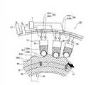
如图1所示,风力涡轮发电机100包括通过风旋转的转子10,用于增大转子10的转速的液压传动装置11、用于产生电力的发电机12、机舱14和用于支撑机舱14的塔架15。As shown in FIG. 1 , a
转子10构造成使得旋转轴18(等同于液压泵的旋转轴)连接至带有叶片16的轮毂17。具体地,三个叶片16从轮毂17径向延伸出,并且每个叶片16安装在连接到旋转轴18的轮毂17上。由此,作用在叶片16上的风能旋转作为整体的转子10,转子10的旋转经由旋转轴18输入液压传动装置11。轮毂17可以容纳用于改变叶片16的俯仰角度的俯仰驱动机构。The
液压传动装置11包括通过旋转轴18旋转的变量式的液压泵20、经由曲柄轴31连接到发电机20的变量式的液压马达21、和布置在液压泵20和液压马达21之间的高压油路22和低压油路23。高压油路22连接液压泵20的出口侧和液压马达21的入口侧。低压油路23连接液压马达21的出口侧和液压泵20的入口侧。由此,旋转轴18的旋转带动液压泵20旋转,从而形成了高压油路22和低压油路23之间的压差。所述压差驱动液压马达21。液压传动装置11根据旋转轴18的转速调整增速比(液压泵20和液压马达21的排量比),以保持液压马达21的转速为固定的速度。稍后详细描述所述液压传动装置。The
发电机12连接至液压传动装置11的液压马达21。发电机12可以使用已知的同步发电机或者感应发电机。转速基本上不变的扭矩从液压马达21输入发电机12,然后发电机12产生了频率基本上不变的交流电。The generator 12 is connected to the
机舱14旋转地支撑转子10的轮毂17,并容纳各种装置,例如液压传动装置11和发电机12。另外,机舱14旋转地支撑在塔架15上,并且可以由偏转马达(未示出)根据风向转动。Nacelle 14 rotatably supports
另外,测量旋转轴18的转速的转速测量仪40、测量高压油路22中的压力的第一压力测量仪41、测量高压油路22中的液压油的温度的温度传感器39设置在风力涡轮发电机100中。转速测量仪40和第一压力测量仪41的测量结果被传送至控制器1,以控制液压泵20和液压马达21。In addition, the rotational
控制器1控制风力涡轮发电机的每个部件。各种信号输入控制器1,输入信号例如转速测量仪的转速信号、第一压力测量仪41的高压油信号、温度传感器39的液压油温度信号、稍后描述的蓄能器的压力信号、液压泵20的转速信号和液压马达21的转速信号。可以基于上述的至少一个输入信号来控制高压阀65,85、低压阀66,86、蓄能器阀31,32、高压泄压阀37和低压泄压阀47。控制器1包括各种控制装置,并且控制器1和这种控制装置可以定位在不同的位置,即机舱14的外部或内部,使得控制器1可以形成分布式的控制系统。还可以的是,控制装置和控制器1中的不止一项功能可以结合入计算机处理单元中。The
蓄能器33,34经由蓄能器阀门31,32连接至高压油路22。蓄能器31,32例如可以是囊式或活塞式,其中空气和液压流体通过可变形的包分开。在蓄能器33,34中,高压的液压油在蓄能过程中被引入,以使囊变形或推动活塞来压缩空气。相反地,在压力释放过程中,压缩的空气膨胀或者来自外部的高压空气推动囊或活塞,以将液压油推出蓄能器33,34。The
第二压力测量仪(未示出)设置在蓄能器阀门31,32和蓄能器33,34之间。第二压力测量仪测量蓄能器33,34中的液压油的压力。A second pressure gauge (not shown) is arranged between the
第一压力传感器41和第二压力传感器的测量结果被传送至控制器1,以用于控制蓄能器阀门31,32的打开和关闭。优选地,控制器1基于第一压力传感器41和第二压力传感器的测量结果来控制蓄能器阀门31,32的打开和关闭。以此方式,蓄能器阀门31,32的打开和关闭被控制,以使蓄能器33,34与高压油路22连通或不连通。由此,可以保存输入液压传动装置11的多余的能量,并且当输出电力不足时释放该多余的能量,从而实现用易波动的风力能稳定地发电。The measurement results of the
旁通通路36设置在高压油路22和低压油路23之间。并且,高压泄压阀37设置在旁通通路70中,以保持高压油路22中的液压油的压力不高于设定的压力。以此方式,当高压油路22中的压力升高至高压泄压阀37的设定压力时,高压泄压阀37自动地打开以经由旁通通路36将高压油释放至低压油路23。The
另外,液压传动装置11具有油箱42、补给管路43、增压泵44、油过滤器45、返回管路46和低压泄压阀47。从液压马达22返回的全部或部分回流通过这些单元中的至少一个。In addition, the
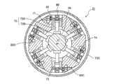
如图2所示,液压泵20具有多个由缸51和活塞52包围的工作腔53、凸轮表面与活塞52接合的凸轮58、连接每个工作腔53和高压油路22的高压总管60、连接每个工作腔和低压油路23的低压总管62、以及多组高压阀65和低压阀66,其中为每个工作腔53设置有一组高压阀65和低压阀66。As shown in FIG. 2, the
缸51为形成在稍后描述的缸体中的圆柱形空间。由缸51和活塞52包围的工作腔53形成在缸51内部。The
从活塞52平滑地沿着凸轮58的凸轮表面运行的观点看,活塞52中的每个优选地包括活塞主体52A和活塞滚子或活塞滑脚,其中活塞主体52A在缸51中滑动地移动,滚子或活塞滑脚安装在活塞主体52A上并与凸轮58的凸轮表面接合。“活塞滚子”为与凸轮58的凸轮表面接触并在其上滚动的构件。“活塞滑脚”为与凸轮58的凸轮表面接触并在其上滑动的构件。From the viewpoint that the
图2示出的示例中,示出活塞52中的每个活塞具有活塞主体52A和活塞滚子52B。In the example shown in FIG. 2 , each of the
凸轮58经由凸轮架59安装在旋转轴18的外圆周上。对于旋转轴18的一次旋转,凸轮58使液压泵20的每个活塞52上下移动很多次,从而增大液压泵20的扭矩。从这个观点看,凸轮58优选地为环状凸轮,其具有的凸轮表面限定了多个具有凹部58A和凸部58B的波浪形,凹部58A和凸部58B交替地设置在旋转轴18周围。The
凸轮58通过诸如螺栓、键和销的紧固构件57固定至凸轮架59。The
高压总管60包括多个第一分支通道60A和第一合并通道60B,其中第一分支通道60A各自连接至工作腔53,第一合并通道60B连接至高压油路22。第一分支通道60A连结到一起然后并入第一合并通道60B中。The high-pressure
低压总管62包括多个第二分支通道62A和第二合并通道62B,其中第二分支通道62A各自连接至工作腔53,第二合并通道62B连接至低压油路23。第二分支通道62A连结到一起然后并入第二合并通道62B中。The low-pressure
高压阀65布置在高压总管60的第一分支通道60A中,而低压阀66布置在低压总管62的第一分支通道62A中。通过打开和关闭高压阀65和低压阀66,可以改变高压油路22和每个工作腔53之间以及低压油路23和每个工作腔53之间的连通状态。高压阀65和低压阀66的打开和关闭与活塞52的向上和向下运动同步地进行。The high-
优选地,当工作腔53中的压力超过高压油路22中的压力时,高压阀65打开以允许液压油通过高压总管60从液压泵20的工作腔53流向高压油路22。优选地,当工作腔53中的压力下降到低压油路23中的压力以下时,低压阀66打开以允许液压油通过低压总管62从低压油路23流向液压泵20的工作腔53。由此,可以除去复杂的阀门控制,从而简化了控制。Preferably, when the pressure in the working
另外,优选地,液压泵的低压阀66为常开的电磁关闭阀,当工作腔53中的压力小于低压油路23中的压力时其被动地打开。以此方式,当工作腔中的压力小于低压油路23中的压力时,每个低压阀66被动地打开,从而节省了激励阀门所需要的电力。当工作腔53中的压力不当地增大时,低压阀66被释放,从而防止工作腔53中的压力异常地上升。In addition, preferably, the
在液压泵20中,当凸轮58随着旋转轴18旋转时,每个活塞52的活塞主体52A周期性地上下移动。在液压泵20中,重复地执行泵送步骤和吸入步骤,其中在泵送步骤中活塞52从下死点移动至上死点,在吸入步骤中活塞52从上死点移动至下死点。在泵送步骤中,高压阀65被打开并且低压阀66被关闭,以将工作腔53中的高压油依次通过第一分支通道60A和第一合并通道60B给送至高压油路22。同时,在吸入步骤中,高压阀65被关闭并且低压阀66被打开,以将来自低压油路23的低压油依次通过第二合并通道62B和第二分支通道62A供给至工作腔53。In the
以此方式,液压泵20随着旋转轴18的旋转而旋转,从而在高压油路22和低压油路23之间产生了压差。In this way, the
如图3所示,液压马达21包括多个形成在缸71和活塞72之间的液压腔73、凸轮表面与活塞72接合的凸轮78、连接每个工作腔73和高压油路22的高压总管80、连接每个工作腔73和低压油路23的低压总管82、以及为每个工作腔73设置的高压阀85和低压阀86。As shown in FIG. 3 , the
缸71为设置在稍后描述的缸体中的圆柱形空间。由缸71和活塞72包围的工作腔73形成在缸71内部。The
从将活塞72的上下运动平滑地转换成凸轮78的旋转运动的观点看,优选地,每个活塞72包括活塞主体72A和活塞滚子或活塞滑脚72C,活塞主体72A在缸71中滑动地移动,活塞滚子或活塞滑脚72C安装在活塞主体72A上并与凸轮78的凸轮表面接合。这里,“活塞滚子”为与凸轮78的凸轮表面接触并在其上转动的构件。“活塞滑脚”为与凸轮78的凸轮表面接触并在其上滑动的构件。From the viewpoint of smoothly converting the up and down movement of the
凸轮78为偏心凸轮,其相对于连接至发电机12的曲柄轴13的轴中心O偏心地设置。当活塞72完成一组上下运动时,凸轮78和凸轮78安装在其上的曲柄轴13完成了一次旋转。The
高压总管80包括多个第一分支通道80A和第一合并通道80B,其中第一分支通道80A各自连接至工作腔73,第一合并通道80B连接至高压油路22。第一分支通道80A连结到一起然后并入第一合并通道80B中。The high pressure
低压总管82包括多个第二分支通道82A和第二合并通道82B,其中第二分支通道82A各自连接至工作腔73,第二合并通道82B连接至低压油路23。第二分支通道82A连结到一起然后并入第二合并通道82B中。The low pressure
高压阀85布置在高压总管80的第一分支通道80A中,而低压阀86布置在低压总管82的第一分支通道82A中。通过打开和关闭高压阀85和低压阀86,可以改变高压油路22和每个工作腔73之间以及低压油路23和每个工作腔73之间的连通状态。高压阀85和低压阀86的打开和关闭与活塞72的向上和向下移动同步地进行。The high-
在液压马达21中,通过利用高压油路22和低压油路23之间的压差使活塞72向上和向下移动。在液压马达21中,重复地执行致动(motor)步骤和排出步骤,其中在致动步骤中活塞72从上死点移动至下死点,在排出步骤中活塞72从下死点移动至上死点。在致动步骤中,高压阀85被打开并且低压阀86被关闭,以将来自高压油路22的高压的液压油(高压油)依次通过高压总管80的第一合并通道80B和第一分支通道80A供给至工作腔73。同时,在排出步骤中,高压阀85被关闭并且低压阀86被打开,以将工作腔73中的液压油依次通过低压总管82的第一分支通道82A和第一合并通道82B排出至低压油路23。In the
以此方式,在致动步骤中给送入工作腔73中的高压油将活塞72向下推至下死点,然后曲柄轴13和凸轮78一起旋转。In this way, the high-pressure oil fed into the working
在上述液压传动装置中,液压泵20和液压马达21的高压阀65,85和低压阀66,86中的至少一个可以是压力操纵的单向阀,其能够由通过高压阀65,85和低压阀66,86中的至少一个上的压差而打开,以允许液压油沿一个方向流动。以此方式,由所述压差打开和关闭的单向阀用在液压泵20和液压马达21的高压阀65,85和低压阀66,86中的至少一个上,从而节省了用于打开和关闭阀门的电力,并且还降低了运行成本。另外,允许液压油沿一个方向流动,从而防止了液压油回流。In the above-mentioned hydraulic transmission device, at least one of the high-
另外,液压泵20和液压马达21的高压阀65,85和低压阀66,86中的至少一个可以是电子控制阀,控制器1可以控制与活塞运动的循环阶段相关的电子控制阀的打开和关闭,以在每个循环中调节工作腔53,73排出的液压油的净体积量。在这样的情况中,控制器1可以改变处于空转状态的工作腔53,73的数目,以在每个工作循环中调节工作腔53,73排出的液压油的净体积量,在活塞运动的整个循环中,处于空转状态的工作腔53,73的低压阀66,86保持打开。以此方式,改变处于空转状态的工作腔53,73的数目来调整工作腔53,73排出的液压油的体积,从而渐进地控制排量,并使得控制相对较容易。In addition, at least one of the high-
控制器1还可以在活塞运动的每个循环中改变至少一组低压阀66,86和高压阀65,86的关闭时间,以在每个循环中调节工作腔53,73排出的液压油的净体积量,对属于所述至少一组低压阀66,86和高压阀65,86中的全部阀门,关闭时间被共同改变。以此方式,相同组的阀的关闭时间被同步,从而提高控制稳定性,并使得较容易获知维护的时间。The
此外,液压泵20和液压马达21的低压阀66,86和高压阀65,86中的至少一个可以是电子控制阀。所述电子控制阀为规定压力下不能打开的面密封提升阀。In addition, at least one of the low-
此外,液压泵20和液压马达21的低压阀66,86和高压阀65,86中的至少一个可以是电子控制阀,并且控制器1可以控制电子控制阀的打开和关闭,以在活塞的每个运动循环期间阻止液压油的不对称流出工作腔53,73引起的流动和扭矩的波动。以此方式,不对称流引起的流动和扭矩的波动被抑制,从而实现了稳定的运行。In addition, at least one of the low-
现在阐述本发明的风力涡轮发电机的液压传动装置11的具体结构。The specific structure of the
(液压泵结构)(hydraulic pump structure)
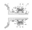
图4至图8示出了液压泵的结构。图4为示出了液压泵的具体结构的剖视图。图5为沿着图4的线A-A截取的剖视图。图6为沿着图5的线B-B截取的剖视图,示出了液压泵的缸体。图7为从图4的方向C观察缸体的平面视图。图8为沿着图4的线D-D截取的剖视图,示出了液压泵的端板(endplate)。4 to 8 show the structure of the hydraulic pump. Fig. 4 is a sectional view showing a specific structure of the hydraulic pump. FIG. 5 is a cross-sectional view taken along line A-A of FIG. 4 . FIG. 6 is a sectional view taken along line B-B of FIG. 5, showing a cylinder of a hydraulic pump. Fig. 7 is a plan view of the cylinder viewed from direction C in Fig. 4 . Fig. 8 is a sectional view taken along line D-D of Fig. 4, showing an endplate of the hydraulic pump.
如图4和图5所示,液压泵20安装在旋转轴18上。具体地,凸轮架59固定到旋转轴18的外周面,并且凸轮58安装在凸轮架59上。此外,在图4所示的示例中,液压泵20布置在用于在机舱侧部上旋转地支撑旋转轴18的旋转轴轴承19A和19B之间。As shown in FIGS. 4 and 5 , a
泵壳体50经由泵轴承55固定在凸轮架59的外周上。泵壳体50覆盖缸51、活塞52、高压总管60、低压总管62、高压阀65(见图6)、低压阀66和凸轮58中的每个部件,并且还防止液压油漏到外部。泵壳体50包括沿旋转轴18的轴向布置的一对端板50A和50B以及布置在所述这对端板50A和50B之间的圆柱形壳体50C。The
液压泵20可以包括多个模块,每个模块由具有至少一个缸51的缸体54、活塞52、高压总管60、低压总管62以及为缸体54的每个缸51设置的高压阀65和低压阀66构成。所述模块由缸体54和诸如活塞52、高压阀65和低压阀66的附加部件形成。The
如图6所示,缸体54中的每个缸体为在横截面中沿旋转轴18的周向或旋转中心轴线的方向延伸的圆弧形构件。As shown in FIG. 6 , each of the
当缸体54沿旋转轴18的旋转中心轴线的方向延伸时,缸体54中的每个缸体包括至少一个缸阵列56。缸体54中的每个缸体由沿旋转轴18的轴向方向布置的缸51-1、51-2、51-3和51-4构成。在缸体54中,为每个缸51布置有一对活塞52、高压阀65和低压阀66(见图6)。When the
如图5所示,液压泵20包括沿旋转轴18的周向布置的多个模块,每个模块由圆弧形的缸体54、活塞52、以及为缸体54的每个缸51设置的高压阀65和低压阀66构成。As shown in FIG. 5 , the
多个缸阵列56沿旋转轴18的周向布置在缸体54中。多个第一分支通道60A自每个缸51沿中心旋转轴线的周向形成在缸体54内部。高压连通通道60C也在缸体内沿图7所示的旋转轴线的方向设置在相邻的两个缸阵列之间。设置在相同阵列中的第一分支通道60A经由高压阀65连接至高压连通通道60C。在这样的情况下,第一分支通道60A可以连接至属于相邻的两个缸阵列56的缸51的工作腔53。A plurality of
高压连通通道60C延伸至端板50B,并且如图8所示,连接至形成在端板50B中的第一合并通道60B。高压连通通道60C具有沿旋转中心轴线的周向形成在端板50B中的开口。该开口与第一合并通道60B流体连通。第一合并通道60B形成为沿着旋转中心轴线的周向的环形,并且连接至至少一个高压油路22。在图中第一合并通道形成为圆环形。然而,这不是限制性的,第一合并通道60B可以形成为任何形状,例如矩形环形。The high-
以此方式,高压总管60的第一合并通道60B设置在形成泵壳体50的端面的端板50B内部。由此,可以防止高压的液压油泄漏,从而提高液体密封性。In this way, the first
此外,第一分支通道60B经由形成在相邻的两个缸阵列之间的高压连通通道60C与第一合并通道60A流体连通。由此,可以简化油路的结构,从而节省了空间。Further, the
在优选实施例中,第一分支通道60B经由高压连通通道60C与第一合并通道60A流体连通。然而,这不是限制性的,第一分支通道60B可以直接连接至第一合并通道60A。在优选实施例中,具有圆弧形横截面的多个缸体54沿旋转中心轴线的周向布置。然而,这不是限制性的,也可以沿周向布置具有环形横截面的缸体。In a preferred embodiment, the
根据以上的结构,工作腔53压出的高压油被引导通过第一分支通道60A,然后通过连接至端板50B的高压油路22的第一合并通道60B。According to the above structure, the high-pressure oil pressed out of the working
如图4至图6所示,低压总管62沿旋转轴18的径向方向布置在缸体54的外侧,并且布置在泵壳体50的内侧。低压总管62包括沿旋转轴18的径向方向延伸在工作腔53的外侧的第二分支通道62以及形成在缸体54的外周和泵壳体50之间的第二合并通道62B。As shown in FIGS. 4 to 6 , the low-
低压阀66布置在第二分支通道62A中。第二合并通道62B设置用于多个缸51,并且与连接至液压泵20的上部的低压油路23流体连通。以此方式,低压油路23的低压油依次通过第二合并通道62B和第二分支通道62A经由低压阀66供给至各个工作腔53。A low-
如上所述,第一分支通道60A和第二分支通道62A形成在缸体54的内部。由此,不必再安装从工作腔53分别至第一和第二合并通道60B、62B的管路,从而减小了液压泵20的尺寸。As described above, the
此外,低压总管62的第二合并通道62B形成在泵壳体50和缸体54之间的环状空间中。由此,可以利用泵壳体50和缸体54之间的空间,从而节省了空间并简化了管路的结构。Furthermore, a second
(液压马达结构)(hydraulic motor structure)
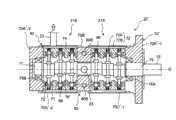
图9至图12示出了液压马达的结构。图9为示出了液压马达的具体结构的剖视图。图10为沿着图9的线E-E截取的剖视图。图11为沿着图9的线F-F截取的液压马达的端板的剖视图。图12为液压马达的外部透视图。9 to 12 show the structure of the hydraulic motor. Fig. 9 is a sectional view showing a specific structure of the hydraulic motor. FIG. 10 is a cross-sectional view taken along line E-E of FIG. 9 . 11 is a cross-sectional view of the end plate of the hydraulic motor taken along line F-F of FIG. 9 . Fig. 12 is an external perspective view of the hydraulic motor.
如图9和图10所示,液压马达21的凸轮78为偏心凸轮,其相对于经由轴连接部75连接至发电机12的曲柄轴13的轴中心O偏心地设置。As shown in FIGS. 9 and 10 , the
马达壳体70经由凸轮轴承76A,76B固定到轴连接部75和凸轮端部77,其中凸轮端部77和轴连接部77分别连接至凸轮78的每个端部。马达壳体70覆盖缸71、活塞72、高压总管80、低压总管82、高压阀85、低压阀86和凸轮78中的每个部件,并且还防止液压油泄漏到外部。马达壳体70包括沿曲柄轴13的轴向布置的一对端板70A和70B以及布置在所述这对端板70A和70B之间的圆柱形壳体70C(见图12)。The
环绕凸轮78形成的缸体74设置在液压马达21中。缸体74包括至少一个缸71、一对活塞72和为至少一个缸71中的每个缸设置的高压阀85和低压阀86。此外,在图10所示的示例中,活塞72包括活塞主体72A和活塞滑脚72C,活塞主体72A在缸71中滑动地移动,活塞滑脚72C安装在活塞主体72A上并与凸轮78的凸轮表面接合。A
液压马达21可以包括沿曲柄轴13的周向布置的多个模块。每个模块可以由部分地覆盖凸轮78的凸轮表面的缸体74、为缸体74的每个缸71设置的活塞72以及为缸体74的至少一个缸71中的每个缸设置的高压阀85和低压阀86构成。The
所述模块可以由以连续方式围绕曲柄轴13的中心轴线O周向配置的缸体74和附接到缸体74的部件组构成,其中,所述部件组例如活塞72、高压阀85和低压阀86。The module may consist of a
缸体74中的每个缸体为沿凸轮78的旋转中心轴线的方向或周向延伸的构件。Each of the
当缸体74沿旋转中心轴线的方向延伸时,缸体74中的每个缸体包括至少一个缸阵列,该缸阵列包括沿凸轮78的轴向布置的多个缸71。在缸体74中,为每个缸71布置一对活塞72、高压阀85和低压阀86。When the
液压马达21包括沿凸轮78的周向布置的多个模块,其中每个模块由圆弧形的缸体74、活塞72、以及为缸体74的每个缸71设置的高压阀85和低压阀86构成。The
多个缸阵列沿凸轮78的周向布置在缸体74中。多个第一分支通道80A自每个缸71沿中心旋转轴线的周向形成在缸体74内部。高压连通通道80C也在缸体74内部沿旋转轴线的方向布置在相邻的两个缸阵列之间,与图7所示的液压泵20的结构相似。设置在相同阵列中的第一分支通道80A经由高压阀85连接至高压连通通道80C。在这样的情况下,第一分支通道80A可以连接至属于相邻的两个缸阵列的缸71的工作腔73。A plurality of cylinder arrays are arranged in the
高压连通通道80C延伸至端板70B,并且如图11所示,连接至形成在端板70B中的第一合并通道80B。高压连通通道80C具有沿旋转中心轴线的周向形成在端板70B中的开口。该开口与第一合并通道80B流体连通。第一合并通道80B形成为沿着旋转中心轴线的周向的环形,并且连接至至少一个高压油路22。在图中第一合并通道形成为矩形环形。然而,这不是限制性的,第一合并通道80B可以形成为任何形状,例如圆环形。The high-
以此方式,高压总管80的第一合并通道80B设置在形成泵壳体70的端面的端板70B内部。由此,可以防止高压的液压油泄漏,从而提高液体密封性。In this way, the first
此外,第一分支通道80B经由形成在相邻的两个缸阵列之间的高压连通通道80C与第一合并通道80A流体连通。由此,可以简化油路的结构,从而节省了空间。Further, the
在优选实施例中,第一分支通道80B经由高压连通通道80C与第一合并通道80A流体连通。然而,这不是限制性的,第一分支通道80B可以直接连接至第一合并通道80A。In a preferred embodiment, the
如上所述,液压传动装置包括液压泵12、液压马达14、高压油路16和低压油路18。液压泵12的出口侧连接至液压马达14的入口侧,并且液压泵12的入口侧连接至液压马达14的出口侧。As mentioned above, the hydraulic transmission device includes a hydraulic pump 12 , a hydraulic motor 14 , a high-
在图中,液压传动装置11示出为仅具有一个液压马达21。然而,液压传动装置11可以包括多于一个的液压马达21,并且液压马达21可以分别经由高压油路22和低压油路23连接至液压泵21。In the figures, the
根据以上的结构,由液压泵20供给的高压油从连接至液压马达21的端板70B的高压油路22被引导通过第一合并通道80B、并然后通过高压总管80的第一分支通道80A引至工作腔73。According to the above structure, the high-pressure oil supplied by the
低压总管82沿凸轮78的径向布置在缸体74的外侧,并且布置在马达壳体70的内侧。低压总管82包括沿凸轮78的径向延伸在工作腔73的外侧的第二分支通道82以及形成在缸体74的外周和马达壳体70之间的第二合并通道82B。The low-
低压阀76布置在第二分支通道82A中。第二合并通道82B设置用于多个缸71,并且与连接至液压马达21的上部的低压油路23流体连通。以此方式,工作腔73排出的低压油经由低压阀86通过低压总管82的第二分支通道82A并然后通过第二合并通道82B被供给至每个工作腔73。The low-pressure valve 76 is arranged in the second branch passage 82A. The
如上所述,第一分支通道80A和第二分支通道82A形成在缸体74的内部。由此,不必再安装从工作腔73分别至第一和第二合并通道80B、82B的管路,从而减小了液压马达21的尺寸。As described above, the
此外,低压总管82的第二合并通道82B形成在马达壳体70和缸体74之间的环状空间中。由此,可以利用马达壳体70和缸体74之间的空间,从而节省了空间并简化了管路的结构。Furthermore, a second
图13示出了以上的液压马达的改型示例。对于与上述液压马达的部件相同的部件采用了相同的附图标记。Fig. 13 shows a modified example of the above hydraulic motor. The same reference numerals are used for the same components as those of the hydraulic motor described above.
图13示出了双马达类型的液压马达21'。液压马达21'包括经由端板70B'连接的两个马达单元2lA和2lB。马达单元2lA和2lB中的每个包括缸71、活塞72、高压总管80、低压总管82、高压阀85(见图10)和低压阀86。马达单元2lA和21B容纳在壳体70'中。壳体70'包括端板70A'-1,70A'-2、端板70B'和圆柱形壳体70'C-l或70'C-2,其中端板70A'-1,70A'-2沿液压马达21'的中心轴线方向设置在液压马达21'的两个端部上,端板70B'设置在端板70A'-1和70A'-2之间,圆柱形壳体70'C-l或70'C-2设置在端板70A'-1或70A'-2和端板70B'之间。马达单元2lA和2lB具有穿透端板70B'的凸轮78'。高压总管80的第一合并通道80B可以设置在端板70B'中,并且第一合并通道80可以构造成由两个马达单元2lA和21B使用,从而简化了管路结构。Fig. 13 shows a hydraulic motor 21' of the dual motor type. The hydraulic motor 21' comprises two
如上所述,在优选实施例中,高压阀65,85布置在连接至工作缸53,73的第一分支通道60A,80A中,并且低压阀66,86布置在第二分支通道62A,82A中。由此,可以根据传送至液压传动装置11的控制信号非常准确的调节所述阀。这即使在可再生能的波动中也能获得较高的发电效率。As mentioned above, in the preferred embodiment the
此外,图4至图8中的液压泵20的泵壳体50和图9至图12中的液压马达21的马达壳体70容纳工作腔53,73、高压总管60,80、低压总管62,82、高压阀65,85和低压阀66,86,从而减小了装置的尺寸。Furthermore, the
特别地,液压泵20的高压总管60通过没有任何干预阀的高压油路22直接连接至液压马达21的高压总管80,从而在没有引起能量损失的情况下高效地发电。In particular, the
尽管已经参考示例性的实施例描述了本发明,然而对本领域技术人员显而易见的是,可以做出没有偏离本发明的范围的各种改变。While the invention has been described with reference to exemplary embodiments, it will be apparent to those skilled in the art that various changes may be made without departing from the scope of the invention.
例如,上述优选实施例使用了应用本发明的示例性的情形。然而,本发明还可以应用于潮流发电机。这里的潮流发电机指的是安装在诸如海洋、河流和湖泊的地方、利用潮流能产生电力的发电装置。除了转子10是由潮流转动而不是风转动外,潮流发电机具有与风力涡轮发电机1相同的基本结构。这里使用相同的附图标记来说明与风力涡轮发电机100共同的部件。潮流发电机包括由接收到的潮流转动的转子10、用于增加转子10转速的液压传动装置11、用于产生电力的发电机12。For example, the preferred embodiments described above use exemplary scenarios for applying the present invention. However, the invention can also be applied to tidal current generators. The tidal current generator here refers to a power generation device installed in places such as oceans, rivers, and lakes to generate electricity using tidal current energy. The tidal current generator has the same basic structure as the
如上所述,潮流发电机的液压传动装置11构造成,使得高压阀65,85布置在连接至工作缸53,73的第一分支通道60A,80A中,并且低压阀66,86布置在第二分支通道62A,82A中。由此,可以根据传送至液压传动装置11的控制信号非常准确地调节阀。这即使在可再生能的波动中也能获得较高的发电效率。As described above, the
此外,液压泵20的泵壳体50和液压马达21的马达壳体70容纳工作腔53,73、高压总管60,80、低压总管62,82、高压阀65,85和低压阀66,86,从而减小了装置的尺寸。Furthermore, the
附图标记reference sign
1 控制器1 controller
10 转子10 rotors
11 液压传动装置11 hydraulic transmission
12 发电机12 Generators
13 曲柄轴13 crankshaft
18 旋转轴18 axis of rotation
20 液压泵20 hydraulic pump
21 液压马达21 hydraulic motor
22 高压油路22 High pressure oil circuit
23 低压油路23 Low pressure oil circuit
31,32 蓄能器阀31,32 Accumulator valve
33,34 蓄能器33,34 accumulator
36 旁通通路36 bypass path
37 高压减压阀37 High pressure pressure reducing valve
38 第二压力测量仪38 Second pressure gauge
40 转速测量仪40 speed measuring instrument
41 第一压力测量仪41 The first pressure gauge
50 泵壳体50 pump housing
50A,50B,70A,70B 端板50A,50B,70A,70B end plate
50C,70C 圆周形壳体50C,70C Circumferential shell
51,71 缸51,71 cylinder
52,72 活塞52,72 piston
53,73 工作腔53,73 working chamber
58,78 凸轮58,78 cam
60,80 高压总管60,80 High Pressure Mains
60A,80A 第一分支通道60A, 80A first branch channel
60B,80B 第一合并通道60B, 80B first merge channel
62A,82A 第二分支通道62A, 82A second branch channel
62B,82B 第二合并通道62B, 82B second merge channel
65,85 高压阀65,85 High pressure valve
66,86 低压阀66,86 Low pressure valve
Claims (19)
Translated fromChineseApplications Claiming Priority (15)
| Application Number | Priority Date | Filing Date | Title |
|---|---|---|---|
| GB1009013.2 | 2010-05-28 | ||
| GB1009012.4AGB2480683B (en) | 2010-05-28 | 2010-05-28 | Method and apparatus for extracting energy from a fluctuating energy flow from a renewable energy source |
| GB1009012.4 | 2010-05-28 | ||
| GB1009013AGB2480684A (en) | 2010-05-28 | 2010-05-28 | A method and apparatus for operating a renewable energy extraction device |
| JPPCT/JP2010/006979 | 2010-11-30 | ||
| PCT/JP2010/006978WO2012073278A1 (en) | 2010-11-30 | 2010-11-30 | Wind turbine generator |
| PCT/JP2010/006981WO2012073280A1 (en) | 2010-11-30 | 2010-11-30 | Hydraulic pump structure for wind turbine generator or tidal current generator and method of mounting hydraulic pump |
| JPPCT/JP2010/006981 | 2010-11-30 | ||
| JPPCT/JP2010/006982 | 2010-11-30 | ||
| JPPCT/JP2010/006978 | 2010-11-30 | ||
| PCT/JP2010/006979WO2012073279A1 (en) | 2010-11-30 | 2010-11-30 | Wind turbine generator system and operation control method thereof |
| PCT/JP2010/006982WO2012073281A1 (en) | 2010-11-30 | 2010-11-30 | Wind turbine generator or tidal current generator and operation method thereof |
| JPPCT/JP2010/006977 | 2010-11-30 | ||
| PCT/JP2010/006977WO2012073277A2 (en) | 2010-11-30 | 2010-11-30 | Wind turbine generator and tidal current generator |
| PCT/JP2011/003002WO2011148653A2 (en) | 2010-05-28 | 2011-05-30 | Power generating apparatus of renewable energy type |
Publications (2)
| Publication Number | Publication Date |
|---|---|
| CN102884314Atrue CN102884314A (en) | 2013-01-16 |
| CN102884314B CN102884314B (en) | 2016-11-30 |
Family
ID=
Cited By (2)
| Publication number | Priority date | Publication date | Assignee | Title |
|---|---|---|---|---|
| CN104564508A (en)* | 2015-01-12 | 2015-04-29 | 郑涵文 | Tidal power generation device |
| CN107023632A (en)* | 2016-02-01 | 2017-08-08 | 熵零控股股份有限公司 | A kind of energy adjustment system |
Citations (5)
| Publication number | Priority date | Publication date | Assignee | Title |
|---|---|---|---|---|
| DE1653420A1 (en)* | 1968-01-18 | 1971-12-23 | Immeyer Kurt Guenter | Hydraulic motor with power-driven eccentric shaft |
| US4496847A (en)* | 1982-06-04 | 1985-01-29 | Parkins William E | Power generation from wind |
| WO1991005163A1 (en)* | 1988-09-29 | 1991-04-18 | The University Of Edinburgh | Improved fluid-working machine |
| US20090155095A1 (en)* | 2007-12-18 | 2009-06-18 | Sauer-Danfoss Inc. | Radial piston pump |
| US20100040470A1 (en)* | 2008-08-13 | 2010-02-18 | Jacob Johannes Nies | Wind energy system with fluid-working machine with non-symmetric actuation |
Patent Citations (5)
| Publication number | Priority date | Publication date | Assignee | Title |
|---|---|---|---|---|
| DE1653420A1 (en)* | 1968-01-18 | 1971-12-23 | Immeyer Kurt Guenter | Hydraulic motor with power-driven eccentric shaft |
| US4496847A (en)* | 1982-06-04 | 1985-01-29 | Parkins William E | Power generation from wind |
| WO1991005163A1 (en)* | 1988-09-29 | 1991-04-18 | The University Of Edinburgh | Improved fluid-working machine |
| US20090155095A1 (en)* | 2007-12-18 | 2009-06-18 | Sauer-Danfoss Inc. | Radial piston pump |
| US20100040470A1 (en)* | 2008-08-13 | 2010-02-18 | Jacob Johannes Nies | Wind energy system with fluid-working machine with non-symmetric actuation |
Cited By (2)
| Publication number | Priority date | Publication date | Assignee | Title |
|---|---|---|---|---|
| CN104564508A (en)* | 2015-01-12 | 2015-04-29 | 郑涵文 | Tidal power generation device |
| CN107023632A (en)* | 2016-02-01 | 2017-08-08 | 熵零控股股份有限公司 | A kind of energy adjustment system |
Also Published As
| Publication number | Publication date |
|---|---|
| WO2011148653A2 (en) | 2011-12-01 |
| KR20130026439A (en) | 2013-03-13 |
| EP2454479B1 (en) | 2015-10-28 |
| US20130067900A1 (en) | 2013-03-21 |
| EP2454479A2 (en) | 2012-05-23 |
| WO2011148653A3 (en) | 2012-04-12 |
Similar Documents
| Publication | Publication Date | Title |
|---|---|---|
| EP2454479B1 (en) | Power generating apparatus of renewable energy type | |
| JP5383714B2 (en) | Wind power generator and tidal current power generator | |
| KR101355267B1 (en) | Fluid-working machine with multi-lobe ring cam | |
| CN102797613B (en) | A kind of water pumping compressed air energy-storage | |
| US8106527B1 (en) | Hydraulic power generator | |
| Tao et al. | Mechanical design and numerical simulation of digital-displacement radial piston pump for multi-megawatt wind turbine drivetrain | |
| JP5818967B2 (en) | Renewable energy generator with hydraulic pump capable of operation in motoring mode | |
| US12352295B2 (en) | Variable output, hydraulic drive system | |
| CN102384055B (en) | Low-rotating-speed plunger pump device and wind power generation device applying same | |
| JP5331250B2 (en) | Renewable energy generator | |
| CN105971826B (en) | Fluid pressure type wind-driven generator | |
| US9677535B2 (en) | Pump turbine plant | |
| CN202273819U (en) | Low rotary speed plunger pump device and wind power generation device using same | |
| CN105637220A (en) | Gear pump for hydroelectric power generation | |
| CN104775984A (en) | Electro-hydraulic power generator and wind power electro-hydraulic power generating system | |
| CN105971981B (en) | Hydraulic power mechanism and fluid pressure type wind-driven generator | |
| CN102884314B (en) | Power generation device of renewable energy type | |
| Plagge et al. | Next-generation hydrokinetic power take-off via a novel variable-stroke hydraulic system | |
| US20110006524A1 (en) | Wind turbine with stable power output | |
| CN109882361A (en) | A kind of efforts of everyone fluid power generation device and its energy storage device | |
| RU2761706C1 (en) | Method for increasing the installed capacity coefficient of a wind farm | |
| RU69931U1 (en) | HYDRAULIC UNIT FAST EFFICIENCY | |
| CN201090378Y (en) | Hydraulic pressure energy collecting wind power generation system | |
| KR20100053053A (en) | A fluid mechanic generating apparatus | |
| CN109458287A (en) | A kind of hydraulic turbine synchronizing filling medium |
Legal Events
| Date | Code | Title | Description |
|---|---|---|---|
| C06 | Publication | ||
| PB01 | Publication | ||
| C10 | Entry into substantive examination | ||
| SE01 | Entry into force of request for substantive examination | ||
| C14 | Grant of patent or utility model | ||
| GR01 | Patent grant | ||
| CF01 | Termination of patent right due to non-payment of annual fee | ||
| CF01 | Termination of patent right due to non-payment of annual fee | Granted publication date:20161130 Termination date:20200530 |