CN102883880A - Lamination of electrochromic devices to glass substrates - Google Patents
Lamination of electrochromic devices to glass substratesDownload PDFInfo
- Publication number
- CN102883880A CN102883880ACN2011800133262ACN201180013326ACN102883880ACN 102883880 ACN102883880 ACN 102883880ACN 2011800133262 ACN2011800133262 ACN 2011800133262ACN 201180013326 ACN201180013326 ACN 201180013326ACN 102883880 ACN102883880 ACN 102883880A
- Authority
- CN
- China
- Prior art keywords
- glass
- electrochromic device
- substrate
- laminate
- outer laminated
- Prior art date
- Legal status (The legal status is an assumption and is not a legal conclusion. Google has not performed a legal analysis and makes no representation as to the accuracy of the status listed.)
- Granted
Links
Images


Classifications
- B—PERFORMING OPERATIONS; TRANSPORTING
- B32—LAYERED PRODUCTS
- B32B—LAYERED PRODUCTS, i.e. PRODUCTS BUILT-UP OF STRATA OF FLAT OR NON-FLAT, e.g. CELLULAR OR HONEYCOMB, FORM
- B32B17/00—Layered products essentially comprising sheet glass, or glass, slag, or like fibres
- B32B17/06—Layered products essentially comprising sheet glass, or glass, slag, or like fibres comprising glass as the main or only constituent of a layer, next to another layer of a specific material
- B32B17/10—Layered products essentially comprising sheet glass, or glass, slag, or like fibres comprising glass as the main or only constituent of a layer, next to another layer of a specific material of synthetic resin
- B32B17/10005—Layered products essentially comprising sheet glass, or glass, slag, or like fibres comprising glass as the main or only constituent of a layer, next to another layer of a specific material of synthetic resin laminated safety glass or glazing
- B32B17/10009—Layered products essentially comprising sheet glass, or glass, slag, or like fibres comprising glass as the main or only constituent of a layer, next to another layer of a specific material of synthetic resin laminated safety glass or glazing characterized by the number, the constitution or treatment of glass sheets
- B32B17/10036—Layered products essentially comprising sheet glass, or glass, slag, or like fibres comprising glass as the main or only constituent of a layer, next to another layer of a specific material of synthetic resin laminated safety glass or glazing characterized by the number, the constitution or treatment of glass sheets comprising two outer glass sheets
- B32B17/10045—Layered products essentially comprising sheet glass, or glass, slag, or like fibres comprising glass as the main or only constituent of a layer, next to another layer of a specific material of synthetic resin laminated safety glass or glazing characterized by the number, the constitution or treatment of glass sheets comprising two outer glass sheets with at least one intermediate layer consisting of a glass sheet
- B—PERFORMING OPERATIONS; TRANSPORTING
- B32—LAYERED PRODUCTS
- B32B—LAYERED PRODUCTS, i.e. PRODUCTS BUILT-UP OF STRATA OF FLAT OR NON-FLAT, e.g. CELLULAR OR HONEYCOMB, FORM
- B32B17/00—Layered products essentially comprising sheet glass, or glass, slag, or like fibres
- B32B17/06—Layered products essentially comprising sheet glass, or glass, slag, or like fibres comprising glass as the main or only constituent of a layer, next to another layer of a specific material
- B32B17/10—Layered products essentially comprising sheet glass, or glass, slag, or like fibres comprising glass as the main or only constituent of a layer, next to another layer of a specific material of synthetic resin
- B32B17/10005—Layered products essentially comprising sheet glass, or glass, slag, or like fibres comprising glass as the main or only constituent of a layer, next to another layer of a specific material of synthetic resin laminated safety glass or glazing
- B32B17/10165—Functional features of the laminated safety glass or glazing
- B32B17/10431—Specific parts for the modulation of light incorporated into the laminated safety glass or glazing
- B32B17/10467—Variable transmission
- B32B17/10495—Variable transmission optoelectronic, i.e. optical valve
- B32B17/10513—Electrochromic layer
- B—PERFORMING OPERATIONS; TRANSPORTING
- B32—LAYERED PRODUCTS
- B32B—LAYERED PRODUCTS, i.e. PRODUCTS BUILT-UP OF STRATA OF FLAT OR NON-FLAT, e.g. CELLULAR OR HONEYCOMB, FORM
- B32B17/00—Layered products essentially comprising sheet glass, or glass, slag, or like fibres
- B32B17/06—Layered products essentially comprising sheet glass, or glass, slag, or like fibres comprising glass as the main or only constituent of a layer, next to another layer of a specific material
- B32B17/10—Layered products essentially comprising sheet glass, or glass, slag, or like fibres comprising glass as the main or only constituent of a layer, next to another layer of a specific material of synthetic resin
- B32B17/10005—Layered products essentially comprising sheet glass, or glass, slag, or like fibres comprising glass as the main or only constituent of a layer, next to another layer of a specific material of synthetic resin laminated safety glass or glazing
- B32B17/10165—Functional features of the laminated safety glass or glazing
- B32B17/10174—Coatings of a metallic or dielectric material on a constituent layer of glass or polymer
- B—PERFORMING OPERATIONS; TRANSPORTING
- B32—LAYERED PRODUCTS
- B32B—LAYERED PRODUCTS, i.e. PRODUCTS BUILT-UP OF STRATA OF FLAT OR NON-FLAT, e.g. CELLULAR OR HONEYCOMB, FORM
- B32B17/00—Layered products essentially comprising sheet glass, or glass, slag, or like fibres
- B32B17/06—Layered products essentially comprising sheet glass, or glass, slag, or like fibres comprising glass as the main or only constituent of a layer, next to another layer of a specific material
- B32B17/10—Layered products essentially comprising sheet glass, or glass, slag, or like fibres comprising glass as the main or only constituent of a layer, next to another layer of a specific material of synthetic resin
- B32B17/10005—Layered products essentially comprising sheet glass, or glass, slag, or like fibres comprising glass as the main or only constituent of a layer, next to another layer of a specific material of synthetic resin laminated safety glass or glazing
- B32B17/1055—Layered products essentially comprising sheet glass, or glass, slag, or like fibres comprising glass as the main or only constituent of a layer, next to another layer of a specific material of synthetic resin laminated safety glass or glazing characterized by the resin layer, i.e. interlayer
- B32B17/10743—Layered products essentially comprising sheet glass, or glass, slag, or like fibres comprising glass as the main or only constituent of a layer, next to another layer of a specific material of synthetic resin laminated safety glass or glazing characterized by the resin layer, i.e. interlayer containing acrylate (co)polymers or salts thereof
- B—PERFORMING OPERATIONS; TRANSPORTING
- B32—LAYERED PRODUCTS
- B32B—LAYERED PRODUCTS, i.e. PRODUCTS BUILT-UP OF STRATA OF FLAT OR NON-FLAT, e.g. CELLULAR OR HONEYCOMB, FORM
- B32B17/00—Layered products essentially comprising sheet glass, or glass, slag, or like fibres
- B32B17/06—Layered products essentially comprising sheet glass, or glass, slag, or like fibres comprising glass as the main or only constituent of a layer, next to another layer of a specific material
- B32B17/10—Layered products essentially comprising sheet glass, or glass, slag, or like fibres comprising glass as the main or only constituent of a layer, next to another layer of a specific material of synthetic resin
- B32B17/10005—Layered products essentially comprising sheet glass, or glass, slag, or like fibres comprising glass as the main or only constituent of a layer, next to another layer of a specific material of synthetic resin laminated safety glass or glazing
- B32B17/1055—Layered products essentially comprising sheet glass, or glass, slag, or like fibres comprising glass as the main or only constituent of a layer, next to another layer of a specific material of synthetic resin laminated safety glass or glazing characterized by the resin layer, i.e. interlayer
- B32B17/10761—Layered products essentially comprising sheet glass, or glass, slag, or like fibres comprising glass as the main or only constituent of a layer, next to another layer of a specific material of synthetic resin laminated safety glass or glazing characterized by the resin layer, i.e. interlayer containing vinyl acetal
- B—PERFORMING OPERATIONS; TRANSPORTING
- B32—LAYERED PRODUCTS
- B32B—LAYERED PRODUCTS, i.e. PRODUCTS BUILT-UP OF STRATA OF FLAT OR NON-FLAT, e.g. CELLULAR OR HONEYCOMB, FORM
- B32B17/00—Layered products essentially comprising sheet glass, or glass, slag, or like fibres
- B32B17/06—Layered products essentially comprising sheet glass, or glass, slag, or like fibres comprising glass as the main or only constituent of a layer, next to another layer of a specific material
- B32B17/10—Layered products essentially comprising sheet glass, or glass, slag, or like fibres comprising glass as the main or only constituent of a layer, next to another layer of a specific material of synthetic resin
- B32B17/10005—Layered products essentially comprising sheet glass, or glass, slag, or like fibres comprising glass as the main or only constituent of a layer, next to another layer of a specific material of synthetic resin laminated safety glass or glazing
- B32B17/10807—Making laminated safety glass or glazing; Apparatus therefor
- B32B17/10981—Pre-treatment of the layers
- B—PERFORMING OPERATIONS; TRANSPORTING
- B32—LAYERED PRODUCTS
- B32B—LAYERED PRODUCTS, i.e. PRODUCTS BUILT-UP OF STRATA OF FLAT OR NON-FLAT, e.g. CELLULAR OR HONEYCOMB, FORM
- B32B38/00—Ancillary operations in connection with laminating processes
- B32B38/0004—Cutting, tearing or severing, e.g. bursting; Cutter details
- C—CHEMISTRY; METALLURGY
- C03—GLASS; MINERAL OR SLAG WOOL
- C03B—MANUFACTURE, SHAPING, OR SUPPLEMENTARY PROCESSES
- C03B33/00—Severing cooled glass
- C03B33/02—Cutting or splitting sheet glass or ribbons; Apparatus or machines therefor
- C03B33/0222—Scoring using a focussed radiation beam, e.g. laser
- C—CHEMISTRY; METALLURGY
- C03—GLASS; MINERAL OR SLAG WOOL
- C03B—MANUFACTURE, SHAPING, OR SUPPLEMENTARY PROCESSES
- C03B33/00—Severing cooled glass
- C03B33/02—Cutting or splitting sheet glass or ribbons; Apparatus or machines therefor
- C03B33/023—Cutting or splitting sheet glass or ribbons; Apparatus or machines therefor the sheet or ribbon being in a horizontal position
- C03B33/027—Scoring tool holders; Driving mechanisms therefor
- C—CHEMISTRY; METALLURGY
- C03—GLASS; MINERAL OR SLAG WOOL
- C03B—MANUFACTURE, SHAPING, OR SUPPLEMENTARY PROCESSES
- C03B33/00—Severing cooled glass
- C03B33/07—Cutting armoured, multi-layered, coated or laminated, glass products
- C03B33/076—Laminated glass comprising interlayers
- C—CHEMISTRY; METALLURGY
- C03—GLASS; MINERAL OR SLAG WOOL
- C03B—MANUFACTURE, SHAPING, OR SUPPLEMENTARY PROCESSES
- C03B33/00—Severing cooled glass
- C03B33/09—Severing cooled glass by thermal shock
- C03B33/091—Severing cooled glass by thermal shock using at least one focussed radiation beam, e.g. laser beam
- G—PHYSICS
- G02—OPTICS
- G02F—OPTICAL DEVICES OR ARRANGEMENTS FOR THE CONTROL OF LIGHT BY MODIFICATION OF THE OPTICAL PROPERTIES OF THE MEDIA OF THE ELEMENTS INVOLVED THEREIN; NON-LINEAR OPTICS; FREQUENCY-CHANGING OF LIGHT; OPTICAL LOGIC ELEMENTS; OPTICAL ANALOGUE/DIGITAL CONVERTERS
- G02F1/00—Devices or arrangements for the control of the intensity, colour, phase, polarisation or direction of light arriving from an independent light source, e.g. switching, gating or modulating; Non-linear optics
- G02F1/01—Devices or arrangements for the control of the intensity, colour, phase, polarisation or direction of light arriving from an independent light source, e.g. switching, gating or modulating; Non-linear optics for the control of the intensity, phase, polarisation or colour
- G02F1/13—Devices or arrangements for the control of the intensity, colour, phase, polarisation or direction of light arriving from an independent light source, e.g. switching, gating or modulating; Non-linear optics for the control of the intensity, phase, polarisation or colour based on liquid crystals, e.g. single liquid crystal display cells
- G02F1/133—Constructional arrangements; Operation of liquid crystal cells; Circuit arrangements
- G02F1/1333—Constructional arrangements; Manufacturing methods
- G02F1/133351—Manufacturing of individual cells out of a plurality of cells, e.g. by dicing
- G—PHYSICS
- G02—OPTICS
- G02F—OPTICAL DEVICES OR ARRANGEMENTS FOR THE CONTROL OF LIGHT BY MODIFICATION OF THE OPTICAL PROPERTIES OF THE MEDIA OF THE ELEMENTS INVOLVED THEREIN; NON-LINEAR OPTICS; FREQUENCY-CHANGING OF LIGHT; OPTICAL LOGIC ELEMENTS; OPTICAL ANALOGUE/DIGITAL CONVERTERS
- G02F1/00—Devices or arrangements for the control of the intensity, colour, phase, polarisation or direction of light arriving from an independent light source, e.g. switching, gating or modulating; Non-linear optics
- G02F1/01—Devices or arrangements for the control of the intensity, colour, phase, polarisation or direction of light arriving from an independent light source, e.g. switching, gating or modulating; Non-linear optics for the control of the intensity, phase, polarisation or colour
- G02F1/15—Devices or arrangements for the control of the intensity, colour, phase, polarisation or direction of light arriving from an independent light source, e.g. switching, gating or modulating; Non-linear optics for the control of the intensity, phase, polarisation or colour based on an electrochromic effect
- G02F1/1514—Devices or arrangements for the control of the intensity, colour, phase, polarisation or direction of light arriving from an independent light source, e.g. switching, gating or modulating; Non-linear optics for the control of the intensity, phase, polarisation or colour based on an electrochromic effect characterised by the electrochromic material, e.g. by the electrodeposited material
- G—PHYSICS
- G02—OPTICS
- G02F—OPTICAL DEVICES OR ARRANGEMENTS FOR THE CONTROL OF LIGHT BY MODIFICATION OF THE OPTICAL PROPERTIES OF THE MEDIA OF THE ELEMENTS INVOLVED THEREIN; NON-LINEAR OPTICS; FREQUENCY-CHANGING OF LIGHT; OPTICAL LOGIC ELEMENTS; OPTICAL ANALOGUE/DIGITAL CONVERTERS
- G02F1/00—Devices or arrangements for the control of the intensity, colour, phase, polarisation or direction of light arriving from an independent light source, e.g. switching, gating or modulating; Non-linear optics
- G02F1/01—Devices or arrangements for the control of the intensity, colour, phase, polarisation or direction of light arriving from an independent light source, e.g. switching, gating or modulating; Non-linear optics for the control of the intensity, phase, polarisation or colour
- G02F1/15—Devices or arrangements for the control of the intensity, colour, phase, polarisation or direction of light arriving from an independent light source, e.g. switching, gating or modulating; Non-linear optics for the control of the intensity, phase, polarisation or colour based on an electrochromic effect
- G02F1/153—Constructional details
- G02F1/1533—Constructional details structural features not otherwise provided for
- G—PHYSICS
- G02—OPTICS
- G02F—OPTICAL DEVICES OR ARRANGEMENTS FOR THE CONTROL OF LIGHT BY MODIFICATION OF THE OPTICAL PROPERTIES OF THE MEDIA OF THE ELEMENTS INVOLVED THEREIN; NON-LINEAR OPTICS; FREQUENCY-CHANGING OF LIGHT; OPTICAL LOGIC ELEMENTS; OPTICAL ANALOGUE/DIGITAL CONVERTERS
- G02F1/00—Devices or arrangements for the control of the intensity, colour, phase, polarisation or direction of light arriving from an independent light source, e.g. switching, gating or modulating; Non-linear optics
- G02F1/01—Devices or arrangements for the control of the intensity, colour, phase, polarisation or direction of light arriving from an independent light source, e.g. switching, gating or modulating; Non-linear optics for the control of the intensity, phase, polarisation or colour
- G02F1/15—Devices or arrangements for the control of the intensity, colour, phase, polarisation or direction of light arriving from an independent light source, e.g. switching, gating or modulating; Non-linear optics for the control of the intensity, phase, polarisation or colour based on an electrochromic effect
- Y—GENERAL TAGGING OF NEW TECHNOLOGICAL DEVELOPMENTS; GENERAL TAGGING OF CROSS-SECTIONAL TECHNOLOGIES SPANNING OVER SEVERAL SECTIONS OF THE IPC; TECHNICAL SUBJECTS COVERED BY FORMER USPC CROSS-REFERENCE ART COLLECTIONS [XRACs] AND DIGESTS
- Y10—TECHNICAL SUBJECTS COVERED BY FORMER USPC
- Y10T—TECHNICAL SUBJECTS COVERED BY FORMER US CLASSIFICATION
- Y10T156/00—Adhesive bonding and miscellaneous chemical manufacture
- Y10T156/10—Methods of surface bonding and/or assembly therefor
- Y10T156/1052—Methods of surface bonding and/or assembly therefor with cutting, punching, tearing or severing
- Y10T156/1062—Prior to assembly
- Y10T156/1064—Partial cutting [e.g., grooving or incising]
- Y—GENERAL TAGGING OF NEW TECHNOLOGICAL DEVELOPMENTS; GENERAL TAGGING OF CROSS-SECTIONAL TECHNOLOGIES SPANNING OVER SEVERAL SECTIONS OF THE IPC; TECHNICAL SUBJECTS COVERED BY FORMER USPC CROSS-REFERENCE ART COLLECTIONS [XRACs] AND DIGESTS
- Y10—TECHNICAL SUBJECTS COVERED BY FORMER USPC
- Y10T—TECHNICAL SUBJECTS COVERED BY FORMER US CLASSIFICATION
- Y10T156/00—Adhesive bonding and miscellaneous chemical manufacture
- Y10T156/10—Methods of surface bonding and/or assembly therefor
- Y10T156/1052—Methods of surface bonding and/or assembly therefor with cutting, punching, tearing or severing
- Y10T156/1062—Prior to assembly
- Y10T156/1075—Prior to assembly of plural laminae from single stock and assembling to each other or to additional lamina
- Y—GENERAL TAGGING OF NEW TECHNOLOGICAL DEVELOPMENTS; GENERAL TAGGING OF CROSS-SECTIONAL TECHNOLOGIES SPANNING OVER SEVERAL SECTIONS OF THE IPC; TECHNICAL SUBJECTS COVERED BY FORMER USPC CROSS-REFERENCE ART COLLECTIONS [XRACs] AND DIGESTS
- Y10—TECHNICAL SUBJECTS COVERED BY FORMER USPC
- Y10T—TECHNICAL SUBJECTS COVERED BY FORMER US CLASSIFICATION
- Y10T156/00—Adhesive bonding and miscellaneous chemical manufacture
- Y10T156/10—Methods of surface bonding and/or assembly therefor
- Y10T156/1089—Methods of surface bonding and/or assembly therefor of discrete laminae to single face of additional lamina
Landscapes
- Physics & Mathematics (AREA)
- Nonlinear Science (AREA)
- Chemical & Material Sciences (AREA)
- Optics & Photonics (AREA)
- General Physics & Mathematics (AREA)
- Engineering & Computer Science (AREA)
- Materials Engineering (AREA)
- Organic Chemistry (AREA)
- Manufacturing & Machinery (AREA)
- Mathematical Physics (AREA)
- Crystallography & Structural Chemistry (AREA)
- Health & Medical Sciences (AREA)
- Toxicology (AREA)
- Thermal Sciences (AREA)
- Joining Of Glass To Other Materials (AREA)
- Electrochromic Elements, Electrophoresis, Or Variable Reflection Or Absorption Elements (AREA)
- Laminated Bodies (AREA)
- Re-Forming, After-Treatment, Cutting And Transporting Of Glass Products (AREA)
Abstract
Description
Translated fromChinese相关申请的交叉引用Cross References to Related Applications
本申请要求2010年3月5日提交的申请号为60/311,001的美国临时申请和2010年11月10日提交的申请号为60/412,153的美国临时申请的优先权,这两个临时申请的全部内容通过引用并入本文。This application claims priority to U.S. Provisional Application No. 60/311,001, filed March 5, 2010, and U.S. Provisional Application No. 60/412,153, filed November 10, 2010, the The entire contents are incorporated herein by reference.
背景技术Background technique
玻璃,尤其是有色玻璃,会由于吸收太阳辐射而造成的非均匀加热,而承受很大的应力。这些应力可能会过大,以至于在玻璃中产生裂纹或裂缝,最终可能导致其破裂。Glass, especially colored glass, is subject to significant stress due to non-uniform heating caused by absorption of solar radiation. These stresses can be so great that they create cracks or fissures in the glass that can eventually cause it to break.
玻璃的中心可能比通常被框架或其它建筑结构覆盖或遮挡的玻璃边缘的温度高得多。当然,玻璃颜色越深,吸收的太阳能越大,玻璃中心和玻璃边缘或其它被遮挡区域之间可能的温差也就越大。这通常会沿着玻璃的边缘产生应力,如果该应力大于约14至约28MPa,就可能导致破碎。因此,在通常的实践中强行规定将玻璃钢化(tempered)或强化(heat-strengthen)处理,以减少破裂的发生。典型地,吸收玻璃板被强化或钢化处理,以使其承受至少约35MPa的应力,或者符合工业标准,比如ASTM E2431(单块退火建筑平板玻璃耐热载荷的测定规程)。当然,这增加了制造成本。The center of the glass can be much hotter than the edges of the glass, which are usually covered or shaded by frames or other building structures. Of course, the darker the glass, the greater the solar energy absorbed and the greater the possible temperature difference between the center of the glass and the edge of the glass or other shaded areas. This typically creates stress along the edges of the glass which, if greater than about 14 to about 28 MPa, can lead to shattering. Therefore, it is mandatory to temper or heat-strengthen the glass in common practice to reduce the occurrence of cracks. Typically, absorbing glass panels are strengthened or tempered to withstand stresses of at least about 35 MPa, or to industry standards such as ASTM E2431 (Procedure for Determination of Thermal Load Resistance of Single Annealed Architectural Flat Glass). Of course, this increases manufacturing costs.
和有色玻璃一样,EC(Electrochromic,电致变色)装置会吸收大量的太阳辐射,尤其是在它处于完全变暗的状态下时。为了承受应力或与温差相关的操作负荷,通常会使用强化玻璃或钢化玻璃作为这些装置的衬底。虽然这是一个有效的解决方案,但是基于这种衬底的装置的制造成本高昂。需要在可以维持他们的结构稳定性(即它们在制造过程中和在现场安装时承受破裂和破碎的能力)的同时,降低EC装置的制造过程中的成本并提高制造效率。Like tinted glass, an EC (Electrochromic) device absorbs a lot of solar radiation, especially when it's fully darkened. To withstand the stress or operating loads associated with temperature differences, strengthened or tempered glass is often used as the substrate for these devices. While this is an effective solution, devices based on such substrates are expensive to manufacture. There is a need to reduce costs and increase manufacturing efficiency in the manufacture of EC devices while their structural stability (ie, their ability to withstand cracking and crushing during manufacture and when installed in the field) can be maintained.
传统的EC装置和包括EC装置的IGUs(Insulated glass units,中空玻璃单元)具有图1A所示的结构。在本文中,“中空玻璃单元”一词表示,由被沿边缘设置的间隔部件隔开、且各层之间密封形成闭塞空气空间(或其它气体,比如氩、氮、氪)的两层或多层玻璃。所述IGU18包括内玻璃板10和EC装置19。EC装置19由EC叠层(EC stack)11构成,该EC叠层包括EC衬底12上的一系列涂层或沉积层。传统上,EC衬底12由热强化或钢化玻璃构成。Conventional EC devices and IGUs (Insulated glass units, insulating glass units) including EC devices have the structure shown in Fig. 1A. In this context, the term "insulating glass unit" means two layers or layers separated by spacer elements located along the edges and sealed between the layers to form a closed air space (or other gas, such as argon, nitrogen, krypton). Multiple layers of glass. The IGU 18 includes an
为了形成IGU18,将成为EC衬底的玻璃板首先切割为定制的大小,该定制的大小根据需要的尺寸而定。然后,被切割的玻璃板12被钢化或强化处理,以提供足够的强度来确保制造应力和在其使用寿命(工作荷载service loads)中会碰到的应力。接着,将包括例如多层薄膜的EC装置的叠层11,采用本领域已知的方法(例如,见专利号为7372610和7593154的美国专利,其公开的内容通过引用在此引入本文)涂覆或沉积在所述玻璃板12上。玻璃板12的切割不是在强化或钢化处理之后进行。同样地,在形成EC叠层11的薄膜沉积之后(除非使用合适的后钢化EC薄膜叠层和方法),EC装置19的衬底通常不进行强化或钢化处理。然后,通过将所述EC装置19和另一玻璃板10结合而组成所述IGU18。两块板由间隔部件17隔开。板10的任意侧面可以包含薄膜涂层(比如,为了日照控制)。To form the IGU 18, the glass plate that will become the EC substrate is first cut to a custom size, which is determined by the required dimensions. The cut glass sheet 12 is then tempered or strengthened to provide sufficient strength to withstand manufacturing stresses and the stresses it will encounter during its useful life (service loads). Next, the stack 11 of the EC device, comprising, for example, a multilayer thin film, is coated using methods known in the art (see, for example, U.S. Patent Nos. 7,372,610 and 7,593,154, the disclosures of which are incorporated herein by reference). Or deposited on the glass plate 12. Cutting of the glass sheet 12 is not performed after strengthening or tempering. Likewise, the substrate of EC device 19 is typically not strengthened or tempered after deposition of the films forming EC stack 11 (unless a suitable post-tempering EC film stack and method is used). Then, the IGU 18 is composed by combining the EC device 19 and another
附图说明Description of drawings
图1a为传统的包括EC装置的IGU的截面示意图;Figure 1a is a schematic cross-sectional view of a conventional IGU including an EC device;
图1b为包括EC装置的IGU的截面图,所述EC装置本身为两种材料的层合板;Figure 1b is a cross-sectional view of an IGU comprising an EC device which itself is a laminate of two materials;
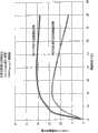
图2为一EC层合板的应力分布图,该EC装置包括层合在苏打石灰玻璃上的低热膨胀系数的玻璃;Figure 2 is a stress distribution diagram of an EC laminate comprising low coefficient of thermal expansion glass laminated to soda lime glass;
图3a为在太阳照射下的多个EC层合板中的多个EC层合板最大边缘张应力的对比图;Figure 3a is a comparison diagram of the maximum edge tensile stress of multiple EC laminates among multiple EC laminates under solar irradiation;
图3b为在太阳照射下的多个EC层合板中的一个EC层合板最大边缘张应力的对比图;Figure 3b is a comparison diagram of the maximum edge tensile stress of an EC laminate among multiple EC laminates under solar irradiation;
图4提供了以EC衬底、EC外层合玻璃板和隔层厚度为函数而进行的冲击测试的简略说明;Figure 4 provides a simplified illustration of the impact tests performed as a function of EC substrate, EC outer laminate glass pane, and interlayer thickness;
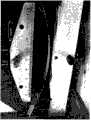
图5提供了四点弯曲测试的实施例,其中显示了在测试状态下的激光切割玻璃试样;Figure 5 provides an example of a four-point bend test, showing a laser cut glass specimen under test;
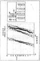
图6提供了用于比较机械切割和激光切割玻璃板的玻璃试样强度概率图。Figure 6 provides a probability plot of the strength of a glass specimen comparing mechanically cut and laser cut glass panels.
发明内容Contents of the invention
申请人研制了一种改进的IGU,该IGU包括EC装置层合板。申请人还研发了一种制造所述改进的EC装置层合板和IGU的方法。Applicants have developed an improved IGU comprising an EC device laminate. Applicants have also developed a method of making the improved EC device laminate and IGU.
在本发明的一个方面,申请人发现一种制造电致变色装置层合板的方法,该方法包括:(a)提供电致变色衬底;(b)将所述电致变色衬底切割成一个或多个衬底子板;(c)在每个所述衬底子板上制造复数个电致变色装置前躯体;(d)将所述复数个电致变色装置前躯体中的每一个切割成单独的电致变色装置;(e)将各个所述单独的电致变色装置层合在独立的外层合玻璃板上(这里将将一步描述该“先切割然后涂覆然后切割”方法的例子)。在一个实施例中,所述电致变色装置前驱体被激光切割。在另一实施例中,所述电致变色装置前驱体被电热切割。In one aspect of the present invention, applicants have discovered a method of manufacturing an electrochromic device laminate comprising: (a) providing an electrochromic substrate; (b) cutting said electrochromic substrate into a or a plurality of substrate sub-plates; (c) fabricate a plurality of electrochromic device precursors on each of said substrate sub-plates; (d) cut each of said plurality of electrochromic device precursors into individual (e) laminating each of said individual electrochromic devices on a separate outer laminated glass sheet (an example of this "cut then coat then cut" approach will be described in one step here) . In one embodiment, the electrochromic device precursor is laser cut. In another embodiment, the electrochromic device precursor is electrothermally cut.
在另一实施例中,所述单独的电致变色装置的边缘强度为至少约60MPa。在另一实施例中,所述单独的电致变色装置的边缘强度为至少约69MPa。在另一实施例中,所述单独的电致变色装置的边缘强度为至少约75MPa。在另一实施例中,所述单独的电致变色装置的边缘强度为至少约100MPa。In another embodiment, the individual electrochromic device has an edge strength of at least about 60 MPa. In another embodiment, the individual electrochromic device has an edge strength of at least about 69 MPa. In another embodiment, the individual electrochromic device has an edge strength of at least about 75 MPa. In another embodiment, the individual electrochromic device has an edge strength of at least about 100 MPa.
在另一实施例中,所述单独的电致变色装置的大小与所述外层合玻璃板的大小大致相同。在另一实施例中,所述单独的电致变色装置的至少一个尺寸比所述外层合玻璃板小。在另一实施例中,所述单独的电致变色装置相对于所述外层合玻璃板,至少一个尺寸上内缩约0.5mm-约3mm。在另一实施例中,所述单独的电致变色装置相对于所述外层合玻璃板,至少在一个尺寸上内缩约1.0mm-约2.0mm,优选地,所有尺寸均内缩约1.0mm-约2.0mm。In another embodiment, the separate electrochromic device is about the same size as the outer laminated glass pane. In another embodiment, said separate electrochromic device is smaller in at least one dimension than said outer laminated glass pane. In another embodiment, said separate electrochromic device is set back in at least one dimension from about 0.5 mm to about 3 mm relative to said outer laminated glass pane. In another embodiment, said separate electrochromic device is inset relative to said outer laminated glass pane in at least one dimension from about 1.0 mm to about 2.0 mm, preferably in all dimensions by about 1.0 mm mm - about 2.0mm.
在另一实施例中,所述电致变色衬底和所述外层合玻璃板采用相同的材料。在另一实施例中,所述电致变色衬底的材料与所述外层合玻璃板的材料不同。在另一实施例中,所述电致变色衬底的材料选自以下材料:低热膨胀系数玻璃、苏打石灰玻璃、铝硅酸盐玻璃、浮法硼硅玻璃(borofloat glass)、硼铝硅酸盐玻璃(boroaluminosilicate glass)、其它低钠成分玻璃(low-sodium composition glass)或者聚合物。在另一实施例中,所述电致变色衬底的热膨胀系数对于玻璃衬底而言,范围为约2.0ppm/k至约10.0ppm/k,而对于聚合物衬底材料,达到约80ppm/k。在另一实施例中,所述电致变色衬底的热膨胀系数的范围为约4ppm/k至约8ppm/k。在另一实施例中,所述电致变色衬底的厚度为约0.7mm至约6mm。In another embodiment, the electrochromic substrate and the outer laminated glass pane are of the same material. In another embodiment, said electrochromic substrate is of a different material than said outer laminated glass pane. In another embodiment, the material of the electrochromic substrate is selected from the following materials: glass with low thermal expansion coefficient, soda lime glass, aluminosilicate glass, borofloat glass, boroaluminosilicate Boroaluminosilicate glass, other low-sodium composition glass, or polymers. In another embodiment, the coefficient of thermal expansion of the electrochromic substrate ranges from about 2.0 ppm/k to about 10.0 ppm/k for glass substrates and reaches about 80 ppm/k for polymer substrate materials. k. In another embodiment, the coefficient of thermal expansion of the electrochromic substrate ranges from about 4 ppm/k to about 8 ppm/k. In another embodiment, the thickness of the electrochromic substrate is from about 0.7 mm to about 6 mm.
在另一实施例中,所述外层合玻璃板的材料可以从以下材料选择:低热膨胀系数玻璃、苏打石灰浮法玻璃、铝硅酸盐玻璃、浮法硼硅玻璃、硼铝硅酸盐玻璃、强化玻璃、钢化玻璃或聚合物。在另一实施例中,所述外层合玻璃板的热膨胀系数的范围为约2ppm/K至10ppm/K。对于聚合物基衬底,热膨胀系数可以达到约80ppm/K。在另一实施例中,所述外层合玻璃板的厚度为约2.3mm至约12mm。在另一实施例中,所述层间材料可以从以下材料选择:聚乙烯醇缩丁醛、离子化聚合物、乙基醋酸乙烯共聚物、聚氨酯或者它们的混合物。In another embodiment, the material of the outer laminated glass panels may be selected from the following materials: low coefficient of thermal expansion glass, soda lime float glass, aluminosilicate glass, borosilicate float glass, boroaluminosilicate Glass, strengthened glass, tempered glass or polymer. In another embodiment, the outer laminated glass pane has a coefficient of thermal expansion in the range of about 2 ppm/K to 10 ppm/K. For polymer-based substrates, the coefficient of thermal expansion can reach about 80 ppm/K. In another embodiment, the thickness of the outer laminated glass pane is from about 2.3 mm to about 12 mm. In another embodiment, the interlayer material may be selected from the following materials: polyvinyl butyral, ionomeric polymers, ethyl vinyl acetate copolymers, polyurethanes, or mixtures thereof.
另一方面,本发明提供了一种根据所述“先切割然后涂覆然后切割”方法制备的层合板。在另一实施例中,根据所述“先切割然后涂覆然后切割”方法制备的层合板的衬底的边缘强度为至少约60MPa。In another aspect, the present invention provides a laminate prepared according to said "cut then coat then cut" method. In another embodiment, the substrate of the laminate prepared according to the "cut then coat then cut" method has an edge strength of at least about 60 MPa.
在本发明的另一方面,申请人发现了一种制造电致变色装置层合板的方法,该方法包括:(a)提供电致变色衬底;(b)在所述电致变色衬底上制造复数个电致变色装置前驱体;(c)将所述复数个电致变色装置前躯体中的每一个切割成单独的电致变色装置;(d)将各个所述单独的电致变色装置层合在独立的外层合玻璃板上(这里将进一步描述该“先涂覆后切割”方法的例子)。所述EC装置前驱体可以通过机械切割、激光切割或者电热切割。In another aspect of the present invention, applicants have discovered a method of manufacturing an electrochromic device laminate comprising: (a) providing an electrochromic substrate; (b) forming an electrochromic substrate on said electrochromic substrate manufacturing a plurality of electrochromic device precursors; (c) cutting each of said plurality of electrochromic device precursors into individual electrochromic devices; (d) cutting each of said individual electrochromic devices Laminated to a separate outer laminated glass panel (an example of this "coat then cut" approach is described further herein). The EC device precursor can be cut by mechanical cutting, laser cutting or electrothermal cutting.
在另一实施例中,所述单独的电致变色装置的边缘强度为至少约60MPa。在另一实施例中,所述单独的电致变色装置的边缘强度为至少约69MPa。在另一实施例中,所述单独的电致变色装置的边缘强度为至少约75MPa。在另一实施例中,所述单独的电致变色装置的边缘强度为至少约100MPa。In another embodiment, the individual electrochromic device has an edge strength of at least about 60 MPa. In another embodiment, the individual electrochromic device has an edge strength of at least about 69 MPa. In another embodiment, the individual electrochromic device has an edge strength of at least about 75 MPa. In another embodiment, the individual electrochromic device has an edge strength of at least about 100 MPa.
在另一实施例中,所述单独的电致变色装置的大小与所述外层合玻璃板的大小大致相同。在另一实施例中,所述单独的电致变色装置的至少一个尺寸比所述外层合玻璃板小。在另一实施例中,所述单独的电致变色装置相对于所述外层合玻璃板,至少一个尺寸上内缩约0.5mm-约3mm。在另一实施例中,所述单独的电致变色装置相对于所述外层合玻璃板,至少在一个尺寸上内缩约1.0mm-约2.0mm。In another embodiment, the separate electrochromic device is about the same size as the outer laminated glass pane. In another embodiment, said separate electrochromic device is smaller in at least one dimension than said outer laminated glass pane. In another embodiment, said separate electrochromic device is set back in at least one dimension from about 0.5 mm to about 3 mm relative to said outer laminated glass pane. In another embodiment, said separate electrochromic device is set back in at least one dimension from about 1.0 mm to about 2.0 mm relative to said outer laminated glass pane.
在另一实施例中,所述退火玻璃衬底和所述外层合玻璃板采用相同的材料。在另一实施例中,所述电致变色衬底的材料与所述外层合玻璃板的材料不同。所述电致变色衬底的材料选自以下材料:低热膨胀系数玻璃、苏打石灰玻璃、铝硅酸盐玻璃、浮法硼硅玻璃、硼铝硅酸盐玻璃、低钠成分玻璃或者聚合物。在另一实施例中,所述电致变色衬底的热膨胀系数的范围为约2.0ppm/k至约10.0ppm/k。对于聚合物基衬底,热膨胀系数能达到约80ppm/k。在另一实施例中,所述电致变色衬底的热膨胀系数范围为约4ppm/k至约8ppm/k。在另一实施例中,所述电致变色衬底的厚度为约0.7mm至约6mm。In another embodiment, the annealed glass substrate and the outer laminated glass pane are of the same material. In another embodiment, said electrochromic substrate is of a different material than said outer laminated glass pane. The material of the electrochromic substrate is selected from the following materials: low thermal expansion coefficient glass, soda lime glass, aluminosilicate glass, float borosilicate glass, boroaluminosilicate glass, low sodium composition glass or polymer. In another embodiment, the coefficient of thermal expansion of the electrochromic substrate ranges from about 2.0 ppm/k to about 10.0 ppm/k. For polymer-based substrates, the coefficient of thermal expansion can reach about 80 ppm/K. In another embodiment, the electrochromic substrate has a coefficient of thermal expansion ranging from about 4 ppm/k to about 8 ppm/k. In another embodiment, the thickness of the electrochromic substrate is from about 0.7 mm to about 6 mm.
在另一实施例中,所述外层合玻璃板的材料可以从以下材料选择:低热膨胀系数玻璃、苏打石灰浮法玻璃、铝硅酸盐玻璃、浮法硼硅玻璃、硼铝硅酸盐玻璃、强化玻璃、钢化玻璃或聚合物。在另一实施例中,所述外层合玻璃板的热膨胀系数的范围为约2ppm/K至10ppm/K。在另一实施例中,所述外层合玻璃板的厚度为约2.3mm-约12mm。在另一实施例中,所述层间材料可以从以下材料选择:聚乙烯醇缩丁醛、离子化聚合物、乙基醋酸乙烯共聚物、聚氨酯或者它们的混合物。In another embodiment, the material of the outer laminated glass panels may be selected from the following materials: low coefficient of thermal expansion glass, soda lime float glass, aluminosilicate glass, borosilicate float glass, boroaluminosilicate Glass, strengthened glass, tempered glass or polymer. In another embodiment, the outer laminated glass pane has a coefficient of thermal expansion in the range of about 2 ppm/K to 10 ppm/K. In another embodiment, the thickness of the outer laminated glass pane is from about 2.3 mm to about 12 mm. In another embodiment, the interlayer material may be selected from the following materials: polyvinyl butyral, ionomeric polymers, ethyl vinyl acetate copolymers, polyurethanes, or mixtures thereof.
另一方面,本发明提供了一种根据所述“先涂覆后切割”方法制备的层合板。在另一实施例中,根据所述“先切割然后涂覆然后切割”方法制备的层合板的衬底的边缘强度为至少约60MPa。In another aspect, the present invention provides a laminate prepared according to the "coat then cut" method. In another embodiment, the substrate of the laminate prepared according to the "cut then coat then cut" method has an edge strength of at least about 60 MPa.
在本发明的另一方面,申请人发现了一种层合板,所述层合板包括:(a)电致变色装置,所述电致变色装置包括退火玻璃衬底上的电致变色叠层;(b)外层合玻璃板;以及(c)夹设在所述电致变色装置和所述外层合玻璃板之间的层间材料。在一些实施例中,所述电致变色装置的边缘强度为至少约60MPa。在另一实施例中,所述电致变色装置的边缘强度为至少约69MPa。在另一实施例中,所述电致变色装置的边缘强度为至少约75MPa。在另一实施例中,所述电致变色装置的边缘强度为至少约100MPa。在另一实施例中,所述电致变色装置由激光切割制备。在另一实施例中,所述电致变色装置由电热切割制备。在另一实施例中,所述层合板是集成玻璃单元的部分。In another aspect of the present invention, applicants have discovered a laminate comprising: (a) an electrochromic device comprising an electrochromic stack on an annealed glass substrate; (b) an outer laminated glass pane; and (c) an interlayer material interposed between said electrochromic device and said outer laminated glass pane. In some embodiments, the electrochromic device has an edge strength of at least about 60 MPa. In another embodiment, the electrochromic device has an edge strength of at least about 69 MPa. In another embodiment, the electrochromic device has an edge strength of at least about 75 MPa. In another embodiment, the electrochromic device has an edge strength of at least about 100 MPa. In another embodiment, the electrochromic device is fabricated by laser cutting. In another embodiment, the electrochromic device is fabricated by electrothermal cutting. In another embodiment, the laminate is part of an integrated glazing unit.
在另一实施例中,所述退火玻璃衬底和所述外层合玻璃板采用相同的材料。在另一实施例中,所述退火玻璃衬底的材料与所述外层合玻璃板的材料不同。所述退火玻璃衬底的材料选自以下材料:低热膨胀系数玻璃、苏打石灰玻璃、铝硅酸盐玻璃、浮法硼硅玻璃、硼铝硅酸盐玻璃、低钠成分玻璃或者聚合物。在另一实施例中,所述退火玻璃衬底的热膨胀系数的范围为约2.0ppm/k至约10.0ppm/k。对于聚合物基衬底,热膨胀系数能达到约80ppm/k。在另一实施例中,所述电致变色衬底的热膨胀系数范围为约4ppm/k至约8ppm/k。在另一实施例中,所述退火玻璃衬底的厚度为约0.7mm至约6mm。在另一实施例中,所述退火玻璃板的厚度与所述外层合玻璃板的厚度相同。在另一实施例中,所述退火玻璃板和所述外层合玻璃板的厚度不同。In another embodiment, the annealed glass substrate and the outer laminated glass pane are of the same material. In another embodiment, said annealed glass substrate is of a different material than said outer laminated glass pane. The material of the annealed glass substrate is selected from the following materials: low thermal expansion coefficient glass, soda lime glass, aluminosilicate glass, float borosilicate glass, boroaluminosilicate glass, low sodium composition glass or polymer. In another embodiment, the thermal expansion coefficient of the annealed glass substrate ranges from about 2.0 ppm/k to about 10.0 ppm/k. For polymer-based substrates, the coefficient of thermal expansion can reach about 80 ppm/K. In another embodiment, the electrochromic substrate has a coefficient of thermal expansion ranging from about 4 ppm/k to about 8 ppm/k. In another embodiment, the annealed glass substrate has a thickness of about 0.7 mm to about 6 mm. In another embodiment, the thickness of the annealed glass sheet is the same as the thickness of the outer laminated glass sheet. In another embodiment, the annealed glass pane and the outer laminated glass pane are of different thicknesses.
在另一实施例中,所述外层合玻璃板的材料可以从以下材料选择:低热膨胀系数玻璃、苏打石灰浮法玻璃、铝硅酸盐玻璃、浮法硼硅玻璃、硼铝硅酸盐玻璃、强化玻璃、钢化玻璃或聚合物。在另一实施例中,所述外层合玻璃板的热膨胀系数的范围为约2ppm/K至10ppm/K。在另一实施例中,对于聚合物基衬底,热膨胀系数可以达到约80ppm/K。在另一实施例中,所述外层合玻璃板的厚度为约2.3mm-约12mm。In another embodiment, the material of the outer laminated glass panels may be selected from the following materials: low coefficient of thermal expansion glass, soda lime float glass, aluminosilicate glass, borosilicate float glass, boroaluminosilicate Glass, strengthened glass, tempered glass or polymer. In another embodiment, the outer laminated glass pane has a coefficient of thermal expansion in the range of about 2 ppm/K to 10 ppm/K. In another embodiment, the coefficient of thermal expansion can be up to about 80 ppm/K for a polymer based substrate. In another embodiment, the thickness of the outer laminated glass pane is from about 2.3 mm to about 12 mm.
在另一实施例中,所述退火玻璃衬底的大小与所述外层合玻璃板的大小大致相同。在另一实施例中,所述退火玻璃衬底的至少一个尺寸比所述外层合玻璃板小。在另一实施例中,所述退火玻璃衬底相对于所述外层合玻璃板,至少一个尺寸上内缩约0.5mm-约3mm。在另一实施例中,所述退火玻璃衬底相对于所述外层合玻璃板,至少在一个尺寸上内缩约1.0mm-约2.0mm。在另一实施例中,较小的所述退火玻璃衬底的周边的至少一侧被层间材料或其它材料围绕,比如聚合物,该聚合物包括硅酮、聚氨酯、环氧树脂和丙烯酸酯。In another embodiment, the annealed glass substrate is about the same size as the outer laminated glass pane. In another embodiment, said annealed glass substrate is smaller in at least one dimension than said outer laminated glass pane. In another embodiment, the annealed glass substrate indents in at least one dimension from about 0.5 mm to about 3 mm relative to the outer laminated glass pane. In another embodiment, the annealed glass substrate indents in at least one dimension from about 1.0 mm to about 2.0 mm relative to the outer laminated glass pane. In another embodiment, at least one side of the perimeter of the smaller said annealed glass substrate is surrounded by an interlayer material or other material, such as a polymer including silicone, polyurethane, epoxy and acrylate .
在另一实施例中,所述层间材料可以从以下材料选择:聚乙烯醇缩丁醛、离子化聚合物、乙基醋酸乙烯共聚物、聚氨酯或者它们的混合物。In another embodiment, the interlayer material may be selected from the following materials: polyvinyl butyral, ionomeric polymers, ethyl vinyl acetate copolymers, polyurethanes, or mixtures thereof.
在另一实施例中,所述退火玻璃衬底为热膨胀系数为8.5ppm/k的苏打石灰浮法玻璃,所述外层合玻璃板为热膨胀系数为8.5ppm/k的钢化苏打石灰浮法玻璃,所述层间材料为聚乙烯醇缩丁醛。在另一实施例中,所述层间材料为SentryGlas
在本发明的另一方面,申请人发现了一种层合板,该层合板包括:(a)电致变色装置,所述电致变色装置包括衬底上的电致变色叠层;(b)外层合玻璃板;以及(c)夹设在所述电致变色装置和所述外层合玻璃板之间的层间材料。在另一实施例中,所述电致变色装置由激光切割或电热切割制备。In another aspect of the present invention, applicants have discovered a laminate comprising: (a) an electrochromic device comprising an electrochromic stack on a substrate; (b) an outer laminated glass pane; and (c) an interlayer material interposed between said electrochromic device and said outer laminated glass pane. In another embodiment, the electrochromic device is fabricated by laser cutting or electrothermal cutting.
申请人意外地发现,本发明的所述电致变色装置层合板(或者包括该层合板的IGU)能够承受的应力,与在钢化或强化玻璃衬底上制造的传统的电致变色装置(或者包括这种传统的电致变色装置的IGU)遇到的应力相当。这样,本发明的所述EC装置层合板能够承受相似的玻璃中心和边缘应力,且能够承受至少17MPa的应力。Applicants have unexpectedly discovered that the electrochromic device laminates of the present invention (or IGUs comprising such laminates) can withstand stresses comparable to conventional electrochromic devices (or IGUs comprising such laminates) fabricated on tempered or strengthened glass substrates. IGUs comprising such conventional electrochromic devices experience comparable stress. Thus, the EC device laminates of the present invention are capable of withstanding similar glass center and edge stresses, and capable of withstanding stresses of at least 17 MPa.
在一些实施例中,承受相似的应力意味着本发明的电致变色装置层合板或者IGUs通过了与传统的电致变色装置或IGUs相同的工业标准测试。在另一些实施例中,承受相似的应力意味着本发明的电致变色装置层合板或者IGUs能够安全地承受(i)大于在传统的EC应用中遇到的最大使用中热机械应力的应力,和/或(ii)与传统电致变色装置或IGUs相同的工作荷载或者应力的至少约50%。申请人还惊喜地发现,这些目标可以通过在退火玻璃衬底上涂覆或沉积所述电致变色叠层来实现。In some embodiments, being subjected to similar stress means that the electrochromic device laminates or IGUs of the present invention pass the same industry standard tests as conventional electrochromic devices or IGUs. In other embodiments, withstanding similar stress means that the electrochromic device laminates or IGUs of the present invention can safely withstand (i) stresses greater than the maximum in-use thermomechanical stress encountered in conventional EC applications, and/or (ii) at least about 50% of the same working load or stress as conventional electrochromic devices or IGUs. Applicants have also surprisingly found that these objectives can be achieved by coating or depositing said electrochromic stack on an annealed glass substrate.
申请人意外地发现,该改进的制造方法使得电致变色装置层合板或IGUs能够承受的工作荷载或应力与传统方法生产的IGU遇到的工作荷载或应力相当,同时提高了制造效率且满足工业标准。Applicants have unexpectedly discovered that this improved manufacturing method enables electrochromic device laminates or IGUs to withstand operating loads or stresses comparable to those encountered with conventionally produced IGUs, while increasing manufacturing efficiency and meeting industry requirements. standard.
此外,申请人意外地发现,激光切割退火玻璃衬底可以产生足够的无缺陷边缘,可以认为,该边缘将能够忍受所述EC装置层压板在使用寿命中会受到的全部热和荷载应力。申请人通过在热和机械应力参数空间的高端,测试了激光切割的玻璃和图1b所示的EC装置层合板,确定出激光切割的EC装置层合板或者衬底是高度耐用的,并适合在住宅和商业建筑应用和其它应用中使用。In addition, applicants have unexpectedly discovered that laser cutting annealed glass substrates can produce sufficiently defect-free edges that it is believed that the edges will be able to withstand the full range of thermal and load stresses to which the EC device laminate will be exposed during its useful life. Applicants have determined that laser-cut EC device laminates or substrates are highly durable and suitable for use in Used in residential and commercial building applications and other applications.
此外,申请人发现,这里描述的所述“先涂覆后切割”和所述“先切割然后涂覆然后切割”两种方法都允许在大衬底板上涂覆和在涂覆后变为自定义尺寸。申请人还发现,该方法提供了提高的加工控制和所述EC装置的薄膜涂层的整体均匀性。事实上,可以认为,当使用的所有玻璃板具有大致相同的尺寸时,对于各玻璃板的后续加工温度和溅射等离子条件也将大致相同。可以认为,这将导致更有效的连续涂覆或溅射操作,而不需要放慢或停止生产或者为多种玻璃厚度、颜色和大小进行工艺调整。因此,在制造电致变色装置或者IGU时,生产率和运行时间最大化,进而降低生产成本。Furthermore, applicants have found that both the "coat then cut" and the "cut then coat then cut" methods described herein allow for coating on large substrates and becoming self-sustaining after coating. Define dimensions. Applicants have also found that this method provides improved process control and overall uniformity of the thin film coating of the EC device. In fact, it is believed that when all the glass sheets used are of approximately the same size, the subsequent processing temperature and sputtering plasma conditions will also be approximately the same for each glass sheet. It is believed that this will lead to more efficient continuous coating or sputtering operations without the need to slow down or stop production or make process adjustments for multiple glass thicknesses, colors and sizes. Thus, when manufacturing electrochromic devices or IGUs, productivity and run time are maximized, thereby reducing production costs.
具体实施方式Detailed ways
EC装置层合板EC device laminate
一方面,本发明提供了一种EC装置层合板,其包括电致变色装置、EC外层合玻璃板、和夹设在所述电致变色装置和所述外层合玻璃板之间的层间材料,所述电致变色装置包括EC衬底上的电致变色叠层。In one aspect, the present invention provides an EC device laminate comprising an electrochromic device, an EC outer laminated glass pane, and a layer interposed between the electrochromic device and the outer laminated glass pane intermediate material, the electrochromic device comprises an electrochromic stack on an EC substrate.
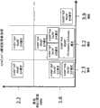
所述EC装置层合板29和包括该EC装置层合板29的IGU30展示在图1B中。EC装置层合板29由叠在EC外层合玻璃板22上的EC装置32组成。在所述EC装置32和所述EC外层合玻璃板32之间设有层间材料28,该层间材料28粘接所述EC装置32和所述外层合玻璃板22。所述EC装置32自身由沉积在EC衬底31上的EC叠层21构成。完整的IGU30包括所述与另一玻璃板20结合在一起的EC装置层合板29,所述EC装置层合板29和玻璃板20由间隔部件27隔开。图1B显示了两块玻璃板的IGU,然而,本发明还考虑了具有三块或更多玻璃板的IGU(附加的玻璃板可以是任意形状或尺寸的,且可以包括本领域已知的任何涂层,有色或无色)。The
本领域技术人员熟知的任何EC叠层21均可以使用。例如,专利号为5321544、5404244、7372610和7593154的美国专利中描述的一些示例性的EC叠层,这些专利公开的内容通过引用在这里整体引入本申请。Any
在一个实施例中,至少所述EC装置层合板29的EC衬底31由退火玻璃构成。这里使用的“退火玻璃”表示这样一种玻璃,该玻璃经热处理和后续的迅速冷却而不产生内部应力。这种玻璃包括典型地被划分为退火玻璃或浮法玻璃的玻璃,而不包括强化玻璃或钢化玻璃。In one embodiment, at least the
在其它的实施例中,EC衬底31和EC外层合玻璃板22均由退火玻璃构成。在EC衬底31和EC外层合玻璃板22都由退火玻璃构成的实施例中,使用的退火玻璃可以相同(匹配)或不同(不匹配)。使用的所述退火玻璃衬底还可以具有相同或不同的热膨胀系数、或者不同类型和/或数量的掺杂物。In other embodiments, both the
例如,在一个“不匹配”的实施例中,衬底31可以由苏打石灰浮法玻璃构成,而EC外层合玻璃板22由低热膨胀系数的玻璃(低CTE(coefficient of thermal expansion)玻璃),或者反过来也一样。在一个“匹配”的实施例中,仅作为举例,衬底31和EC外层合玻璃板22可以都由苏打石灰浮法玻璃构成,或者可选地,两者都由低CET玻璃构成。For example, in a "mismatched" embodiment, the
除了上述限定的情况,“不匹配”还表示使用不同厚度的玻璃,不管玻璃的类型是相同的还是不同的。例如,衬底31和外层合玻璃板22可以由相同的材料制成,但是具有不同的厚度。或者,仅作为举例,衬底31可以由与外层合玻璃板22不同的材料制成,且它们具有不同的厚度。另外,仅作为举例,衬底31可以由与外层合玻璃板22相同类型的材料制成,但是具有不同的热膨胀系数和/或不同的厚度。In addition to the cases defined above, "mismatched" also means the use of different thicknesses of glass, regardless of whether the glass types are the same or different. For example,
本发明的所述EC衬底31可以从传统玻璃材料中选择,传统玻璃材料包括比如产自格尔德殿工业公司(Guardian Industries)(密歇根州奥本山的Guardian全球总部(GuardianGlobal Headquarters,Auburn Hills,MI))、皮尔金顿北美公司(Pilkington,North America)(俄亥俄州托莱多(Toledo,OH))、Cardinal Glass Industries公司(明尼苏达州伊登普雷里(Eden Prairie,MN))和AGC公司(乔治亚州阿尔法利塔旭硝子平板玻璃(AGC FlatGlass,Alpharetta,GI))的苏打石灰退火玻璃,这些公司生产大面积的薄玻璃。The
所述EC衬底31还可以选自以下材料:低CTE的浮法硼硅玻璃(borofloat glass)(比如可以从Schott公司(纽约州艾尔姆斯福特的肖特北美公司(Schott North America Elsford,NY))获得)、或者硼铝硅酸盐玻璃(boroaluminosilicate glass)(比如Corning的1737和Corning EAGLE XG,这两种玻璃都可以从纽约州科宁的康宁公司(CorningIncorporated,Corning,NY)获得)。此外,所述EC衬底31还可以选自铝硅酸盐玻璃。本领域技术人员能够选择适于此目的且符合本发明的限制的其他玻璃衬底。The
EC衬底31还可以由聚合物、共聚物、或者一种或多种聚合物或共聚物的混合物组成。聚合物包括但不限于聚酰亚胺、聚乙烯、聚萘二甲酸乙二醇酯(napthalate,PEM)、聚对苯二甲酸乙二酯(PET)、芳族聚酰胺(aramid)或者其它类似的聚合材料。本领域技术人员能够选择适于此目的且符合本发明的限制的其他聚合物衬底。
通常,所述EC衬底31可以具有任意厚度,取决于期望的应用(即居住建筑窗、商业建筑窗或者甚至汽车车窗)和期望的热/结构性能。典型地,衬底31的厚度为约0.7mm-约6mm。在一些实施例中,EC衬底31的厚度为约1.5mm-约2.3mm。In general, the
在一些实施例中,采用的退火玻璃或苏打石灰浮法玻璃的热膨胀系数为约7.0ppm/k-约10.0ppm/k。在另一些实施例中,采用的所述苏打石灰浮法玻璃的热膨胀系数为约8.2ppm/k-约9.0ppm/k。在一些采用低CTE玻璃的实施例中,热膨胀系数的范围为约2.0ppm/k-约6.4ppm/k。在一些使用低CTE玻璃的特殊的实施例中,热膨胀系数如下:Corning 1737(约3.76ppm/K)、Corning Eagle XGTM(约3.2ppm/K)和Schott Borofloat 33TM(约3.3ppm/K)。In some embodiments, the annealed glass or soda lime float glass employed has a coefficient of thermal expansion ranging from about 7.0 ppm/k to about 10.0 ppm/k. In other embodiments, the soda lime float glass employed has a coefficient of thermal expansion ranging from about 8.2 ppm/k to about 9.0 ppm/k. In some embodiments utilizing low CTE glass, the coefficient of thermal expansion ranges from about 2.0 ppm/k to about 6.4 ppm/k. In some specific embodiments using low CTE glasses, the coefficients of thermal expansion are as follows: Corning 1737 (about 3.76 ppm/K), Corning Eagle XG™ (about 3.2 ppm/K) and Schott Borofloat 33™ (about 3.3 ppm/K) .
本发明的所述EC外层合玻璃板22可以选自以下材料,包括强化玻璃、钢化玻璃、部分热强化或钢化玻璃、或者退火玻璃。和本领域已知的那些词语一样,“强化玻璃”和“钢化玻璃”都是这种类型的玻璃,该类玻璃被热处理以引起表面压缩和在其它方面强化玻璃。热处理的玻璃被分为完全钢化玻璃或者强化玻璃。根据Federal SpecificationDD-G-1403B(联邦标准DD-G-1403B),对于67Mpa或以上的边缘压缩来说,完全钢化玻璃必须具有约69Mpa或以上的表面压缩。可以认为,热强化玻璃必须具有约24-约69Mpa的表面压缩,或者约38-约67Mpa的边缘压。还可以认为,热强化玻璃的破碎特性彼此不同,在应力为约41-69Mpa时可能发生破碎。The EC outer
通常,所述EC外层合玻璃板22可以具有任意厚度,该厚度取决于希望的应用(即居住建筑窗、商业建筑窗或者甚至汽车车窗)和期望的热/结构性能。在一些实施例中,所述EC外层合玻璃板22可以由塑料构成,包括聚碳酸脂塑料。典型地,所述EC外层合玻璃板22的厚度为约2.3mm-约12mm。在一些实施例中,EC外层合玻璃板22的厚度为约2.3mm-约6mm。当然,如果实际应用需要,也可以采用较厚的玻璃,比如在承受大风负荷的建筑应用或者防弹或防爆应用中使用。In general, the EC outer
在一些实施例中,采用的退火玻璃或苏打石灰浮法玻璃的热膨胀系数为约7.0ppm/k-约10.0ppm/k。在另一些实施例中,采用的所述苏打石灰浮法玻璃的热膨胀系数为约8.2ppm/k-约9.0ppm/k。在一些采用低CTE玻璃的实施例中,热膨胀系数的范围为约2.0ppm/k-约6.4ppm/k。在一些使用低CTE玻璃的特殊的实施例中,热膨胀系数如下:Corning 1737(约3.76ppm/K)、Corning Eagle XGTM(约3.2ppm/K)和Schott Borofloat 33TM(约3.3ppm/K)。In some embodiments, the annealed glass or soda lime float glass employed has a coefficient of thermal expansion ranging from about 7.0 ppm/k to about 10.0 ppm/k. In other embodiments, the soda lime float glass employed has a coefficient of thermal expansion ranging from about 8.2 ppm/k to about 9.0 ppm/k. In some embodiments utilizing low CTE glass, the coefficient of thermal expansion ranges from about 2.0 ppm/k to about 6.4 ppm/k. In some specific embodiments using low CTE glasses, the coefficients of thermal expansion are as follows: Corning 1737 (about 3.76 ppm/K), Corning Eagle XG™ (about 3.2 ppm/K) and Schott Borofloat 33™ (about 3.3 ppm/K) .
在一些实施例中,EC衬底31和EC外层合玻璃板22具有不同的热膨胀系数。在另一些实施例中,EC衬底31和EC外层合玻璃板22的热膨胀系数相差小于约50%。在又一些实施例中,EC衬底31和EC外层合玻璃板22的热膨胀系数相差小于约30%。在另一些实施例中,EC衬底31和EC外层合玻璃板22的热膨胀系数相差小于约20%。在另一些实施例中,EC衬底31和EC外层合玻璃板22的热膨胀系数相差小于约10%。如这里所述,合适的层间材料28的选择有助于减小CTE不匹配引起的应力。In some embodiments,
例如,图2显示了低CTE玻璃用作EC衬底31、苏打石灰玻璃用作EC外层合玻璃板22、聚乙烯醇缩丁醛(polyvinylbutyral)用作层间材料28时,层合板的应力分布。该仿真显示了绕玻璃板的边缘的25mm宽的框架的遮蔽效果。可以认为,所述框架引起了所述层合板边缘和中心的温度梯度,进而导致边缘应力的形成。在层合结构的例子中,因为太阳吸收使得装置变热,CTE的不匹配引起了附加应力。这种CTE不匹配的效果如图3a所示,其中,吸收太阳的低CTE/苏打石灰玻璃层合板在受到1000W/m2的入射辐射时,与相同的日照条件下的苏打石灰/苏打石灰层合结构相比,具有更高的峰值应力水平,同样如图3a所示。如这些例子所显示的,随着EC层合板吸收更多的太阳辐射,最大边缘应力随时间变化,在接近40分钟后,达到约20.5MPa的最大应力。在更长的时间后,通过玻璃从暴露区域到被遮蔽的边缘区域的热传导将导致温度平衡,并使得相应的热应力从它们的峰值水平减小。可以认为,在与图3a中相同的边缘框架遮蔽和太阳吸收条件下,当两种低CTE玻璃板层合在一起时,可以减小这种应力,如图3b所示。For example, Figure 2 shows the stress of the laminate when low CTE glass is used as the
在优选的实施例中,EC衬底31的边缘被保护不受到装运和机械损伤。在不想被任何特别理论绑住的情况下,可以认为,如果EC衬底31的边缘明显裂开或破裂,EC装置的整体强度将降低。在本发明的一些实施例中,EC衬底31相对于EC外层合玻璃板22内缩。在另一些实施例中,EC衬底31至少有一个尺寸,优选地至少有两个尺寸,更优选地所有尺寸的大小略小于EC外层合玻璃板22的大小。在一些实施例中,EC衬底31相对于玻璃板22,在至少一个尺寸上内缩约0.5mm-约3mm,优选地,沿着周边内缩约0.5mm-约3mm。在另一些实施例中,EC衬底31相对于玻璃板22,在至少一个尺寸上内缩约1.0mm-约2.0mm,优选地,沿着周边内缩约1.0mm-约2.0mm。In a preferred embodiment, the edges of the
在一些实施例中,内缩的深度由层合接合/制造过程中两块玻璃的自动位置公差、以及热层合过程中发生的微小位移决定。在一些实施例中,层间材料在热处理过程中可以绕EC衬底31的边缘流动,提供了保护元件,可以相信,这可以进一步保护EC装置层合板29在装运和安装过程中不被损伤。在一些实施例中,添加过多的层间材料来实现这一目的。在另一些实施例中,另外的保护材料可以沉积在所述EC装置的周边,比如聚合物(包括但不限于环氧树脂、聚氨酯、硅酮和丙烯酸酯)。这些材料的用量可以不同以达到期望的结果。In some embodiments, the depth of the setback is determined by automatic positional tolerances of the two glasses during lamination bonding/fabrication, as well as minor displacements that occur during thermal lamination. In some embodiments, interlayer material may flow around the edges of
所述层间材料可以选择能使EC装置32通过本领域的已知方法层合到EC外层合玻璃板22上的任何材料。通常,层间材料28应当具有以下特征的结合:(a)高透光性;(b)低雾度(low haze);(c)高抗冲击性;(d)高穿透阻力;(e)抗紫外线;(f)良好的长期热稳定性;(g)对玻璃和/或其它聚合材料/薄板具有充足的粘着力;(h)低吸湿性;(i)高防潮性;(j)优异的耐候性;和(k)应力荷载的高抗性(比如冲击荷载或者风荷载)。在一些实施例中,层间材料28至少为EC装置32和EC外层合玻璃板22提供了足够的粘着力,以防止其在使用中应力荷载的情况下分层,并且被选择为使得EC装置层合板29的视觉特征不会受到负面影响。在另一些实施例中,层间材料可以这样选择,以使其在两种荷载模式(可以参见例如ANSI Z97.1中的冲击测试和ASTM E1300的风荷载标准)下都能满足工业标准性能指标。The interlayer material can be selected to be any material that enables the
在一个实施例中,合适的层间材料28为聚乙烯醇缩丁醛(PVB),可以购买Solutia Inc.(密苏里州圣路易(St.Louis,Missouri))的商品名为SaflexTM的产品。PVB还可以购买DuPont公司(特拉华州威尔明顿(Wilmington,DE))的商品名为ButaciteTM的产品。作为层间材料28的其它合适的材料包括离子化材料(ionomeric materials)(比如DuPont的SentryGlas PlusTM(SGP))、乙基醋酸乙烯共聚物(EVA)和交联聚氨酯(cross-linkingpolyurethanes)(比如现场浇注树脂)或者热塑性聚氨酯。当然,还可以使用上述材料的任意组合。另外,其它聚合材料也可以用作层间材料28,只要它们满足前述热机械的、粘着力和透光的功能要求中的至少部分。这还包括由复合的聚合物层构成的层间材料,复合的聚合物层被设计来改进消声、防弹和抗爆用途。本领域技术人员很容易获得这些材料。In one embodiment, a
在另一些实施例中,层间材料28可以包括硅酮和环氧树脂。In other embodiments,
如果所述EC衬底31和EC外层合玻璃板22由相同的材料构成,那么可以认为,两块玻璃板具有大致相同的热膨胀系数。当材料不同时,即比如图2所示的不匹配情况,在不想被任何特定理论绑住的情况下,可以认为合适的层间材料28的选择可以影响所述不匹配的玻璃板之间应力的传递和分布,进而可以认为,可以消除所述层合板中不同点的至少部分应力。If the
对于玻璃板之间的CTE不匹配的层合结构,人们认为隔层应当这样选择:(1)足够柔软,不会将张应力从CTE较大的玻璃板传递到CTE较小的玻璃板;或者(2)由于层压温度而具有足够的硬度,以使得在冷却过程中压应力从CTE较大的玻璃板向CTE较小的玻璃板传递,其中在低温时具有可以忽略不计的聚合物力学松弛。For laminates with mismatched CTEs between the glass sheets, it is believed that the interlayer should be selected so that (1) it is soft enough not to transfer tensile stress from the glass sheet with the higher CTE to the glass sheet with the lower CTE; or (2) Sufficient stiffness due to the lamination temperature such that compressive stress is transferred from the larger CTE glass sheet to the smaller CTE glass sheet during cooling with negligible mechanical relaxation of the polymer at low temperatures .
图3a-3b提供了一层合板的边缘抗张强度的峰值的对比(其中的玻璃板的厚度分别为0.7mm和6mm),该层合板暴露在太阳辐射下且边缘被1”窗/建筑框遮蔽。匹配(低CTE/低CTE;苏打石灰/苏打石灰)和不匹配的(低CTE/苏打石灰)例子均显示为时间的函数。对于硬的层间材料(应力传递)而言,低CTE/苏打石灰组合的有效应力可以大于苏打石灰/苏打石灰组合。这样,人们认为,产生的边缘应力可以由层间材料的热机械性能决定。Figures 3a-3b provide a comparison of the peak tensile strength at the edge of a laminate (thicknesses of 0.7mm and 6mm glass sheets, respectively) exposed to solar radiation and edged by a 1" window/building frame Shading. Both matched (low CTE/low CTE; soda lime/soda lime) and mismatched (low CTE/soda lime) examples are shown as a function of time. For hard interlayer materials (stress transfer), low CTE The effective stress of the /soda lime combination can be greater than that of the soda lime/soda lime combination. Thus, it is believed that the resulting edge stress can be determined by the thermomechanical properties of the interlayer material.
EC装置层合板29(或者包括这些层合板的IGUs30)被认为可以承受与制造在淬火或热处理玻璃衬底上的传统电致变色装置(或者包括这种传统的电致变色装置的IGUs)相当的应力。EC device laminates 29 (or
在一些实施例中,承受相当的应力意味着本发明的EC装置层合板29或者IGUs30通过了和传统的电致变色装置或IGUs相同的工业标准测试。在另一些实施例中,承受相当的应力意味着本发明的EC装置层合板29或者IGUs30能够安全地承受(i)大于在传统的EC应用中遇到的最大使用中热机械应力的应力,和/或(ii)与传统电致变色装置或IGUs相同的工作荷载或者应力的至少约50%。在一些实施例中,所述EC装置层合板29能够承受至少约17MPa的热边缘应力(或工作荷载)。在另一些实施例中,所述EC装置层合板能够承受至少约21MPa的热边缘应力。在一些实施例中,所述EC装置层合板29的边缘强度为至少约60MPa。在另一些实施例中,所述EC装置或EC衬底的边缘强度为至少约69MPa。在另一些实施例中,所述EC装置或EC衬底的边缘强度为至少约75MPa。在另一些实施例中,所述EC装置或EC衬底的边缘强度为至少约100MPa。In some embodiments, being subjected to comparable stress means that the EC device laminates 29 or
在一些实施例中,所述EC层合板29或者EC衬底31是IGU的部分。用来形成所述IGU的所述玻璃板20可以选用任何材料,包括传统地在IGU结构中使用的玻璃或塑料。例如,可以使用任意类型的玻璃(苏打石灰玻璃、低CTE玻璃、钢化玻璃和/或退火玻璃)或者塑料。此外,所述玻璃板20自身可以是一种或多种材料的多层层合板(多层玻璃板、多层塑料片、以任意顺序交替的玻璃板和塑料片)。所述玻璃板20也可以染有任意颜色或者以任何传统的方式(比如化学或物理气相沉积涂层)在其一侧或两侧涂层。所述玻璃板20可以是电致变色或热变色装置。所述玻璃板20可以通过激光切割或者机械划线而成。此外,图1b中的IGU30可以是三层玻璃IGU,即这样一种IGU,该IGU包含一附加的玻璃(或者聚合物,比如丙烯酸)板20,该玻璃板20与玻璃板20或者EC装置层合板29中的一个相邻,但是通过间隔部件隔开。玻璃板20可以具有任意厚度或者任意特性,只要它满足最小商业或住宅建筑规范和/或窗口标准。In some embodiments, the
制造方法Manufacturing method
“先涂覆后切割”"Cut first, then cut"
在本发明的一个实施例中,申请人发现了一种制造方法,该方法涉及“先涂覆后切割”的概念。一方面,本发明提供了一种制造电致变色装置层合板的方法,该方法包括:提供电致变色衬底;在所述衬底上制造多个电致变色装置前躯体(precursors);将各个所述电致变色装置前躯体切割为单独的电致变色装置,以及将各个所述单独的电致变色装置层合到独立的外层合玻璃板上。在这里使用的“电致变色装置前躯体”为在将所述衬底切割为独立的EC装置之前,涂覆或沉积在衬底上的电致变色装置,典型地为上述薄膜的叠层。这样,多个EC装置前躯体在单个的衬底上或者如这里所描述的衬底子板(substrate daughter pane)上被制造出来。典型地,所述EC前躯体的轮廓被设计来在所述前躯体之间包含充足的空间,一般而言,以使得切割优选地不损伤任何薄膜或叠层。In one embodiment of the present invention, applicants have discovered a method of manufacture that involves the concept of "coat first, then cut". In one aspect, the present invention provides a method of manufacturing an electrochromic device laminate, the method comprising: providing an electrochromic substrate; fabricating a plurality of electrochromic device precursors on the substrate; Each of the electrochromic device precursors is diced into individual electrochromic devices, and each of the individual electrochromic devices is laminated to a separate outer laminated glass sheet. As used herein, an "electrochromic device precursor" is an electrochromic device, typically a stack of the aforementioned thin films, coated or deposited on a substrate prior to dicing the substrate into individual EC devices. In this way, multiple EC device precursors are fabricated on a single substrate or substrate daughter pane as described herein. Typically, the contours of the EC precursors are designed to contain sufficient space between the precursors, in general, such that cutting preferably does not damage any membranes or laminates.
在一些实施例中,所述EC装置(或者前躯体)32一般通过将所述EC叠层21涂在大的衬底板31(比如退火玻璃)上制成。所述叠层可以根据本领域中已知的方法涂覆或沉积,在此将这些方法引入本文。接着,所述EC装置(或者前驱体)32随后被切割(通过传统的机械设备、通过激光切割、或者电热切割方法,在此将详细描述)成期望的尺寸,该尺寸由最终的用途决定。当然,所述板也可以被切割为任意大小或形状。所述衬底也可以从一块大的板预先切割。然后,所述装置32被层合到EC外层合玻璃板22上,优选地用以提供附加的机械强度。所述EC装置层合板29可以包括如图1b所示的所述EC装置衬底32(也就是说,EC叠层21在所述EC层合板29的外侧),或者可选地,所述EC装置层合板29可以调整EC装置衬底32,使EC叠层21与所述层间材料28相接触(也就是说,所述EC叠层在所述层合板的内侧)。In some embodiments, the EC device (or precursor) 32 is generally fabricated by coating the
一旦所述EC装置层合板29被加工出来,它就可以与玻璃20结合,形成IGU30。Once the
在一些实施例中,所述EC外层合玻璃板与所述EC装置的大小大致相同。在另一些实施例中,所述EC外层合玻璃板与所述EC装置的大小不同。在一些实施例中,如前所述,所述EC衬底相对于所述外玻璃板内缩。在此进一步说明的是,所述EC外层合玻璃板可以与所述EC装置(或者沉积有所述EC装置的所述衬底)具有大致相同或不同的厚度、和/或热膨胀系数。所述外层合玻璃板可以机械切割或者激光切割。另一方面,本发明提供了根据该方法制成的层合板。In some embodiments, the EC outer laminated glass pane is about the same size as the EC device. In other embodiments, the EC outer laminated glass pane is a different size than the EC device. In some embodiments, the EC substrate is retracted relative to the outer glass sheet, as previously described. As further noted herein, the EC outer laminate glass pane may have approximately the same or a different thickness, and/or thermal expansion coefficient as the EC device (or the substrate on which the EC device is deposited). The outer laminated glass panes may be machine cut or laser cut. In another aspect, the invention provides a laminate made according to the method.
“先切割-然后涂覆-然后切割”"Cut first - then coat - then cut"
在本发明的另一实施例中,申请人发现了一种制造方法,该方法包括首先将一大的EC衬底板切割为一个或多个衬底子板,然后将上述“先涂覆后切割”概念应用到所述一个或多个衬底子板中的每一个上(下文中,该方法被称为“先切割-然后涂覆-然后切割”方法)。In another embodiment of the present invention, applicants have discovered a method of manufacture comprising first cutting a large EC substrate sheet into one or more substrate sub-sheets, and then applying the above-mentioned "coat-then-cut" The concept is applied to each of the one or more substrate sub-panels (hereinafter, this method is referred to as the "cut-then-coat-then-cut" method).
这样,另一方面,本发明提供了一种制造电致变色装置层合板的方法,该方法包括:提供电致变色衬底;将所述电致变色衬底切割为一个或多个衬底子板;在每个所述衬底子板上制造多个电致变色装置前驱体;将每个所述电致变色装置前驱体切割为单独的电致变色装置;以及将所述单独的电致变色装置层合到一个独立的外层合玻璃板上。Thus, in another aspect, the present invention provides a method of manufacturing an electrochromic device laminate, the method comprising: providing an electrochromic substrate; cutting said electrochromic substrate into one or more substrate sub-sheets ; fabricate a plurality of electrochromic device precursors on each of said substrate sub-plates; cut each of said electrochromic device precursors into individual electrochromic devices; and divide said individual electrochromic devices Laminated to a separate outer laminated glass panel.
在一些实施例中,退火玻璃制成的大衬底板被切割为一个或多个衬底子板。在另一些实施例中,退火玻璃制成的大衬底板被切割为多个衬底子板。每个所述衬底子板可以具有大致相同的大小和/或形状,或者,可以具有不同的大小和/或形状。例如,原始的大EC衬底可以被切割为三个相等大小的衬底子板,或者被切割为三个大小不同的衬底子板。所述衬底子板的边缘中的至少一部分可以进行可选的磨边工序,优选地接着再进行清洗。在另一些实施例中,所述大衬底板被切割为单个的较小(至少有一个尺寸较小)的衬底子板。In some embodiments, a large substrate sheet of annealed glass is cut into one or more substrate sub-sheets. In other embodiments, a large substrate sheet of annealed glass is cut into multiple substrate sub-sheets. Each of the substrate sub-plates may be of substantially the same size and/or shape, or may be of a different size and/or shape. For example, an original large EC substrate can be cut into three equally sized substrate daughter plates, or cut into three differently sized substrate daughter plates. At least a portion of the edges of the substrate sub-plate may be subjected to an optional edging process, preferably followed by cleaning. In other embodiments, the large substrate sheet is cut into individual smaller (at least one smaller in size) substrate sub-sheets.
在一些实施例中,所述衬底子板被装到承载架上进行进一步处理,即通过在各个所述衬底子板上涂覆EC叠层来制造所述EC装置前躯体。多个衬底子板可以装到单个的承载架上,但是优选要充分利用所述承载架的表面区域,使其承载尽量多的衬底子板。然后,比如通过激光或电热切割、或者通过机械设备,进一步切割每个所述衬底子板上的每个所述EC装置前躯体。In some embodiments, the substrate sub-plates are loaded onto a carrier for further processing, ie, the EC device precursor is fabricated by coating an EC stack on each of the substrate sub-plates. Multiple substrate sub-boards may be mounted to a single carrier, but it is preferred to utilize the surface area of the carrier to carry as many substrate sub-boards as possible. Each of said EC device precursors on each of said substrate sub-plates is then further cut, such as by laser or electrothermal cutting, or by mechanical means.
可以相信的是,所述先切割-然后涂覆-然后切割方法提供了多种优点。首先,在溅射过程中,通常需要把玻璃衬底以一个小角度(通常相对于垂直线在约5度到9度之间)夹持。该角度可能会导致挠曲(deflection),由于玻璃的弯曲,这可能最终会导致非均匀涂层。可以相信的是,这种玻璃的弯曲随着玻璃尺寸的增大而增大。这样,首先将较大的衬底板切割出较小的玻璃,通过溅射在较小的玻璃上涂覆涂层(比如EC叠层),有助于消除任何潜在的非均匀性。在一些实施例中,所述衬底玻璃在涂覆过程中被竖直夹持。在不想被任何特定理论束缚的情况下,还可以认为,弯曲也可能由热应力引起。可以相信的是,任何热应力也都可以通过使用衬底子板来减小,尤其是使用较小的衬底子板。It is believed that the cut-then-coat-then-cut approach provides several advantages. First, the glass substrate typically needs to be held at a small angle (typically between about 5 and 9 degrees relative to vertical) during the sputtering process. This angle may cause deflection, which may eventually result in a non-uniform coating due to the bending of the glass. It is believed that the curvature of this glass increases with the size of the glass. In this way, first cutting the larger substrate plate out of the smaller glass, and sputtering the coating (such as the EC stack) onto the smaller glass, helps to eliminate any potential non-uniformity. In some embodiments, the substrate glass is held vertically during coating. Without wishing to be bound by any particular theory, it is also believed that bending may also be caused by thermal stress. It is believed that any thermal stresses can also be reduced by using substrate sub-plates, especially smaller substrate sub-plates.
第二,某些需要的衬底玻璃的尺寸(或形状)通常并不能从制造商处购买。例如,制造商提供的玻璃可能过大,以至于不能装在承载架上或者装在反应溅射腔中。此外,购买大块的玻璃并先将它们切割成能装在承载架上,更加划算。Second, some of the required substrate glass sizes (or shapes) are often not available from the manufacturer. For example, the glass supplied by the manufacturer may be too large to fit on a carrier or in a reactive sputter chamber. Also, it is more cost-effective to buy large pieces of glass and cut them first to fit on the carrier.
第三,可以认为,未处理(as-received)玻璃的边缘可能不是一直处于适合直接加工的状态。在这种情况下,需要先将玻璃切割为较小的子板,这些较小的子板具有无缺陷边缘或者满足下游制造和加工要求的边缘。Third, it is believed that the edges of the as-received glass may not always be in a state suitable for direct processing. In this case, the glass first needs to be cut into smaller sub-sheets that have defect-free edges or edges that meet downstream manufacturing and processing requirements.
第四,每块大玻璃都包含有缺陷。没有缺陷的玻璃板可以从所述大玻璃板上切割下来,不需要浪费大量玻璃和处理时间。Fourth, every large piece of glass contains defects. Defect-free glass sheets can be cut from the large glass sheet without wasting large amounts of glass and processing time.
在所述“先涂覆后切割”和所述“先切割-然后涂覆-然后切割”的方法中,层合步骤采用本领域熟知的方法完成。例如,典型的层合工艺包括例如通过辊轧处理(nip roller process)以及随后的延展粘合处理,在适度的压力下加热层合板以在玻璃板之间建立部分粘接,例如,使用热压罐在加温加压下实现到玻璃的粘合,并且要么去除残留的空气,要么将空气分散到聚合物结构中,以创建透明的隔层。其它方法要么利用(i)真空处理与加热结合,以从层间区域去除空气并粘合所述玻璃板;要么利用(ii)倒入所述玻璃板之间的空隙的聚合物填充它们之间的毛细管状的空间,以形成透明的隔层。In the methods of "coating before cutting" and "cutting-then coating-then cutting", the lamination step is completed by methods well known in the art. For example, a typical lamination process involves heating the laminate under moderate pressure to establish a partial bond between the glass sheets, e.g., by a nip roller process followed by an extensional bonding process, e.g., using a hot press The can is heated and pressured to effect the bond to the glass and either removes trapped air or disperses it into the polymer structure to create a transparent barrier. Other methods either use (i) vacuum treatment combined with heat to remove air from the interlaminar region and bond the glass sheets; or (ii) polymer poured into the voids between the glass sheets to fill them Capillary-like space to form a transparent compartment.
传统的机械划线或切割Traditional Mechanical Scribing or Cutting
典型的玻璃制备包括:使用硬质合金或金刚石头划线器或砂轮,在所述玻璃板表面形成刻槽,然后施加弯曲力矩使得表面裂纹沿着边缘扩展,以形成直线切削。玻璃的边缘通常采用研磨机或金刚砂砂带打磨。Typical glass preparation involves scoring grooves in the surface of the glass sheet using a cemented carbide or diamond scribe or grinding wheel, and then applying a bending moment to propagate the surface cracks along the edge to form a straight cut. The edges of the glass are usually ground with a grinder or emery belt.
激光切割laser cutting
在本发明的一些实施例中,激光被用来切割所述EC装置层合板29或所述EC衬底31。这里使用的“激光切割”一次表示(i)采用激光创建一垂直所述衬底表面的细的裂缝,通过施加的弯曲力矩使该裂缝后续贯通所述玻璃,从而产生完全分离,或者(ii)通过沿所述衬底的长度方向延展的激光致裂缝完全割断玻璃,从而实现分离。激光切割的过程同样适用于所述“先涂覆后切割”和所述“先切割-然后涂覆-然后切割”方法。In some embodiments of the invention, a laser is used to cut the
因此,本发明一方面提供了一种制造电致变色装置层合板的方法,该方法包括:提供电致变色衬底;在所述衬底上制造多个电致变色装置前躯体;将各个所述电致变色装置前躯体激光切割为单独的电致变色装置,以及将各个所述单独的电致变色装置层合到独立的外层合玻璃板上。在一些实施例中,所述激光切割工艺要么包括:产生细的表面裂缝,后续通过施加弯曲力矩使其扩展来分离,要么包括:完全“割断”,通过沿着所述衬底创建并延伸裂纹来实现分离,不需要后续弯曲或“打破”。Therefore, one aspect of the present invention provides a method of manufacturing an electrochromic device laminate, the method comprising: providing an electrochromic substrate; manufacturing a plurality of electrochromic device precursors on the substrate; The electrochromic device precursor is laser cut into individual electrochromic devices, and each of the individual electrochromic devices is laminated to a separate outer laminated glass sheet. In some embodiments, the laser cutting process either includes the creation of fine surface cracks that are subsequently propagated by application of a bending moment for separation, or complete "severing" by creating and extending cracks along the substrate to achieve separation without subsequent bending or "breaking".
更具体地,采用聚焦激光束制造出热韧性的创新层合外玻璃,有利于将有涂层的玻璃衬底切割为单独的子板。在不想受到任何特定理论的束缚的情况下,可以认为,激光能量局部加热玻璃,然后沿着分隔线使其迅速冷却。这导致垂直于所述玻璃的裂缝形成,进而产生没有缺口和附加的微裂缝的边缘,而这些缺口和附加的微裂缝可能分别导致污染和边缘弱化。产生的激光处理过的边缘不需要任何另外的边缘抛光。More specifically, a thermally tough, innovative laminated outer glass was created using a focused laser beam, which facilitates cutting of the coated glass substrate into individual sub-panels. Without wishing to be bound by any particular theory, it is believed that the laser energy locally heats the glass and then rapidly cools it along the separation line. This results in the formation of cracks perpendicular to the glass, resulting in edges without notches and additional micro-cracks that could lead to contamination and edge weakening, respectively. The resulting laser-treated edge does not require any additional edge polishing.
在一些实施例中,可以认为激光切割的边缘可以承受的应力比标准机械切割边缘高大约2至约3倍,并且可以认为其具有与强化玻璃相当的边缘强度。因此,可以认为激光切割的、未回火的EC装置衬底可以承受温度变化,以及与该温度变化相关的应力,该温度变化通常在玻璃染色深时发生。In some embodiments, a laser cut edge is believed to withstand about 2 to about 3 times higher stress than a standard mechanically cut edge, and is believed to have edge strength comparable to strengthened glass. Thus, it can be considered that laser-cut, untempered EC device substrates can withstand temperature changes, and the stresses associated with them, that typically occur when the glass is deeply stained.
在一些实施例中,激光切割的板能够承受至少约60MPa的应力。在另一些实施例中,激光切割的板能够承受至少约69MPa的应力。在其它一些实施例中,激光切割的板能够承受至少约75MPa的应力。在其它一些实施例中,激光切割的板能够承受至少约100MPa的应力。在另外的一些实施例中,激光切割的板能够承受至少约70MPa至约310MPa的应力。In some embodiments, the laser cut panels are capable of withstanding a stress of at least about 60 MPa. In other embodiments, the laser cut panels are capable of withstanding a stress of at least about 69 MPa. In other embodiments, the laser cut panels are capable of withstanding a stress of at least about 75 MPa. In other embodiments, the laser cut panels are capable of withstanding a stress of at least about 100 MPa. In other embodiments, the laser cut panels are capable of withstanding a stress of at least about 70 MPa to about 310 MPa.
电热切割Electric cutting
在本发明的一些实施例中,ETC(electrothermal cutting,电热切割)被用来切割或分离所述EC装置层合板20或所述EC衬底31。ETC涉及一种绝缘或半导体衬底内的小区域的加热(如果需要,蒸发)方法。在一些实施例中,通过应用两电极之间的交流电荷切割玻璃。在不考虑任何特定的理论束缚的情况下,可以相信高压局部加热玻璃并用冷头(cooling head)引起合适的应力,可以形成贯通裂缝。那么,所述电极/冷头组合沿预定路径移动,以使所述裂缝(受控制的分离)按照期望的图案扩展,该图案由需要的EC衬底或EC衬底子板的自定义大小定义。In some embodiments of the present invention, ETC (electrothermal cutting, electrothermal cutting) is used to cut or separate the
在一些实施例中,采用ETC切割的板能够承受采用激光切割的板差不多的应力。在另一些实施例中,ETC切割的板能够承受至少约60MPa的应力。在另一些实施例中,ETC切割的板能够承受至少约69MPa的应力。在其它一些实施例中,ETC切割的板能够承受至少约75MPa的应力。在其它一些实施例中,ETC切割的板能够承受至少约80MPa的应力。在另外的一些实施例中,ETC切割的板能够承受至少约100MPa的应力。In some embodiments, panels cut with ETC are able to withstand similar stresses as panels cut with laser. In other embodiments, the ETC cut panels are capable of withstanding a stress of at least about 60 MPa. In other embodiments, the ETC cut panels are capable of withstanding a stress of at least about 69 MPa. In other embodiments, the ETC cut panels are capable of withstanding a stress of at least about 75 MPa. In other embodiments, the ETC cut panels are capable of withstanding a stress of at least about 80 MPa. In other embodiments, the ETC cut panels are capable of withstanding a stress of at least about 100 MPa.
实验数据和实例Experimental Data and Examples
层合板的冲击测试结果Impact test results of laminated panels
对“不匹配的”层合板进行了冲击测试,该层合板包括:(1)EC衬底31以及(2)EC外层合玻璃板22,该EC衬底31由退火苏打石灰浮法玻璃或低CTE玻璃构成,该EC外层合玻璃板22由强化玻璃、钢化玻璃或者退火玻璃中的任一种构成,如图4所示。冲击数据表明了关于EC衬底31和EC外层合玻璃板22厚度的有用的设计窗口。PVB(聚乙烯醇缩丁醛)和离子交联聚合物(ionomer polymers)(DuPont公司的SGP)作为层间材料28被测试。关于EC衬底/支撑衬底和隔层的厚度,与PVB相比较,SGP显示了较窄的设计窗口,在不考虑任何特定理论束缚的情况下,这表明较好的PVB性能与PVB材料提高的柔性/延展性有关。Impact testing was performed on "mismatched" laminates comprising: (1) an
图4总结了冲击测试的数据,该数据为EC衬底31、EC外层合玻璃板22和隔层28厚度的函数。图4显示了EC衬底31的厚度、EC外层合玻璃板的厚度以及层间材料28的厚度的不同组合。对于ANSI Z97.1-2004要求的34”×76”的测试用几何形状,该数据表明可以在大范围的玻璃和隔层厚度上应用。可以认为,对于玻璃和隔层厚度,PVB更加结实。Figure 4 summarizes the impact test data as a function of
最广泛参照的层合玻璃的测试标准是由美国国家标准协会颁布的标准ANSIZ97.1-2004(建筑物用安全玻璃材料美国国家标准-安全性能规范和测试方法(AmericanNational Standard for Safety Glazing Materials Used in Buildings-Safety PerformanceSpecifications Method of Test))。该标准建立了用于楼房和建筑目的的安全玻璃材料的测试规范和方法。该测试包括一袋100磅的铅粒的冲击,这袋铅粒被固定在绳子的一端并被摆向一层合玻璃板的中心线。还存在另一标准,由CPSC(Consumer Products SafetyCouncil,消费品安全协会)颁布的16CFR1201,该标准采用了相同的测试方法和稍不同的通过/失败标准。The most widely referenced test standard for laminated glass is the standard ANSIZ97.1-2004 issued by the American National Standards Institute (American National Standard for Safety Glazing Materials Used in Buildings-Safety Performance Specifications Method of Test)). This standard establishes test specifications and methods for safety glazing materials used for building and construction purposes. The test involved the impact of a 100-pound bag of lead shot secured at the end of a string and swung toward the centerline of a laminated glass panel. There is another standard, 16CFR1201 issued by CPSC (Consumer Products Safety Council, Consumer Products Safety Council), which uses the same test method and slightly different pass/fail criteria.
Z97.1和16CFR1201测试的通过/失败标准略有不同。所述Z97.1测试允许破损和形成这样一些破口/洞,直径为3英寸的球不能通过该破口/洞。所述16CFR1201测试还要求,当所述层合板水平放置时,重4磅的直径为3英寸的球在一秒之后不会通过所述破口。所述通过/失败数据是基于Z97.1标准报告的,但是我们相信,该层合板的刚度可以通过16CFR1201测试。The pass/fail criteria for the Z97.1 and 16CFR1201 tests are slightly different. The Z97.1 test allows for breakage and the formation of breaches/holes through which a 3 inch diameter ball cannot pass. The 16CFR1201 test also requires that a 3 inch diameter ball weighing 4 pounds will not pass through the breach after one second when the laminate is held horizontally. The pass/fail data is reported based on the Z97.1 standard, but we believe the stiffness of this laminate can pass the 16CFR1201 test.
两种测试类别不同,这取决于袋子下落的高度。我们展示了从最佳测试中得到的结果,在该测试中是从48”(400英尺磅)的高度下落。典型的测试板的尺寸为34”×76”,但是我们还测试了另一尺寸(40”×40”)的玻璃板。40”×40”的几何尺寸代表着更有挑战性的试验。下面的实例1-8中所有的用来冲击测试的玻璃衬底均由机械划线切割。测试在明尼苏达州法里博(Faribault,MN)的SAGE公司和威斯康星州阿曼里(Amery,Wisconsin)的CardinalLG公司进行。The two test categories differ depending on how high the bag is dropped. We show the results from the best test in which we dropped from a height of 48" (400 ft-lbs). A typical test panel size is 34" x 76", but we also tested another size (40" x 40") glass plates. The 40" x 40" geometry represents a more challenging test. All glass substrates used for impact testing in Examples 1-8 below were mechanically scribed Cutting.Testing was performed at SAGE, Inc., Faribault, MN, and at CardinalLG, Inc., Amery, Wisconsin.
实例1-EC层合板Example 1 - EC Laminate

制造方法:Manufacturing method:
实例1的层合的EC结构根据“先切割后涂覆”的方法制造。层合步骤采用传统的轧辊/热压罐工艺。使用真空层合工艺可以获得相同的结果。The laminated EC structure of Example 1 was fabricated according to the "cut first coat" method. The lamination step uses a traditional roll/autoclave process. The same result can be achieved using a vacuum lamination process.
结果:result:
具有上述部件的层合的EC结构通过了ANSI Z97.1标准中的冲击测试。The laminated EC structure with the above components passed the impact test in the ANSI Z97.1 standard.
实例2-EC层合板Example 2 - EC laminate


制造方法:Manufacturing method:
实例2的层合的EC结构根据“先切割后涂覆”的方法制造。层合步骤采用传统的轧辊/热压罐工艺。The laminated EC structure of Example 2 was fabricated according to the "cut first coat" method. The lamination step uses a traditional roll/autoclave process.
结果:result:
具有上述部件的层合的EC结构通过了ANSI Z97.1标准中的冲击测试。The laminated EC structure with the above components passed the impact test in the ANSI Z97.1 standard.
在实例1和实例2中测试了不同厚度的外层合玻璃板,而两个层合板都通过了冲击测试。使用真空层合工艺可以获得相同的结果。Different thicknesses of outer laminated glass panels were tested in Example 1 and Example 2, and both laminates passed the impact test. The same result can be achieved using a vacuum lamination process.
实例3-EC层合板Example 3 - EC laminate

制造方法:Manufacturing method:
实例3的层合的EC结构根据“先切割后涂覆”的方法制造。层合步骤采用传统的轧辊/热压罐工艺。The laminated EC structure of Example 3 was fabricated according to the "cut first coat" method. The lamination step uses a traditional roll/autoclave process.
结果:result:
具有上述部件的层合的EC结构通过了ANSI Z97.1标准中的冲击测试。使用真空层合工艺可以获得相同的结果。The laminated EC structure with the above components passed the impact test in the ANSI Z97.1 standard. The same result can be achieved using a vacuum lamination process.
实例4-EC层合板Example 4 - EC laminate


制造方法:Manufacturing method:
实例4的层合的EC结构根据“先切割后涂覆”的方法制造。层合步骤采用传统的轧辊/热压罐工艺。The laminated EC structure of Example 4 was fabricated according to the "cut first coat" method. The lamination step uses a traditional roll/autoclave process.
结果:result:
具有上述部件的层合的EC结构通过了ANSI Z97.1标准中的冲击测试。The laminated EC structure with the above components passed the impact test in the ANSI Z97.1 standard.
在实例3和实例4中测试了不同厚度的外层合玻璃板,而两个层合板都通过了冲击测试。使用真空层合工艺可以获得相同的结果。Different thicknesses of outer laminated glass panels were tested in Examples 3 and 4, and both laminates passed the impact test. The same result can be achieved using a vacuum lamination process.
实例5-EC层合板Example 5 - EC laminate

制造方法:Manufacturing method:
实例5的层合的EC结构根据“先切割后涂覆”的方法制造。层合步骤采用传统的轧辊/热压罐工艺。The laminated EC structure of Example 5 was fabricated according to the "cut first coat" method. The lamination step uses a traditional roll/autoclave process.
结果:result:
具有上述部件的层合的EC结构通过了ANSI Z97.1标准中的冲击测试。使用真空层合工艺可以获得相同的结果。The laminated EC structure with the above components passed the impact test in the ANSI Z97.1 standard. The same result can be achieved using a vacuum lamination process.
实例6-EC层合板Example 6 - EC laminate

制造方法:Manufacturing method:
实例6的层合的EC结构根据“先切割后涂覆”的方法制造。层合步骤采用传统的轧辊/热压罐工艺。The laminated EC structure of Example 6 was fabricated according to the "cut first coat" method. The lamination step uses a traditional roll/autoclave process.
结果:result:
具有上述部件的层合的EC结构通过了ANSI Z97.1标准中的冲击测试。使用真空层合工艺可以获得相同的结果。The laminated EC structure with the above components passed the impact test in the ANSI Z97.1 standard. The same result can be achieved using a vacuum lamination process.
实例7Example 7
制造方法:Manufacturing method:
实例7的层合的EC结构根据“先切割后涂覆”的方法制造。层合步骤采用传统的轧辊/热压罐工艺。The laminated EC structure of Example 7 was fabricated according to the "cut first coat" method. The lamination step uses a traditional roll/autoclave process.
结果:result:
具有上述部件的层合的EC结构通过了ANSI Z97.1标准中的冲击测试。使用真空层合工艺可以获得相同的结果。The laminated EC structure with the above components passed the impact test in the ANSI Z97.1 standard. The same result can be achieved using a vacuum lamination process.
实例8-SageGlass

制造方法:Manufacturing method:
实例8的IGU根据文中所述的标准制造方法制造。The IGU of Example 8 was fabricated according to standard fabrication methods described herein.
结果:result:
具有上述部件的IGU通过了ANSI Z97.1标准中的冲击测试。IGUs with the above components pass the impact test in the ANSI Z97.1 standard.
可以观察到实例1-7中的层合的IGUs和实例8中传统的IGU都通过了ANSI Z97.1中的冲击测试。因此,可以认为,本发明的所述EC装置层合板(和包括该层合板的IGUs)能够达到/超过对于建筑应用的所有关键的工业机械性能要求。It can be observed that the laminated IGUs in Examples 1-7 and the conventional IGU in Example 8 all pass the impact test in ANSI Z97.1. Thus, it is believed that the EC device laminates (and IGUs comprising the same) of the present invention are capable of meeting/exceeding all key industrial mechanical performance requirements for architectural applications.
机械划线退火、激光切割退火和强化苏打石灰浮法玻璃的边缘强度的对比Comparison of Edge Strength of Mechanical Scribe Annealed, Laser Cut Annealed, and Strengthened Soda Lime Float Glass
我们评价了多种玻璃成分、衬底厚度和机械试验试样取向的激光切割边缘强度。最好的激光切割玻璃的边缘强度定量测量采用四点弯曲测试装置进行。在四点弯曲中,如图5所示,一个例子使用“平躺”的样本方向,内跨度下的整个区域受到相同的弯曲力矩,因此,可以认为,可以有较大有效区域用来测试。我们测试了“侧立”和“平躺”两种方向的边缘强度。最先使用的是“侧立”方向,这是因为可以在使用中可能遇见的相似压力条件下,同时测试上边缘和下边缘。然而,我们发现在两种测试方向中数据有着绝佳的一致性,并且因为“平躺”较容易使用传统的四点弯曲测试装置测试,我们测试的大多数试样都是“平躺”方向的。典型的试样尺寸是25mm宽、330mm长,且有效测试区域为约100mm。我们检查了多种不同玻璃厚度(从接近1mm到2.3mm)和玻璃成分,包括不同制造来源的标准苏打石灰浮法玻璃、以及低CTE玻璃,包括Eagle2000TM和EagleXGTM(由Corning制造)和Borofloat33TM(由Schott Glass制造)。We evaluated the laser-cut edge strength for various glass compositions, substrate thicknesses, and mechanical test specimen orientations. The best quantitative measurements of edge strength for laser-cut glass are performed using a four-point bend test setup. In four-point bending, as shown in Figure 5, an example using a "lying flat" specimen orientation, the entire area under the inner span is subjected to the same bending moment and, therefore, it can be argued that a larger effective area can be used for testing. We tested the edge strength in two orientations, "sideways" and "flat". The "side-on" orientation was initially used because the upper and lower edges could be tested simultaneously under similar stress conditions that would be encountered in use. However, we found excellent agreement in the data between the two test orientations, and because "lay flat" is easier to test using a traditional four-point bend test setup, most of the specimens we tested were in the "lay flat" orientation of. Typical specimen dimensions are 25mm wide by 330mm long with an active test area of about 100mm. We examined a number of different glass thicknesses (from close to 1mm to 2.3mm) and glass compositions, including standard soda lime float glass from different manufacturing sources, as well as low CTE glasses, including Eagle2000TMandEagleXGTM (manufactured by Corning) and Borofloat33™ (manufactured by Schott Glass).
我们将我们的关于苏打石灰玻璃的激光切割边缘强度的数据和对于退火、强化和完全钢化苏打石灰玻璃的边缘强度的文献值进行了对比。Veer等人近期公布了一篇全面的试验论文,该论文对比了退火、强化和完全钢化玻璃。Veer、FA、PC Louter和FP Bos,“退火、强化和完全钢化浮法玻璃”,工程材料和结构的疲劳和断裂(Fatigue&Fracture ofEngineering Materials&Structures),第32期18-25页(2009)。因为最小尺寸限制与强化或钢化相关,他们的试样尺寸(10×100×1000mm,有效测试长度为500mm)明显大于我们的研究中的试样尺寸,直接对比要求适当的缩放比例,这是因为,从统计学上来说,在给定应力下,较大区域包含临界大小的(critically-sized)缺陷的可能性较大。我们使用了一种基于Vuolio(2003)和Beason and Lignell(2002)Beason的工作成果的处理方式,该成果为WL和AW Lignell,“单片退火玻璃的热应力评量程序(A Thermal StressEvaluation Procedure for Monolithic Annealed Glass)”,关于玻璃在楼宇中的使用的研讨会,美国材料与试验协会(ASTM)的STP1434,VL Block(2002)编辑,其中不同试样尺寸的强度与各自边缘区域的比率成比例:We compared our data on the edge strength of laser cut soda lime glass with literature values for the edge strength of annealed, strengthened and fully tempered soda lime glass. Veer et al. recently published a comprehensive experimental paper comparing annealed, strengthened, and fully tempered glass. Veer, FA, PC Louter and FP Bos, "Annealed, strengthened and fully tempered float glass", Fatigue & Fracture of Engineering Materials & Structures,
σ1/σ2=(Area2/Area1)1/mσ1 /σ2 = (Area2 /Area1 )1/m
其中,威布尔系数m是各自强度分布变化的一种度量。计算用的m的值为5.8,由试验数据确定。这相当于1.7的比率。Among them, the Weibull coefficient m is a measure of the variation of the respective intensity distribution. The value of m used in the calculation is 5.8, which is determined by the test data. This equates to a ratio of 1.7.
如图6所示,区域调整数据对比了室内和文献测试结果。室内和文献数据的对比表明,激光切割测试数据位于HS(heat-strengthened,强化)和FT(fully tempered,完全钢化)文献数据之间。As shown in Figure 6, the region-adjusted data compares the indoor and literature test results. The comparison of indoor and literature data shows that the laser cutting test data is between HS (heat-strengthened, strengthened) and FT (fully tempered, fully tempered) literature data.
图6进一步显示了机械和激光划线的边缘强度的对比概率图。可以认为,激光划线的板显示了至少60MPa的强度。在一些实施例中,激光划线的板的强度为至少69MPa,优选为约75MPa,更优选为约100MPa。Figure 6 further shows a comparative probability plot of the edge strength for mechanical and laser scribing. It is believed that the laser scribed panels exhibit a strength of at least 60 MPa. In some embodiments, the strength of the laser scribed sheet is at least 69 MPa, preferably about 75 MPa, more preferably about 100 MPa.
图6还提供了试验测试(机械(机械划线)和(激光切割)和文献数据(为测试试样几何形状的不同进行了调整)。使用传统的机械划线和激光切割工艺得到的我们的关于退火试样的测试数据,在图6中分别以三角和方块表示。通常激光切割玻璃的强度分布(代表使用五中不同的激光切割设备的五种不同的激光切割运动的总数据)可以被描述成其性能在HS和FT性能之间。Figure 6 also presents experimental tests (mechanical (mechanical scribing) and (laser cutting) and literature data (adjusted for differences in test specimen geometries). Our results obtained using conventional mechanical scribing and laser cutting processes The test data on the annealed specimens are represented by triangles and squares, respectively, in Fig. 6. Usually the intensity distribution of laser cut glass (representing the total data of five different laser cutting motions using five different laser cutting equipment) can be calculated by Described as its performance between HS and FT performance.
实例9-激光切割层合板Example 9 - Laser Cut Laminate

制造方法:Manufacturing method:
实例9的激光切割层合板根据“先切割后涂覆”的方法制造。层合步骤采用传统的轧辊/热压罐工艺。在这里,所述EC衬底(EC装置或者装置前躯体)在所述EC叠层沉积之后,被激光切割。激光切割边缘强度通过引起边缘应力来测量,边缘应力通过在试样中创建温度梯度产生。所述温度梯度使用硅胶加热垫产生,该加热垫的侧向尺寸小于所述层合板。所述加热垫被置于所述层合板的表面,该层合板不加热时约25mm宽。梯度的大小通过调整施加到所述加热垫的功率(通过自耦变压器可变电源)来控制,同时保持所述层合板的边缘接近室温。产生的温度梯度造成的边缘压力通过光弹性技术(威斯康星州麦迪逊的应力光学公司(Stress Photonics,Inc.,Madison,WI))直接测量。The laser cut laminate of Example 9 was fabricated according to the "cut first, then coat" method. The lamination step uses a traditional roll/autoclave process. Here, the EC substrate (EC device or device precursor) is laser cut after deposition of the EC stack. Laser cut edge strength is measured by inducing edge stress, which is created by creating a temperature gradient in the specimen. The temperature gradient is created using a silicone heating mat with a smaller lateral dimension than the laminate. The heating pad was placed on the surface of the laminate, which was about 25mm wide when unheated. The magnitude of the gradient was controlled by adjusting the power applied to the heating pad (variable power supply via an autotransformer) while maintaining the edge of the laminate near room temperature. Edge pressure due to the resulting temperature gradient was directly measured by photoelastic techniques (Stress Photonics, Inc., Madison, WI).
结果:result:
激光切割的具有上述部件的层合的EC结构在层合后具有至少约60MPa的边缘强度。A laser cut laminated EC structure having the above components has an edge strength of at least about 60 MPa after lamination.
我们还进行了TLS(Thermal laser scribe,热激光划线)工艺的加工能力的研究。该研究采用了上述机械的四点弯曲测试。收集了五种测试场景下的80个试样的数据。这些代表着六个月内的五种不同的TLS过程的数据,被用来展示基于不同的最大使用中边缘应力的加工能力。加工能力Cpk表明,产生的强度足以在EC装置层合板作为窗子应用的工作应力环境中,提供的低的失败的可能性。We also conducted research on the processing capability of the TLS (Thermal laser scribe) process. The study employed the mechanical four-point bending test described above. Data were collected for 80 specimens under five test scenarios. These data, representing five different TLS processes over a six-month period, were used to demonstrate processability based on different maximum in-service edge stresses. Processability Cpk indicates that the resulting strength is sufficient to provide a low probability of failure in the working stress environment of EC device laminates as window applications.
为了采用传统的统计学方法计算加工能力,需要这些数据正态分布。TLS机械测试数据是对数正态分布的,需要对数变换为正态。关于规格下限(即最大边缘应力)的加工能力值和相应的预测失败率被计算,以确定装置的热梯度敏感性。最大边缘应力取决于环境互作效应以及窗或建筑框架的设计(即完全绝缘框架V热沉设计)。能力分析采用Minitab15统计软件包进行。In order to calculate processing capacity using traditional statistical methods, these data need to be normally distributed. The TLS mechanical test data is lognormally distributed and requires log transformation to normal. Processability values and corresponding predicted failure rates with respect to the lower specification limit (ie, maximum edge stress) were calculated to determine the thermal gradient sensitivity of the device. The maximum edge stress depends on environmental interaction effects and the design of the window or building frame (ie fully insulated frame V heat sink design). Capability analysis was performed using the Minitab15 statistical package.


虽然本发明在这里结合特定实施例进行了描述,但是可以理解的是,这些实施例仅仅是对本发明的原理和用途的示例性说明。因此,可以理解的是,可以对这些示例性实施例作出的多种变形,且其它的布置均不背离被发明的精神和范围(如权利要求书中限定的)。Although the invention has been described herein in conjunction with specific embodiments, it is to be understood that these embodiments are merely illustrative of the principles and uses of the invention. It will therefore be understood that various changes can be made to these exemplary embodiments, and other arrangements, all without departing from the spirit and scope of the invention as defined in the appended claims.
Claims (77)
Priority Applications (1)
| Application Number | Priority Date | Filing Date | Title |
|---|---|---|---|
| CN201611217082.0ACN106932995B (en) | 2010-03-05 | 2011-03-04 | Lamination of electrochromic devices to glass substrates |
Applications Claiming Priority (5)
| Application Number | Priority Date | Filing Date | Title |
|---|---|---|---|
| US31100110P | 2010-03-05 | 2010-03-05 | |
| US61/311,001 | 2010-03-05 | ||
| US41215310P | 2010-11-10 | 2010-11-10 | |
| US61/412,153 | 2010-11-10 | ||
| PCT/US2011/027148WO2011109688A1 (en) | 2010-03-05 | 2011-03-04 | Lamination of electrochromic device to glass substrates |
Related Child Applications (1)
| Application Number | Title | Priority Date | Filing Date |
|---|---|---|---|
| CN201611217082.0ADivisionCN106932995B (en) | 2010-03-05 | 2011-03-04 | Lamination of electrochromic devices to glass substrates |
Publications (2)
| Publication Number | Publication Date |
|---|---|
| CN102883880Atrue CN102883880A (en) | 2013-01-16 |
| CN102883880B CN102883880B (en) | 2017-02-08 |
Family
ID=43983540
Family Applications (2)
| Application Number | Title | Priority Date | Filing Date |
|---|---|---|---|
| CN201180013326.2AActiveCN102883880B (en) | 2010-03-05 | 2011-03-04 | Lamination of electrochromic devices to glass substrates |
| CN201611217082.0AActiveCN106932995B (en) | 2010-03-05 | 2011-03-04 | Lamination of electrochromic devices to glass substrates |
Family Applications After (1)
| Application Number | Title | Priority Date | Filing Date |
|---|---|---|---|
| CN201611217082.0AActiveCN106932995B (en) | 2010-03-05 | 2011-03-04 | Lamination of electrochromic devices to glass substrates |
Country Status (8)
| Country | Link |
|---|---|
| US (6) | US8482837B2 (en) |
| EP (3) | EP3216597A1 (en) |
| JP (4) | JP5877166B2 (en) |
| KR (1) | KR20130010899A (en) |
| CN (2) | CN102883880B (en) |
| BR (1) | BR112012022488A2 (en) |
| ES (2) | ES2621758T3 (en) |
| WO (1) | WO2011109688A1 (en) |
Cited By (9)
| Publication number | Priority date | Publication date | Assignee | Title |
|---|---|---|---|---|
| CN105917272A (en)* | 2014-01-02 | 2016-08-31 | 唯景公司 | Thin Film Devices and Fabrication |
| CN105980149A (en)* | 2014-02-07 | 2016-09-28 | 康宁股份有限公司 | Methods of forming laminated glass structures |
| CN109641792A (en)* | 2016-06-08 | 2019-04-16 | Agc株式会社 | Dimming laminates and multi-layer glass |
| US10606142B2 (en) | 2011-12-12 | 2020-03-31 | View, Inc. | Thin-film devices and fabrication |
| US10684524B2 (en) | 2010-11-08 | 2020-06-16 | View, Inc. | Electrochromic window fabrication methods |
| US10739658B2 (en) | 2011-12-12 | 2020-08-11 | View, Inc. | Electrochromic laminates |
| US11048137B2 (en) | 2011-12-12 | 2021-06-29 | View, Inc. | Thin-film devices and fabrication |
| CN114846394A (en)* | 2019-11-27 | 2022-08-02 | 康宁公司 | System and method for uniform transport in liquid crystal panels |
| US12321075B2 (en) | 2011-12-12 | 2025-06-03 | View Operating Corporation | Electrochromic laminates |
Families Citing this family (92)
| Publication number | Priority date | Publication date | Assignee | Title |
|---|---|---|---|---|
| JPH0714312Y2 (en) | 1990-10-10 | 1995-04-05 | 新日本製鐵株式会社 | Steel pipe hanger |
| US9782949B2 (en) | 2008-05-30 | 2017-10-10 | Corning Incorporated | Glass laminated articles and layered articles |
| US8514476B2 (en) | 2008-06-25 | 2013-08-20 | View, Inc. | Multi-pane dynamic window and method for making same |
| US11314139B2 (en) | 2009-12-22 | 2022-04-26 | View, Inc. | Self-contained EC IGU |
| US20210063836A1 (en) | 2017-04-26 | 2021-03-04 | View, Inc. | Building network |
| US10303035B2 (en) | 2009-12-22 | 2019-05-28 | View, Inc. | Self-contained EC IGU |
| KR20130010899A (en) | 2010-03-05 | 2013-01-29 | 세이지 일렉트로크로믹스, 인크. | Lamination of electrochromic device to glass substrates |
| FR2962682B1 (en) | 2010-07-16 | 2015-02-27 | Saint Gobain | ELECTROCHEMICAL WINDOW WITH ELECTRONICALLY CONTROLLED OPTICAL AND / OR ENERGY PROPERTIES |
| US8270059B2 (en) | 2010-08-05 | 2012-09-18 | Soladigm, Inc. | Multi-pane electrochromic windows |
| US20220032584A1 (en)* | 2010-11-08 | 2022-02-03 | View, Inc. | Electrochromic window fabrication methods |
| US9958750B2 (en) | 2010-11-08 | 2018-05-01 | View, Inc. | Electrochromic window fabrication methods |
| US8643933B2 (en) | 2011-12-14 | 2014-02-04 | View, Inc. | Connectors for smart windows |
| US10180606B2 (en) | 2010-12-08 | 2019-01-15 | View, Inc. | Connectors for smart windows |
| US9442339B2 (en) | 2010-12-08 | 2016-09-13 | View, Inc. | Spacers and connectors for insulated glass units |
| WO2012078634A2 (en) | 2010-12-08 | 2012-06-14 | Soladigm, Inc. | Improved spacers for insulated glass units |
| US9454055B2 (en) | 2011-03-16 | 2016-09-27 | View, Inc. | Multipurpose controller for multistate windows |
| US10175549B2 (en) | 2011-03-16 | 2019-01-08 | View, Inc. | Connectors for smart windows |
| US10989977B2 (en) | 2011-03-16 | 2021-04-27 | View, Inc. | Onboard controller for multistate windows |
| WO2015134789A1 (en) | 2014-03-05 | 2015-09-11 | View, Inc. | Monitoring sites containing switchable optical devices and controllers |
| US11054792B2 (en) | 2012-04-13 | 2021-07-06 | View, Inc. | Monitoring sites containing switchable optical devices and controllers |
| US10429712B2 (en) | 2012-04-20 | 2019-10-01 | View, Inc. | Angled bus bar |
| US9795849B2 (en) | 2011-06-01 | 2017-10-24 | Triad Sports, Inc. | Ball net structure with alterable base |
| US9885934B2 (en) | 2011-09-14 | 2018-02-06 | View, Inc. | Portable defect mitigators for electrochromic windows |
| US12403676B2 (en) | 2011-12-12 | 2025-09-02 | View Operating Corporation | Thin-film devices and fabrication |
| US11865632B2 (en) | 2011-12-12 | 2024-01-09 | View, Inc. | Thin-film devices and fabrication |
| US12061402B2 (en) | 2011-12-12 | 2024-08-13 | View, Inc. | Narrow pre-deposition laser deletion |
| US11719039B2 (en) | 2011-12-14 | 2023-08-08 | View, Inc. | Connectors for smart windows |
| US9281672B2 (en) | 2012-01-20 | 2016-03-08 | Sage Electrochromics, Inc. | Electrical connectivity within architectural glazing frame systems |
| US20130222877A1 (en) | 2012-02-28 | 2013-08-29 | Sage Electrochromics, Inc. | Multi-zone electrochromic devices |
| US20130222878A1 (en) | 2012-02-28 | 2013-08-29 | Sage Electrochromics, Inc. | Multi-zone electrochromic devices |
| US12153320B2 (en) | 2012-03-13 | 2024-11-26 | View, Inc. | Multi-zone EC windows |
| EP3410183B1 (en) | 2012-03-13 | 2022-06-15 | View, Inc. | Visible defect mitigation for electrochromic windows |
| US12429742B2 (en) | 2012-03-13 | 2025-09-30 | View Operating Corporation | Methods of controlling multi-zone tintable windows |
| US11635666B2 (en) | 2012-03-13 | 2023-04-25 | View, Inc | Methods of controlling multi-zone tintable windows |
| US9341912B2 (en) | 2012-03-13 | 2016-05-17 | View, Inc. | Multi-zone EC windows |
| US20130258436A1 (en) | 2012-04-03 | 2013-10-03 | Sage Electrochromics, Inc. | Patterned obscuration lines for electrochromic devices |
| EP2834036B1 (en) | 2012-04-05 | 2020-04-29 | Sage Electrochromics, Inc. | Method of thermal laser scribe cutting for electrochromic device production ; corresponding electrochromic panel |
| US11255120B2 (en) | 2012-05-25 | 2022-02-22 | View, Inc. | Tester and electrical connectors for insulated glass units |
| WO2014004871A1 (en) | 2012-06-27 | 2014-01-03 | Sage Electrochromics, Inc. | Shoulder spacer key for insulated glazing units |
| EP2888427B1 (en) | 2012-08-23 | 2021-02-17 | View, Inc. | Photonic-powered electrochromic (ec) devices |
| US9146437B2 (en) | 2013-01-31 | 2015-09-29 | Gentex Corporation | Electro-optic window assembly |
| CN105164581B (en) | 2013-03-08 | 2020-05-01 | Sage电致变色显示有限公司 | Electrochromic device with multiple independently controllable zones and internal bus bars |
| WO2014144322A1 (en) | 2013-03-15 | 2014-09-18 | Kinestral Technologies, Inc. | Laser cutting strengthened glass |
| EP2781296B1 (en) | 2013-03-21 | 2020-10-21 | Corning Laser Technologies GmbH | Device and method for cutting out contours from flat substrates using a laser |
| TWI685706B (en) | 2013-06-18 | 2020-02-21 | 唯景公司 | Electrochromic devices on non-rectangular shapes |
| FR3012071B1 (en)* | 2013-10-23 | 2021-01-01 | Saint Gobain | THIN LAMINATED GLASS |
| FR3012072B1 (en)* | 2013-10-23 | 2021-01-01 | Saint Gobain | THIN LAMINATED GLASS FOR WINDSHIELD |
| US11556039B2 (en)* | 2013-12-17 | 2023-01-17 | Corning Incorporated | Electrochromic coated glass articles and methods for laser processing the same |
| US11868103B2 (en) | 2014-03-05 | 2024-01-09 | View, Inc. | Site monitoring system |
| US10029941B2 (en) | 2014-03-31 | 2018-07-24 | Corning Incorporated | Machining methods of forming laminated glass structures |
| JP6526068B2 (en) | 2014-06-25 | 2019-06-05 | セイジ・エレクトロクロミクス,インコーポレイテッド | Photovoltaic generator with scalable size and power capacity |
| US10481459B2 (en) | 2014-06-30 | 2019-11-19 | View, Inc. | Control methods and systems for networks of optically switchable windows during reduced power availability |
| CN106687419A (en) | 2014-07-08 | 2017-05-17 | 康宁股份有限公司 | Methods and apparatuses for laser processing materials |
| KR20170028943A (en) | 2014-07-14 | 2017-03-14 | 코닝 인코포레이티드 | System for and method of processing transparent materials using laser beam focal lines adjustable in length and diameter |
| US11740948B2 (en) | 2014-12-08 | 2023-08-29 | View, Inc. | Multiple interacting systems at a site |
| US10975612B2 (en) | 2014-12-15 | 2021-04-13 | View, Inc. | Seals for electrochromic windows |
| JP6505864B2 (en) | 2015-01-06 | 2019-04-24 | セイジ・エレクトロクロミクス,インコーポレイテッド | Complete window assembly and method of making the same |
| US9874721B2 (en) | 2015-02-09 | 2018-01-23 | Apple Inc. | Camera lens system |
| US9817213B2 (en)* | 2015-04-23 | 2017-11-14 | Apple Inc. | Camera lens system with five lens components |
| US10274700B2 (en) | 2015-05-21 | 2019-04-30 | Apple Inc. | Camera lens system |
| WO2017019967A1 (en) | 2015-07-29 | 2017-02-02 | Sage Electrochromics, Inc. | Laminate including panels and a fill material between the panels and a process of forming the laminate |
| CN108027542B (en)* | 2015-08-07 | 2021-08-06 | 基内斯托技术公司 | Electrochromic device components |
| US12366111B2 (en) | 2015-09-18 | 2025-07-22 | View Operating Corporation | Trunk line window controllers |
| EP3359404A4 (en)* | 2015-10-07 | 2018-12-05 | Gentex Corporation | Sunroof incorporating electro-optic element |
| EP4035891B1 (en)* | 2015-12-29 | 2025-03-12 | Corning Incorporated | Asymmetric laminate structure with reduced bow |
| GB201614208D0 (en)* | 2016-08-19 | 2016-10-05 | Pilkington Group Ltd | Switchable glazing unit |
| EP3529214B1 (en) | 2016-10-24 | 2020-12-23 | Corning Incorporated | Substrate processing station for laser-based machining of sheet-like glass substrates |
| JPWO2018092520A1 (en)* | 2016-11-18 | 2019-10-17 | Agc株式会社 | Curved plate processing apparatus and method of manufacturing curved plate with outer peripheral portion processed |
| EP3559736A4 (en) | 2016-12-22 | 2020-07-15 | Sage Electrochromics, Inc. | DEVICE WITH AN ELECTROCHROM, CONFIGURED DEVICE FOR MAINTAINING A CONTINUOUSLY LEVELED TRANSMISSION STATE |
| WO2018152249A1 (en) | 2017-02-16 | 2018-08-23 | View, Inc. | Solar power dynamic glass for heating and cooling buildings |
| WO2018189296A1 (en) | 2017-04-12 | 2018-10-18 | Saint-Gobain Glass France | Electrochromic structure and method of separating electrochromic structure |
| WO2018195458A1 (en) | 2017-04-20 | 2018-10-25 | Cardinal Ig Company | High performance privacy glazing structures |
| US12147142B2 (en) | 2017-04-26 | 2024-11-19 | View, Inc. | Remote management of a facility |
| WO2019014613A1 (en) | 2017-07-13 | 2019-01-17 | Cardinal Ig Company | Electrical connection configurations for privacy glazing structures |
| EP3707555B1 (en) | 2017-11-06 | 2025-05-07 | Cardinal Ig Company | Privacy glazing system with discrete electrical driver |
| CN108345133A (en)* | 2017-12-13 | 2018-07-31 | 安徽国隆玻璃科技有限公司 | A kind of electric-controlled light-regulating doubling glass and its manufacturing process |
| MX2020011871A (en) | 2018-05-09 | 2021-01-20 | Cardinal Ig Co | Electrically controllable privacy glazing with energy recapturing driver. |
| CN108873536B (en)* | 2018-06-01 | 2022-01-18 | Oppo广东移动通信有限公司 | Shell, preparation method thereof and electronic equipment |
| KR102742290B1 (en)* | 2018-07-30 | 2024-12-12 | 코닝 인코포레이티드 | Insulating glazing unit |
| CN112654919B (en) | 2018-08-17 | 2024-05-28 | 卡迪纳尔Ig公司 | Privacy glazing structure with asymmetric pane offset for electrical connection configuration |
| US11474385B1 (en) | 2018-12-02 | 2022-10-18 | Cardinal Ig Company | Electrically controllable privacy glazing with ultralow power consumption comprising a liquid crystal material having a light transmittance that varies in response to application of an electric field |
| WO2020163836A1 (en) | 2019-02-08 | 2020-08-13 | Cardinal Ig Company | Low power driver for privacy glazing |
| KR102809744B1 (en) | 2019-04-29 | 2025-05-16 | 카디날 아이지 컴퍼니 | Leakage current detection and control for one or more electrically controllable privacy glass structures |
| MX2021013259A (en) | 2019-04-29 | 2022-01-06 | Cardinal Ig Co | SYSTEMS AND METHODS FOR OPERATING ONE OR MORE GLAZING STRUCTURES WITH ELECTRICALLY CONTROLLABLE PRIVACY. |
| US11175523B2 (en) | 2019-04-29 | 2021-11-16 | Cardinal Ig Company | Staggered driving electrical control of a plurality of electrically controllable privacy glazing structures |
| EP3966963A2 (en) | 2019-05-09 | 2022-03-16 | View, Inc. | Antenna systems for controlled coverage in buildings |
| US11631493B2 (en) | 2020-05-27 | 2023-04-18 | View Operating Corporation | Systems and methods for managing building wellness |
| US12330409B2 (en) | 2019-10-21 | 2025-06-17 | Corning Incorporated | Fenestration assemblies and related methods |
| KR20210078328A (en)* | 2019-12-18 | 2021-06-28 | 코닝 인코포레이티드 | a multi-pane glass unit and a method for manufacturing the same |
| TW202206925A (en) | 2020-03-26 | 2022-02-16 | 美商視野公司 | Access and messaging in a multi client network |
| CN113791510A (en)* | 2021-08-06 | 2021-12-14 | 河北光兴半导体技术有限公司 | Preparation system for electrochromic glass |
| CA3240030A1 (en)* | 2021-12-06 | 2023-06-15 | Miru Smart Technologies Corp. | Method of manufacturing curved electrochromic devices |
Citations (4)
| Publication number | Priority date | Publication date | Assignee | Title |
|---|---|---|---|---|
| US5530581A (en)* | 1995-05-31 | 1996-06-25 | Eic Laboratories, Inc. | Protective overlayer material and electro-optical coating using same |
| WO2002007967A1 (en)* | 2000-07-20 | 2002-01-31 | Glaverbel | Glazing |
| US20020054419A1 (en)* | 1998-07-10 | 2002-05-09 | Saint-Gobain Vitrage | Method of processing an electrochemical device |
| DE102006042538A1 (en)* | 2006-09-11 | 2008-03-27 | Futech Gmbh | Composite glass used as safety glass comprises a first thick glass made from hardened soda-lime glass and a first thin glass having a functionalized surface |
Family Cites Families (104)
| Publication number | Priority date | Publication date | Assignee | Title |
|---|---|---|---|---|
| IT980876B (en) | 1972-04-10 | 1974-10-10 | Ppg Industries Inc | PROCEDURE AND DEVICE FOR CUTTING GLASS IN PLATE |
| US3865294A (en) | 1972-04-10 | 1975-02-11 | Ppg Industries Inc | Subsurface cracks |
| JPS57158623A (en) | 1981-03-27 | 1982-09-30 | Hitachi Ltd | Electrochromic display device |
| US4419386A (en) | 1981-09-14 | 1983-12-06 | Gordon Roy G | Non-iridescent glass structures |
| JPS609769Y2 (en) | 1981-12-17 | 1985-04-05 | 旭硝子株式会社 | Reinforced dimmer |
| JPS59195629A (en) | 1983-04-21 | 1984-11-06 | Toppan Printing Co Ltd | Electrochromic display body |
| FR2601150B1 (en) | 1986-07-04 | 1991-05-31 | Saint Gobain Vitrage | VARIABLE TRANSMISSION GLAZING OF THE ELECTROCHROME TYPE |
| US5239406A (en) | 1988-02-12 | 1993-08-24 | Donnelly Corporation | Near-infrared reflecting, ultraviolet protected, safety protected, electrochromic vehicular glazing |
| JPH0818855B2 (en) | 1988-12-21 | 1996-02-28 | 旭硝子株式会社 | Laminate |
| FR2642890B1 (en) | 1989-02-09 | 1991-04-12 | Saint Gobain Vitrage | COLLOIDAL MATERIAL CONDUCTING ALKALINE CATIONS AND APPLICATIONS AS ELECTROLYTES |
| DE69008927T2 (en) | 1989-05-08 | 1994-12-01 | Philips Nv | Process for splitting a plate made of brittle material. |
| FR2649691B1 (en) | 1989-07-11 | 1992-10-30 | Saint Gobain Vitrage Int | ELECTROCHROME GLAZING |
| US5124832A (en) | 1989-09-29 | 1992-06-23 | Ppg Industries, Inc. | Laminated and sealed electrochromic window |
| FR2666805B1 (en) | 1990-09-14 | 1992-10-30 | Saint Gobain Vitrage Int | PROCESS FOR OBTAINING ELECTROCHROMIC WINDOWS. ELECTROCHROMIC WINDOWS. |
| FR2677800B1 (en) | 1991-06-14 | 1993-08-20 | Saint Gobain Vitrage Int | SOLID ION CONDUCTIVE MATERIAL FROM A POLYMER AND AN ALKALINE CATION SALT, APPLICATION AS AN ELECTROLYTE. |
| US5248545A (en) | 1991-06-24 | 1993-09-28 | Ford Motor Company | Anti-iridescent coatings with gradient refractive index |
| US5724177A (en) | 1991-09-04 | 1998-03-03 | Sun Active Glass Electrochromics, Inc. | Electrochromic devices and methods |
| US5321544A (en) | 1991-09-04 | 1994-06-14 | Sun Active Glass Electrochromics, Inc. | Electrochromic structures and methods |
| EP0532408A1 (en) | 1991-09-13 | 1993-03-17 | Saint-Gobain Vitrage International | Proton-conducting polymer and its use as electrolyte in electrochemical devices |
| US5404244A (en) | 1992-04-10 | 1995-04-04 | Sun Active Glass Electrochromics, Inc. | Electrochromic structures and methods |
| DE69332342T2 (en) | 1992-04-10 | 2003-06-05 | Sun Active Glass Electrochromics, Inc. | ELECTROCHROME STRUCTURES AND METHODS |
| US5370775A (en) | 1992-04-10 | 1994-12-06 | Sun Active Glass Electrochromics, Inc. | Formation of chemically reduced electrode layers |
| FR2691550B1 (en) | 1992-05-21 | 1995-04-21 | Saint Gobain Vitrage Int | Architectural electrochromic glazing. |
| EP0612826B1 (en) | 1993-02-26 | 2000-10-04 | Donnelly Corporation | Electrochromic polymeric solid films, manufacturing electrochromic devices using such solid films, and processing for making such solid films and devices |
| JPH06300992A (en)* | 1993-04-12 | 1994-10-28 | Nikon Corp | Method for manufacturing electrochromic spectacle lens with degree and lens thereof |
| DE4345409C2 (en) | 1993-11-23 | 1998-03-05 | Johannes Luebbering Ag | Mobile drilling apparatus with rotary and forward thrust drives |
| FR2716457B1 (en) | 1994-02-23 | 1996-05-24 | Saint Gobain Vitrage Int | Protonic conductive electrolyte material. |
| US5668663A (en)* | 1994-05-05 | 1997-09-16 | Donnelly Corporation | Electrochromic mirrors and devices |
| FR2719915B1 (en)* | 1994-05-16 | 1996-06-14 | Saint Gobain Vitrage | Electrochromic system and its supply process. |
| JPH07318877A (en)* | 1994-05-19 | 1995-12-08 | Hitachi Ltd | Liquid crystal display substrate manufacturing method |
| AUPN718195A0 (en) | 1995-12-18 | 1996-01-18 | Sola International Holdings Ltd | Laminate wafers |
| US5825526A (en) | 1996-04-24 | 1998-10-20 | Minnesota Mining And Manufacturing Company | Tape for use in manufacturing electrochromic devices |
| FR2752570B1 (en) | 1996-08-22 | 1998-10-02 | Saint Gobain Vitrage | GLAZING WITH VARIABLE OPTICAL AND / OR ENERGY PROPERTIES |
| FR2753545B1 (en) | 1996-09-18 | 1998-10-16 | Saint Gobain Vitrage | ELECTROCHEMICAL DEVICE |
| US5724175A (en) | 1997-01-02 | 1998-03-03 | Optical Coating Laboratory, Inc. | Electrochromic device manufacturing process |
| US5995271A (en) | 1997-10-07 | 1999-11-30 | Optical Coating Laboratory, Inc. | Protective coating materials for electrochromic devices |
| DE19804314A1 (en) | 1998-02-04 | 1999-08-12 | Bayer Ag | Electrochromic display |
| JPH11240730A (en) | 1998-02-27 | 1999-09-07 | Nec Kansai Ltd | Break cutting of brittle material |
| FR2781062B1 (en) | 1998-07-09 | 2002-07-12 | Saint Gobain Vitrage | GLAZING WITH ELECTRICALLY CONTROLLED OPTICAL AND / OR ENERGY PROPERTIES |
| US6407360B1 (en) | 1998-08-26 | 2002-06-18 | Samsung Electronics, Co., Ltd. | Laser cutting apparatus and method |
| DE19840186C2 (en) | 1998-09-03 | 2003-03-13 | Daimler Chrysler Ag | Laminated glass with electrically controllable reflectance |
| US6157480A (en)* | 1998-09-21 | 2000-12-05 | Gentex Corporation | Seal for electrochromic devices |
| US6252197B1 (en) | 1998-12-01 | 2001-06-26 | Accudyne Display And Semiconductor Systems, Inc. | Method and apparatus for separating non-metallic substrates utilizing a supplemental mechanical force applicator |
| US6355125B1 (en)* | 1999-03-26 | 2002-03-12 | Agfa-Gevaert | Method for making an electric or electronic module comprising a glass laminate |
| JP2000290031A (en)* | 1999-04-02 | 2000-10-17 | Nippon Sheet Glass Co Ltd | Method for cutting channel-like glass and cutting device therefor |
| DE19918936A1 (en) | 1999-04-27 | 2000-11-02 | Schott Glas | Method and device for producing single glass panes |
| WO2001084230A1 (en) | 2000-05-04 | 2001-11-08 | Schott Donnelly Llc | Chromogenic glazing |
| US6643050B2 (en) | 2000-06-13 | 2003-11-04 | Ppg Industries Ohio, Inc. | Colored electrochromic transparent window assemblies |
| FR2811778B1 (en) | 2000-07-13 | 2003-06-20 | Saint Gobain | ELECTROCHEMICAL DEVICE OF THE ELECTROCHROMIC TYPE OR PHOTOVOLTAIC DEVICE AND ITS ELECTRICAL CONNECTION MEANS |
| FR2815374B1 (en) | 2000-10-18 | 2003-06-06 | Saint Gobain | SHEET GLAZING AND ITS MEANS FOR PERIPHERAL SEALING |
| US7255451B2 (en) | 2002-09-20 | 2007-08-14 | Donnelly Corporation | Electro-optic mirror cell |
| EP1373975B1 (en) | 2001-03-07 | 2006-09-20 | Acreo AB | Electrochromic device |
| JP2002289899A (en)* | 2001-03-23 | 2002-10-04 | Mitsubishi Heavy Ind Ltd | Apparatus and method of cutting solar cell panel |
| US6639708B2 (en) | 2001-04-24 | 2003-10-28 | Schott North America, Inc | Electrochromic safety glazing |
| KR100676249B1 (en)* | 2001-05-23 | 2007-01-30 | 삼성전자주식회사 | Refrigerant for cutting substrate, substrate cutting method using same and apparatus for performing same |
| FR2829723B1 (en) | 2001-09-14 | 2004-02-20 | Saint Gobain | FUNCTIONALIZED SAFETY GLASS |
| KR100509651B1 (en)* | 2001-10-31 | 2005-08-23 | 미쓰보시 다이야몬도 고교 가부시키가이샤 | Method of forming scribe line on semiconductor wafer, and scribe line forming device |
| JP2003197103A (en) | 2001-12-27 | 2003-07-11 | Toshiba Corp | Method for manufacturing flat display device |
| US7832177B2 (en)* | 2002-03-22 | 2010-11-16 | Electronics Packaging Solutions, Inc. | Insulated glazing units |
| JP4370611B2 (en) | 2002-04-17 | 2009-11-25 | 日本電気硝子株式会社 | Flat glass for flat panel display |
| FR2840078B1 (en) | 2002-05-22 | 2004-08-13 | Saint Gobain | ELECTRICALLY CONTROLLABLE DEVICE WITH VARIABLE OPTICAL AND / OR ENERGY PROPERTIES |
| DE10223512A1 (en) | 2002-05-27 | 2003-12-11 | Inst Neue Mat Gemein Gmbh | Laser structuring of electro-optical systems |
| JP4032857B2 (en) | 2002-07-24 | 2008-01-16 | ソニー株式会社 | Glass substrate for touch panel, touch panel and portable terminal |
| TWI300157B (en)* | 2002-09-10 | 2008-08-21 | Sipix Imaging Inc | Electrochromic or electrodeposition display and process for their preparation |
| JP2004148438A (en) | 2002-10-30 | 2004-05-27 | Shibuya Kogyo Co Ltd | Method and device for cutting brittle material |
| JP4105537B2 (en) | 2002-12-24 | 2008-06-25 | 株式会社村上開明堂 | Electrochromic element |
| US7723641B2 (en) | 2003-01-10 | 2010-05-25 | Mitsuboshi Diamond Industrial Co., Ltd. | Brittle material substrate scribing device and scribing method, and automatic analysis line |
| US7300166B2 (en)* | 2003-03-05 | 2007-11-27 | Electrochromix, Inc. | Electrochromic mirrors and other electrooptic devices |
| JP2005037709A (en) | 2003-07-15 | 2005-02-10 | Mitsubishi Electric Corp | Reflector and manufacturing method thereof |
| FR2857617B1 (en) | 2003-07-16 | 2006-10-27 | Saint Gobain | FUNCTIONALIZED SAFETY GLAZING |
| WO2005054142A1 (en) | 2003-12-05 | 2005-06-16 | Asahi Glass Company, Limited | Method and device for cutting plate glass |
| DE102004014277A1 (en) | 2004-03-22 | 2005-10-20 | Fraunhofer Ges Forschung | Process for the laser-thermal separation of flat glass |
| JP3908236B2 (en)* | 2004-04-27 | 2007-04-25 | 株式会社日本製鋼所 | Glass cutting method and apparatus |
| US7835059B2 (en)* | 2004-05-21 | 2010-11-16 | Gentex Corporation | Tristate electrochromic device |
| US7855821B2 (en)* | 2004-11-15 | 2010-12-21 | Gentex Corporation | Electrochromic compounds and associated media and devices |
| US7372610B2 (en) | 2005-02-23 | 2008-05-13 | Sage Electrochromics, Inc. | Electrochromic devices and methods |
| JP2006256922A (en) | 2005-03-18 | 2006-09-28 | Central Glass Co Ltd | Annealing apparatus and annealing method for glass substrate |
| US7586664B2 (en) | 2005-07-01 | 2009-09-08 | Ppg Industries Ohio, Inc. | Transparent electrode for an electrochromic switchable cell |
| US7593154B2 (en) | 2005-10-11 | 2009-09-22 | Sage Electrochromics, Inc. | Electrochromic devices having improved ion conducting layers |
| EP2049942B1 (en)* | 2006-07-28 | 2011-01-19 | Chromogenics Sweden AB | Manufacturing of curved electrochromic devices |
| ES2365072T3 (en) | 2006-07-28 | 2011-09-21 | Chromogenics Ab | MANUFACTURE OF ELECTROCROMIC DEVICES. |
| US8017220B2 (en) | 2006-10-04 | 2011-09-13 | Corning Incorporated | Electronic device and method of making |
| JP5139739B2 (en)* | 2007-07-19 | 2013-02-06 | パナソニック株式会社 | Lamination method |
| US8102586B2 (en) | 2007-07-23 | 2012-01-24 | Kuwait University | Electronic window shading system for houses, transport vehicles and the like |
| US7884994B2 (en)* | 2007-10-16 | 2011-02-08 | Saint Gobain Glass France | Electrochromic layers, device and process of producing same |
| JP5343862B2 (en) | 2008-01-25 | 2013-11-13 | 旭硝子株式会社 | Method for producing glass resin composite |
| CN101497493B (en) | 2008-02-01 | 2012-12-26 | 鸿富锦精密工业(深圳)有限公司 | Laser cutting device |
| JP5325209B2 (en) | 2008-04-14 | 2013-10-23 | 三星ダイヤモンド工業株式会社 | Processing method of brittle material substrate |
| US9782949B2 (en)* | 2008-05-30 | 2017-10-10 | Corning Incorporated | Glass laminated articles and layered articles |
| JP2009294461A (en) | 2008-06-05 | 2009-12-17 | Toshiba Mobile Display Co Ltd | Liquid crystal display device and manufacturing method thereof |
| US8051679B2 (en) | 2008-09-29 | 2011-11-08 | Corning Incorporated | Laser separation of glass sheets |
| JP5332510B2 (en) | 2008-10-29 | 2013-11-06 | コニカミノルタ株式会社 | Transparent conductive substrate and electrochemical display element |
| JP5501602B2 (en)* | 2008-11-13 | 2014-05-28 | 株式会社船井電機新応用技術研究所 | Display device |
| EP2161490B1 (en) | 2008-11-30 | 2012-04-18 | Samsung Electronics Co., Ltd. | Supporting device to display apparatus |
| US7710671B1 (en)* | 2008-12-12 | 2010-05-04 | Applied Materials, Inc. | Laminated electrically tintable windows |
| US8347651B2 (en) | 2009-02-19 | 2013-01-08 | Corning Incorporated | Method of separating strengthened glass |
| JP2010194550A (en) | 2009-02-23 | 2010-09-09 | Panasonic Corp | Method of cutting brittle material and method of manufacturing flat panel display using the cutting method |
| US20100279067A1 (en) | 2009-04-30 | 2010-11-04 | Robert Sabia | Glass sheet having enhanced edge strength |
| US8858748B2 (en) | 2009-08-27 | 2014-10-14 | Guardian Industries Corp. | Electrochromic devices, assemblies incorporating electrochromic devices, and/or methods of making the same |
| US8932510B2 (en) | 2009-08-28 | 2015-01-13 | Corning Incorporated | Methods for laser cutting glass substrates |
| KR20130010899A (en) | 2010-03-05 | 2013-01-29 | 세이지 일렉트로크로믹스, 인크. | Lamination of electrochromic device to glass substrates |
| FR2962682B1 (en)* | 2010-07-16 | 2015-02-27 | Saint Gobain | ELECTROCHEMICAL WINDOW WITH ELECTRONICALLY CONTROLLED OPTICAL AND / OR ENERGY PROPERTIES |
| TWI513670B (en) | 2010-08-31 | 2015-12-21 | Corning Inc | Methods of separating strengthened glass substrates |
| EP2834036B1 (en) | 2012-04-05 | 2020-04-29 | Sage Electrochromics, Inc. | Method of thermal laser scribe cutting for electrochromic device production ; corresponding electrochromic panel |
- 2011
- 2011-03-04KRKR1020127026169Apatent/KR20130010899A/ennot_activeWithdrawn
- 2011-03-04EPEP17156934.6Apatent/EP3216597A1/enactivePending
- 2011-03-04CNCN201180013326.2Apatent/CN102883880B/enactiveActive
- 2011-03-04EPEP11708645.4Apatent/EP2542407B2/enactiveActive
- 2011-03-04CNCN201611217082.0Apatent/CN106932995B/enactiveActive
- 2011-03-04ESES13173248.9Tpatent/ES2621758T3/enactiveActive
- 2011-03-04USUS13/040,787patent/US8482837B2/enactiveActive
- 2011-03-04EPEP13173248.9Apatent/EP2641734B1/enactiveActive
- 2011-03-04WOPCT/US2011/027148patent/WO2011109688A1/enactiveApplication Filing
- 2011-03-04ESES11708645.4Tpatent/ES2450520T5/enactiveActive
- 2011-03-04BRBR112012022488Apatent/BR112012022488A2/ennot_activeIP Right Cessation
- 2011-03-04JPJP2012556257Apatent/JP5877166B2/ennot_activeExpired - Fee Related
- 2011-07-07USUS13/178,065patent/US8482838B2/enactiveActive
- 2013
- 2013-05-31USUS13/906,487patent/US9182644B2/enactiveActive
- 2013-05-31USUS13/906,456patent/US9316883B2/enactiveActive
- 2016
- 2016-01-25JPJP2016011861Apatent/JP6116718B2/ennot_activeExpired - Fee Related
- 2016-03-09USUS15/065,050patent/US11241865B2/enactiveActive
- 2017
- 2017-03-21JPJP2017054795Apatent/JP2017151445A/enactivePending
- 2020
- 2020-04-22JPJP2020076082Apatent/JP7163336B2/enactiveActive
- 2021
- 2021-12-21USUS17/557,627patent/US11890835B2/enactiveActive
Patent Citations (4)
| Publication number | Priority date | Publication date | Assignee | Title |
|---|---|---|---|---|
| US5530581A (en)* | 1995-05-31 | 1996-06-25 | Eic Laboratories, Inc. | Protective overlayer material and electro-optical coating using same |
| US20020054419A1 (en)* | 1998-07-10 | 2002-05-09 | Saint-Gobain Vitrage | Method of processing an electrochemical device |
| WO2002007967A1 (en)* | 2000-07-20 | 2002-01-31 | Glaverbel | Glazing |
| DE102006042538A1 (en)* | 2006-09-11 | 2008-03-27 | Futech Gmbh | Composite glass used as safety glass comprises a first thick glass made from hardened soda-lime glass and a first thin glass having a functionalized surface |
Cited By (14)
| Publication number | Priority date | Publication date | Assignee | Title |
|---|---|---|---|---|
| US11772366B2 (en) | 2010-11-08 | 2023-10-03 | View, Inc. | Electrochromic window fabrication methods |
| US12233625B2 (en) | 2010-11-08 | 2025-02-25 | View Operating Corporation | Electrochromic window fabrication methods |
| US10684524B2 (en) | 2010-11-08 | 2020-06-16 | View, Inc. | Electrochromic window fabrication methods |
| US12321075B2 (en) | 2011-12-12 | 2025-06-03 | View Operating Corporation | Electrochromic laminates |
| US11953798B2 (en) | 2011-12-12 | 2024-04-09 | View, Inc. | Electrochromic laminates |
| US10606142B2 (en) | 2011-12-12 | 2020-03-31 | View, Inc. | Thin-film devices and fabrication |
| US10739658B2 (en) | 2011-12-12 | 2020-08-11 | View, Inc. | Electrochromic laminates |
| US11048137B2 (en) | 2011-12-12 | 2021-06-29 | View, Inc. | Thin-film devices and fabrication |
| TWI801991B (en)* | 2014-01-02 | 2023-05-11 | 美商唯景公司 | Thin-film devices and fabrication |
| CN105917272A (en)* | 2014-01-02 | 2016-08-31 | 唯景公司 | Thin Film Devices and Fabrication |
| CN105980149B (en)* | 2014-02-07 | 2018-10-30 | 康宁股份有限公司 | Method of forming a laminated glass structure |
| CN105980149A (en)* | 2014-02-07 | 2016-09-28 | 康宁股份有限公司 | Methods of forming laminated glass structures |
| CN109641792A (en)* | 2016-06-08 | 2019-04-16 | Agc株式会社 | Dimming laminates and multi-layer glass |
| CN114846394A (en)* | 2019-11-27 | 2022-08-02 | 康宁公司 | System and method for uniform transport in liquid crystal panels |
Also Published As
| Publication number | Publication date |
|---|---|
| EP2641734A1 (en) | 2013-09-25 |
| ES2621758T3 (en) | 2017-07-05 |
| US20130258437A1 (en) | 2013-10-03 |
| EP2542407B2 (en) | 2017-03-22 |
| JP2020128329A (en) | 2020-08-27 |
| US20130258438A1 (en) | 2013-10-03 |
| US20220111619A1 (en) | 2022-04-14 |
| EP2542407B1 (en) | 2013-12-11 |
| US8482837B2 (en) | 2013-07-09 |
| JP2013521535A (en) | 2013-06-10 |
| CN106932995A (en) | 2017-07-07 |
| WO2011109688A1 (en) | 2011-09-09 |
| EP2542407A1 (en) | 2013-01-09 |
| JP5877166B2 (en) | 2016-03-02 |
| KR20130010899A (en) | 2013-01-29 |
| JP7163336B2 (en) | 2022-10-31 |
| ES2450520T5 (en) | 2017-08-07 |
| EP2641734B1 (en) | 2017-02-22 |
| JP2017151445A (en) | 2017-08-31 |
| ES2450520T3 (en) | 2014-03-25 |
| US11890835B2 (en) | 2024-02-06 |
| CN102883880B (en) | 2017-02-08 |
| US9316883B2 (en) | 2016-04-19 |
| BR112012022488A2 (en) | 2016-10-25 |
| EP3216597A1 (en) | 2017-09-13 |
| JP2016106259A (en) | 2016-06-16 |
| US11241865B2 (en) | 2022-02-08 |
| JP6116718B2 (en) | 2017-04-19 |
| US20110261429A1 (en) | 2011-10-27 |
| CN106932995B (en) | 2021-07-13 |
| US8482838B2 (en) | 2013-07-09 |
| US20110267672A1 (en) | 2011-11-03 |
| US20160187753A1 (en) | 2016-06-30 |
| US9182644B2 (en) | 2015-11-10 |
Similar Documents
| Publication | Publication Date | Title |
|---|---|---|
| CN102883880B (en) | Lamination of electrochromic devices to glass substrates | |
| EP3500716B1 (en) | Switchable glazing unit | |
| CN103370192B (en) | Electrochemical glass with electrically controllable optical and energy-related properties | |
| EP2104608B1 (en) | Laminated glazings | |
| CN105705330A (en) | thin glass laminated construction | |
| US20190054717A1 (en) | Asymmetric glass laminates exhibiting improved damage tolerance | |
| US12330983B2 (en) | Fire rated glass unit |
Legal Events
| Date | Code | Title | Description |
|---|---|---|---|
| C06 | Publication | ||
| PB01 | Publication | ||
| C10 | Entry into substantive examination | ||
| SE01 | Entry into force of request for substantive examination | ||
| C53 | Correction of patent of invention or patent application | ||
| CB02 | Change of applicant information | Address after:American Minnesota Applicant after:SAGE Electrochromics Inc. Address before:American Minnesota Applicant before:Sage Electrochromics Inc. | |
| COR | Change of bibliographic data | Free format text:CORRECT: APPLICANT; FROM: SAGE ELECTROCHROMICS INC. TO: SAGE ELECTROCHROMICS INC. Free format text:CORRECT: ADDRESS; FROM: | |
| C14 | Grant of patent or utility model | ||
| GR01 | Patent grant |