CN102881999A - Broadband and high-gain metamaterial antenna - Google Patents
Broadband and high-gain metamaterial antennaDownload PDFInfo
- Publication number
- CN102881999A CN102881999ACN2012101922445ACN201210192244ACN102881999ACN 102881999 ACN102881999 ACN 102881999ACN 2012101922445 ACN2012101922445 ACN 2012101922445ACN 201210192244 ACN201210192244 ACN 201210192244ACN 102881999 ACN102881999 ACN 102881999A
- Authority
- CN
- China
- Prior art keywords
- antenna
- array
- array element
- gain
- broadband
- Prior art date
- Legal status (The legal status is an assumption and is not a legal conclusion. Google has not performed a legal analysis and makes no representation as to the accuracy of the status listed.)
- Pending
Links
- 239000000758substrateSubstances0.000claimsabstractdescription16
- 239000000463materialSubstances0.000claimsdescription8
- 230000008878couplingEffects0.000claims1
- 238000010168coupling processMethods0.000claims1
- 238000005859coupling reactionMethods0.000claims1
- 239000002184metalSubstances0.000description10
- 230000010287polarizationEffects0.000description5
- 238000005388cross polarizationMethods0.000description4
- 238000010586diagramMethods0.000description3
- 238000003491arrayMethods0.000description2
- 230000005540biological transmissionEffects0.000description2
- 238000000034methodMethods0.000description2
- 230000005855radiationEffects0.000description2
- 238000004088simulationMethods0.000description2
- 230000009286beneficial effectEffects0.000description1
- 238000004891communicationMethods0.000description1
- 230000000694effectsEffects0.000description1
- 238000005516engineering processMethods0.000description1
- 238000004519manufacturing processMethods0.000description1
- 238000005259measurementMethods0.000description1
Images


Landscapes
- Aerials With Secondary Devices (AREA)
Abstract
Description
Translated fromChinese技术领域technical field
本发明涉及通讯天线领域,具体涉及一种宽带宽高增益的超材料天线,其采用较小的体积,实现较宽的带宽和较高的增益。 The present invention relates to the field of communication antennas, in particular to a metamaterial antenna with wide bandwidth and high gain, which uses a smaller volume to achieve wider bandwidth and higher gain. the
背景技术Background technique
超材料(Metamaterial MTM)的人工制造结构显示出特别的波传播特性,其应用到天线设计中一直是一个热门方向,吸引了很多学者和工程师的注意,但是超材料的构造是用电磁谐振,所以带宽很窄,损耗也会增加。 The artificially manufactured structure of metamaterial (Metamaterial MTM) shows special wave propagation characteristics, and its application to antenna design has always been a hot direction, attracting the attention of many scholars and engineers, but the structure of metamaterials uses electromagnetic resonance, so The bandwidth is very narrow, and the loss will increase. the
Le-Wei Li等在Proc. of 2010 European Conference on Antennas and Propagation中公开了一种宽带宽高增益超材料天线(Broadband and High-Gain Metamaterial Microstrip Anetnna Arrays),其包括基板、安装在基板上表面的左手超材料天线单元和位于基板下表面的金属反射层;所述金属反射层被刻蚀出十字型带状间隙,其中馈电区域未被刻蚀,天线区域采用四个超材料天线单元并联,并通过馈线与馈源连接。与传统四元天线相比,其带宽大大提高,带宽内同样实现了高增益。虽然并联馈阵有更宽的带宽并且提高了增益,但是并联馈电由于功分器的尺寸、数量与其连接的微带线的长度与数量是设计好的,并联馈电的天线体积或面积很难被进一步缩小。随着电子产品日益小型化,对天线的性能要求不断提高的前提下,对其所占面积也提出了小型化要求。 Le-Wei Li et al. disclosed a wideband and High-Gain Metamaterial Microstrip Anetnna Arrays in Proc. of 2010 European Conference on Antennas and Propagation, which includes a substrate, an antenna mounted on the upper surface of the substrate The left-hand metamaterial antenna unit and the metal reflective layer located on the lower surface of the substrate; the metal reflective layer is etched into a cross-shaped strip gap, wherein the feeding area is not etched, and the antenna area is connected in parallel with four metamaterial antenna units. And connect to the feed source through the feeder. Compared with the traditional four-element antenna, its bandwidth is greatly improved, and high gain is also achieved within the bandwidth. Although the parallel feed array has a wider bandwidth and improves the gain, but due to the size and quantity of the power divider and the length and number of microstrip lines connected to the parallel feed are designed, the antenna volume or area of the parallel feed is very small. Difficult to narrow down further. With the increasing miniaturization of electronic products, under the premise of continuously improving the performance requirements of the antenna, the miniaturization requirements for its occupied area are also put forward. the
发明内容Contents of the invention
本发明要解决的技术问题是提供一种宽带宽高增益的超材料天线阵,其采用偏离中心的馈线将超材料天线串联连接,在减小天线尺寸的同时,拓宽了天线带宽、增加了天线增益。 The technical problem to be solved by the present invention is to provide a metamaterial antenna array with wide bandwidth and high gain, which uses an off-center feeder to connect the metamaterial antennas in series, while reducing the size of the antenna, it widens the antenna bandwidth and increases the number of antennas. gain. the
为解决上述技术问题,本发明采取的技术方案如下: In order to solve the above-mentioned technical problems, the technical scheme that the present invention takes is as follows:
一种宽带宽高增益的超材料天线,结构中包括基板、刻蚀在基板上表面的超材料制成的天线阵和覆在基板下表面的金属反射层,所述金属反射层上刻蚀有阵列的十字型间隙;所述天线阵由第一阵元和第二阵元串联组成。A metamaterial antenna with wide bandwidth and high gain, the structure includes a substrate, an antenna array made of metamaterial etched on the upper surface of the substrate, and a metal reflective layer covering the lower surface of the substrate, and the metal reflective layer is etched with A cross-shaped gap of the array; the antenna array is composed of a first array element and a second array element connected in series.
所述第一阵元和第二阵元借助偏离中心的第一馈线连接,第二阵元与馈源之间借助偏离中心的第二馈线连接,所述第二馈线与第一馈线与中心偏离的方向是相反的。 The first array element and the second array element are connected by a first feeder off-center, and the second array element is connected to the feed source by a second feeder off-center, and the second feeder is deviated from the center from the first feeder direction is opposite. the
采用上技术方案产生的有益效果在于: The beneficial effects of adopting the above technical solution are:
1)本发明采用二元超材料阵元串联馈电,不需要预留功分器的面积,所需馈线的数量也减少为2根,而且阵元所占的面积也减少一半,因此天线的体积(或面积)较四元阵元并联馈电的体积(或面积)要小很多,适于电子产品对小型化趋势;1) The present invention adopts binary metamaterial array elements to be fed in series, does not need to reserve the area of the power divider, the number of feeders required is also reduced to 2, and the area occupied by the array elements is also reduced by half, so the antenna's The volume (or area) is much smaller than the volume (or area) of the four-element array parallel feed, which is suitable for the miniaturization trend of electronic products;
2)本发明采用体积较小的串联的二元阵元工作带宽为3.9GHz~7.7GHz,相对带宽达到68%,而单个阵元的相对带宽是46%;除了3.9GHz~4.65GHz,带宽内峰值增益都高于3.9dB。2) The present invention adopts the smaller series binary array elements with a working bandwidth of 3.9GHz~7.7GHz, and the relative bandwidth reaches 68%, while the relative bandwidth of a single array element is 46%; except for 3.9GHz~4.65GHz, the bandwidth within the The peak gains are all higher than 3.9dB.
附图说明Description of drawings
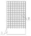
图1是本发明天线的主视结构示意图; Fig. 1 is the front view structure schematic diagram of antenna of the present invention;
图2是本发明天线的后视结构示意图;Fig. 2 is a rear view structural schematic diagram of the antenna of the present invention;
图3是本发明天线的S11图;Fig. 3 is theS11 figure of antenna of the present invention;
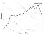
图4是本发明天线的增益图;Fig. 4 is the gain figure of antenna of the present invention;
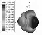
图5是本发明天线的仿真3D方向图;Fig. 5 is the simulation 3D pattern of antenna of the present invention;
图6是测量的本发明天线7GHz的2D共面极化与交叉极化的结果;Fig. 6 is the result of measuring 2D coplanar polarization and cross polarization of the antenna of the present invention at 7 GHz;
图7是测量的本发明天线7.6GHz 的2D共面极化与交叉极化的结果;Fig. 7 is the result of the measured 2D coplanar polarization and cross polarization of the antenna of the present invention at 7.6GHz;
附图中,1、第一阵元,2、第二阵元,3、金属反射层,4、基板,5、第一馈线,6、第二馈线,7、十字型间隙。In the drawings, 1. first array element, 2. second array element, 3. metal reflective layer, 4. substrate, 5. first feeder line, 6. second feeder line, 7. cross-shaped gap.
具体实施方式Detailed ways
参看图1和图2,本发明结构中包括基板4、刻蚀在基板4上表面的超材料制成的天线阵和覆在基板2下表面的金属反射层3,所述金属反射层3上刻蚀有阵列的十字型间隙7,在第二馈线6所在的馈电区域所对应的金属反射层上未刻蚀十字型间隙,刻画的超材料参见背景技术中Le-Wei Li所公开的超材料。本发明中所述天线阵由第一阵元1和第二阵元2串联组成。 1 and 2, the structure of the present invention includes a substrate 4, an antenna array made of metamaterial etched on the upper surface of the substrate 4, and a metal
所述第一阵元1和第二阵元2借助偏离中心的第一馈线5连接,第二阵元2与馈源之间借助偏离中心的第二馈线6连接,所述第二馈线6与第一馈线5与中心偏离的方向是相反的。 The
第一阵元1与第二阵元2之间的距离为介质中的中心波长的0.5~1倍。第一馈线5的特征阻抗与第一阵元1的输入阻抗匹配。 The distance between the
设计传统天线时的假设(每个天线的阻抗是纯实数)在超材料概念天线阵设计中很难被保证。虽然为了增益最好的叠加,两个阵元之间的距离仍然是一个波长(天线排阵的一个要求,为了保证两个天线相位相同),但是馈线和阵元各自的长度不再像传统天线一样是半波长。 The assumption when designing traditional antennas (the impedance of each antenna is a purely real number) is difficult to guarantee in the design of metamaterial conceptual antenna arrays. Although for the best superposition of gain, the distance between the two array elements is still one wavelength (a requirement of the antenna array, in order to ensure that the phases of the two antennas are the same), but the respective lengths of the feeder and the array elements are no longer like traditional antennas Same half wavelength. the
两个阵元之间的第一馈线5的特征阻抗与第一阵元1的输入阻抗匹配,即第一馈线5的特征阻抗基本等于第一阵元1的输入阻抗。总的输入阻抗于是接近50Ω(两个单个天线阻抗都大于50Ω,并联起来就接近50Ω),与天线阵的输入阻抗一致。这个分步匹配技术使输入阻抗随频率变化缓慢,从而导致宽带宽的特性。 The characteristic impedance of the
本实施例中基板4 是Duroid,相对介电常数为2.2,厚度31mil。每个阵元覆盖的区域大小是12mm×16mm。第一馈线5和第二馈线6是向着相反方向偏离阵元中心的。两个阵元之间的距离,也就是第一馈线5与第一阵元4的长度之和为传输介质中的一个波长长度。为了维持能量传输特性,第二馈线6下方的金属反射层并未被蚀刻十字型缝隙;为了维持第一阵元1的辐射特性,第一馈线5下方的金属反射层是蚀刻的。 Substrate 4 is Duroid in the present embodiment, and relative permittivity is 2.2, and thickness 31mil. The size of the area covered by each array element is 12mm×16mm. The
制造本实施例的二元超材料天线阵,阵元尺寸为12mm×16mm;第一馈线的长度为12mm、宽度为0.65mm;第二馈线的长度为13.4mm、宽度为2.42mm,基板4的尺寸为72.4mm×41mm。S11的仿真、测量结果比较见图3,从图中可以看出,-10dB时带宽在3.9GHz到7.7GHz之间,相对带宽到达68%,相比而言单个阵元的相对带宽是46%(参见Le-Wei Li, Ya-Nan Li, Tat Soon Yeo, Juan R. Mosig, Olivier J. F. Martin, “A broadband and high-gain metamaterial microstrip antenna,” Appl. Phys. Lett., vol. 96, No. 16, p. 164101, Apr 2010)。 Manufacture the binary metamaterial antenna array of this embodiment, the array element size is 12mm × 16mm; the length of the first feeder is 12mm, the width is 0.65mm; the length of the second feeder is 13.4mm, the width is 2.42mm, the substrate 4 The size is 72.4mm x 41mm. The comparison of simulation and measurement results of S11 is shown in Figure 3. It can be seen from the figure that at -10dB, the bandwidth is between 3.9GHz and 7.7GHz, and the relative bandwidth reaches 68%. Compared with the relative bandwidth of a single array element, it is 46%. (See Le-Wei Li, Ya-Nan Li, Tat Soon Yeo, Juan R. Mosig, Olivier J. F. Martin, “A broadband and high-gain metamaterial microstrip antenna,” Appl. Phys. Lett., vol. 96 , No. 16, p. 164101, Apr 2010). the
图4是测试的4GHz到8GHz的峰值增益,除了3.9GHz~4.65GHz,带宽内峰值增益都高于3.9dB。在7GHz和7.6GHz有极大值。 Figure 4 shows the measured peak gain from 4GHz to 8GHz. Except for 3.9GHz~4.65GHz, the peak gain within the bandwidth is higher than 3.9dB. There are maxima at 7GHz and 7.6GHz. the
图5是本实施例天线阵的仿真3D方向图。由于两个阵元方向图的叠加,天线主瓣也是向前的。本发明使用了超材料做串联馈电阵,为了继承其宽带宽、高增益的特点,使用了偏离中心的馈线,两个馈线在不同的方向偏离保证了其增益最大化。所以使增益和带宽进一步提高,带宽远大于普通微带二元串馈天线。 Fig. 5 is a simulated 3D direction diagram of the antenna array in this embodiment. Due to the superposition of the pattern of the two array elements, the main lobe of the antenna is also forward. The present invention uses metamaterials as the series feed array, and in order to inherit its characteristics of wide bandwidth and high gain, an off-center feeder is used, and the two feeders deviate in different directions to ensure the maximum gain. Therefore, the gain and bandwidth are further improved, and the bandwidth is much larger than that of the ordinary microstrip binary series antenna. the
图6和图7 是测量的7GHz和7.6GHz的2D共面极化与交叉极化结果,从图中可知:在主要辐射方向(即零度方向)共面极化和交叉极化相差大约20dB,其极化效果非常好。 Figure 6 and Figure 7 are the measured results of 2D coplanar polarization and cross polarization at 7GHz and 7.6GHz. It can be seen from the figure that the difference between coplanar polarization and cross polarization in the main radiation direction (ie zero degree direction) is about 20dB. Its polarization effect is very good. the
Claims (5)
Priority Applications (1)
| Application Number | Priority Date | Filing Date | Title |
|---|---|---|---|
| CN2012101922445ACN102881999A (en) | 2012-06-12 | 2012-06-12 | Broadband and high-gain metamaterial antenna |
Applications Claiming Priority (1)
| Application Number | Priority Date | Filing Date | Title |
|---|---|---|---|
| CN2012101922445ACN102881999A (en) | 2012-06-12 | 2012-06-12 | Broadband and high-gain metamaterial antenna |
Publications (1)
| Publication Number | Publication Date |
|---|---|
| CN102881999Atrue CN102881999A (en) | 2013-01-16 |
Family
ID=47483235
Family Applications (1)
| Application Number | Title | Priority Date | Filing Date |
|---|---|---|---|
| CN2012101922445APendingCN102881999A (en) | 2012-06-12 | 2012-06-12 | Broadband and high-gain metamaterial antenna |
Country Status (1)
| Country | Link |
|---|---|
| CN (1) | CN102881999A (en) |
Cited By (1)
| Publication number | Priority date | Publication date | Assignee | Title |
|---|---|---|---|---|
| CN110311231A (en)* | 2018-03-27 | 2019-10-08 | 华为技术有限公司 | Antenna array, connection method of antenna array and radar module |
Citations (3)
| Publication number | Priority date | Publication date | Assignee | Title |
|---|---|---|---|---|
| CN101388491A (en)* | 2008-10-24 | 2009-03-18 | 苏州中科集成电路设计中心有限公司 | Micro-strip dual-unit array transceiving antenna for RFID reader |
| WO2011106881A1 (en)* | 2010-03-05 | 2011-09-09 | University Of Windsor | Radar system and method of manufacturing same |
| WO2012011958A1 (en)* | 2010-07-23 | 2012-01-26 | Sensormatic Electronics, LLC | Combination radio frequency identification and electronic article surveillance antenna system |
- 2012
- 2012-06-12CNCN2012101922445Apatent/CN102881999A/enactivePending
Patent Citations (3)
| Publication number | Priority date | Publication date | Assignee | Title |
|---|---|---|---|---|
| CN101388491A (en)* | 2008-10-24 | 2009-03-18 | 苏州中科集成电路设计中心有限公司 | Micro-strip dual-unit array transceiving antenna for RFID reader |
| WO2011106881A1 (en)* | 2010-03-05 | 2011-09-09 | University Of Windsor | Radar system and method of manufacturing same |
| WO2012011958A1 (en)* | 2010-07-23 | 2012-01-26 | Sensormatic Electronics, LLC | Combination radio frequency identification and electronic article surveillance antenna system |
Non-Patent Citations (1)
| Title |
|---|
| LE-WEI LI等: "Design of a Novel Rectangular Patch Antenna with Planar Metamaterial Patterned Substrate", 《PROCEEDINGS OF IWAT2008, CHIBA, JAPAN》* |
Cited By (2)
| Publication number | Priority date | Publication date | Assignee | Title |
|---|---|---|---|---|
| CN110311231A (en)* | 2018-03-27 | 2019-10-08 | 华为技术有限公司 | Antenna array, connection method of antenna array and radar module |
| CN110311231B (en)* | 2018-03-27 | 2021-10-15 | 华为技术有限公司 | Antenna array, connection method of antenna array and radar module |
Similar Documents
| Publication | Publication Date | Title |
|---|---|---|
| CN110323575B (en) | Dual-polarized strongly coupled ultra-wideband phased array antenna loaded with electromagnetic metamaterials | |
| Abdel-Wahab et al. | Wide-bandwidth 60-GHz aperture-coupled microstrip patch antennas (MPAs) fed by substrate integrated waveguide (SIW) | |
| US9142889B2 (en) | Compact tapered slot antenna | |
| CN108963443A (en) | A kind of antenna and encapsulating antenna structure | |
| CN107834212B (en) | High-gain high-order die cavity array antenna based on novel super surface | |
| CN107768819B (en) | An end-fire millimeter-wave antenna with controllable radiation direction | |
| CN107634337B (en) | Patch Array Antenna Based on Soft Surface Structure | |
| CN114156643B (en) | Ultra-wideband millimeter wave planar spiral circularly polarized antenna array | |
| CN107134653A (en) | Plane compact type slot antenna array based on substrate integration wave-guide resonator | |
| CN105958191B (en) | Dual-polarized high-gain MIMO antenna based on aperiodic artificial magnetic conductor structure | |
| KR101630674B1 (en) | Double dipole quasi-yagi antenna using stepped slotline structure | |
| CN107240770A (en) | A kind of periodic spatial wave resistance for micro-strip antenna array keeps off decoupling arrangements | |
| CN107437657A (en) | High-gain microstrip antenna based on aperiodic electromagnetic bandgap structure | |
| CN110233353B (en) | Metamaterial unit and metamaterial-based double-layer radiation antenna device | |
| Cao et al. | Ka-band multibeam patch antenna array fed by spoof-surface-plasmon-polariton Butler matrix | |
| CN207517869U (en) | A kind of controllable end-fire millimeter wave antenna of radiation direction | |
| CN107978852B (en) | A Broadband Dual Circular Polarization Slot Antenna | |
| CN106299688A (en) | The micro-strip antenna array of the little frequency ratio of broadband dual-frequency double-circle polarization | |
| CN107196069B (en) | Compact Substrate Integrated Waveguide Cavity-Backed Slot Antenna | |
| CN108376841B (en) | A broadband dual-polarized antenna with high front-to-back ratio with sidewall structure | |
| CN102868025A (en) | High-gain omnidirectional antenna | |
| CN108400429A (en) | A kind of ultra wideband dual polarization antenna | |
| Chatterjee et al. | A FSS based corner reflector for performance enhancement of a ribcage dipole antenna | |
| CN102881999A (en) | Broadband and high-gain metamaterial antenna | |
| Arora et al. | Design Analysis and Comparison of HE and E Shaped Microstrip Patch Antennas |
Legal Events
| Date | Code | Title | Description |
|---|---|---|---|
| C06 | Publication | ||
| PB01 | Publication | ||
| C10 | Entry into substantive examination | ||
| SE01 | Entry into force of request for substantive examination | ||
| C12 | Rejection of a patent application after its publication | ||
| RJ01 | Rejection of invention patent application after publication | Application publication date:20130116 |