CN102879973A - Lens holder drive - Google Patents
Lens holder driveDownload PDFInfo
- Publication number
- CN102879973A CN102879973ACN201210244527XACN201210244527ACN102879973ACN 102879973 ACN102879973 ACN 102879973ACN 201210244527X ACN201210244527X ACN 201210244527XACN 201210244527 ACN201210244527 ACN 201210244527ACN 102879973 ACN102879973 ACN 102879973A
- Authority
- CN
- China
- Prior art keywords
- lens holder
- camera shake
- shake correction
- coil
- lens
- Prior art date
- Legal status (The legal status is an assumption and is not a legal conclusion. Google has not performed a legal analysis and makes no representation as to the accuracy of the status listed.)
- Granted
Links
Images


Classifications
- G—PHYSICS
- G02—OPTICS
- G02B—OPTICAL ELEMENTS, SYSTEMS OR APPARATUS
- G02B27/00—Optical systems or apparatus not provided for by any of the groups G02B1/00 - G02B26/00, G02B30/00
- G02B27/64—Imaging systems using optical elements for stabilisation of the lateral and angular position of the image
- G02B27/646—Imaging systems using optical elements for stabilisation of the lateral and angular position of the image compensating for small deviations, e.g. due to vibration or shake
- G—PHYSICS
- G02—OPTICS
- G02B—OPTICAL ELEMENTS, SYSTEMS OR APPARATUS
- G02B7/00—Mountings, adjusting means, or light-tight connections, for optical elements
- G02B7/02—Mountings, adjusting means, or light-tight connections, for optical elements for lenses
- G02B7/04—Mountings, adjusting means, or light-tight connections, for optical elements for lenses with mechanism for focusing or varying magnification
- G02B7/08—Mountings, adjusting means, or light-tight connections, for optical elements for lenses with mechanism for focusing or varying magnification adapted to co-operate with a remote control mechanism
- G—PHYSICS
- G02—OPTICS
- G02B—OPTICAL ELEMENTS, SYSTEMS OR APPARATUS
- G02B7/00—Mountings, adjusting means, or light-tight connections, for optical elements
- G02B7/02—Mountings, adjusting means, or light-tight connections, for optical elements for lenses
- G02B7/04—Mountings, adjusting means, or light-tight connections, for optical elements for lenses with mechanism for focusing or varying magnification
- G02B7/09—Mountings, adjusting means, or light-tight connections, for optical elements for lenses with mechanism for focusing or varying magnification adapted for automatic focusing or varying magnification
- G—PHYSICS
- G03—PHOTOGRAPHY; CINEMATOGRAPHY; ANALOGOUS TECHNIQUES USING WAVES OTHER THAN OPTICAL WAVES; ELECTROGRAPHY; HOLOGRAPHY
- G03B—APPARATUS OR ARRANGEMENTS FOR TAKING PHOTOGRAPHS OR FOR PROJECTING OR VIEWING THEM; APPARATUS OR ARRANGEMENTS EMPLOYING ANALOGOUS TECHNIQUES USING WAVES OTHER THAN OPTICAL WAVES; ACCESSORIES THEREFOR
- G03B13/00—Viewfinders; Focusing aids for cameras; Means for focusing for cameras; Autofocus systems for cameras
- G03B13/32—Means for focusing
- G03B13/34—Power focusing
- G03B13/36—Autofocus systems
- G—PHYSICS
- G03—PHOTOGRAPHY; CINEMATOGRAPHY; ANALOGOUS TECHNIQUES USING WAVES OTHER THAN OPTICAL WAVES; ELECTROGRAPHY; HOLOGRAPHY
- G03B—APPARATUS OR ARRANGEMENTS FOR TAKING PHOTOGRAPHS OR FOR PROJECTING OR VIEWING THEM; APPARATUS OR ARRANGEMENTS EMPLOYING ANALOGOUS TECHNIQUES USING WAVES OTHER THAN OPTICAL WAVES; ACCESSORIES THEREFOR
- G03B3/00—Focusing arrangements of general interest for cameras, projectors or printers
- G03B3/10—Power-operated focusing
- G—PHYSICS
- G03—PHOTOGRAPHY; CINEMATOGRAPHY; ANALOGOUS TECHNIQUES USING WAVES OTHER THAN OPTICAL WAVES; ELECTROGRAPHY; HOLOGRAPHY
- G03B—APPARATUS OR ARRANGEMENTS FOR TAKING PHOTOGRAPHS OR FOR PROJECTING OR VIEWING THEM; APPARATUS OR ARRANGEMENTS EMPLOYING ANALOGOUS TECHNIQUES USING WAVES OTHER THAN OPTICAL WAVES; ACCESSORIES THEREFOR
- G03B5/00—Adjustment of optical system relative to image or object surface other than for focusing
- H—ELECTRICITY
- H04—ELECTRIC COMMUNICATION TECHNIQUE
- H04N—PICTORIAL COMMUNICATION, e.g. TELEVISION
- H04N23/00—Cameras or camera modules comprising electronic image sensors; Control thereof
- H04N23/50—Constructional details
- H04N23/55—Optical parts specially adapted for electronic image sensors; Mounting thereof
- H—ELECTRICITY
- H04—ELECTRIC COMMUNICATION TECHNIQUE
- H04N—PICTORIAL COMMUNICATION, e.g. TELEVISION
- H04N23/00—Cameras or camera modules comprising electronic image sensors; Control thereof
- H04N23/60—Control of cameras or camera modules
- H04N23/68—Control of cameras or camera modules for stable pick-up of the scene, e.g. compensating for camera body vibrations
- H04N23/681—Motion detection
- H04N23/6812—Motion detection based on additional sensors, e.g. acceleration sensors
- H—ELECTRICITY
- H04—ELECTRIC COMMUNICATION TECHNIQUE
- H04N—PICTORIAL COMMUNICATION, e.g. TELEVISION
- H04N23/00—Cameras or camera modules comprising electronic image sensors; Control thereof
- H04N23/60—Control of cameras or camera modules
- H04N23/68—Control of cameras or camera modules for stable pick-up of the scene, e.g. compensating for camera body vibrations
- H04N23/682—Vibration or motion blur correction
- H04N23/685—Vibration or motion blur correction performed by mechanical compensation
- H04N23/687—Vibration or motion blur correction performed by mechanical compensation by shifting the lens or sensor position
- G—PHYSICS
- G03—PHOTOGRAPHY; CINEMATOGRAPHY; ANALOGOUS TECHNIQUES USING WAVES OTHER THAN OPTICAL WAVES; ELECTROGRAPHY; HOLOGRAPHY
- G03B—APPARATUS OR ARRANGEMENTS FOR TAKING PHOTOGRAPHS OR FOR PROJECTING OR VIEWING THEM; APPARATUS OR ARRANGEMENTS EMPLOYING ANALOGOUS TECHNIQUES USING WAVES OTHER THAN OPTICAL WAVES; ACCESSORIES THEREFOR
- G03B2205/00—Adjustment of optical system relative to image or object surface other than for focusing
- G03B2205/0007—Movement of one or more optical elements for control of motion blur
- G03B2205/0015—Movement of one or more optical elements for control of motion blur by displacing one or more optical elements normal to the optical axis
- G—PHYSICS
- G03—PHOTOGRAPHY; CINEMATOGRAPHY; ANALOGOUS TECHNIQUES USING WAVES OTHER THAN OPTICAL WAVES; ELECTROGRAPHY; HOLOGRAPHY
- G03B—APPARATUS OR ARRANGEMENTS FOR TAKING PHOTOGRAPHS OR FOR PROJECTING OR VIEWING THEM; APPARATUS OR ARRANGEMENTS EMPLOYING ANALOGOUS TECHNIQUES USING WAVES OTHER THAN OPTICAL WAVES; ACCESSORIES THEREFOR
- G03B2205/00—Adjustment of optical system relative to image or object surface other than for focusing
- G03B2205/0053—Driving means for the movement of one or more optical element
- G03B2205/0069—Driving means for the movement of one or more optical element using electromagnetic actuators, e.g. voice coils
Landscapes
- Physics & Mathematics (AREA)
- General Physics & Mathematics (AREA)
- Engineering & Computer Science (AREA)
- Multimedia (AREA)
- Signal Processing (AREA)
- Optics & Photonics (AREA)
- Adjustment Of Camera Lenses (AREA)
- Lens Barrels (AREA)
- Studio Devices (AREA)
Abstract
Description
Translated fromChinese技术领域technical field
本发明涉及透镜架驱动装置,尤其涉及修正用便携终端用的小型摄像机拍摄静止图像时产生的相机抖动(camera shake)(振动)以能够拍摄图像不模糊的静止图像的透镜架驱动装置。The present invention relates to a lens holder driving device, and more particularly to a lens holder driving device capable of correcting camera shake (vibration) generated when a still image is taken by a small camera for a portable terminal so that a still image without blurring the image can be taken.
背景技术Background technique
一直以来曾提出各种拍摄静止图像时即使有相机抖动(振动)也能够防止成像面上的图像模糊并能够进行清楚的拍摄的透镜架驱动装置。Conventionally, various lens holder driving devices have been proposed that can prevent image blurring on the imaging surface and enable clear shooting even if there is camera shake (vibration) when taking a still image.
作为相机抖动修正方式,已知有传感器位移方式及透镜位移方式等的“光学式”、通过利用软件进行的图像处理对相机抖动进行修正的“软件修正方式”。导入到便携终端的相机抖动修正方式主要采用软件修正方式。As camera shake correction methods, there are known "optical methods" such as a sensor shift method and a lens shift method, and a "software correction method" in which camera shake is corrected by image processing using software. The camera shake correction method introduced into the portable terminal mainly adopts the software correction method.
软件修正方式公开于例如日本特开平11-64905号公报(以下也称为专利文献1)。在专利文献1中公开的相机抖动修正方法中,根据检测机构的检测结果去除干扰成分,根据去除了该干扰成分的检测信号计算修正摄像装置的相机抖动引起的图像模糊所必要的特定信息,由此在摄像装置静止而没有相机抖动的状态下,摄像图像也处于静止。The software correction method is disclosed in, for example, Japanese Patent Application Laid-Open No. 11-64905 (hereinafter also referred to as Patent Document 1). In the camera shake correction method disclosed in
然而,该专利文献1所公开的“软件修正方式”的相机抖动修正方法与后述的“光学式”相比较,存在画质劣化之类的问题。另外,软件修正方式的相机抖动修正方法由于摄像时间还包含软件处理,因此存在时间变长之类的缺点。However, the camera shake correction method of the "software correction method" disclosed in this
因此,随着近年来高像素化,作为相机抖动修正方式,增加了“光学式”的要求。作为“光学式”的相机抖动修正方式,已知有“传感器位移方式”、“透镜位移方式”、以及“光学单元倾斜方式”。Therefore, as the number of pixels increases in recent years, the demand for an "optical method" has increased as a camera shake correction method. As "optical" camera shake correction methods, there are known "sensor shift method", "lens shift method", and "optical unit tilt method".
传感器位移方式公开于例如日本特开2004-274242号公报(以下也称为专利文献2)。专利文献2所公开的数字摄像机成为摄像元件(CCD)通过驱动器而能够以标准位置(中心)为中心移动的结构。驱动器根据由振动传感器检测出的相机抖动而进行使CCD移动的相机抖动修正。CCD配置在CCD移动部内。CCD通过该CCD移动部而能够在与Z轴正交的XY平面内移动。CCD移动部主要包括:固定设置在壳体上的基座板;相对于基座板在X轴方向上移动的第一滑块;以及相对于第一滑块在Y轴方向上移动的第二滑块这三个部件。The sensor displacement method is disclosed in, for example, Japanese Patent Application Laid-Open No. 2004-274242 (hereinafter also referred to as Patent Document 2). The digital video camera disclosed in Patent Document 2 has a configuration in which an imaging device (CCD) is movable around a standard position (center) by a driver. The driver performs camera shake correction for moving the CCD based on the camera shake detected by the vibration sensor. The CCD is arranged in the CCD moving part. The CCD is movable in the XY plane perpendicular to the Z axis by the CCD moving part. The CCD moving part mainly includes: a base plate fixedly arranged on the housing; a first slider moving in the X-axis direction relative to the base plate; and a second slider moving in the Y-axis direction relative to the first slider. Slider these three components.
然而,专利文献2所公开的“传感器位移方式”导致CCD移动部(可动机构)变大。因此,将传感器位移方式的相机抖动修正装置应用于便携电话用的小型摄像机在尺寸(外形、高度)方面非常困难。However, the "sensor displacement method" disclosed in Patent Document 2 results in an enlarged CCD moving part (movable mechanism). Therefore, it is very difficult in terms of size (outline, height) to apply a sensor shift system camera shake correction device to a compact video camera for a mobile phone.
其次,对透镜位移方式进行说明。Next, the lens shift method will be described.
例如,日本特开2009-145771号公报(以下也称为专利文献3)公开了包含驱动修正透镜的振动修正单元的图像振动修正装置。振动修正单元具备:作为固定部件的基座板;保持修正透镜使其能够移动的可动镜筒;被基座板和可动镜筒挟持的三个球;相对于基座板弹性支撑可动镜筒的多个弹性体;固定在基座板上的两个线圈;以及固定在可动镜筒上的两个磁铁。For example, Japanese Patent Application Laid-Open No. 2009-145771 (hereinafter also referred to as Patent Document 3) discloses an image vibration correction device including a vibration correction unit that drives a correction lens. The vibration correction unit is equipped with: a base plate as a fixed part; a movable lens barrel that holds the correction lens so that it can move; three balls held between the base plate and the movable lens barrel; Multiple elastomers for the lens barrel; two coils fixed to the base plate; and two magnets fixed to the movable lens barrel.
另外,日本特开2006-65352号公报(以下也称为专利文献4)公开了如下“图像模糊修正装置”,该“图像模糊修正装置”通过在相对于光轴的垂直面内相互正交的两个方向上对由多个透镜组构成的摄影光学系统(成像光学系统)中的特定一个透镜组(以下称为“修正透镜”)进行移动控制,从而对图像模糊进行修正。在专利文献4所公开的图像模糊修正装置中,修正透镜经由俯仰(ピッチング)移动框以及偏转移动框,相对于固定框在上下方向(俯仰方向)以及左右方向(偏转方向)上移动自如地支撑。In addition, Japanese Patent Application Laid-Open No. 2006-65352 (hereinafter also referred to as Patent Document 4) discloses an "image blur correction device" in which Image blur is corrected by controlling movement of a specific lens group (hereinafter referred to as "correction lens") in a photographic optical system (imaging optical system) composed of multiple lens groups in two directions. In the image blur correction device disclosed in Patent Document 4, the correction lens is movably supported in the vertical direction (pitch direction) and the left and right direction (yaw direction) with respect to the fixed frame via the pitching (pitching) moving frame and the yaw moving frame. .
日本特开2008-26634号公报(以下也称为专利文献5)公开了如下“相机抖动修正单元”,该“相机抖动修正单元”包含通过在与成像光学系统的光轴相交的方向上移动来修正由成像光学系统形成的图像的模糊的修正光学部件。在专利文献5所公开的修正光学部件中,保持修正透镜的透镜保持框经由仰俯滑块及偏转滑块沿俯仰方向及偏转方向移动自如地支撑在收放筒上。Japanese Patent Application Laid-Open No. 2008-26634 (hereinafter also referred to as Patent Document 5) discloses a "camera shake correction unit" that includes moving in a direction intersecting the optical axis of the imaging optical system to A correction optical component that corrects blurring of an image formed by an imaging optical system. In the correcting optical component disclosed in Patent Document 5, a lens holding frame holding a correcting lens is supported by a retractable tube movably in a pitch direction and a yaw direction via a pitch slider and a yaw slider.
日本特开2006-215095号公报(以下也称为专利文献6)公开了如下“图像模糊修正装置”,该“图像模糊修正装置”能够以小的驱动力使修正透镜移动,能够进行迅速且高精度的图像模糊修正。专利文献6所公开的图像模糊修正装置具备:保持修正透镜的保持框;支撑该保持框使其在第一方向(俯仰方向)上滑动自如的第一滑块;支撑保持框使其在第二方向(偏转方向)上滑动自如的第二滑块;在第一方向上驱动第一滑块的第一线圈马达;以及在第二方向上驱动第二滑块的第二线圈马达。Japanese Unexamined Patent Application Publication No. 2006-215095 (hereinafter also referred to as Patent Document 6) discloses an "image blur correction device" that can move a correction lens with a small driving force and can perform rapid and high-efficiency correction. Precision image blur correction. The image blur correction device disclosed in Patent Document 6 includes: a holding frame that holds the correction lens; a first slider that supports the holding frame so that it can slide freely in a first direction (pitch direction); and supports the holding frame so that it can slide in a second direction. A second slider that can slide freely in one direction (deflection direction); a first coil motor that drives the first slider in the first direction; and a second coil motor that drives the second slider in the second direction.
日本特开2008-15159号公报(以下也称为专利文献7)公开了如下透镜镜筒,该透镜镜筒具备以能够移动的方式设置在与光轴正交的方向上的模糊修正光学系统。在专利文献7所公开的模糊光学系统中,配置在VR主体单元内的可动VR单元保持修正透镜(第三透镜组),以能够移动的方式设置在与光轴正交的XY平面内。Japanese Patent Application Laid-Open No. 2008-15159 (hereinafter also referred to as Patent Document 7) discloses a lens barrel including a blur correction optical system movably provided in a direction perpendicular to the optical axis. In the blurred optical system disclosed in Patent Document 7, a movable VR unit arranged in a VR main unit holds a correction lens (third lens group) and is movably arranged in an XY plane perpendicular to the optical axis.
日本特开2007-212876号公报(以下也称为专利文献8,与US7619838对应)公开了如下“图像模糊修正装置”,该“图像模糊修正装置”通过控制保持在移动框上的修正透镜,以使其能够在相对于透镜系统的光轴而相互正交的第一及第二方向上移动,并通过驱动机构使修正透镜的光轴与透镜系统的光轴一致,从而能够修正图像模糊。Japanese Patent Laid-Open No. 2007-212876 (hereinafter also referred to as Patent Document 8, corresponding to US7619838) discloses the following "image blur correction device", which controls the correction lens held on the moving frame to It can be moved in the first and second directions orthogonal to each other with respect to the optical axis of the lens system, and the optical axis of the correction lens is aligned with the optical axis of the lens system by the driving mechanism, so that image blur can be corrected.
日本特开2007-17957号公报(以下也称为专利文献9)公开了如下“图像模糊修正装置”,该“图像模糊修正装置”利用透镜驱动部向与透镜系统的光轴正交的方向并且相互正交的第一方向及第二方向的动作来驱动用于修正由透镜系统形成的图像的模糊的修正透镜,从而对图像模糊进行修正。在专利文献9所公开的图像模糊修正装置中,透镜驱动部配置在与修正透镜的光轴正交的方向的一侧。Japanese Unexamined Patent Application Publication No. 2007-17957 (hereinafter also referred to as Patent Document 9) discloses an "image blur correction device" that uses a lens driving unit in a direction perpendicular to the optical axis of the lens system and The movement in the first direction and the second direction orthogonal to each other drives the correction lens for correcting the blur of the image formed by the lens system, thereby correcting the image blur. In the image blur correction device disclosed in Patent Document 9, the lens driving unit is disposed on one side in a direction perpendicular to the optical axis of the correction lens.
日本特开2007-17874号公报(以下也称为专利文献10,与US7650065对应)公开了如下“图像模糊修正装置”,该“图像模糊修正装置”通过控制保持在移动框上的修正透镜,以使其能够在与透镜系统的光轴正交的方向并且相互正交第一方向及第二方向上移动,并使修正透镜的光轴与透镜系统的光轴一致,从而能够修正图像模糊。该专利文献10所公开的图像模糊修正装置具备驱动机构,该驱动机构具有能够相对移动的线圈和磁体。线圈及磁体的一方固定在移动框上,另一方固定在支撑移动框使其能够移动的支撑框上。另外,该专利文献10所公开的图像模糊修正装置具备:通过检测磁体的磁力来检测修正透镜的与第一方向相关的位置信息的第一霍尔元件;以及通过检测磁体的磁力来检测修正透镜的与第二方向相关的位置信息的第二霍尔元件。Japanese Patent Application Laid-Open No. 2007-17874 (hereinafter also referred to as
上述的专利文献3~10所公开的“透镜位移方式”的图像模糊修正装置(相机抖动修正装置)均具有对修正透镜在与光轴垂直的平面内进行移动调整的结构。然而,这种结构的图像模糊修正装置(相机抖动修正装置)存在结构复杂、不利于小型化之类的问题。即、与上述传感器位移方式的相机抖动修正装置同样,将透镜位移方式的相机抖动修正装置应用于便携电话用的小型摄像机在尺寸(外形、高度)方面是困难的。The image blur correction devices (camera shake correction devices) of the "lens shift method" disclosed in the above-mentioned Patent Documents 3 to 10 all have a structure in which the correction lens is moved and adjusted in a plane perpendicular to the optical axis. However, the image blur correction device (camera shake correction device) having such a configuration has problems such as a complicated structure and disadvantageous miniaturization. That is, it is difficult in terms of size (shape, height) to apply the camera shake correction device of the lens shift method to a compact video camera for a mobile phone, similarly to the camera shake correction device of the sensor shift method described above.
为了解决上述的问题,提出了以下装置:通过使保持透镜和摄像元件(图像传感器)的透镜模块(摄像机模块)本身摆动,从而对相机抖动(图像模糊)进行修正的相机抖动修正装置(图像模糊修正装置)。在此将这种方式称为“光学单元倾斜方式”。In order to solve the above problems, the following device has been proposed: a camera shake correction device (image blur) that corrects camera shake (image blur) by swinging the lens module (camera module) itself that holds the lens and the imaging element (image sensor) correction device). This method is called "optical unit tilt method" here.
以下对“光学单元倾斜方式”进行说明。The "optical unit tilt method" will be described below.
例如,日本特开2007-41455号公报(以下也称为专利文献11)公开了如下“光学装置的图像模糊修正装置”,该“光学装置的图像模糊修正装置”具备:保持透镜和摄像元件的透镜模块;通过旋转轴可旋转地支撑该透镜模块的框结构;通过对转动轴的被驱动部(转子)施加驱动力而使透镜模块相对于框结构转动的驱动机构(驱动器);以及使驱动机构(驱动器)对转动轴的被驱动部(转子)加力的加力机构(板簧)。框结构由内框和外框构成。驱动机构(驱动器)配置成从与光轴成直角的方向与转动轴的被驱动部(转子)抵接。驱动机构(驱动器)由压电元件和转动轴侧的作用部构成。作用部利用压电元件的纵向振动及弯曲振动来驱动转动轴。For example, Japanese Patent Application Laid-Open No. 2007-41455 (hereinafter also referred to as Patent Document 11) discloses an "image blur correction device for an optical device" including: a lens module; a frame structure that rotatably supports the lens module through a rotating shaft; a driving mechanism (driver) that rotates the lens module relative to the frame structure by applying a driving force to a driven part (rotor) of the rotating shaft; and causing the drive Mechanism (driver) The urging mechanism (leaf spring) that energizes the driven part (rotor) of the rotating shaft. The frame structure consists of an inner frame and an outer frame. The drive mechanism (driver) is arranged so as to abut against the driven portion (rotor) of the rotation shaft from a direction perpendicular to the optical axis. The driving mechanism (actuator) is composed of a piezoelectric element and an action part on the rotating shaft side. The action part drives the rotating shaft by longitudinal vibration and bending vibration of the piezoelectric element.
然而,在专利文献11所公开的“光学单元倾斜方式”的图像模糊修正装置中,必需利用由内框和外框构成的框结构覆盖透镜模块。其结果,存在图像模糊修正装置变得大型之类的问题。However, in the image blur correction device of the "optical unit tilting method" disclosed in Patent Document 11, it is necessary to cover the lens module with a frame structure composed of an inner frame and an outer frame. As a result, there is a problem that the image blur correction device becomes large.
另外,日本特开2007-93953号公报(以下也称为专利文献12)公开了如下“摄像机的相机抖动修正装置”,该“摄像机的相机抖动修正装置”将摄影透镜及图像传感器一体化的摄像机模块收放在箱体的内部,并且以与摄影光轴正交且相互直角相交的第一轴和第二轴为中心摆动自如地在箱体上轴安装摄像机模块,根据由相机抖动传感器检测出的箱体的振动而在箱体内部控制摄像机模块整体的姿势,从而对静止图像摄影时的相机抖动进行修正。专利文献12所公开的摄像机的相机抖动修正装置具备:中框,其以第一轴为中心从内框的外侧摆动自如地支撑固定有摄像机模块的内框;外框,其固定在箱体上,以第二轴为中心从中框的外侧摆动自如地支撑中框;第一驱动机构,其组装在中框上,且根据来自相机抖动传感器(检测俯仰方向的相机抖动的第一传感器模块)的相机抖动信号使内框绕第一轴摆动;以及第二驱动机构,其组装在外框上,根据来自相机抖动传感器(检测偏转方向的相机抖动的第二传感器模块)的相机抖动信号使中框绕第二轴摆动。第一驱动机构包括:第一步进马达;使第一步进马达的旋转减速的第一减速齿轮组;以及,经由与最终级齿轮一体旋转地设置在内框上的第一凸轮从动件而使内框摆动的第一凸轮。第二驱动机构包括:第二步进马达;使第二步进马达的旋转减速的第二减速齿轮组;以及经由与最终级齿轮一体旋转地设置在中框上的第二凸轮从动件而使中框摆动的第二凸轮。In addition, Japanese Patent Application Laid-Open No. 2007-93953 (hereinafter also referred to as Patent Document 12) discloses a "camera shake correction device for a video camera" that integrates a photographic lens and an image sensor into a video camera. The module is housed inside the box, and the camera module is installed on the box to swing freely around the first axis and the second axis that are perpendicular to the photographic optical axis and intersect each other at right angles. According to the camera shake sensor detected The vibration of the cabinet is used to control the posture of the camera module as a whole inside the cabinet, thereby correcting camera shake during still image shooting. The camera shake correction device for a video camera disclosed in
然而,专利文献12所公开的“光学单元倾斜方式”的相机抖动修正装置也必须由内框、中框及外框覆盖摄像机模块。其结果,导致相机抖动修正装置变得大型。并且,“光学单元倾斜方式”由于存在旋转轴,因此产生孔轴之间的摩擦,还存在产生滞后现象之类的问题。However, the camera shake correction device of the "optical unit tilting method" disclosed in
再有,日本特开2009-288770号公报(以下也称为专利文献13,与US2011/097062对应)公开了如下摄影用光学装置,该摄影用光学装置对相对于摄影单元的摇晃修正用的摄影单元驱动机构的结构进行了改良,能够可靠地对摇晃进行修正。在专利文献13所公开的摄影用光学装置中,在固定罩的内侧构成摄影单元(可动模块)、和用于使该摄影单元位移进行摇晃修正的摇晃修正机构。摄影单元是用于使透镜沿光轴方向移动的构件。摄影单元具有:在内侧保持透镜及固定光圈的移动体;使该移动体沿光轴方向移动的透镜驱动机构;以及搭载有驱动机构及移动体的支撑体。透镜驱动机构具备透镜驱动用线圈、透镜驱动用磁体以及磁轭。摄影单元由四根吊线支撑在固定体上。在中间隔着光轴的两侧的两个部位,分别设有两个为一对的摇晃修正用的第一摄影单元驱动机构及第二摄影单元驱动机构。在这些摄影单元驱动机构中,在可动体侧保持有摄影单元驱动用磁体,在固定体侧保持有摄影单元驱动用线圈。Furthermore, Japanese Patent Application Laid-Open No. 2009-288770 (hereinafter also referred to as
然而,在专利文献13所公开的“光学单元倾斜方式”的摄影用光学装置中,除了透镜驱动用磁体以外,还需要摄影单元驱动用磁体。其结果,存在导致摄影用光学装置变得大型的问题。However, in the imaging optical device of the "optical unit tilting method" disclosed in
另外,日本特开2011-107470号公报(以下也称为专利文献14)公开了能够向光轴方向驱动透镜并且对摇晃进行修正的透镜驱动装置。该专利文献14所公开的透镜驱动装置具备:保持透镜且能够向光轴方向(Z方向)移动的第一保持体;保持第一保持体使其能够向Z方向移动的第二保持体;保持第二保持体使其能够向与Z方向大致正交的方向移动的固定体;用于向Z方向驱动第一保持体的第一驱动机构;用于向X方向驱动第二保持体的第二驱动机构;以及用于向Y方向驱动第二保持体的第三驱动机构。第一保持体通过由弹性材料形成的第一支撑部件能够向Z方向移动地支撑在第二保持体上。第二保持体通过由弹性材料形成的第二支撑部件能够向与Z方向大致正交的方向移动地支撑在固定体上。第一驱动机构具备第一驱动用线圈和第一驱动用磁石,第二驱动机构具备第二驱动用线圈和第二驱动用磁石,第三驱动机构具备第三驱动用线圈和第三驱动用磁石。In addition, Japanese Patent Application Laid-Open No. 2011-107470 (hereinafter also referred to as Patent Document 14) discloses a lens driving device capable of driving a lens in the optical axis direction and correcting shake. The lens driving device disclosed in
在该专利文献14所公开的透镜驱动装置中,作为驱动机构,需要第一至第三驱动机构这三种驱动机构,由于第一至第三驱动机构的各个分别由各个线圈和磁石构成,因此存在部件件数增加之类的问题。In the lens drive device disclosed in
日本特开2011-113009号公报(以下也称为专利文献15)公开了如下透镜驱动装置,该透镜驱动装置的基本结构与上述专利文献14所公开的透镜驱动装置同样,作为第二支撑部件而使用多个金属丝,并具备用于防止金属丝的纵弯曲的纵弯曲防止部件。金属丝形成为直线状,第二保持体通过金属丝而能够向与Z方向大致正交的方向移动地支撑着。纵弯曲防止部件由弹性部件形成,以比金属丝的纵弯曲载荷小的力在Z方向上弹性变形。更具体地说,纵弯曲防止部件由形成于第一支撑部件的板簧上的线固定部构成。在向第二保持体等的可动部分施加下方向的力时,线固定部会向下方向弹性变形。Japanese Unexamined Patent Application Publication No. 2011-113009 (hereinafter also referred to as Patent Document 15) discloses a lens driving device whose basic structure is the same as that of the lens driving device disclosed in
在该专利文献15所公开的透镜驱动装置中,也与上述专利文献14所公开的透镜驱动装置同样,存在部件件数增加之类的问题。另外,专利文献15所公开的透镜驱动装置只不过防止对金属丝施加压缩的方向的力而使金属丝纵弯曲。换言之,在专利文献15所公开的透镜驱动装置中,关于对金属丝施加拉伸方向的力而有可能使金属丝断裂的情况,没有任何考虑。Also in the lens driving device disclosed in Patent Document 15, similarly to the lens driving device disclosed in
于是,本发明的发明人提出了通过将自动调焦(AF)用透镜驱动装置用的永久磁铁还兼用作相机抖动修正装置用的永久磁铁,从而能够实现小型且低高度的相机抖动修正装置(参照日本特开2011-65140号公报(以下也称为专利文献16))。Therefore, the inventors of the present invention have proposed that a small and low-profile camera shake correction device can be realized by using the permanent magnet for the lens driving device for autofocus (AF) also as the permanent magnet for the camera shake correction device ( See JP-A-2011-65140 (hereinafter also referred to as Patent Document 16)).
专利文献16所公开的相机抖动修正装置由于通过使收放在AF用透镜驱动装置中的透镜筒本身移动来对相机抖动进行修正,因此称为“筒位移方式”的相机抖动修正装置。另外,该“筒位移方式”的相机抖动修正装置分为永久磁铁移动(可动)的“移动磁体方式”、和线圈移动(可动)的“移动线圈方式”。The camera shake correction device disclosed in
专利文献16在其第二实施方式中公开了如下结构:作为“移动磁体方式”的相机抖动修正装置具备永久磁铁,该永久磁铁由沿光轴方向上下分离地配置的四片第一永久磁铁片和四片第二永久磁铁片构成,在上侧的四片第一永久磁铁片和下侧的四片第二永久磁铁片之间配置有相机抖动修正用线圈。即、该第二实施方式是包含由总计八片永久磁铁片构成的永久磁铁的“移动磁体方式”的相机抖动修正装置。In its second embodiment,
在专利文献16所公开的相机抖动修正装置中,基座隔开间隔地配置在自动调焦用透镜驱动装置的底面部,在该基座的外周部固定有多个吊线的一端。多个吊线的另一端牢固地固定在自动调焦用透镜驱动装置上。In the camera shake correction device disclosed in
在专利文献16所公开的相机抖动修正装置中,由于永久磁铁由八片永久磁铁片构成,因此存在部件件数变多之类的问题。另外,由于相机抖动修正用线圈配置在上侧的四片第一永久磁铁片与下侧的四片第二永久磁铁片之间,因此还存在组装上花费时间和劳力之类的问题。In the camera shake correction device disclosed in
另外,日本特开2011-85666号公报(以下也称为专利文献17)还公开了兼用AF控制用磁体和模糊控制用磁体的透镜驱动装置。专利文献17所公开的透镜驱动装置具有:具备配置在透镜的外周的第一线圈(AF用线圈)的透镜架;具有与第一线圈相对的第一面并固定磁体的磁体保持部件;连结透镜架和磁体保持部件而且支撑透镜架使其相对于磁体能够向光轴方向移动的弹簧;以及与垂直于磁体的第一面的第二面相对地固定有第二线圈(防抖动用线圈)的基座部件。将透镜保持单元保持在基座部件上使其能够在与光轴垂直的方向上相对移动,该透镜保持单元具有透镜架、磁体、磁体保持部件、以及弹簧。In addition, Japanese Patent Application Laid-Open No. 2011-85666 (hereinafter also referred to as Patent Document 17) also discloses a lens driving device that uses both an AF control magnet and a blur control magnet. The lens driving device disclosed in Patent Document 17 includes: a lens holder having a first coil (coil for AF) arranged on the outer periphery of the lens; a magnet holding member having a first surface opposite to the first coil and fixing a magnet; A frame and a magnet holding member and a spring that supports the lens frame so that it can move in the direction of the optical axis relative to the magnet; Base parts. A lens holding unit is held on a base member so as to be relatively movable in a direction perpendicular to an optical axis, and has a lens holder, a magnet, a magnet holding member, and a spring.
在专利文献17所公开的透镜驱动装置中,作为第六实施方式,公开了在卷绕的一个防抖动用线圈的间隙配置有位置检测传感器的结构。作为位置检测传感器,使用霍尔元件。另外,用设置在固定部的四个角上的吊线保持透镜保持单元。即、吊线的一端固定在固定部的四个角上,吊线的另一端牢固地固定在透镜保持单元上。In the lens driving device disclosed in Patent Document 17, as a sixth embodiment, a configuration in which a position detection sensor is arranged in a gap between one wound anti-shake coil is disclosed. As a position detection sensor, a Hall element is used. In addition, the lens holding unit is held by suspension wires provided at the four corners of the fixing portion. That is, one end of the suspension wire is fixed to the four corners of the fixing part, and the other end of the suspension wire is firmly fixed to the lens holding unit.
在专利文献17所公开的透镜驱动装置中,将位置检测传感器配置在防抖动用线圈(第二线圈)的间隙。并且,如上所述,作为位置检测传感器而使用霍尔元件。在将霍尔元件配置在防抖动用线圈(第二线圈)的间隙(即、环部中)的情况下,存在霍尔元件受到由防抖动用线圈(第二线圈)中流动的电流产生的磁场引起的恶劣影响之类的问题。即、如后文参照图5至图10详细说明的那样,在透镜驱动装置(驱动器)的一次共振以上,磁体(永久磁铁)的动作与第二线圈(防抖动用线圈)中流动的电流的相位错开180度,成为相反相位。其结果,存在导致霍尔元件的输出上产生共振之类的问题。In the lens drive device disclosed in Patent Document 17, the position detection sensor is arranged in a gap between the anti-shake coil (second coil). Furthermore, as described above, a Hall element is used as the position detection sensor. When the Hall element is arranged in the gap (that is, in the ring portion) of the anti-shake coil (second coil), there is a possibility that the Hall element receives the current flowing through the anti-shake coil (second coil). Problems such as adverse effects caused by magnetic fields. That is, as will be described in detail later with reference to FIGS. The phases are shifted by 180 degrees and become opposite phases. As a result, there is a problem that resonance occurs at the output of the Hall element.
发明内容Contents of the invention
因此,本发明的目的在于提供一种透镜架驱动装置,其能够避免作为位置检测传感器的霍尔元件受到由流动于线圈中的电流产生的磁场引起的恶劣影响。Therefore, an object of the present invention is to provide a lens holder driving device capable of preventing a Hall element serving as a position detection sensor from being adversely affected by a magnetic field generated by a current flowing through a coil.
本发明的其他目的随着说明的进展可清楚。Other objects of the invention will become apparent as the description proceeds.
若对本发明例示的方式的要点进行叙述,则透镜架驱动装置具有:使保持透镜筒的透镜架沿光轴移动的自动调焦用透镜架驱动部;以及通过使该自动调焦用透镜架驱动部在与光轴正交而且相互正交的第一方向及第二方向上移动,从而对相机抖动进行修正的相机抖动修正部。根据本发明例示的方式,自动调焦用透镜架驱动部具备:固定在透镜架上的聚焦线圈;永久磁铁,该永久磁铁由多个永久磁铁片构成,该多个永久磁铁片分别具有与该聚焦线圈相对的第一面,相对于光轴配置在该聚焦线圈的半径方向外侧,且在第一方向及第二方向上相对;磁铁架,该磁铁架配置在透镜架的外周并保持永久磁铁,并且具有在光轴方向上相对的第一端及第二端;以及第一及第二板簧,该第一及第二板簧分别安装在磁铁架的第一及第二端,在将透镜架在径向上定位的状态下,能够使透镜架在光轴方向上位移地支撑透镜架。相机抖动修正部具有:固定部,该固定部配置在与第二板簧近接的位置上,且在光轴方向上与自动调焦用透镜架驱动部分离;支撑部件,该支撑部件相对于该固定部支撑自动调焦用透镜架驱动部使其能够在第一方向及第二方向上摆动;相机抖动修正用线圈,该相机抖动修正用线圈由分别与垂直于多个永久磁铁片的第一面的第二面相对地配置在固定部上的多个相机抖动修正用线圈部构成,具有配置在第一方向及第二方向上的特定相机抖动修正用线圈部,该特定的相机抖动修正用线圈部的各个以在相对的永久磁铁片的长度方向上分离的方式,被分割为多个线圈部分;以及多个霍尔元件,该多个霍尔元件在特定的相机抖动修正用线圈部的各个的、多个线圈部分的分离的部位,配置在固定部上。When describing the gist of the exemplified form of the present invention, the lens holder driving device has: a lens holder driving section for autofocus that moves the lens holder holding the lens barrel along the optical axis; A camera shake correction part that corrects camera shake by moving the part in a first direction and a second direction that are perpendicular to the optical axis and are perpendicular to each other. According to the exemplified mode of the present invention, the lens holder driving unit for automatic focusing includes: a focusing coil fixed on the lens holder; The opposite first surface of the focusing coil is arranged on the outside of the radial direction of the focusing coil relative to the optical axis, and is opposite in the first direction and the second direction; the magnet holder is arranged on the outer periphery of the lens holder and holds a permanent magnet , and have a first end and a second end opposite in the direction of the optical axis; In the state where the lens holder is positioned in the radial direction, the lens holder is supported so that the lens holder can be displaced in the optical axis direction. The camera shake correcting unit includes: a fixing unit disposed close to the second leaf spring and separated from the autofocus lens holder driving unit in the optical axis direction; and a supporting member relatively to the second plate spring. The fixed part supports the lens holder driving part for autofocus so that it can swing in the first direction and the second direction; the camera shake correction coil is composed of first magnets perpendicular to the plurality of permanent magnet pieces, respectively. The second surface of the surface is composed of a plurality of camera shake correction coil parts arranged oppositely on the fixed part, and has a specific camera shake correction coil part arranged in the first direction and the second direction. Each of the coil parts is divided into a plurality of coil parts in such a manner as to be separated in the longitudinal direction of the opposing permanent magnet pieces; and a plurality of Hall elements in a specific camera shake correction coil part Individual, separate locations of the plurality of coil parts are arranged on the fixing part.
附图说明Description of drawings
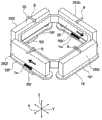
图1是本发明的第一实施方式的透镜架驱动装置的外观立体图。FIG. 1 is an external perspective view of a lens holder driving device according to a first embodiment of the present invention.
图2是图1所示的透镜架驱动装置的局部纵剖视图。Fig. 2 is a partial longitudinal sectional view of the lens holder driving device shown in Fig. 1 .
图3是表示图1所示的透镜架驱动装置的分解立体图。FIG. 3 is an exploded perspective view showing the lens holder driving device shown in FIG. 1 .
图4是表示图1所示的透镜架驱动装置所使用的、线圈基板和形成于该线圈基板上的相机抖动修正用线圈的立体图。4 is a perspective view showing a coil substrate used in the lens holder driving device shown in FIG. 1 and a camera shake correction coil formed on the coil substrate.
图5是表示相关磁路与霍尔元件之间的关系的立体图。Fig. 5 is a perspective view showing the relationship between the relevant magnetic circuit and the Hall element.
图6是表示相关磁路与霍尔元件之间的关系的纵剖视图。Fig. 6 is a longitudinal sectional view showing the relationship between the relevant magnetic circuit and the Hall element.
图7是表示将AF单元在前后方向X位移的情况下的、相关磁路与霍尔元件之间的关系的纵剖视图。7 is a vertical cross-sectional view showing the relationship between the relevant magnetic circuit and the Hall element when the AF unit is displaced in the front-rear direction X.
图8是表示相关磁路中的前侧霍尔元件的频率特性的图。FIG. 8 is a graph showing frequency characteristics of a front Hall element in a relevant magnetic circuit.
图9A、图9B、以及图9C是分别表示图8的区域I、区域II、以及区域III中的利用前侧永久磁铁片产生的磁场B的磁通密度a,利用前侧相机抖动修正用线圈中流动的第一IS电流IIS1产生的磁场BI1的磁通密度b,以及由前侧霍尔元件检测的总的磁通密度(a+b)的大小与相位关系的图。Fig. 9A, Fig. 9B, and Fig. 9C respectively show the magnetic flux density a of the magnetic field B generated by the front side permanent magnet piece in the area I, area II, and area III of Fig. 8, and the front side camera shake correction coil The figure of the magnetic flux density b of the magnetic field BI1 generated by the first IS current IIS1 flowing in the middle, and the magnitude and phase relationship of the total magnetic flux density (a+b) detected by the front-side Hall element.
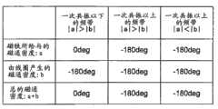
图10是将图9A~9C的关系表示为表格的图。FIG. 10 is a diagram showing the relationship of FIGS. 9A to 9C as a table.
图11是表示图1所示的透镜架驱动装置所使用的磁路与霍尔元件之间的关系的立体图。FIG. 11 is a perspective view showing a relationship between a magnetic circuit and a Hall element used in the lens holder driving device shown in FIG. 1 .
图12是表示图11所示的磁路与霍尔元件之间的关系的纵剖视图。FIG. 12 is a vertical cross-sectional view showing the relationship between the magnetic circuit shown in FIG. 11 and the Hall element.
图13是表示将AF单元在前后方向X位移的情况下的、图11所示的磁路与霍尔元件之间的关系的纵剖视图。13 is a longitudinal sectional view showing the relationship between the magnetic circuit shown in FIG. 11 and the Hall element when the AF unit is displaced in the front-rear direction X. FIG.
图14是表示图13的线XIV-XIV的剖视图。FIG. 14 is a cross-sectional view taken along line XIV-XIV in FIG. 13 .
图15是表示图11所示的磁路中的、前侧霍尔元件的频率特性的图。FIG. 15 is a graph showing frequency characteristics of a front Hall element in the magnetic circuit shown in FIG. 11 .
图16A、图16B、以及图16C是分别表示图15的区域I、区域II、以及区域III中的、利用前侧永久磁铁片产生的磁场B的磁通密度a,前侧相机抖动修正用线圈部中流动的第一IS电流IIS1产生的磁场BI1的磁通密度b,以及由前侧霍尔元件检测的总的磁通密度(a+b)的大小与相位关系的图。16A, FIG. 16B, and FIG. 16C respectively show the magnetic flux density a of the magnetic field B generated by the front permanent magnet piece in the area I, area II, and area III of FIG. 15, and the front side camera shake correction coil The magnetic flux density b of the magnetic field BI1 generated by the first IS current IIS1 flowing in the section, and the magnitude and phase relationship of the total magnetic flux density (a+b) detected by the front-side Hall element.
图17是将图16A~16C的关系表示为表格的图。FIG. 17 is a diagram showing the relationship of FIGS. 16A to 16C as a table.
图18是表示图11所示的磁路中的、永久磁铁的一片永久磁铁片、和配置在其周围的聚焦线圈及相机抖动修正用线圈部的配置关系的剖视图。18 is a cross-sectional view showing the arrangement relationship of one permanent magnet piece of the permanent magnet and the focusing coil and the camera shake correction coil portion arranged around it in the magnetic circuit shown in FIG. 11 .
图19是放大表示将图1所示的透镜架驱动装置所使用的吊线的第二端部固定在上侧板簧上的部分的局部立体图。19 is an enlarged partial perspective view showing a portion where the second end portion of the suspension wire used in the lens holder driving device shown in FIG. 1 is fixed to the upper leaf spring.
图20是图19所示的进行固定的部分的局部剖视图。Fig. 20 is a partial cross-sectional view of a part shown in Fig. 19 for fixing.
图21是从背面侧观察图1所示的透镜架驱动装置所使用的、组合了线圈基板与柔性印制基板(FPC)的结构体的立体图。21 is a perspective view of a structure combining a coil substrate and a flexible printed circuit board (FPC) used in the lens holder driving device shown in FIG. 1 as viewed from the rear side.
图22是表示在图1所示的透镜架驱动装置中省略了屏蔽罩的状态的俯视图。22 is a plan view showing a state in which a shield cover is omitted in the lens holder driving device shown in FIG. 1 .
图23是放大表示在图22中的构成聚焦线圈的线材末端部的捆扎部分的局部放大立体图。FIG. 23 is a partially enlarged perspective view showing, in FIG. 22 , the bundled portion of the end portion of the wire constituting the focusing coil.
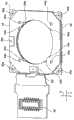
图24是本发明的第二实施方式的透镜架驱动装置的纵剖视图。Fig. 24 is a longitudinal sectional view of a lens holder driving device according to a second embodiment of the present invention.
图25是表示图24所示的透镜架驱动装置的分解立体图。Fig. 25 is an exploded perspective view showing the lens holder driving device shown in Fig. 24 .
具体实施方式Detailed ways
以下,参照附图,对本发明的实施方式进行说明。Hereinafter, embodiments of the present invention will be described with reference to the drawings.
参照图1至图3,对本发明的第一实施方式的透镜架驱动装置10进行说明。图1是透镜架驱动装置10的外观立体图。图2是透镜架驱动装置10的局部纵剖视图。图3是表示透镜架驱动装置10的分解立体图。A lens
在此,如图1至图3所示,使用直角坐标系(X、Y、Z)。在图1至图3所示的状态下,在直角坐标系(X、Y、Z)中,X轴方向为前后方向(进深方向),Y轴方向为左右方向(宽度方向),Z轴方向为上下方向(高度方向)。并且,在图1至图3所示的例子中,上下方向Z为透镜的光轴O方向。还有,在本第二实施方式中,X轴方向(前后方向)也称为第一方向,Y轴方向(左右方向)也称为第二方向。Here, as shown in FIGS. 1 to 3 , a rectangular coordinate system (X, Y, Z) is used. In the states shown in Figures 1 to 3, in the Cartesian coordinate system (X, Y, Z), the X-axis direction is the front-back direction (depth direction), the Y-axis direction is the left-right direction (width direction), and the Z-axis direction is the up-down direction (height direction). In addition, in the examples shown in FIGS. 1 to 3 , the vertical direction Z is the direction of the optical axis O of the lens. In addition, in the second embodiment, the X-axis direction (front-rear direction) is also referred to as the first direction, and the Y-axis direction (left-right direction) is also referred to as the second direction.
但是,在实际的使用状况下,光轴O方向、即、Z轴方向成为前后方向。换言之,Z轴的上方向成为前方向,Z轴的下方向成为后方向。However, in an actual use situation, the optical axis O direction, that is, the Z-axis direction becomes the front-rear direction. In other words, the upward direction of the Z axis becomes the front direction, and the downward direction of the Z axis becomes the rear direction.
图示的透镜架驱动装置10配备在带有能够自动调焦的摄像机的便携电话、智能手机、笔记本电脑、平板电脑、便携式游戏机、Web摄像机、车载用摄像机等的便携终端。透镜架驱动装置10是包含后述的自动调焦用透镜架驱动部20、以及在用便携终端用的小型摄像机拍摄静止图像时修正该自动调焦用透镜架驱动部20所产生的相机抖动(振动)的相机抖动修正部(后述),能够拍摄图像不模糊的图像的装置。透镜架驱动装置10的相机抖动修正部通过使自动调焦用透镜架驱动部20向与光轴O正交且相互正交的第一方向(前后方向)X及第二方向(左右方向)移动,从而对相机抖动进行修正。The illustrated lens
自动调焦用透镜架驱动部20用于使能够安装透镜筒(未图示)的透镜架24(后述)沿光轴O移动。从自动调焦用透镜架驱动部20的底部离开地配置有固定部13。虽然未图示,但在该固定部13的下部(后部)搭载有配置于摄像基板上的摄像元件。该摄像元件对利用透镜筒成像的被拍摄体图像进行拍摄并转换成电信号。摄像元件由例如CCD(charge coupled device)型图像传感器、CMOS(complementary metal oxide semiconductor)型图像传感器等构成。因此,通过自动调焦用透镜架驱动部20、摄像基板、摄像元件的组合,构成摄像机模块。The autofocus lens
固定部13由基座14、线圈基板40、柔性印制基板(FPC)44构成。The fixing
基座14呈外形为四边形且在内部具有圆形开口14a的环形状。The
透镜架驱动装置10的相机抖动修正部具有:在固定部13的四角部固定第一端部161的四根吊线16;以及与后述的自动调焦用透镜架驱动部20的永久磁铁28如后所述相对配置的相机抖动修正用线圈18。The camera shake correction part of the lens
四根吊线16沿光轴O延伸,支撑自动调焦用透镜架驱动部20整体并使其能够在第一方向(前后方向)X及第二方向(左右方向)Y上摆动。四根吊线16的第二端部162如后所述固定在上述自动调焦用透镜架驱动部20的上端部。The four
这样,四根吊线16作为支撑自动调焦用透镜架驱动部20使其相对于固定部13能够在第一方向X及第二方向Y上摆动的支撑部件起作用。In this manner, the four
透镜架驱动装置10的相机抖动修正部如后所述,具备与永久磁铁28相对分离地配置一张四角环形状的线圈基板40。该线圈基板40在中间隔着后述的柔性印制基板(FPC)44而安装在基座14上。在该线圈基板40上形成上述相机抖动修正用线圈18。The camera shake correction unit of the lens
如上所述,通过基座14、线圈基板40和柔性印制基板(FPC)44的组合,构成固定部13。As described above, the fixed
接着,参照图3,对自动调焦用透镜架驱动部20进行说明。此外,自动调焦用透镜架驱动部20也称为AF单元。Next, referring to FIG. 3 , the autofocus lens
自动调焦用透镜架驱动部20具备:具有用于保持透镜筒的筒状部240的透镜架24;以位于筒状部240的周围的方式固定在该透镜架24上的环状的聚焦线圈26;保持与聚焦线圈26相对地配置在聚焦线圈26外侧的永久磁铁28的磁铁架30;以及分别安装在磁铁架30的光轴O方向的第一及第二端30a、30b上的第一及第二板簧32、34。The lens
第一及第二板簧32、34以将透镜架24在径向定位的状态支撑透镜架24使其在光轴O方向上能够位移。在图示的例子中,第一板簧32称为上侧板簧,第二板簧34称为下侧板簧。The first and second plate springs 32 and 34 support the
另外,如上所述,在实际的使用状况中,Z轴方向(光轴O方向)的上方向成为前方向,Z轴方向(光轴O方向)的下方向成为后方向。因此,上侧板簧32也称为前侧弹簧,下侧板簧34也称为后侧弹簧。In addition, as described above, in actual use, the upward direction in the Z-axis direction (direction of the optical axis O) is the front direction, and the downward direction in the Z-axis direction (direction of the optical axis O) is the rearward direction. Therefore, the
磁铁架30呈大致八边筒状。即、磁铁架30具有:八边筒形状的外筒部302;设置在该外筒部302的上端(前端、第一端)30a的八边形的上侧环状端部304;以及设置在外筒部302的下端(后端、第二端)30b的八边形的下侧环状端部306。上侧环状端部304在四角各角分别具有两个共八个向上方突出的上侧突起304a。下侧环状端部306在四角具有四个向下方突出的下侧突起306a。The
聚焦线圈26呈与八边筒状的磁铁架30的形状一致的八边筒状。永久磁铁28由在第一方向(前后方向)X及第二方向(左右方向)Y相互分离地配置在磁铁架30的八边筒形状的外筒部302的、四片矩形状的永久磁铁片282构成。这四片永久磁铁片282与聚焦线圈26隔有间隔地配置。在图示的实施方式中,各永久磁铁片282被磁化成内周端侧为N极、外周端侧为S极。The
上侧板簧(前侧弹簧)32配置在透镜架24的光轴O方向上侧(前侧),下侧板簧(后侧弹簧)34配置在透镜架24的光轴O方向下侧(后侧)。The upper leaf spring (front spring) 32 is arranged on the upper side (front side) of the
上侧板簧(前侧弹簧)32具有:如后所述安装在透镜架24的上端部的上侧内周侧端部322;以及如后所述安装在磁铁架30的上侧环状端部304的上侧外周侧端部324。在上侧内周侧端部322和上侧外周侧端部324之间设有多个上侧臂部326。即、多个臂部326连接上侧内周侧端部322和上侧外周侧端部324。The upper leaf spring (front spring) 32 has: an upper inner
透镜架24的筒状部240在其上端的四角具有向上方突出的四个上侧突起240a。上侧内周侧端部322具有供这四个上侧突起240a分别压入(装入)的四个上侧孔322a。即、透镜架24的筒状部240的四个上侧突起240a分别压入(装入)到上侧板簧32的上侧内周侧端部322的四个上侧孔322a中。The
另一方面,上侧外周侧端部324具有供磁铁架30的八个上侧突起304a分别装入的八个上侧孔324a。即、磁铁架30的八个上侧突起304a分别装入上侧外周侧端部324的八个上侧孔324a中。On the other hand, the upper outer
上侧板簧(前侧弹簧)32在上侧外周侧端部324的四角还具有向半径方向外侧伸出的四个弧状的伸出部328。这四个弧状的伸出部328分别具有供上述四根吊线16的第二端部162插入(嵌入)的四个线固定用孔328a。此外,关于各弧状的伸出部328的详细结构,以后参照图19进行更加详细的说明。The upper leaf spring (front spring) 32 further has four arc-shaped protruding
下侧板簧(后侧弹簧)34具有:如后所述安装在透镜架24的下端部的下侧内周侧端部342;以及如后所述安装在磁铁架30的下侧环状端部306的下侧外周侧端部344。在下侧内周侧端部342与下侧外周侧端部344之间设有多个下侧臂部346。即、多个下侧臂部346连接下侧内周侧端部342和下侧外周侧端部344。The lower leaf spring (rear spring) 34 has: a lower inner
在下侧板簧34的下部配置有实际上具有同一外形的衬垫36。若详细叙述,则衬垫36具有:具有与下侧板簧34的下侧外周侧端部344实际上为同一形状的外环部364;以及具有覆盖下侧板簧34的下侧内周侧端部342及下侧臂部346的形状的内环部362。A packing 36 having substantially the same outer shape is disposed under the
透镜架24的筒状部240在其下端的四角具有向下方突出的四个下侧突起(未图示)。下侧内周侧端部342具有供这四个下侧突起分别压入(装入)的四个下侧孔342a。即、透镜架24的筒状部240的四个下侧突起分别压入(装入)下侧板簧34的下侧内周侧端部342的四个下侧孔342a中。The
另一方面,下侧板簧34的下侧外周侧端部344具有供磁铁架30的四个下侧突起306a分别装入的四个下侧孔344a。衬垫36的外环部364还在与这四个下侧孔344a对应的位置具有供磁铁架30的四个下侧突起306a分别压入的四个下侧孔364a。即、磁铁架30的四个下侧突起306a分别经由下侧板簧34的下侧外周侧端部344的四个下侧孔344a压入到衬垫36的外环部364的四个下侧孔364a中。On the other hand, the lower outer peripheral end portion 344 of the
由上侧板簧32和下侧板簧34构成的弹性部件作为引导透镜架24使其仅能够在光轴O方向上移动的引导机构起作用。上侧板簧32及下侧板簧34的各个由铍青铜、磷青铜等构成。The elastic member composed of the
在透镜架24的筒状部240的内周壁上切有内螺纹(未图示)。另一方面,虽然未图示,但在透镜筒的外周壁上切有与上述内螺纹螺纹结合的外螺纹。因此,要将透镜筒装配在透镜架24上时,通过使透镜筒相对于透镜架24的筒状部240绕光轴O旋转并沿光轴O方向进行螺纹结合,从而将透镜筒收放在透镜架24内,用粘接剂等相互接合。Internal threads (not shown) are cut into the inner peripheral wall of the
如后所述,通过在聚焦线圈26流动自动调焦(AF)电流,并通过永久磁铁28的磁场和流动于聚焦线圈26中的AF电流形成的磁场的相互作用,能够在光轴O方向上对透镜架24(透镜筒)进行位置调整。As will be described later, by flowing an autofocus (AF) current through the
如上所述,自动调焦用透镜架驱动部(AF单元)20由透镜架24、聚焦线圈26、永久磁铁28、磁铁架30、上侧板簧32、下侧板簧34、以及衬垫36构成。As described above, the autofocus lens holder driving unit (AF unit) 20 is composed of the
其次,参照图3,对透镜架驱动装置10的相机抖动修正部进行更加详细的说明。Next, the camera shake correction unit of the lens
如上所述,透镜架驱动装置10的相机抖动修正部具有:在固定部13的四角部固定第一端部161的四根吊线16;以及与上述自动调焦透镜架用驱动部20的永久磁铁28相对地配置的相机抖动修正用线圈18。As mentioned above, the camera shake correction part of the lens
四根吊线16沿光轴O延伸,支撑自动调焦用透镜架驱动部(AF单元)20整体使其能够在第一方向(前后方向)X及第二方向(左右方向)Y上摆动。四根吊线16的第二端部162固定在上述自动调焦用透镜架驱动部20的上端部。The four
若详细叙述,则如上所述,上侧板簧32的四个弧状的伸出部328分别具有供四根吊线16的第二端部162插入(嵌入)的四个线固定用孔328a(参照图3)。在这四个线固定用孔328a中插入(嵌入)四根吊线16的第二端部162,通过粘接剂或焊锡等固定。If described in detail, as described above, the four arc-shaped protruding
此外,在图示的例子中,各弧上的伸出部328呈L字状,不言而喻,并不限定于此。In addition, in the illustrated example, the protruding
四根吊线16中的两根还用于向聚焦线圈26供电。Two of the four
如上所述,永久磁铁28由在第一方向(前后方向)X及第二方向(左右方向)Y上互相相对地配置的四片永久磁铁片282构成。As described above, the
透镜架驱动装置10的相机抖动修正部具备插入四片永久磁铁片282与基座14之间并分离地配置的一张环状线圈基板40。线圈基板40在其四角具有用于插通四根吊线16而且固定第一端部161的贯通孔40a。在该一张线圈基板40上形成有上述相机抖动修正用线圈18。The camera shake correction unit of the lens
在此,在四片永久磁铁片282中,将相对于光轴O分别配置在前侧、后侧、左侧、以及右侧的永久磁铁片分别称为前侧永久磁铁片282f、后侧永久磁铁片282b、左侧永久磁铁片282l、以及右侧永久磁铁片282r。Here, among the four
还参照图4,在线圈基板40上,作为相机抖动修正用线圈18,形成有四个相机抖动修正用线圈部18f、18b、18l以及18r。Referring also to FIG. 4 , four camera shake
在第一方向(前后方向)X互相相对地配置的两个相机抖动修正用线圈部18f及18b用于使自动调焦用透镜架驱动部(AF单元)20在第一方向(前后方向)X上移动(摆动)。这两个相机抖动修正用线圈部18f及18b统称为第一方向驱动器。此外,在此将相对于光轴O位于前侧的相机抖动修正用线圈部18f称为“前侧相机抖动修正用线圈部”,将相对于光轴O位于后侧的相机抖动修正用线圈部18b称为“后侧相机抖动修正用线圈部”。The two camera shake
另一方面,在第二方向(左右方向)Y互相相对地配置的两个相机抖动修正用线圈部18l及18r用于使自动调焦用透镜架驱动部(AF单元)20在第二方向(左右方向)Y上移动(摆动)。这两个相机抖动修正用线圈部18l及18r称为第二方向驱动器。此外,在此,将相对于光轴O位于左侧的相机抖动修正用线圈部18l称为“左侧相机抖动修正用线圈部”,将相对于光轴O位于右侧的相机抖动修正用线圈部18r称为“右侧相机抖动修正用线圈部”。On the other hand, the two camera shake
如图4所示,在图示的相机抖动修正用线圈18中,前侧相机抖动修正用线圈部18f及左侧相机抖动修正用线圈部18l的各个分别以在相对的前侧永久磁铁片282f及左侧永久磁铁片282l的长度方向的中央分离的方式,分割成两个线圈部分。即、前侧相机抖动修正用线圈部18f由靠左的线圈部分18fl和靠右的线圈部分18fr构成。同样,左侧相机抖动修正用线圈部18l由靠前的线圈部分18lf和靠后的线圈部分18lb构成。As shown in FIG. 4 , in the illustrated camera
换言之,前侧相机抖动修正用线圈部18f及左侧相机抖动修正用线圈部18l的各个由两个环形部分构成,相对于此,后侧相机抖动修正用线圈部18b及右侧相机抖动修正用线圈部18r的各个由一个环形部分构成。In other words, each of the front camera shake
这样,四个相机抖动修正用线圈部18f、18b、18l及18r中的、配置在第一方向X及第二方向上的特定的两个相机抖动修正线圈部18f及18l的各个以在相对的永久磁铁片282f及282l的长度方向的中央分离的方式,分割成两个线圈部分18fl、18fr及18lf、18lb。In this way, among the four camera shake
这样构成的四个相机抖动修正用线圈部18f、18b、18l及18r用于与永久磁铁28协作地在X轴方向(第一方向)及Y轴方向(第二方向)上驱动自动调焦用透镜架驱动部(AF单元)20整体。另外,相机抖动修正用线圈部18f、18b、18l及18r与永久磁铁28的组合作为音圈马达(VCM)起作用。The four camera shake
这样,图示的透镜架驱动装置10的相机抖动修正部通过使收放在自动调焦用透镜架驱动部(AF单元)20的透镜筒本身在第一方向(前后方向)X及第二方向(左右方向)Y移动,从而修正相机抖动。因此,透镜架驱动装置10的相机抖动修正部称为“筒位移方式”的相机抖动修正部。In this way, the camera shake correction unit of the illustrated lens
返回图3,透镜架驱动装置10还具备覆盖自动调焦用透镜架驱动部(AF单元)20的屏蔽罩42。屏蔽罩42具有覆盖自动调焦用透镜架驱动部(AF单元)20的外周侧面的四角筒部422、以及覆盖自动调焦用透镜架驱动部(AF单元)20的上表面的环状的上侧端部424。上侧端部424具有与光轴O同心的圆形开口424a。Returning to FIG. 3 , the lens
图示的透镜架驱动装置10的相机抖动修正部还具备用于检测自动调焦用透镜架驱动部(AF单元)20相对于基座14(固定部13)的位置的位置检测机构50。图示的位置检测机构50由磁式位置检测机构构成,该磁式位置检测机构由安装在基座14上的两个霍尔元件50f、50l构成(参照图11)。这两个霍尔元件50f、50l如后所述,分别与四片永久磁铁片282中的两片分离地相对配置。如图2所示,各霍尔元件50f、50l以横跨永久磁铁片282的N极至S极的方向的方式配置。The camera shake correction unit of the illustrated lens
在图示的例子中,一方的霍尔元件50f相对于光轴O配置在第一方向(前后方向)X的前侧,因此称为前侧霍尔元件。另一方的霍尔元件50l相对于光轴O配置在第二方向(左右方向)Y的左侧,因此称为左侧霍尔元件。In the illustrated example, one
前侧霍尔元件50f在具有被分割的两个线圈部分18fl、18fr的前侧相机抖动修正用线圈部18f的、两个线圈部分18fl、18fr的分离部位,配置在基座14上。同样地,左侧霍尔元件50l在具有被分割的两个线圈部分18lf、18lb的左侧相机抖动修正用线圈部18l的、两个线圈部分18lf、18lb的分离部位,配置在基座14上。The
这样,两个霍尔元件50f及50l在具有被分割的两个线圈部分18fl、18fr及18lf、18lb的特定的两个相机抖动修正用线圈部18f及18l的、两个线圈部分18fl、18fr及18lf、18lb的分离部位,配置在基座14上。In this way, the two
前侧霍尔元件50f通过检测与之相对的前侧永久磁铁片282f的磁力,来检测伴随第一方向(前后方向)X的移动(摆动)的第一位置。左侧霍尔元件50l通过检测与之相对的左侧永久磁铁片282l的磁力,来检测伴随第二方向(左右方向)Y的移动(摆动)的第二位置。The
参照图5至图7,为了容易理解本发明的第一实施方式的透镜架驱动装置10,对相关的透镜架驱动装置所使用的相关磁路与霍尔元件之间的关系进行说明。图示的相关磁路与霍尔元件之间的关系具有与上述的专利文献17中公开的结构同样的结构(关系)。图5是表示相关磁路与霍尔元件之间的关系的立体图,图6是表示相关磁路与霍尔元件之间的关系的纵剖视图,图7是表示使AF单元20在前后方向X上位移的情况的、相关磁路与霍尔元件之间的关系的纵剖视图。Referring to FIG. 5 to FIG. 7 , in order to easily understand the lens
相关磁路与本实施方式的透镜架驱动装置10所使用的磁路之间的不同点在于,在相关磁路中,在构成相机抖动修正用线圈18’的四个相机抖动修正用线圈部18f'、18b’、18l’及18r’中没有被分隔成两个环形部分的线圈。即、在相关磁路中,四个相机抖动修正用线圈部18f'、18b’、18l’及18r’的各个仅由一个环形部分构成。The difference between the relevant magnetic circuit and the magnetic circuit used in the lens
如上所述,四片永久磁铁片282f、282b、282l及282r的各个磁化成内侧为N极、外侧为S极。图5所示的箭头B表示由这些永久磁铁片产生的磁通的方向。As described above, each of the four
其次,参照图5,对使用相关磁路,在光轴O方向对透镜架24(透镜筒)进行位置调整时的动作进行说明。Next, referring to FIG. 5 , the operation when the position of the lens holder 24 (lens barrel) is adjusted in the direction of the optical axis O using the related magnetic circuit will be described.
例如,在聚焦线圈26中沿逆时针方向流过AF电流。这种情况下,按照弗来明左手定律,在聚焦线圈26上作用上方向的电磁力。其结果,能够使透镜架24(透镜筒)向光轴O方向的上方移动。For example, AF current flows counterclockwise in the
反之,通过在聚焦线圈26中沿顺时针方向流过AF电流,能够使透镜架24(透镜筒)向光轴O方向的下方移动。Conversely, by flowing the AF current clockwise through the
接着,参照图5至图7,对使用相关磁路使自动调焦用透镜架驱动部(AF单元)20整体在第一方向(前后方向)X或第二方向(左右方向)Y上移动时的动作进行说明。Next, referring to FIGS. 5 to 7 , when the entire autofocus lens holder drive unit (AF unit) 20 is moved in the first direction (front-rear direction) X or the second direction (left-right direction) Y using the relevant magnetic circuit, actions are described.
首先,对使自动调焦用透镜架驱动部(AF单元)20整体向第一方向(前后方向)X的后侧移动时的动作进行说明。这种情况下,如图5所示,在前侧相机抖动修正用线圈部18f'沿逆时针方向流过如箭头IIS1所示那样的第一相机抖动修正(IS)电流,在后侧相机抖动修正用线圈部18b’沿顺时针方向流过如箭头IIS2所示那样的第二相机抖动修正(IS)电流。First, the operation when the entire autofocus lens holder drive unit (AF unit) 20 is moved to the rear side in the first direction (front-rear direction) X will be described. In this case, as shown in FIG. 5 , the first camera shake correction (IS) current as indicated by arrow IIS1 flows counterclockwise through the front camera shake
这种情况下,按照弗来明左手定律,在前侧相机抖动修正用线圈部18f'作用前方向的电磁力,在后侧相机抖动修正用线圈部18b’也作用前方向的电磁力。然而,由于这些相机抖动修正用线圈部18f'及18b’固定在基座14(固定部13)上,因此作为其反作用,在自动调焦用透镜架驱动部(AF单元)20整体上作用如图6的箭头FIS1及FIS2所示的、后方向的电磁力。其结果,能够使自动调焦用透镜架驱动部(AF单元)20整体向后方向移动。In this case, according to Fleming's left-hand law, an electromagnetic force in the front direction acts on the front camera shake
反之,通过在前侧相机抖动修正用线圈部18f'沿顺时针方向流过第一IS电流,在后侧相机抖动修正用线圈部18b’沿逆时针方向流过第二IS电流,能够使自动调焦用透镜架驱动部(AF单元)20整体向前方向移动。Conversely, by flowing the first IS current clockwise through the front camera shake
另一方面,通过在左侧相机抖动修正用线圈部18l’沿逆时针方向流过第三IS电流,在右侧相机抖动修正用线圈部18r’沿顺时针方向流过第四IS电流,能够使自动调焦用透镜架驱动部(AF单元)20整体向右方向移动。On the other hand, by flowing the third IS current in the counterclockwise direction through the left camera shake correction coil part 18l' and flowing the fourth IS current in the clockwise direction through the right camera shake
另外,通过在左侧相机抖动修正用线圈部18l’沿顺时针方向流过第三IS电流,在右侧相机抖动修正用线圈部18r’沿逆时针方向流过第四IS电流,能够使自动调焦用透镜架驱动部(AF单元)20整体向左方向移动。In addition, by flowing the third IS current in the clockwise direction through the left camera shake correction coil part 18l' and flowing the fourth IS current in the counterclockwise direction through the right camera shake
这样一来,能够对摄像机的相机抖动进行修正。In this way, camera shake of the video camera can be corrected.
其次,除了图5至图7以外,还参照图8至图10,对使用相关磁路的相关透镜架驱动装置的问题点进行详细说明。Next, referring to FIGS. 8 to 10 in addition to FIGS. 5 to 7 , the problems of the related lens holder driving device using the related magnetic circuit will be described in detail.
如上所述,为了使自动调焦用透镜架驱动部(AF单元)20整体向后方向移动,如图5所示,以在前侧相机抖动修正用线圈部18f'沿逆时针方向流动如箭头IIS1所示的第一IS电流,在后侧相机抖动修正用线圈部18b’沿顺时针方向流动如箭头IIS2所示的第二IS电流的情况为例进行了说明。As described above, in order to move the entire autofocus lens holder drive unit (AF unit) 20 backward, as shown in FIG. The case where the first IS current indicated by IIS1 flows in the clockwise direction through the rear camera shake
这种情况下,如图7所示可知,通过前侧相机抖动修正用线圈部18f'中流动的第一IS电流IIS1产生的磁场BI1、和通过移动后的前侧永久磁铁片282f产生的磁场B为相同相位。用a表示磁场B的磁通密度,用b表示磁场BI1的磁通密度。因此,前侧霍尔元件50f检测磁场B的磁通密度a和磁场BI1的磁通密度b的总的磁通密度(a+b)。In this case, as shown in FIG. 7, it can be seen that the magnetic field B I1 generated by the first IS current IIS1 flowing in the front side camera shake
在此,为了由前侧霍尔元件50f检测自动调焦用透镜架驱动部(AF单元)20的位置,要注意磁场B的磁通密度a和总的磁通密度(a+b)为相同相位是必要的。Here, in order to detect the position of the autofocus lens holder drive unit (AF unit) 20 with the
图8是表示相关磁路中的前侧霍尔元件50f的频率特性的图。在图8中,横轴表示频率(Frequency)(Hz),左侧纵轴表示增益(Gain)(dB),右侧纵轴表示相位(Phase)(deg)。另外,在图8中,实线表示增益特性,单点划线表示相位特性。FIG. 8 is a graph showing the frequency characteristics of the
从图8可知,前侧霍尔元件50f的频率特性分为区域I、区域II、区域III。区域I是驱动器的一次共振以下的频带,是频率较低的区域。区域II是驱动器的一次共振以上的频带,是频率为中间的区域。区域III是驱动器的一次共振以上的频带,是频率较高的区域。As can be seen from FIG. 8 , the frequency characteristics of the
图9A、图9B及图9C是分别表示图8的区域I、区域II及区域III中的、由前侧永久磁铁片282f产生的磁场B的磁通密度a、由前侧相机抖动修正用线圈18f'中流动的第一IS电流IIS1产生的磁场BI1的磁通密度b、以及由前侧霍尔元件50f检测的总的磁通密度(a+b)的大小与相位关系的图。图10是用表格来表示图9A~9C的关系的图。9A, FIG. 9B and FIG. 9C respectively show the magnetic flux density a of the magnetic field B generated by the front side
从图9A~9C及图10可知如下关系。The following relationship can be known from FIGS. 9A to 9C and FIG. 10 .
在区域I即一次共振以下的频带,磁场B的磁通密度a的大小│a│比磁场BI1的磁通密度b的大小│b│大(│a│>│b│),磁场B的磁通密度a、磁场BI1的磁通密度b、以及总的磁通密度(a+b)成为相同相位。因此,在区域I中,能够由前侧霍尔元件50f检测自动调焦用透镜架驱动部(AF单元)20的位置。In the region I, that is, the frequency band below the primary resonance, the magnitude of the magnetic flux density a of the magnetic field B│a│ is larger than the magnitude of the magnetic flux density b│b│ of the magnetic field BI1 (│a│>│b│), the magnetic field B The magnetic flux density a, the magnetic flux density b of the magnetic field BI1 , and the total magnetic flux density (a+b) are in the same phase. Therefore, in the region I, the position of the autofocus lens holder drive unit (AF unit) 20 can be detected by the
另一方面,在驱动器的一次共振以上时,前侧永久磁铁片282f的动作由于与前侧相机抖动修正用线圈18f'中流动的第一IS电流IIS1的相位错开180°,因此磁场B的磁通密度a和磁场B11的磁通密度b成为相反相位。On the other hand, when the driver is at the primary resonance or above, the operation of the front
在区域II即一次共振以上的频带,由于磁场B的磁通密度a的大小│a│比磁场BI1的磁通密度b的大小│b│大(│a│>│b│),因此磁场B的磁通密度a和总的磁通密度(a+b)成为相同相位。因此,在区域II中,能够由前侧霍尔元件50f检测自动调焦用透镜架驱动部(AF单元)20的位置。In the region II, that is, the frequency band above the primary resonance, since the magnitude of the magnetic flux density a of the magnetic field B│a│ is larger than the magnitude of the magnetic flux density b│b│ of the magnetic field BI1 (│a│>│b│), the magnetic field The magnetic flux density a of B and the total magnetic flux density (a+b) have the same phase. Therefore, in the region II, the position of the autofocus lens holder drive unit (AF unit) 20 can be detected by the
然而,在区域III即一次共振以上的频带,磁场B的磁通密度a的大小│a│比磁场BI1的磁通密度b的大小│b|小(│a│<│b│)。因此,磁场B的磁通密度a和总的磁通密度(a+b)成为相反相位。其结果,在区域III中,不能由前侧霍尔元件50f检测自动调焦用透镜架驱动部(AF单元)20的位置。即、霍尔元件的输出具有共振点。However, in the region III, that is, the frequency band above the primary resonance, the magnitude │a│ of the magnetic flux density a of the magnetic field B is smaller than the magnitude │b| of the magnetic flux density b of the magnetic field BI1 (│a│<│b│). Therefore, the magnetic flux density a of the magnetic field B and the total magnetic flux density (a+b) are in opposite phases. As a result, in the region III, the position of the autofocus lens holder drive unit (AF unit) 20 cannot be detected by the front
因此可知,若在线圈的一个环形部分之间(中)配置霍尔元件,则在一次共振以上的区域III,不能检测自动调焦用透镜架驱动部(AF单元)20的位置。换言之,霍尔元件50f、50l分别受到由相机抖动修正用线圈18f'、18l’中流动的电流产生的磁场引起的恶劣影响。Therefore, it can be seen that if the Hall element is disposed between (in) one loop portion of the coil, the position of the autofocus lens holder driving unit (AF unit) 20 cannot be detected in the region III above the primary resonance. In other words, the
其次,参照图11至图14,对本发明的第一实施方式的透镜架驱动装置10所使用的本实施方式的磁路与霍尔元件之间的关系进行说明。图11是表示本实施方式的磁路与霍尔元件之间的关系的立体图,图12是表示本实施方式的磁路与霍尔元件之间的关系的纵剖视图,图13是使AF单元20在前后方向X位移后的情况的、本实施方式的磁路与霍尔元件之间的关系的纵剖视图,图14是图13的线XIV-XIV的剖视图。Next, the relationship between the magnetic circuit and the Hall element of this embodiment used in the lens
如上所述,四片永久磁铁片282f、282b、282l及282r的各个被磁化成内侧为N极、外侧为S极。图11所示的箭头B表示由这些永久磁铁片产生的磁通的方向。As described above, each of the four
接着,参照图11,对使用本实施方式的磁路在光轴O方向对透镜架24(透镜筒)进行位置调整时的动作进行说明。Next, the operation when the position of the lens holder 24 (lens barrel) is adjusted in the direction of the optical axis O using the magnetic circuit of this embodiment will be described with reference to FIG. 11 .
例如,在聚焦线圈26沿逆时针方向流动AF电流。这种情况下,按照弗来明左手定律,在聚焦线圈26中作用上方向的电磁力。其结果,能够使透镜架24(透镜筒)向光轴O方向的上方移动。For example, AF current flows counterclockwise in the
反之,通过在聚焦线圈26沿顺时针方向流动AF电流,能够使透镜架24(透镜筒)向光轴O方向的下方移动。Conversely, by flowing the AF current in the clockwise direction to the
接着,参照图11至图14,对使用本实施方式的磁路使自动调焦用透镜架驱动部(AF单元)20整体在第一方向(前后方向)X或第二方向(左右方向)Y移动时的动作进行说明。Next, with reference to FIGS. 11 to 14 , the magnetic circuit of the present embodiment is used to make the lens holder drive unit (AF unit) 20 for automatic focusing as a whole in the first direction (front-rear direction) X or the second direction (left-right direction) Y The operation when moving is described.
首先,对使自动调焦用透镜架驱动部(AF单元)20整体向第一方向(前后方向)X的后侧移动时的动作进行说明。这种情况下,如图11所示,在前侧相机抖动修正用线圈部18f的两个线圈部分18fl、18fr的各个中沿逆时针方向流动如箭头IIS1所示的第一相机抖动修正(IS)电流,在后侧相机抖动修正用线圈部18b中沿顺时针方向流动如箭头IIS2所示的第二相机抖动修正(IS)电流。First, the operation when the entire autofocus lens holder drive unit (AF unit) 20 is moved to the rear side in the first direction (front-rear direction) X will be described. In this case, as shown in FIG. 11 , the first camera shake correction ( IS) current, a second camera shake correction (IS) current shown by arrows IIS2 flows clockwise in the rear camera shake
这种情况下,按照弗来明左手定律,在前侧相机抖动修正用线圈部18f作用前方向的电磁力,也在后侧相机抖动修正用线圈部18b中作用前方向的电磁力。然而,由于这些相机抖动修正用线圈部18f及18b固定在基座14上,作为其反作用,在自动调焦用透镜架驱动部(AF单元)20整体作用如图12的箭头FIS1及FIS2所示的后方向的电磁力。其结果,能够使自动调焦用透镜架驱动部(AF单元)20整体向后方向移动。In this case, according to Fleming's left-hand law, an electromagnetic force in the front direction acts on the front camera shake
反之,通过在前侧相机抖动修正用线圈部18f的两个线圈部分18fl、18fr的各个中沿顺时针方向流动第一IS电流,在后侧相机抖动修正用线圈部18b沿逆时针方向流动第二IS电流,能够使自动调焦用透镜架驱动部(AF单元)20整体向前方向移动。Conversely, by flowing the first IS current in the clockwise direction in each of the two coil portions 18fl, 18fr of the front side camera shake
另一方面,通过在左侧相机抖动修正用线圈部18l的两个线圈部分18lf、18lb的各个中沿逆时针方向流动第三IS电流,在右侧相机抖动修正用线圈部18r沿顺时针方向流动第四IS电流,能够使自动调焦用透镜架驱动部(AF单元)20整体向右方向移动。On the other hand, by flowing the third IS current in the counterclockwise direction in each of the two coil parts 18lf, 18lb of the left camera shake correction coil part 18l, the right camera shake
另外,通过在左侧相机抖动修正用线圈部18l的两个线圈部分18lf、18lb的各个中沿顺时针方向流动第三IS电流,在右侧相机抖动修正用线圈部18r中沿逆时针方向流动第四IS电流,能够使自动调焦用透镜架驱动部(AF单元)20整体向左方向移动。In addition, by flowing the third IS current in the clockwise direction in each of the two coil portions 18lf, 18lb of the left camera shake correction coil unit 18l, it flows in the counterclockwise direction in the right camera shake
这样一来,能够对摄像机的相机抖动进行修正。In this way, camera shake of the video camera can be corrected.
其次,除了图11至图14以外,还参照图15至图17对使用了本实施方式的磁路的透镜架驱动装置10的优点进行详细说明。Next, the advantages of the lens
如上所述,为了使自动调焦用透镜架驱动部(AF单元)20整体向后方向移动,如图11所示,以在前侧相机抖动修正用线圈部18f的两个线圈部分18fl、18fr的各个中沿逆时针方向流动如箭头IIS1所示那样的第一IS电流,在后侧相机抖动修正用线圈部18b沿顺时针方向流动如箭头IIS2所示那样的第二IS电流的情况为例进行了说明。As described above, in order to move the entire autofocus lens holder driving unit (AF unit) 20 in the rearward direction, as shown in FIG. A case where the first IS current as indicated by the arrow IIS1 flows in the counterclockwise direction, and the second IS current as indicated by the arrow IIS2 flows in the clockwise direction in the rear camera shake
这种情况下,如图13及图14所示可知,由前侧相机抖动修正用线圈部18f中流动的第一IS电流IIS1产生的磁场BI1、和由移动后的前侧永久磁铁片282f产生的磁场B成为相反相位。用a表示磁场B的磁通密度,用b表示磁场BI1的磁通密度。因此,前侧霍尔元件50f能够检测磁场B的磁通密度a和磁场BI1的磁通密度b的总的磁通密度(a+b)。In this case, as shown in FIG. 13 and FIG. 14, it can be seen that the magnetic field B I1 generated by the first IS current IIS1 flowing in the front side camera shake
如上所述,为了由前侧霍尔元件50f检测自动调焦用透镜架驱动部(AF单元)20的位置,要注意磁场B的磁通密度a和总的磁通密度(a+b)为相同相位是必要的。As described above, in order to detect the position of the autofocus lens holder drive unit (AF unit) 20 by the
图15是表示本实施方式的磁路中的前侧霍尔元件50f的频率特性的图。在图15中,横轴表示频率(Frequency)(Hz),左侧纵轴表示增益(Gain)(dB),右侧纵轴表示相位(Phase)(deg)。另外,图15中,实线表示增益特性,单点划线表示相位特性FIG. 15 is a graph showing frequency characteristics of the
从图15可知,前侧霍尔元件50f的频率特性从频率低的一方依次分为区域I、区域II、区域III。区域I是驱动器的一次共振以下的频带,是频率较低的区域。区域II是驱动器的一次共振以上的频带,是频率为中间的区域。区域III是驱动器的一次共振以上的频带,是频率较高的区域。As can be seen from FIG. 15 , the frequency characteristics of the
图16A、图16B及图16C是分别表示在图15的区域I、区域II及区域III中的、由前侧永久磁铁片282f产生的磁场B的磁通密度a、由前侧相机抖动修正用线圈部18f中流动的第一IS电流IIS1产生的磁场BI1的磁通密度b、以及由前侧霍尔元件50f检测的总的磁通密度(a+b)的大小与相位关系的图。图17是用表格来表示图16A~16C的关系的图。16A, FIG. 16B and FIG. 16C respectively show the magnetic flux density a of the magnetic field B generated by the front side
从图16A~16C及图17可知如下关系。From FIGS. 16A to 16C and FIG. 17 , the following relationship can be known.
在区域I即一次共振以下的频带中,磁场B的磁通密度a的大小│a│比磁场BI1的磁通密度b的大小│b│大(│a│>│b│),磁场B的磁通密度a和磁场BI1的磁通密度b成为相反相位,而磁场B的磁通密度a和总的磁通密度(a+b)成为相同相位。因此,在区域I中,能够由前侧霍尔元件50f检测自动调焦用透镜架驱动部(AF单元)20的位置。In the region I, that is, the frequency band below the primary resonance, the magnitude of the magnetic flux density a of the magnetic field B│a│ is larger than the magnitude of the magnetic flux density b│b│ of the magnetic field BI1 (│a│>│b│), the magnetic field B The magnetic flux density a of the magnetic field B and the magnetic flux density b of the magnetic field BI1 are in opposite phases, while the magnetic flux density a of the magnetic field B and the total magnetic flux density (a+b) are in the same phase. Therefore, in the region I, the position of the autofocus lens holder drive unit (AF unit) 20 can be detected by the
另一方面,在驱动器的一次共振以上时,前侧永久磁铁片282f的动作与在前侧相机抖动修正用线圈部18f中流动的第一IS电流IIS1成为相同相位,因此磁场B的磁通密度a和磁场B11的磁通密度b为相同相位。On the other hand, when the driver is at the primary resonance or higher, the operation of the front
在区域II即一次共振以上的频带中,由于磁场B的磁通密度a的大小│a│比磁场BI1的磁通密度b的大小│b│大(│a│>│b│),因此磁场B的磁通密度a和总的磁通密度(a+b)成为相同相位。因此,在区域II中,能够由前侧霍尔元件50f检测自动调焦用透镜架驱动部(AF单元)20的位置。In the region II, that is, the frequency band above the primary resonance, since the magnitude │a│ of the magnetic flux density a of the magnetic field B is larger than the magnitude │b│ of the magnetic flux density b of the magnetic field BI1 (│a│>│b│), therefore The magnetic flux density a of the magnetic field B and the total magnetic flux density (a+b) have the same phase. Therefore, in the region II, the position of the autofocus lens holder drive unit (AF unit) 20 can be detected by the
另一方面,在区域III即一次共振以上的频带中,磁场B的磁通密度a的大小│a│比磁场BI1的磁通密度b的大小│b|小(│a│<│b│)。然而,由于磁场B的磁通密度a和磁场B11的磁通密度b为相同相位,因此磁场B的磁通密度a和总的磁通密度(a+b)也成为相同相位。其结果,在区域III中,能够由前侧霍尔元件50f检测自动调焦用透镜架驱动部(AF单元)20的位置。即、霍尔元件的输出上不产生共振。On the other hand, in the region III, that is, in the frequency band above the primary resonance, the magnitude │a│ of the magnetic flux density a of the magnetic field B is smaller than the magnitude │b| of the magnetic flux density b of the magnetic field BI1 (│a│<│b│ ). However, since the magnetic flux density a of the magnetic field B and the magnetic flux density b of the magnetic field B11 have the same phase, the magnetic flux density a of the magnetic field B and the total magnetic flux density (a+b) also have the same phase. As a result, in the region III, the position of the autofocus lens holder drive unit (AF unit) 20 can be detected by the
因此,通过在线圈的两个环形部分之间配置霍尔元件,能够在全部频率范围内检测自动调焦用透镜架驱动部(AF单元)20的位置。换言之,霍尔元件50f、50l能够分别避免受到由相机抖动修正用线圈部18f、18l中流动的电流产生的磁场引起的恶劣影响。Therefore, by arranging the Hall element between the two loop portions of the coil, it is possible to detect the position of the autofocus lens holder drive unit (AF unit) 20 in the entire frequency range. In other words, the
图18是表示图11所示的磁路中的永久磁铁28的一片永久磁铁片282、和配置在其周围的聚焦线圈26以及相机抖动修正用线圈部18的配置关系的剖视图。18 is a cross-sectional view showing the arrangement relationship of one
相对于永久磁铁片282的高度,聚焦线圈26的高度变低。由此,能够加大在光轴O方向对透镜架24(透镜筒)进行位置调整时的行程。The height of the
另外,永久磁铁片282和相机抖动修正用线圈部18配置成,永久磁铁片282的半径方向的边缘进入相机抖动修正用线圈部18的半径方向的线圈截面宽度内。由此,能够提高使自动调焦用透镜架驱动部(AF单元)20整体向与光轴O正交的方向移动的驱动力的灵敏度。In addition, the
另外,在这种结构的透镜架驱动装置10中,由于落下冲击等而对四根吊线16施加拉伸的方向的力,四根吊线16有可能断裂。因此,在本实施方式的透镜架驱动装置10中,具备如后所述那样的、防止四根吊线16断裂的断裂防止部件。In addition, in the lens
参照图19及图20,对本实施方式的断裂防止部件进行详细说明。图19是放大表示将吊线16的第二端部161固定在上侧板簧32上的部分的局部立体图,图20是该固定的部分的局部剖视图。The fracture preventing member of this embodiment will be described in detail with reference to FIGS. 19 and 20 . FIG. 19 is an enlarged partial perspective view showing a portion where the
如上所述,上侧板簧32在上侧外周侧端部324的四角具有向半径方向外侧伸出的四个弧状的伸出部328(在图19中仅图示了一个弧状的伸出部328)。这四个弧状的伸出部328在其前端部分别具有供上述四根吊线16的第二端部162插入(嵌入)的四个线固定用孔328a(参照图3)。将四根吊线16的第二端部162插入这四个线固定用孔328a中,利用焊锡60或粘接剂(未图示)固定在四个弧状的伸出部328上。As described above, the
因此,四个弧状的伸出部328作为固定四根吊线16的第二端部162的线固定部起作用。Therefore, the four arc-shaped projecting
在这样构成的透镜架驱动装置10中,即使由于落下冲击等而对自动调焦用透镜架驱动部(AF单元)20施加从基座14(固定部13)离开的方向的力,也以四根吊线16的第二端部162固定在上侧板簧32的四个弧状的伸出部328上的状态,使该四个弧状的伸出部328弹性变形的同时,使自动调焦用透镜架驱动部(AF单元)20上升。In the lens
其结果,能够防止四根吊线16断裂。因此,四个弧状的伸出部328作为防止四根吊线16断裂的断裂防止部件起作用。As a result, the four
另一方面,如图19所示,磁铁架30在上侧环状端部304的四角具有向上方突出的四个上侧限制器308(在图19中仅图示出了一个上侧限制器308)。各上侧限制器308从形成于上侧板簧32的上侧外周侧端部324与各弧状的伸出部328之间的开口32a突出。On the other hand, as shown in FIG. 19 , the
换言之,四个上侧限制器308从磁铁架30向屏蔽罩42的内壁面突出。In other words, the four
如图2所示,通过这四个上侧限制器308,限制自动调焦用透镜架驱动部(AF单元)20向上方向移动。换言之,在自动调焦用透镜架驱动部(AF单元)20向上方向移动时,四个弧状的伸出部328弹性变形,但在该四个弧状的伸出部328折弯之前以及对四根吊线16施加断裂的力之前,磁铁架30的四个上侧限制器308与屏蔽罩42的上侧端部424的内壁面抵接。As shown in FIG. 2 , the upward movement of the autofocus lens holder drive unit (AF unit) 20 is restricted by the four
即、四个上侧限制器308作为辅助防止四根吊线16断裂的断裂防止辅助部件起作用。That is, the four
此外,如图2所示,在固定部13(线圈基板40)与自动调焦用透镜架驱动部(AF单元)20之间基本上没有空隙(间隙)。因此,即使通过落下冲击等对自动调焦用透镜架驱动部(AF单元)20施加向固定部13(线圈基板40)接近的方向的力,也会由于自动调焦用透镜架驱动部(AF单元)20马上与固定部13(线圈基板40)的上表面抵接,从而四根吊线16不会发生纵弯曲。In addition, as shown in FIG. 2 , there is basically no space (gap) between the fixed portion 13 (coil substrate 40 ) and the autofocus lens holder drive portion (AF unit) 20 . Therefore, even if a force in the direction of approaching the fixed part 13 (coil substrate 40 ) is applied to the autofocus lens holder driving part (AF unit) 20 by a drop impact or the like, the autofocus lens holder driving part (AF unit) will The unit) 20 immediately abuts against the upper surface of the fixing portion 13 (coil substrate 40 ), so that the four
除了参照图2至图4以外还参照图21,对配置在基座14与线圈基板40之间的柔性印制基板(FPC)44及其搭载方法进行说明。图21是从背面侧观察组合了线圈基板40与柔性印制基板(FPC)44的结构体的立体图。Referring to FIG. 21 in addition to FIGS. 2 to 4 , the flexible printed circuit board (FPC) 44 arranged between the base 14 and the
如图3所示,基座14在其圆形开口14a附近的半径方向外侧的对角线上具有向上方突出的四个定位突起142。另一方面,如图4所示,线圈基板40具有供这四个定位突起142分别装入的四个定位孔部40b。如图21所示,柔性印制基板(FPC)44也在与这四个定位孔部40b对应的位置上具有四个定位孔部44a。因此,基座14的四个定位突起142分别经由柔性印制基板(FPC)44的四个定位孔部44a而装入到线圈基板40的四个定位孔部40b。As shown in FIG. 3 , the
如图21所示,在柔性印制基板(FPC)44的背面搭载有两个霍尔元件50f、50l。另一方面,如图2所示,在基座14上形成有供这两个霍尔元件50f、50l嵌入的孔14b。As shown in FIG. 21 , two
另外,如图4所示,在线圈基板40上,沿位于其中央部的圆形开口40c形成有六个焊盘18a,该六个焊盘18a用于向四个相机抖动修正用线圈部18f、18b、18l及18r供给电流。另一方面,如图21所示,在柔性印制基板(FPC)44上,在与这六个焊盘18a分别对应的位置上形成有六个切槽部44b。因此,通过在这六个切槽部44b放置钎焊膏并进行回流焊接,能够将柔性印制基板(FPC)44的内部配线(未图示)与线圈基板40的六个焊盘18a电连接。In addition, as shown in FIG. 4 , on the
如上所述,四根吊线16的第一端部161插通线圈基板40的四个贯通孔40a并固定在线圈基板40上。As described above, the
如图4所示,在线圈基板40上,在四个贯通孔40a的周围还分别形成有四个焊盘。形成于这四个贯通孔40a的周围的四个焊盘中的两个焊盘(在图4的例子中,右里和左前)利用焊锡与柔性印制基板(FPC)44的内部配线(未图示)电连接。因此,四根吊线16中的两个吊线16的第一端部161利用上述焊锡由上述两个焊盘固定在线圈基板40上,而且与柔性印制基板(FPC)44电连接。另一方面,剩余的两根吊线16的第一端部161利用焊锡或粘接剂由剩余的两个焊盘固定在线圈基板40上,但与柔性印制基板(FPC)44的内部配线(未图示)电绝缘。As shown in FIG. 4 , four pads are formed around the four through
此外,如图21所示,在柔性印制基板(FPC)44的背面搭载有控制部46。控制部46控制在聚焦线圈16中流动的AF电流,或基于由两个霍尔元件50f、50l检测出的位置检测信号,控制流向四个相机抖动修正用线圈部18f、18b、18l、及18r的第一至第四IS电流,以便抵消基于两个方向旋转传感器(未图示)检测出的摇晃。In addition, as shown in FIG. 21 , a
参照图22及图23,对向聚焦线圈26供电的方法进行说明。图22是省略了屏蔽罩42的状态的透镜架驱动装置10的俯视图。图23放大表示构成图22中的聚焦线圈26的线材末端部的捆扎部分的局部放大立体图。A method of supplying power to the
如图22所示,透镜架24在其上端具有向左右方向Y相互分离的方向(半径方向外侧)突出设置的第一及第二突起部241及242。在图示的例子中,第一突起部241向右侧突出,因此称为右侧突起部,第二突起部242向左侧突出,因此称为左侧突起部。As shown in FIG. 22 , the
另一方面,构成聚焦线圈26的线材具有第一及第二末端部261及262。如图23所示,聚焦线圈26的线材的第一末端部261被捆扎在透镜架24的第一突起部(右侧突出部)241上。同样,聚焦线圈26的线材的第二末端部262被捆扎在透镜架24的第二突起部(左侧突起部)242上。因此,第一及第二末端部261及262还分别被称为第一及第二捆扎部分。On the other hand, the wire constituting the focusing
另一方面,如图22所示,第一板簧(上侧板簧)32由相互电绝缘的第一及第二板簧片32-1及32-2构成。第一及第二板簧片32-1及32-2构成为以透镜的光轴O为中心旋转对称的形状。第一板簧片32-1在磁铁架30的第一端(上端)上,实际上配置在后侧及右侧,第二板簧片32-2在磁铁架30的第一端(上端)上,实际上配置在前侧及左侧。On the other hand, as shown in FIG. 22 , the first leaf spring (upper leaf spring) 32 is composed of first and second leaf spring pieces 32 - 1 and 32 - 2 electrically insulated from each other. The first and second plate springs 32-1 and 32-2 are formed in rotationally symmetrical shapes about the optical axis O of the lens. The first leaf spring 32-1 is on the first end (upper end) of the
位于第一板簧片32-1的右侧的上侧内周侧端部322在与透镜架24的第一突起部(右侧突出部)241对应的位置具有向右方(半径方向外侧)突出设置的第一U字状端子部322-1。同样,位于第二板簧片32-2的左侧的上侧内周侧端部322在与透镜架24的第二突起部(左侧突出部)242对应的位置具有向左方(半径方向外侧)突出设置的第二U字状端子部322-2。第一U字状端子部322-1也称为右侧U字状端子部,第二U字状端子部322-2也称为左侧U字状端子部。The upper inner
第一U字状端子部(右侧U字状端子部)322-1在透镜架24的第一突起部(右侧突出部)241通过焊锡(未图示)与聚焦线圈26的第一末端部(第一捆扎部分)261电连接。同样,第二U字状端子部(左侧U字状端子部)322-2在透镜架24的第二突起部(左侧突出部)242通过焊锡(未图示)与聚焦线圈26的第二末端部(第二捆扎部分)262电连接。The first U-shaped terminal portion (right U-shaped terminal portion) 322 - 1 is connected to the first end of the focusing
另外,如上所述,四根吊线16中的两根吊线16(在图22的例子中为右里和左前)的第二端部162通过线固定用孔328a由焊锡60固定在弧状的伸出部328上。剩余的两根吊线16(在图22的例子中为左里和右前)的第二端部162通过线固定孔328a由粘接剂62固定在弧状的伸出部328上。此外,也可以代替粘接剂62而使用焊锡。In addition, as described above, the second ends 162 of two of the four suspension wires 16 (the right back and the left front in the example of FIG. 22 ) are fixed by
再有,如上所述,四根吊线16中的两根吊线16(在图22的例子中为右里和左前)的第一端部161通过贯通孔40a由焊锡固定在线圈基板40的焊盘上,与柔性印制基板(FPC)44电连接。剩余的两根吊线16(在图22的例子中为左里和右前)的第一端部161通过贯通孔40a由焊锡或粘接剂固定在线圈基板40的焊盘上,但与柔性印制基板(FPC)44电绝缘。Furthermore, as described above, the
因此,柔性印制基板(FPC)44经由右里的一根吊线16、第一板簧(上侧板簧)32的第一板簧片32-1及第一U字状端子部(右侧U字状端子部)322-1,与聚焦线圈26的第一末端部(第一捆扎部分)261电连接。同样,柔性印制基板(FPC)44经由左前的一根吊线16、第一板簧(上侧板簧)32的第二板簧片32-2及第二U字状端子部(左侧U字状端子部)322-2,与聚焦线圈26的第二末端部(第二捆扎部分)262电连接。Therefore, the flexible printed circuit board (FPC) 44 passes through a
这样一来,从柔性印制基板(FPC)44经由两根吊线16及第一板簧32向聚焦线圈26进行供电。In this way, power is supplied from the flexible printed circuit board (FPC) 44 to the
其次,对透镜架驱动装置10的组装方法进行说明。Next, a method of assembling the lens
首先,通过组合透镜架24、聚焦线圈26、永久磁铁28、磁铁架30、上侧板簧32、下侧板簧34以及衬垫36,制造自动调焦用透镜架驱动部(AF单元)20。First, by combining the
另一方面,通过图21所示那样的上述回流焊接,制作线圈基板40与柔性印制基板(FPC)44的组装体。将该组装体搭载在设于四根吊线16的第一端部161侧的基座14上。On the other hand, an assembly of the
并且,经由上述组装体将上述自动调焦用透镜架驱动部(AF单元)20搭载在基座14上,通过线固定用孔328a并用焊锡60或粘接剂62将四根吊线16的第二端部162固定在弧状的伸出部328上。And, the above-mentioned auto-focusing lens holder driving unit (AF unit) 20 is mounted on the base 14 through the above-mentioned assembled body, and the second of the four
另外,将第一板簧(上侧板簧)32的第一及第二U字状端子部322-1及322-2用焊锡分别连接在聚焦线圈26的第一及第二末端部261及262上。In addition, the first and second U-shaped terminal portions 322-1 and 322-2 of the first leaf spring (upper leaf spring) 32 are connected to the first and second
最后,以覆盖自动调焦用透镜架驱动部(AF单元)20的方式盖上屏蔽罩42,并将屏蔽罩42的下端固定在基座14上。Finally, the
这样,能够容易地组装透镜架驱动装置10。In this way, the lens
此外,这样组装的透镜架驱动装置10的尺寸为11mm×11mm×4.2mm。In addition, the lens
如上所述的本发明的第一实施方式的透镜架驱动装置10具有以下所述的效果。The lens
第一,由于将两个霍尔元件50f及50在特定的两个相机抖动修正用线圈部18f及18l的、两个线圈部分18fl、18fr及18lf、18lb的分离的部位配置在基座14上,因此两个霍尔元件50f及50l能够避免由特定的两个相机抖动修正用线圈部18f及18l中流动的电流产生的磁场引起的恶劣影响。Firstly, since the two
第二,由于具备断裂防止部件328,因此能够防止四根吊线16断裂,能够提高透镜架驱动装置10的耐冲击性。Second, since the
第三,由于在与线圈基板40上所形成的多个焊盘18a对应的位置上,且在柔性印制基板(FPC)44上形成切槽部44b,因此能够利用回流焊接将柔性印制基板(FPC)44的内部配线与线圈基板40的多个焊盘18a电连接。Third, since the
第四,由于使聚焦线圈26的高度相对于永久磁铁片282的高度降低,因此能够加大在光轴O方向上对透镜架24(透镜筒)进行位置调整时的行程。Fourth, since the height of the focusing
第五,由于以永久磁铁片282的半径方向的边缘进入相机抖动修正用线圈部18的半径方向的线圈截面宽度的方式,配置永久磁铁片282和相机抖动修正用线圈部18,因此能够提高使自动调焦用透镜架驱动部(AF单元)20整体向与光轴O正交的方向移动的驱动力的灵敏度。Fifth, since the
参照图24及图25,对本发明的第二实施方式的透镜架驱动装置10A进行说明。图24是透镜架驱动装置10A的纵剖视图。图25是表示透镜架驱动装置10A的分解立体图。A lens
在此,如图24及图25所示,使用直角坐标系(X、Y、Z)。在图24及图25所示的状态下,在直角坐标系(X、Y、Z)中,X轴方向是前后方向(进深方向),Y轴方向是左右方向(宽度方向),Z轴方向是上下方向(高度方向)。并且,在图24及图25所示的例子中,上下方向Z是透镜的光轴O方向。此外,在本第二实施方式中,X轴方向(前后方向)也称为第一方向,Y轴方向(左右方向)也称为第二方向。Here, as shown in FIGS. 24 and 25 , a rectangular coordinate system (X, Y, Z) is used. In the state shown in Figure 24 and Figure 25, in the Cartesian coordinate system (X, Y, Z), the X-axis direction is the front-back direction (depth direction), the Y-axis direction is the left-right direction (width direction), and the Z-axis direction is is the up-down direction (height direction). In addition, in the example shown in FIG. 24 and FIG. 25 , the up-down direction Z is the direction of the optical axis O of the lens. In addition, in the second embodiment, the X-axis direction (front-rear direction) is also referred to as the first direction, and the Y-axis direction (left-right direction) is also referred to as the second direction.
但是,在使用的使用状况中,光轴O方向、即、Z轴方向成为前后方向。换言之,Z轴的上方向成为前方向,Z轴的下方向成为后方向。However, in the usage situation in which it is used, the direction of the optical axis O, that is, the direction of the Z axis becomes the front-rear direction. In other words, the upward direction of the Z axis becomes the front direction, and the downward direction of the Z axis becomes the rear direction.
图示的透镜架驱动装置10A是如下装置,即、包含自动调焦用透镜架驱动部20A,以及在用便携终端用的小型摄像机拍摄静止图像时、对自动调焦用透镜架驱动部20A产生的相机抖动(振动)进行修正的相机抖动修正部,从而能够拍摄图像不模糊的图像。The illustrated lens
图示的透镜架驱动装置10A与上述的第一实施方式的透镜架驱动装置10实际上呈上下相反的结构。因此,只要将“上侧”换成“下侧”,将“下侧”换成“上侧”即可。为了简化说明,对于具有与第一实施方式的透镜架驱动装置10同样的功能的部分附注同一参照符号,以下仅对不同点进行说明。The illustrated lens
透镜筒12呈吊钟形状。代替屏蔽罩42,使用四角筒状保护壁422A和第二基座(罩)424A。另外,在自动调焦用透镜架驱动部(AF单元)20A中,衬垫36A安装在作为第一板簧的下侧板簧32上。The
其以外的结构与上述的第一实施方式的透镜架驱动装置10相同。Other configurations are the same as those of the lens
因此,即使本发明的第二实施方式的透镜架驱动装置10A也具有与上述的第一实施方式的透镜架驱动装置10同样的效果。Therefore, even the lens
以上,参照实施方式对本发明进行了说明,但本发明并不限定于上述实施方式。关于本发明的结构及详细,本领域人员可知在本发明的范围内,能够进行各种变更。As mentioned above, although this invention was demonstrated with reference to embodiment, this invention is not limited to the said embodiment. It is clear to those skilled in the art that various modifications can be made within the scope of the present invention regarding the structure and details of the present invention.
例如,在上述的实施方式中,作为支撑自动调焦用透镜架驱动部使其能够相对于固定部摆动的支撑部件,使用第一端部被固定在固定部的外周部的多个吊线,但支撑部件并不限定于此。For example, in the above-mentioned embodiment, a plurality of suspension wires whose first ends are fixed to the outer peripheral portion of the fixed portion are used as the supporting member that supports the lens holder driving portion for autofocus so that it can swing relative to the fixed portion. The supporting member is not limited to this.
上述的实施方式一部分或全部还如以下的附记那样进行了记载,但并不限定于以下的记载。Some or all of the above-mentioned embodiments are also described in the following supplementary notes, but are not limited to the following descriptions.
(附记1)一种透镜架驱动装置10、10A,具有:(Additional Note 1) A lens
使保持透镜筒12的透镜架24沿光轴O移动的自动调焦用透镜架驱动部20、20A;Lens
通过使该自动调焦用透镜架驱动部20、20A在与上述光轴O正交而且相互正交的第一方向X及第二方向Y上移动,从而对相机抖动进行修正的相机抖动修正部,该透镜架驱动装置10、10A的特征在于,A camera shake correction unit that corrects camera shake by moving the autofocus lens
上述自动调焦用透镜架驱动部20、20A具备:The lens
固定在上述透镜架24上的聚焦线圈26;The focusing
永久磁铁28,该永久磁铁28由多个永久磁铁片282f、282b、282l、282r构成,该多个永久磁铁片282f、282b、282l、282r分别具有与该聚焦线圈26相对的第一面,相对于上述光轴O配置在该聚焦线圈26的半径方向外侧,且在上述第一方向X及上述第二方向Y上互相相对;The
磁铁架30,该磁铁架30配置在上述透镜架24的外周,并保持上述永久磁铁28,具有在上述光轴O方向互相相对的第一及第二端30a、30b;以及a
第一及第二板簧32、34,该第一及第二板簧32、34分别安装在上述磁铁架30的上述第一及第二端30a、30b,在将上述透镜架24在径向上定位的状态下,能够在上述光轴方向上位移地支撑上述透镜架24,First and
上述相机抖动修正部具有:The above-mentioned camera shake correction unit has:
固定部13,该固定部13配置在与上述第二板簧34接近的位置上,且在上述光轴O方向上与上述自动调焦用透镜架驱动部20、20A分离;A fixing
支撑部件16,该支撑部件16相对于该固定部13支撑上述自动调焦用透镜架驱动部20、20A使其能够在上述第一方向X及上述第二方向Y上摆动;a supporting
相机抖动修正用线圈18,该相机抖动修正用线圈18由分别与垂直于上述多个永久磁铁片282f、282b、282l、282r的第一面的第二面相对地配置在上述固定部13上的多个相机抖动修正用线圈部18f、18b、18l、18r构成,该相机抖动修正用线圈18具有该多个相机抖动修正用线圈部中的、配置在上述第一方向X及上述第二方向Y上的特定相机抖动修正用线圈部18f、18l,该特定的相机抖动修正用线圈部18f、18l的各个以在相对的永久磁铁片282f、282l的长度方向分离的方式,被分割为多个线圈部分18fl、18fr、18lf、18lb;以及The camera
多个霍尔元件50f、50l,该多个霍尔元件50f、50l在上述特定的相机抖动修正用线圈部18f、18l的各个的、上述多个线圈部分18fl、18fr、18lf、18lb的分离的部位,配置在上述固定部13上。A plurality of
(附记2)在(附记1)所记载的透镜架驱动装置中,(Supplementary Note 2) In the lens holder driving device described in (Supplementary Note 1),
上述永久磁铁28由四片永久磁铁片282f、282b、282l、282r构成,Above-mentioned
上述相机抖动修正用线圈18由包括配置在上述第一方向X及上述第二方向Y上的特定的两个相机抖动修正用线圈部18f、18l的四个相机抖动修正用线圈部18f、18b、18l、18r构成,上述特定的两个相机抖动修正用线圈部18f、18l的各个以在相对的永久磁铁片282f、282l的长度方向的中央分离的方式,被分割为两个线圈部分18fl、18fr、18lf、18lb,The camera
上述多个霍尔元件由两个霍尔元件50f、50l构成,该两个霍尔元件50f、50l在上述特定的两个相机抖动修正用线圈部18f、18l的各个的、上述两个线圈部分18fl、18fr、18lf、18lb的分离的部位,配置在上述固定部13上。The above-mentioned plurality of Hall elements are constituted by two
(附记3)在(附记1)所记载的透镜架驱动装置中,(Supplementary Note 3) In the lens holder driving device described in (Supplementary Note 1),
上述支撑部件由第一端部161被固定在上述固定部13的外周部的多个吊线16构成,该多个吊线16沿上述光轴O延伸,支撑上述自动调焦用透镜架驱动部20、20A使其能够在上述第一方向X及上述第二方向Y上摆动。The supporting member is composed of a plurality of
(附记4)在(附记3)所记载的透镜架驱动装置中,(Supplementary Note 4) In the lens holder driving device described in (Supplementary Note 3),
上述多个吊线16的第二端部162被固定在上述第一板簧32上。The second ends 162 of the plurality of
(附记5)在(附记4)所记载的透镜架驱动装置中,(Supplementary Note 5) In the lens holder driving device described in (Supplementary Note 4),
上述透镜架24具有:用于保持上述透镜筒12的筒状部240;以及从该筒状部240的外壁突出设置的突起部241、242,The
在上述突起部上捆扎有构成上述聚焦线圈26的线材的末端部261、262,
上述第一板簧32具有以配置在捆扎上述线材的末端部的上述突起部附近的方式突出设置的端子部322-1、322-2,The
上述端子部322-1、322-2与捆扎在上述突起部241、242上的上述线材的末端部261、262电连接,从上述吊线16经由上述第一板簧32向上述聚焦线圈26供电。The terminal portions 322-1, 322-2 are electrically connected to the
此外,上述参照符号是为了容易理解而标注的符号,只不过一例而已,不言而喻,本发明并不限定于此。In addition, the above-mentioned reference signs are symbols provided for easy understanding, and are merely examples, and it goes without saying that the present invention is not limited thereto.
本申请主张以2011年7月15日申请的日本专利申请第2011-157035号为基础的优先权,在此将其公开内容全部引入。This application claims priority based on Japanese Patent Application No. 2011-157035 for which it applied on July 15, 2011, and takes in the content of the indication in its entirety here.
Claims (5)
Translated fromChinesePriority Applications (1)
| Application Number | Priority Date | Filing Date | Title |
|---|---|---|---|
| CN201610609714.1ACN106094159B (en) | 2011-07-15 | 2012-07-13 | It can avoid the dysgenic lens mount driving device to Hall element |
Applications Claiming Priority (2)
| Application Number | Priority Date | Filing Date | Title |
|---|---|---|---|
| JP2011157035AJP5821356B2 (en) | 2011-07-15 | 2011-07-15 | Lens drive device |
| JP2011-157035 | 2011-07-15 |
Related Child Applications (1)
| Application Number | Title | Priority Date | Filing Date |
|---|---|---|---|
| CN201610609714.1ADivisionCN106094159B (en) | 2011-07-15 | 2012-07-13 | It can avoid the dysgenic lens mount driving device to Hall element |
Publications (2)
| Publication Number | Publication Date |
|---|---|
| CN102879973Atrue CN102879973A (en) | 2013-01-16 |
| CN102879973B CN102879973B (en) | 2016-08-24 |
Family
ID=47481356
Family Applications (2)
| Application Number | Title | Priority Date | Filing Date |
|---|---|---|---|
| CN201210244527.XAActiveCN102879973B (en) | 2011-07-15 | 2012-07-13 | Lens holder drive |
| CN201610609714.1AActiveCN106094159B (en) | 2011-07-15 | 2012-07-13 | It can avoid the dysgenic lens mount driving device to Hall element |
Family Applications After (1)
| Application Number | Title | Priority Date | Filing Date |
|---|---|---|---|
| CN201610609714.1AActiveCN106094159B (en) | 2011-07-15 | 2012-07-13 | It can avoid the dysgenic lens mount driving device to Hall element |
Country Status (3)
| Country | Link |
|---|---|
| US (3) | US9036260B2 (en) |
| JP (1) | JP5821356B2 (en) |
| CN (2) | CN102879973B (en) |
Cited By (50)
| Publication number | Priority date | Publication date | Assignee | Title |
|---|---|---|---|---|
| CN104142553A (en)* | 2013-05-06 | 2014-11-12 | 台湾东电化股份有限公司 | An electromagnetically driven lens device with a 3-axis closed-loop feedback control module |
| CN104216199A (en)* | 2013-05-29 | 2014-12-17 | Lg伊诺特有限公司 | Lens driving device |
| CN104407486A (en)* | 2013-12-09 | 2015-03-11 | 惠州市大亚湾永昶电子工业有限公司 | Electromagnetic drive device |
| CN104423012A (en)* | 2013-08-27 | 2015-03-18 | 三星电机株式会社 | Lens driving device and camera module including the same |
| CN104765123A (en)* | 2014-01-08 | 2015-07-08 | 博立码杰通讯(深圳)有限公司 | Zoom lens and driver thereof |
| CN104808416A (en)* | 2014-01-28 | 2015-07-29 | Lg伊诺特有限公司 | Lens moving unit and camera module having the same |
| CN104820271A (en)* | 2014-11-12 | 2015-08-05 | 台湾东电化股份有限公司 | Thin lens module |
| CN104995556A (en)* | 2013-09-30 | 2015-10-21 | 爱斯尼克电子有限公司 | Camera actuator for portable terminal having autofocusing and image stabilization functions |
| CN105324711A (en)* | 2013-07-12 | 2016-02-10 | Lg伊诺特有限公司 | Camera module |
| CN105404077A (en)* | 2015-10-30 | 2016-03-16 | 金龙机电股份有限公司东莞分公司 | An image stabilization device |
| CN105452953A (en)* | 2013-08-09 | 2016-03-30 | 三美电机株式会社 | Lens holder drive device, camera module, and portable terminal provided with camera |
| CN105446053A (en)* | 2014-09-23 | 2016-03-30 | 三星电子株式会社 | Camera lens module |
| CN105589278A (en)* | 2014-04-11 | 2016-05-18 | 三星电机株式会社 | Camera module |
| CN105607383A (en)* | 2014-11-18 | 2016-05-25 | Lg伊诺特有限公司 | Lens moving apparatus |
| CN105807537A (en)* | 2015-01-16 | 2016-07-27 | Lg伊诺特有限公司 | Lens driving device, camera module and optical device |
| CN105899990A (en)* | 2014-01-02 | 2016-08-24 | Lg伊诺特有限公司 | Lens driving device and camera module including the lens driving device |
| CN106199898A (en)* | 2014-08-29 | 2016-12-07 | 佳能株式会社 | Lens drum, Optical devices and the method manufacturing lens drum |
| CN106647107A (en)* | 2015-11-03 | 2017-05-10 | 三星电机株式会社 | Camera module |
| CN106662790A (en)* | 2014-08-29 | 2017-05-10 | 日本电产科宝株式会社 | Lens drive device |
| CN106687846A (en)* | 2014-07-11 | 2017-05-17 | 三美电机株式会社 | Lens driving device, camera module, and camera mounting device |
| WO2017084090A1 (en)* | 2015-11-20 | 2017-05-26 | 三美电机株式会社 | Lens driving device, camera module and camera mounting device |
| CN106855652A (en)* | 2015-12-09 | 2017-06-16 | 台湾东电化股份有限公司 | Lens driving module |
| CN107077045A (en)* | 2014-11-28 | 2017-08-18 | 日本电产科宝株式会社 | Lens driver |
| CN107111093A (en)* | 2014-12-26 | 2017-08-29 | 三美电机株式会社 | Lens driver, camara module and camera carrying device |
| CN107111098A (en)* | 2014-12-25 | 2017-08-29 | 三美电机株式会社 | Lens driver, camara module and camera carrying device |
| CN107277338A (en)* | 2017-08-14 | 2017-10-20 | 河南省皓泽电子有限公司 | A kind of automatic focusing mechanism with shake blur correcting structure |
| CN107329348A (en)* | 2017-07-12 | 2017-11-07 | 惠州大亚湾三美达光学技术有限公司 | A kind of lens driver with stabilization function |
| CN107430313A (en)* | 2015-03-24 | 2017-12-01 | 三美电机株式会社 | Lens driver, camara module and camera carrying device |
| WO2017206053A1 (en)* | 2016-05-31 | 2017-12-07 | 三美电机株式会社 | Lens driving apparatus, camera module, and camera holding apparatus |
| CN107515477A (en)* | 2013-05-10 | 2017-12-26 | 台湾东电化股份有限公司 | Lens driving device |
| CN107710066A (en)* | 2015-06-25 | 2018-02-16 | 三美电机株式会社 | Lens driver, camara module and camera carrying device |
| CN107889528A (en)* | 2015-07-13 | 2018-04-06 | 夏普株式会社 | camera module |
| CN108351487A (en)* | 2015-11-03 | 2018-07-31 | Lg伊诺特有限公司 | Lens driving device, camera module and optical device |
| CN108603993A (en)* | 2016-02-10 | 2018-09-28 | 三美电机株式会社 | Lens driver, camara module and camera carrying device |
| CN109683275A (en)* | 2017-10-18 | 2019-04-26 | 台湾东电化股份有限公司 | Electromagnetic drive module |
| CN109901276A (en)* | 2017-12-07 | 2019-06-18 | 台湾东电化股份有限公司 | Multi-lens camera system and its driving mechanism |
| CN110277892A (en)* | 2014-07-30 | 2019-09-24 | 日本电产三协株式会社 | Linear actuators |
| US10444530B2 (en) | 2014-04-11 | 2019-10-15 | Samsung Electro-Mechanics Co., Ltd. | Camera module |
| CN110677563A (en)* | 2014-03-17 | 2020-01-10 | Lg伊诺特有限公司 | Lens moving unit and camera module thereof |
| CN110770647A (en)* | 2017-05-05 | 2020-02-07 | 剑桥机电有限公司 | SMA actuator with position sensor |
| CN111405158A (en)* | 2015-10-14 | 2020-07-10 | 三星电机株式会社 | Camera module |
| CN111594806A (en)* | 2020-05-22 | 2020-08-28 | 季华实验室 | An electronically controlled imaging device based on a multispectral LED light source |
| CN111812795A (en)* | 2014-05-09 | 2020-10-23 | Lg伊诺特有限公司 | lens shifter |
| CN113259571A (en)* | 2021-06-10 | 2021-08-13 | 成都易迅光电科技有限公司 | A sensor anti-shake motor |
| CN113448042A (en)* | 2016-07-21 | 2021-09-28 | Lg伊诺特有限公司 | Lens driving device, and camera module and optical apparatus including the same |
| CN113534567A (en)* | 2014-10-17 | 2021-10-22 | Lg伊诺特有限公司 | Lens moving device |
| WO2022006839A1 (en)* | 2020-07-10 | 2022-01-13 | 瑞声声学科技(深圳)有限公司 | Linear motor |
| CN114174886A (en)* | 2019-08-02 | 2022-03-11 | Lg 伊诺特有限公司 | Lens driving apparatus, and camera module and optical device including the same |
| CN115480431A (en)* | 2021-06-15 | 2022-12-16 | 阿尔卑斯阿尔派株式会社 | Lens driving device |
| CN115494605A (en)* | 2018-08-13 | 2022-12-20 | 米尼斯怀斯股份公司 | Lens driving device, camera module, and camera mounting device |
Families Citing this family (161)
| Publication number | Priority date | Publication date | Assignee | Title |
|---|---|---|---|---|
| KR101214708B1 (en) | 2010-12-14 | 2012-12-21 | 엘지이노텍 주식회사 | Camera Module |
| JP5821356B2 (en)* | 2011-07-15 | 2015-11-24 | ミツミ電機株式会社 | Lens drive device |
| US8698952B2 (en) | 2011-10-31 | 2014-04-15 | Lg Innotek Co., Ltd. | Camera module |
| WO2013121788A1 (en)* | 2012-02-14 | 2013-08-22 | ミツミ電機株式会社 | Lens driving device and camera |
| KR101500034B1 (en) | 2012-06-29 | 2015-03-06 | 엘지이노텍 주식회사 | Camera module |
| CN112911252B (en) | 2012-11-28 | 2023-07-04 | 核心光电有限公司 | Multi-aperture imaging system |
| KR102401035B1 (en)* | 2012-12-20 | 2022-05-24 | 애플 인크. | Actuator module, camera module, multifunction device, systems and method for voice coil motor optical image stabilization |
| JP2014126668A (en)* | 2012-12-26 | 2014-07-07 | Mitsumi Electric Co Ltd | Lens drive device, camera module and portable terminal with camera |
| WO2014127153A1 (en)* | 2013-02-14 | 2014-08-21 | Red. Com, Inc. | Video camera |
| JP5765361B2 (en) | 2013-04-11 | 2015-08-19 | Tdk株式会社 | Lens holding device |
| JP5765362B2 (en)* | 2013-04-11 | 2015-08-19 | Tdk株式会社 | Lens holding device |
| KR102144490B1 (en)* | 2013-07-17 | 2020-08-14 | 엘지이노텍 주식회사 | Camera module |
| KR101634516B1 (en) | 2013-06-13 | 2016-06-28 | 코어포토닉스 리미티드 | Dual aperture zoom digital camera |
| CN104253940B (en)* | 2013-06-28 | 2017-11-03 | 诺基亚技术有限公司 | Stabilizer and the electronic equipment comprising the stabilizer |
| JP2016523389A (en) | 2013-07-04 | 2016-08-08 | コアフォトニクス リミテッド | Compact telephoto lens assembly |
| KR102295713B1 (en)* | 2013-07-12 | 2021-08-31 | 엘지이노텍 주식회사 | A lens moving unit, and camera module and smart phone including the same |
| KR102305046B1 (en)* | 2013-07-17 | 2021-09-27 | 엘지이노텍 주식회사 | Camera module |
| TWI490630B (en)* | 2013-07-22 | 2015-07-01 | Tdk Taiwan Corp | Lens driving device and manufacturing method thereof |
| WO2015016042A1 (en)* | 2013-07-30 | 2015-02-05 | 富士フイルム株式会社 | Imaging module and electronic device |
| JP2016176968A (en)* | 2013-08-01 | 2016-10-06 | 富士フイルム株式会社 | IMAGING MODULE, ELECTRONIC DEVICE HAVING THE SAME, AND METHOD FOR MANUFACTURING IMAGING MODULE |
| CN108989649B (en) | 2013-08-01 | 2021-03-19 | 核心光电有限公司 | Slim multi-aperture imaging system with autofocus and method of use |
| JP2016176967A (en)* | 2013-08-01 | 2016-10-06 | 富士フイルム株式会社 | Image capturing module, electronic device, and manufacturing method for image capturing module |
| JP2015034912A (en)* | 2013-08-09 | 2015-02-19 | ミツミ電機株式会社 | Lens holder drive unit, camera module, and portable terminal with camera |
| KR102166329B1 (en) | 2013-08-19 | 2020-10-15 | 삼성전자주식회사 | Camera module |
| WO2015024167A1 (en) | 2013-08-20 | 2015-02-26 | 华为技术有限公司 | Method for processing user message and forwarding plane device |
| US9372352B2 (en) | 2013-08-23 | 2016-06-21 | Samsung Electro-Mechanics Co., Ltd. | Lens driving device and camera module including the same |
| US20150116828A1 (en)* | 2013-10-24 | 2015-04-30 | Topray Technologies, Inc. | Anti-shock lens driving apparatus |
| KR102131420B1 (en)* | 2013-12-04 | 2020-07-08 | 엘지이노텍 주식회사 | Motor for actuating lens |
| US9575285B2 (en)* | 2013-12-06 | 2017-02-21 | Aac Acoustic Technologies (Shenzhen) Co., Ltd. | Lens holder driving apparatus |
| KR102386927B1 (en)* | 2014-01-28 | 2022-04-15 | 엘지이노텍 주식회사 | Lens moving unit and camera module and smartphone having the same |
| KR102295715B1 (en)* | 2014-06-11 | 2021-08-31 | 엘지이노텍 주식회사 | Lens moving unit and camera module having the same |
| CH709292A3 (en)* | 2014-02-20 | 2015-10-15 | Miniswys Sa | Positioning device for an image stabilizer. |
| EP3848742B1 (en) | 2014-03-05 | 2024-04-10 | Lg Innotek Co., Ltd. | Lens moving apparatus and camera module including the same |
| KR102270076B1 (en)* | 2014-06-25 | 2021-06-28 | 엘지이노텍 주식회사 | Lens moving unit and camera module including the same |
| KR101725442B1 (en)* | 2014-03-07 | 2017-04-11 | 자화전자(주) | Camera lens module |
| KR102296767B1 (en)* | 2014-05-09 | 2021-09-02 | 엘지이노텍 주식회사 | Lens apparatus |
| KR102340422B1 (en)* | 2014-05-18 | 2021-12-15 | 최진영 | Camera Module |
| KR102262584B1 (en)* | 2014-06-09 | 2021-06-09 | 엘지이노텍 주식회사 | Motor for actuating lens |
| KR102146875B1 (en)* | 2014-06-09 | 2020-08-21 | 엘지이노텍 주식회사 | Motor for actuating lens |
| KR102296305B1 (en)* | 2014-06-11 | 2021-09-01 | 엘지이노텍 주식회사 | Lens moving unit and camera module having the same |
| KR102275739B1 (en)* | 2014-06-12 | 2021-07-09 | 엘지이노텍 주식회사 | Lens moving unit |
| WO2016003103A1 (en)* | 2014-07-03 | 2016-01-07 | 엘지이노텍(주) | Lens driving device |
| KR101651458B1 (en)* | 2014-07-08 | 2016-08-26 | 자화전자(주) | Camera lens module |
| JP6458378B2 (en) | 2014-07-11 | 2019-01-30 | ミツミ電機株式会社 | Lens driving device, camera module, and mobile terminal with camera |
| US9964775B2 (en)* | 2014-07-16 | 2018-05-08 | Lg Innotek Co., Ltd. | Lens moving apparatus |
| US9392188B2 (en) | 2014-08-10 | 2016-07-12 | Corephotonics Ltd. | Zoom dual-aperture camera with folded lens |
| KR102305996B1 (en) | 2014-08-14 | 2021-09-28 | 엘지이노텍 주식회사 | Lens moving unit and camera module including the same |
| KR102334197B1 (en) | 2014-10-08 | 2021-12-02 | 엘지이노텍 주식회사 | Lens moving apparatus |
| US9366879B1 (en) | 2014-12-02 | 2016-06-14 | Hutchinson Technology Incorporated | Camera lens suspension with polymer bearings |
| KR101825731B1 (en)* | 2014-12-04 | 2018-03-23 | 에이에이씨 어쿠스틱 테크놀로지스(심천)컴퍼니 리미티드 | Camera lens module with structure for optical image stabilization |
| CN112904642B (en)* | 2014-12-29 | 2023-04-07 | Lg伊诺特有限公司 | Lens moving device |
| CN112433331B (en) | 2015-01-03 | 2022-07-08 | 核心光电有限公司 | Miniature telephoto lens module and camera using the same |
| KR20160091053A (en) | 2015-01-23 | 2016-08-02 | 엘지이노텍 주식회사 | Lens moving unit |
| JP6501542B2 (en) | 2015-02-06 | 2019-04-17 | 惠州市大亜湾永昶電子工業有限公司 | Lens drive with camera shake correction function |
| US9454016B1 (en) | 2015-03-06 | 2016-09-27 | Hutchinson Technology Incorporated | Camera lens suspension with integrated electrical leads |
| EP4481457A3 (en) | 2015-03-19 | 2025-03-12 | Lg Innotek Co., Ltd. | Camera module wtih lens moving apparatus |
| KR102538064B1 (en)* | 2015-05-28 | 2023-05-30 | 엘지이노텍 주식회사 | Lens moving unit and camera module including the same |
| CN107407849B (en) | 2015-04-02 | 2018-11-06 | 核心光电有限公司 | Dual Voice Coil Coil Motor Structure in Dual Optical Module Camera |
| CN112394467B (en) | 2015-04-16 | 2023-06-09 | 核心光电有限公司 | Autofocus and Optical Image Stabilization in a Compact Folding Camera |
| CN110687655B (en) | 2015-05-28 | 2022-10-21 | 核心光电有限公司 | Bi-directional stiffness for optical image stabilization and auto-focus in dual aperture digital cameras |
| WO2016208156A1 (en)* | 2015-06-25 | 2016-12-29 | ミツミ電機株式会社 | Lens drive device, camera module, and camera mounting device |
| CN105022206A (en)* | 2015-07-09 | 2015-11-04 | 林小军 | Micro lens driving device |
| JP6479597B2 (en)* | 2015-07-10 | 2019-03-06 | シャープ株式会社 | Lens drive device |
| JP6591811B2 (en)* | 2015-07-10 | 2019-10-16 | シャープ株式会社 | Optical unit driving device and camera module |
| US10230898B2 (en) | 2015-08-13 | 2019-03-12 | Corephotonics Ltd. | Dual aperture zoom camera with video support and switching / non-switching dynamic control |
| KR102493511B1 (en)* | 2015-08-31 | 2023-01-31 | 엘지이노텍 주식회사 | Unit for actuating lens, camera module, and optical apparatus |
| CN108351488B (en) | 2015-08-31 | 2020-12-15 | Lg伊诺特有限公司 | Lens Drive Units, Camera Modules and Optical Instruments |
| EP3474070B1 (en) | 2015-09-06 | 2020-06-24 | Corephotonics Ltd. | Auto focus and optical image stabilization with roll compensation in a compact folded camera |
| CN106772912B (en) | 2015-09-21 | 2021-12-10 | Lg伊诺特有限公司 | Lens driving unit |
| JP6507384B2 (en)* | 2015-10-14 | 2019-05-08 | 新シコー科技株式会社 | Lens drive device, camera device and electronic device |
| JP6637723B2 (en) | 2015-10-27 | 2020-01-29 | 惠州市大亜湾永昶電子工業有限公司 | Lens drive device with camera shake correction function |
| KR102631961B1 (en) | 2015-11-02 | 2024-01-31 | 엘지이노텍 주식회사 | A lens moving unit and a camera module including the same |
| CN106873121B (en)* | 2015-12-08 | 2019-12-17 | 台湾东电化股份有限公司 | dual lens module |
| CN106856553B (en) | 2015-12-09 | 2019-12-17 | 台湾东电化股份有限公司 | Optical Image Stabilization Mechanism |
| KR102369223B1 (en) | 2015-12-29 | 2022-03-02 | 코어포토닉스 리미티드 | Dual-aperture zoom digital camera with automatic adjustable tele field of view |
| CN107092066B (en)* | 2016-02-17 | 2019-08-27 | 日本电产三协株式会社 | Optical unit with shake correcting function |
| EP3432064B1 (en) | 2016-03-17 | 2021-09-29 | LG Innotek Co., Ltd. | Lens driving apparatus, and camera module and optical device including same |
| US10230878B2 (en)* | 2016-04-08 | 2019-03-12 | Tdk Taiwan Corp. | Camera module |
| US10670878B2 (en)* | 2016-05-19 | 2020-06-02 | Hutchinson Technology Incorporated | Camera lens suspensions |
| KR102002718B1 (en) | 2016-05-30 | 2019-10-18 | 코어포토닉스 리미티드 | Rotary Ball-Guid Voice Coil Motor |
| CN107462964A (en)* | 2016-06-06 | 2017-12-12 | 新科实业有限公司 | Assembly method of SMA component and OIS device |
| JP6923563B2 (en) | 2016-06-09 | 2021-08-18 | ハッチンソン テクノロジー インコーポレイテッドHutchinson Technology Incorporated | Shape memory alloy wire mounting structure with adhesive for suspension assembly |
| KR20240036133A (en) | 2016-06-19 | 2024-03-19 | 코어포토닉스 리미티드 | Frame synchronization in a dual-aperture camera system |
| KR20240051317A (en) | 2016-07-07 | 2024-04-19 | 코어포토닉스 리미티드 | Linear ball guided voice coil motor for folded optic |
| US10706518B2 (en) | 2016-07-07 | 2020-07-07 | Corephotonics Ltd. | Dual camera system with improved video smooth transition by image blending |
| JP6722061B2 (en)* | 2016-07-29 | 2020-07-15 | アルプスアルパイン株式会社 | Lens driving device and method of manufacturing the lens driving device |
| JP6787054B2 (en) | 2016-11-04 | 2020-11-18 | Tdk株式会社 | Lens drive device |
| TWI614559B (en)* | 2016-12-05 | 2018-02-11 | 財團法人工業技術研究院 | Lens device |
| EP3842853B1 (en) | 2016-12-28 | 2024-03-06 | Corephotonics Ltd. | Folded camera structure with an extended light-folding-element scanning range |
| US10884321B2 (en) | 2017-01-12 | 2021-01-05 | Corephotonics Ltd. | Compact folded camera |
| CN108319093B (en) | 2017-01-18 | 2021-08-06 | 三美电机株式会社 | Lens drive device, camera module, and camera-mounted device |
| TWI649595B (en)* | 2017-02-08 | 2019-02-01 | 日商阿爾普士電氣股份有限公司 | Lens driving device |
| JP6852433B2 (en) | 2017-02-09 | 2021-03-31 | Tdk株式会社 | Lens drive device and electromagnetic drive unit |
| JP6852432B2 (en) | 2017-02-09 | 2021-03-31 | Tdk株式会社 | Lens drive device and electromagnetic drive unit |
| KR102212611B1 (en) | 2017-02-23 | 2021-02-05 | 코어포토닉스 리미티드 | Folded camera lens designs |
| KR102349228B1 (en) | 2017-03-08 | 2022-01-10 | 엘지이노텍 주식회사 | Camera module |
| KR102530535B1 (en) | 2017-03-15 | 2023-05-08 | 코어포토닉스 리미티드 | Cameras with panoramic scanning range |
| JP6365908B1 (en) | 2017-03-24 | 2018-08-01 | Tdk株式会社 | Position detection device |
| JP2018194587A (en)* | 2017-05-12 | 2018-12-06 | オリンパス株式会社 | Position detection device and image tremor correction device applying the same |
| US11067822B2 (en)* | 2017-06-13 | 2021-07-20 | Tdk Taiwan Corp. | Optical system |
| EP3649783B8 (en) | 2017-07-05 | 2025-04-09 | RED Digital Cinema, Inc. | Video image data processing in electronic devices |
| US10750065B2 (en)* | 2017-07-13 | 2020-08-18 | Tdk Taiwan Corp. | Miniaturized optical system with stabilization |
| JP6610623B2 (en)* | 2017-07-24 | 2019-11-27 | 株式会社村田製作所 | Actuator |
| WO2019048904A1 (en) | 2017-09-06 | 2019-03-14 | Corephotonics Ltd. | Combined stereoscopic and phase detection depth mapping in a dual aperture camera |
| JP6993567B2 (en)* | 2017-09-29 | 2022-02-03 | ミツミ電機株式会社 | Lens drive, camera module, and camera-mounted device |
| US10951834B2 (en) | 2017-10-03 | 2021-03-16 | Corephotonics Ltd. | Synthetically enlarged camera aperture |
| US11333955B2 (en) | 2017-11-23 | 2022-05-17 | Corephotonics Ltd. | Compact folded camera structure |
| CN109959998B (en)* | 2017-12-14 | 2024-05-14 | 新思考电机有限公司 | Lens driving device, camera device and electronic equipment |
| CN114609746A (en) | 2018-02-05 | 2022-06-10 | 核心光电有限公司 | Folding camera device |
| CN113568251B (en) | 2018-02-12 | 2022-08-30 | 核心光电有限公司 | Digital camera and method for providing focus and compensating for camera tilt |
| US10694168B2 (en) | 2018-04-22 | 2020-06-23 | Corephotonics Ltd. | System and method for mitigating or preventing eye damage from structured light IR/NIR projector systems |
| KR20250053984A (en) | 2018-04-23 | 2025-04-22 | 코어포토닉스 리미티드 | An optical-path folding-element with an extended two degree of freedom rotation range |
| US11262528B2 (en)* | 2018-05-11 | 2022-03-01 | Tdk Taiwan Corp. | Optical member driving mechanism |
| WO2019231239A1 (en) | 2018-05-29 | 2019-12-05 | 엘지이노텍(주) | Lens driving device, camera device, and optical apparatus including same |
| JP7149114B2 (en)* | 2018-06-21 | 2022-10-06 | ローム株式会社 | Actuator and camera module |
| CN119919618A (en) | 2018-07-04 | 2025-05-02 | 核心光电有限公司 | Cameras with folded scanning beam path for automotive or surveillance applications |
| CN209803439U (en)* | 2018-07-25 | 2019-12-17 | 台湾东电化股份有限公司 | Drive mechanism |
| US10670948B2 (en)* | 2018-07-26 | 2020-06-02 | Min Aik Technology Co., Ltd. | Suspension system of biaxial optical actuator |
| CN111316346B (en) | 2018-08-04 | 2022-11-29 | 核心光电有限公司 | Switchable continuous display information system above camera |
| JP7157314B2 (en)* | 2018-08-22 | 2022-10-20 | ミツミ電機株式会社 | Camera module and camera mounting device |
| US11635596B2 (en) | 2018-08-22 | 2023-04-25 | Corephotonics Ltd. | Two-state zoom folded camera |
| US11048147B2 (en)* | 2018-09-28 | 2021-06-29 | Apple Inc. | Camera focus and stabilization system |
| JP6889378B2 (en)* | 2018-11-29 | 2021-06-18 | ミツミ電機株式会社 | How to calibrate the camera module, camera mount device and camera module |
| EP3702822B1 (en)* | 2018-12-27 | 2022-10-12 | Tdk Taiwan Corp. | Optical system |
| US11287081B2 (en) | 2019-01-07 | 2022-03-29 | Corephotonics Ltd. | Rotation mechanism with sliding joint |
| EP4224841B1 (en) | 2019-03-09 | 2025-06-25 | Corephotonics Ltd. | Method for dynamic stereoscopic calibration |
| CN110190775B (en)* | 2019-05-31 | 2021-03-23 | 维沃移动通信(杭州)有限公司 | Terminal equipment |
| US11368631B1 (en) | 2019-07-31 | 2022-06-21 | Corephotonics Ltd. | System and method for creating background blur in camera panning or motion |
| US11681202B2 (en)* | 2019-08-16 | 2023-06-20 | Samsung Electro-Mechanics Co., Ltd. | Camera module |
| CN112532860B (en)* | 2019-09-18 | 2025-06-06 | 新思考电机有限公司 | Actuator, camera module, and camera mounting device |
| US11659135B2 (en) | 2019-10-30 | 2023-05-23 | Corephotonics Ltd. | Slow or fast motion video using depth information |
| CN114641983A (en) | 2019-12-09 | 2022-06-17 | 核心光电有限公司 | System and method for obtaining intelligent panoramic image |
| US11949976B2 (en) | 2019-12-09 | 2024-04-02 | Corephotonics Ltd. | Systems and methods for obtaining a smart panoramic image |
| CN111061029A (en)* | 2019-12-30 | 2020-04-24 | 瑞声通讯科技(常州)有限公司 | Lens driving device |
| CN111130304A (en)* | 2020-01-21 | 2020-05-08 | 新思考电机有限公司 | Voice coil motor with five-axis OIS structure, photographic device and electronic equipment |
| EP4546027A3 (en) | 2020-02-22 | 2025-08-13 | Corephotonics Ltd. | Split screen feature for macro photography |
| US11483460B2 (en) | 2020-04-06 | 2022-10-25 | Apple Inc. | Multi-coil voice coil motor drive architecture |
| EP4097773A4 (en) | 2020-04-26 | 2023-11-01 | Corephotonics Ltd. | TEMPERATURE CONTROL FOR HALL BAR SENSOR CORRECTION |
| CN117372249A (en) | 2020-05-17 | 2024-01-09 | 核心光电有限公司 | Image stitching of full field of view reference images |
| TWI730781B (en) | 2020-05-22 | 2021-06-11 | 大陽科技股份有限公司 | Imaging camera driving module and electronic device |
| US11770609B2 (en) | 2020-05-30 | 2023-09-26 | Corephotonics Ltd. | Systems and methods for obtaining a super macro image |
| KR102337914B1 (en)* | 2020-07-01 | 2021-12-09 | 엘지이노텍 주식회사 | Motor for actuating lens |
| KR102484016B1 (en)* | 2021-02-17 | 2023-01-03 | 엘지이노텍 주식회사 | Motor for actuating lens |
| KR102862382B1 (en) | 2020-07-15 | 2025-09-18 | 코어포토닉스 리미티드 | Point of view aberrations correction in a scanning folded camera |
| US11637977B2 (en) | 2020-07-15 | 2023-04-25 | Corephotonics Ltd. | Image sensors and sensing methods to obtain time-of-flight and phase detection information |
| CN113992814A (en)* | 2020-07-27 | 2022-01-28 | 华为技术有限公司 | Voice coil motor, camera module and electronic equipment |
| CN118433505A (en) | 2020-07-31 | 2024-08-02 | 核心光电有限公司 | camera |
| US20220035122A1 (en)* | 2020-08-03 | 2022-02-03 | Apple Inc. | Actuator Arrangement for Camera Size Reduction |
| WO2022034402A1 (en) | 2020-08-12 | 2022-02-17 | Corephotonics Ltd. | Optical image stabilization in a scanning folded camera |
| KR102423932B1 (en)* | 2020-08-14 | 2022-07-22 | 엘지이노텍 주식회사 | Motor for actuating lens |
| KR102521104B1 (en)* | 2020-08-21 | 2023-04-12 | 엘지이노텍 주식회사 | Camera module |
| KR102525237B1 (en)* | 2020-09-18 | 2023-04-24 | 엘지이노텍 주식회사 | Lens moving unit and camera module and smartphone having the same |
| USD992996S1 (en)* | 2020-10-06 | 2023-07-25 | Harry Wong | Magnetic panel holder |
| US12356071B2 (en)* | 2020-12-18 | 2025-07-08 | Tdk Taiwan Corp. | Optical element driving mechanism |
| KR102696960B1 (en) | 2020-12-26 | 2024-08-19 | 코어포토닉스 리미티드 | Video support in a multi-aperture mobile camera with a scanning zoom camera |
| CN112650000A (en)* | 2020-12-31 | 2021-04-13 | 上海比路电子股份有限公司 | Anti-shake structure, anti-shake system and camera device |
| US12235478B2 (en)* | 2021-01-08 | 2025-02-25 | Tdk Taiwan Corp. | Optical element driving mechanism |
| KR102589548B1 (en) | 2021-03-11 | 2023-10-13 | 코어포토닉스 리미티드 | Pop-out camera system |
| CN113114899B (en)* | 2021-04-15 | 2022-02-25 | 维沃移动通信有限公司 | Imaging device and electronic apparatus |
| US12007671B2 (en) | 2021-06-08 | 2024-06-11 | Corephotonics Ltd. | Systems and cameras for tilting a focal plane of a super-macro image |
| US12328505B2 (en) | 2022-03-24 | 2025-06-10 | Corephotonics Ltd. | Slim compact lens optical image stabilization |
Citations (8)
| Publication number | Priority date | Publication date | Assignee | Title |
|---|---|---|---|---|
| CN1896803A (en)* | 2005-07-11 | 2007-01-17 | 索尼株式会社 | Image stabilizer, lens apparatus and imager apparatus |
| US20070188620A1 (en)* | 2006-02-10 | 2007-08-16 | Tatsuyuki Takahashi | Image stabilizer, lens device and imaging apparatus |
| JP2009109583A (en)* | 2007-10-26 | 2009-05-21 | Nidec Sankyo Corp | Lens drive device |
| JP2010112978A (en)* | 2008-11-04 | 2010-05-20 | Nikon Corp | Lens drive device, lens position detecting device, and imaging apparatus using them |
| JP2011065140A (en)* | 2009-08-21 | 2011-03-31 | Mitsumi Electric Co Ltd | Camera-shake correction device |
| JP2011085666A (en)* | 2009-10-13 | 2011-04-28 | Tdk Taiwan Corp | Lens driving device |
| CN102047164A (en)* | 2008-05-26 | 2011-05-04 | 三美电机株式会社 | Lens drive device |
| CN102062926A (en)* | 2009-11-17 | 2011-05-18 | 台湾东电化股份有限公司 | Lens driving device |
Family Cites Families (29)
| Publication number | Priority date | Publication date | Assignee | Title |
|---|---|---|---|---|
| JP3791144B2 (en) | 1997-08-20 | 2006-06-28 | ソニー株式会社 | Imaging apparatus and image stabilization method |
| JP4832652B2 (en) | 2001-03-19 | 2011-12-07 | 富士重工業株式会社 | Vehicle cup holder |
| JP2006215095A (en) | 2005-02-01 | 2006-08-17 | Fujinon Corp | Image blur correcting device |
| JP4802871B2 (en) | 2005-06-07 | 2011-10-26 | ソニー株式会社 | Image blur correction device, lens device, and imaging device |
| JP2007025616A (en)* | 2005-06-15 | 2007-02-01 | Pentax Corp | Stage device and image blur correction device for camera using this stage device |
| JP2007041455A (en) | 2005-08-05 | 2007-02-15 | Matsushita Electric Ind Co Ltd | Image blur correction device for optical device |
| JP4712480B2 (en)* | 2005-08-10 | 2011-06-29 | オリンパスイメージング株式会社 | Lens drive device |
| JP2007093953A (en) | 2005-09-28 | 2007-04-12 | Ftc:Kk | Camera shake correction device |
| JP2006065352A (en) | 2005-10-31 | 2006-03-09 | Matsushita Electric Ind Co Ltd | Image blur correction device |
| JP2008015159A (en) | 2006-07-05 | 2008-01-24 | Nikon Corp | Lens barrel, optical equipment |
| JP2008026634A (en) | 2006-07-21 | 2008-02-07 | Fujinon Corp | Driving unit, driving device, hand blurring correction unit and photographing device |
| JP5132295B2 (en) | 2007-12-17 | 2013-01-30 | キヤノン株式会社 | Imaging apparatus and optical apparatus |
| JP5140573B2 (en) | 2008-04-30 | 2013-02-06 | 日本電産サンキョー株式会社 | Optical unit with shake correction function |
| CN102016708B (en) | 2008-04-30 | 2013-07-31 | 日本电产三协株式会社 | Optical unit having deflection correcting function |
| JP5417136B2 (en) | 2009-11-30 | 2014-02-12 | 日本電産サンキョー株式会社 | Lens drive device |
| JP5417127B2 (en) | 2009-11-18 | 2014-02-12 | 日本電産サンキョー株式会社 | Lens drive device |
| US9042042B2 (en)* | 2009-11-18 | 2015-05-26 | Nidec Sankyo Corporation | Lens drive device |
| JP2011117336A (en) | 2009-12-02 | 2011-06-16 | Nippon Keiki Works Ltd | Pump device using hall element |
| US7881598B1 (en)* | 2009-12-03 | 2011-02-01 | Tdk Taiwan Corporation | Anti-shake auto-focus modular structure |
| US8254769B2 (en)* | 2010-03-04 | 2012-08-28 | Tdk Taiwan Corp. | Anti-shake structure for auto-focus modular |
| US8670195B2 (en)* | 2011-06-09 | 2014-03-11 | Panasonic Corporation | Lens actuator |
| JP5821356B2 (en)* | 2011-07-15 | 2015-11-24 | ミツミ電機株式会社 | Lens drive device |
| US9151963B2 (en)* | 2011-08-24 | 2015-10-06 | Mitsumi Electric Co., Ltd. | Lens holder driving device including damper compound suppressing undesired resonance |
| WO2013121788A1 (en)* | 2012-02-14 | 2013-08-22 | ミツミ電機株式会社 | Lens driving device and camera |
| US9341860B2 (en)* | 2012-02-21 | 2016-05-17 | Tdk Taiwan Corp. | Elastic supporting structure and optical image stabilizer having the elastic supporting structure |
| JP2014126668A (en)* | 2012-12-26 | 2014-07-07 | Mitsumi Electric Co Ltd | Lens drive device, camera module and portable terminal with camera |
| TWI490630B (en)* | 2013-07-22 | 2015-07-01 | Tdk Taiwan Corp | Lens driving device and manufacturing method thereof |
| JP2015034912A (en)* | 2013-08-09 | 2015-02-19 | ミツミ電機株式会社 | Lens holder drive unit, camera module, and portable terminal with camera |
| JP6094423B2 (en)* | 2013-08-09 | 2017-03-15 | ミツミ電機株式会社 | Lens holder driving device, camera module, and portable terminal with camera |
- 2011
- 2011-07-15JPJP2011157035Apatent/JP5821356B2/enactiveActive
- 2012
- 2012-07-13CNCN201210244527.XApatent/CN102879973B/enactiveActive
- 2012-07-13CNCN201610609714.1Apatent/CN106094159B/enactiveActive
- 2012-07-13USUS13/548,730patent/US9036260B2/enactiveActive
- 2015
- 2015-04-20USUS14/690,504patent/US9500878B2/enactiveActive
- 2016
- 2016-10-13USUS15/292,267patent/US9835872B2/enactiveActive
Patent Citations (8)
| Publication number | Priority date | Publication date | Assignee | Title |
|---|---|---|---|---|
| CN1896803A (en)* | 2005-07-11 | 2007-01-17 | 索尼株式会社 | Image stabilizer, lens apparatus and imager apparatus |
| US20070188620A1 (en)* | 2006-02-10 | 2007-08-16 | Tatsuyuki Takahashi | Image stabilizer, lens device and imaging apparatus |
| JP2009109583A (en)* | 2007-10-26 | 2009-05-21 | Nidec Sankyo Corp | Lens drive device |
| CN102047164A (en)* | 2008-05-26 | 2011-05-04 | 三美电机株式会社 | Lens drive device |
| JP2010112978A (en)* | 2008-11-04 | 2010-05-20 | Nikon Corp | Lens drive device, lens position detecting device, and imaging apparatus using them |
| JP2011065140A (en)* | 2009-08-21 | 2011-03-31 | Mitsumi Electric Co Ltd | Camera-shake correction device |
| JP2011085666A (en)* | 2009-10-13 | 2011-04-28 | Tdk Taiwan Corp | Lens driving device |
| CN102062926A (en)* | 2009-11-17 | 2011-05-18 | 台湾东电化股份有限公司 | Lens driving device |
Cited By (127)
| Publication number | Priority date | Publication date | Assignee | Title |
|---|---|---|---|---|
| CN104142553B (en)* | 2013-05-06 | 2016-08-24 | 台湾东电化股份有限公司 | An electromagnetically driven lens device with a 3-axis closed-loop feedback control module |
| CN104142553A (en)* | 2013-05-06 | 2014-11-12 | 台湾东电化股份有限公司 | An electromagnetically driven lens device with a 3-axis closed-loop feedback control module |
| CN106226886A (en)* | 2013-05-06 | 2016-12-14 | 台湾东电化股份有限公司 | Electromagnetic driving lens device |
| CN107515477B (en)* | 2013-05-10 | 2020-09-29 | 台湾东电化股份有限公司 | lens drive |
| CN107526181A (en)* | 2013-05-10 | 2017-12-29 | 台湾东电化股份有限公司 | Lens driving device with compensation module |
| CN107515477A (en)* | 2013-05-10 | 2017-12-26 | 台湾东电化股份有限公司 | Lens driving device |
| CN110187590B (en)* | 2013-05-29 | 2022-06-10 | Lg伊诺特有限公司 | Lens drives, camera modules and mobile phones |
| US10268047B2 (en) | 2013-05-29 | 2019-04-23 | Lg Innotek Co., Ltd. | Lens driving device |
| CN104216199A (en)* | 2013-05-29 | 2014-12-17 | Lg伊诺特有限公司 | Lens driving device |
| US10598954B2 (en) | 2013-05-29 | 2020-03-24 | Lg Innotek Co., Ltd. | Lens driving device |
| CN110187590A (en)* | 2013-05-29 | 2019-08-30 | Lg伊诺特有限公司 | Lens drives, camera modules and mobile phones |
| CN104216199B (en)* | 2013-05-29 | 2019-04-16 | Lg伊诺特有限公司 | lens drive |
| US11199723B2 (en) | 2013-05-29 | 2021-12-14 | Lg Innotek Co., Ltd. | Lens driving device |
| CN114967028B (en)* | 2013-05-29 | 2024-09-03 | Lg伊诺特有限公司 | Lens driving device, camera module and mobile phone |
| CN115061256B (en)* | 2013-05-29 | 2024-08-20 | Lg伊诺特有限公司 | Lens driving device, camera module and mobile phone |
| CN110146963A (en)* | 2013-05-29 | 2019-08-20 | Lg伊诺特有限公司 | Lens drives, camera modules and mobile phones |
| CN110146963B (en)* | 2013-05-29 | 2022-07-08 | Lg伊诺特有限公司 | Lens drives, camera modules and mobile phones |
| CN115061257B (en)* | 2013-05-29 | 2024-04-26 | Lg伊诺特有限公司 | Lens driving device, camera module and mobile phone |
| CN114967028A (en)* | 2013-05-29 | 2022-08-30 | Lg伊诺特有限公司 | Lens drives, camera modules and mobile phones |
| CN115061256A (en)* | 2013-05-29 | 2022-09-16 | Lg伊诺特有限公司 | Lens driving device, camera module and mobile phone |
| CN115061257A (en)* | 2013-05-29 | 2022-09-16 | Lg伊诺特有限公司 | Lens driving device, camera module and mobile phone |
| US11914171B2 (en) | 2013-05-29 | 2024-02-27 | Lg Innotek Co., Ltd. | Lens driving device |
| CN105324711A (en)* | 2013-07-12 | 2016-02-10 | Lg伊诺特有限公司 | Camera module |
| US10353217B2 (en) | 2013-07-12 | 2019-07-16 | Lg Innotek Co., Ltd. | Camera module |
| CN111562682A (en)* | 2013-07-12 | 2020-08-21 | Lg伊诺特有限公司 | Camera module |
| CN105452953A (en)* | 2013-08-09 | 2016-03-30 | 三美电机株式会社 | Lens holder drive device, camera module, and portable terminal provided with camera |
| CN104423012A (en)* | 2013-08-27 | 2015-03-18 | 三星电机株式会社 | Lens driving device and camera module including the same |
| CN104995556A (en)* | 2013-09-30 | 2015-10-21 | 爱斯尼克电子有限公司 | Camera actuator for portable terminal having autofocusing and image stabilization functions |
| CN104407486A (en)* | 2013-12-09 | 2015-03-11 | 惠州市大亚湾永昶电子工业有限公司 | Electromagnetic drive device |
| CN104407486B (en)* | 2013-12-09 | 2017-04-05 | 惠州市大亚湾永昶电子工业有限公司 | Electromagnetic actuator device |
| US12235470B2 (en) | 2014-01-02 | 2025-02-25 | Lg Innotek Co., Ltd. | Lens driving device and camera module comprising same |
| CN105899990A (en)* | 2014-01-02 | 2016-08-24 | Lg伊诺特有限公司 | Lens driving device and camera module including the lens driving device |
| CN110412713B (en)* | 2014-01-02 | 2022-07-22 | Lg伊诺特有限公司 | Lens driving device and camera module comprising same |
| CN110488449A (en)* | 2014-01-02 | 2019-11-22 | Lg伊诺特有限公司 | Lens driver and camera module including the lens driver |
| CN110488449B (en)* | 2014-01-02 | 2021-12-24 | Lg伊诺特有限公司 | Lens driving device and camera module including the same |
| US11204510B2 (en) | 2014-01-02 | 2021-12-21 | Lg Innotek Co., Ltd. | Lens driving device and camera module comprising same |
| CN110412713A (en)* | 2014-01-02 | 2019-11-05 | Lg伊诺特有限公司 | Lens driving device and camera module including the same |
| US10114229B2 (en) | 2014-01-02 | 2018-10-30 | Lg Innotek Co., Ltd. | Lens driving device and camera module comprising same |
| CN105899990B (en)* | 2014-01-02 | 2019-08-16 | Lg伊诺特有限公司 | Lens driving device and camera module including the same |
| CN104765123A (en)* | 2014-01-08 | 2015-07-08 | 博立码杰通讯(深圳)有限公司 | Zoom lens and driver thereof |
| CN104808416A (en)* | 2014-01-28 | 2015-07-29 | Lg伊诺特有限公司 | Lens moving unit and camera module having the same |
| CN104808416B (en)* | 2014-01-28 | 2020-01-21 | Lg伊诺特有限公司 | Lens moving unit and camera module having the same |
| US10972666B2 (en) | 2014-03-17 | 2021-04-06 | Lg Innotek Co., Ltd. | Lens moving unit comprising a sensing magnet and a correction magnet |
| US12328504B2 (en) | 2014-03-17 | 2025-06-10 | Lg Innotek Co., Ltd. | Lens moving unit comprising a sensing magnet and a correction magnet |
| CN110677563B (en)* | 2014-03-17 | 2022-06-03 | Lg伊诺特有限公司 | Lens moving unit and camera module thereof |
| US11758271B2 (en) | 2014-03-17 | 2023-09-12 | Lg Innotek Co., Ltd. | Lens moving unit comprising a sensing magnet and a correction magnet |
| CN110677563A (en)* | 2014-03-17 | 2020-01-10 | Lg伊诺特有限公司 | Lens moving unit and camera module thereof |
| US11356609B2 (en) | 2014-03-17 | 2022-06-07 | Lg Innotek Co., Ltd. | Lens moving unit comprising a sensing magnet and a correction magnet |
| US11947132B2 (en) | 2014-04-11 | 2024-04-02 | Samsung Electro-Mechanics Co., Ltd. | Camera module |
| CN105589278B (en)* | 2014-04-11 | 2020-07-07 | 三星电机株式会社 | camera module |
| US10444530B2 (en) | 2014-04-11 | 2019-10-15 | Samsung Electro-Mechanics Co., Ltd. | Camera module |
| US12360388B2 (en) | 2014-04-11 | 2025-07-15 | Samsung Electro-Mechanics Co., Ltd. | Camera module |
| CN105589278A (en)* | 2014-04-11 | 2016-05-18 | 三星电机株式会社 | Camera module |
| US11209663B2 (en) | 2014-04-11 | 2021-12-28 | Samsung Electro-Mechanics Co., Ltd. | Camera module |
| CN111812795A (en)* | 2014-05-09 | 2020-10-23 | Lg伊诺特有限公司 | lens shifter |
| CN111812795B (en)* | 2014-05-09 | 2023-11-10 | Lg伊诺特有限公司 | Lens moving device |
| CN106687846B (en)* | 2014-07-11 | 2020-02-28 | 三美电机株式会社 | Lens drive device, camera module, and camera-mounted device |
| CN106687846A (en)* | 2014-07-11 | 2017-05-17 | 三美电机株式会社 | Lens driving device, camera module, and camera mounting device |
| CN110277892A (en)* | 2014-07-30 | 2019-09-24 | 日本电产三协株式会社 | Linear actuators |
| CN106662790A (en)* | 2014-08-29 | 2017-05-10 | 日本电产科宝株式会社 | Lens drive device |
| CN106662790B (en)* | 2014-08-29 | 2019-09-03 | 日本电产科宝株式会社 | Lens driving apparatus |
| CN106199898A (en)* | 2014-08-29 | 2016-12-07 | 佳能株式会社 | Lens drum, Optical devices and the method manufacturing lens drum |
| CN106199898B (en)* | 2014-08-29 | 2018-11-16 | 佳能株式会社 | Lens drum, Optical devices and the method for manufacturing lens drum |
| CN105446053B (en)* | 2014-09-23 | 2020-11-24 | 三星电子株式会社 | camera lens module |
| CN105446053A (en)* | 2014-09-23 | 2016-03-30 | 三星电子株式会社 | Camera lens module |
| US11762216B2 (en) | 2014-10-17 | 2023-09-19 | Lg Innotek Co., Ltd. | Lens moving apparatus |
| CN113534567B (en)* | 2014-10-17 | 2023-01-24 | Lg伊诺特有限公司 | Lens moving device |
| CN113534567A (en)* | 2014-10-17 | 2021-10-22 | Lg伊诺特有限公司 | Lens moving device |
| CN115903336A (en)* | 2014-10-17 | 2023-04-04 | Lg伊诺特有限公司 | Lens moving device |
| CN104820271A (en)* | 2014-11-12 | 2015-08-05 | 台湾东电化股份有限公司 | Thin lens module |
| CN105607383B (en)* | 2014-11-18 | 2020-07-28 | Lg伊诺特有限公司 | lens shifter |
| CN105607383A (en)* | 2014-11-18 | 2016-05-25 | Lg伊诺特有限公司 | Lens moving apparatus |
| US10606147B2 (en) | 2014-11-28 | 2020-03-31 | Nidec Copal Corporation | Lens driving device |
| CN107077045A (en)* | 2014-11-28 | 2017-08-18 | 日本电产科宝株式会社 | Lens driver |
| CN107111098A (en)* | 2014-12-25 | 2017-08-29 | 三美电机株式会社 | Lens driver, camara module and camera carrying device |
| CN107111093A (en)* | 2014-12-26 | 2017-08-29 | 三美电机株式会社 | Lens driver, camara module and camera carrying device |
| CN107111093B (en)* | 2014-12-26 | 2020-01-03 | 三美电机株式会社 | Lens driving device, camera module, and camera mounting device |
| US10451956B2 (en) | 2014-12-26 | 2019-10-22 | Mitsumi Electric Co., Ltd. | Lens driving device, camera module, and camera-equipped device |
| US10520699B2 (en) | 2015-01-16 | 2019-12-31 | Lg Innotek Co., Ltd. | Lens driving device, camera module and optical apparatus |
| CN105807537A (en)* | 2015-01-16 | 2016-07-27 | Lg伊诺特有限公司 | Lens driving device, camera module and optical device |
| CN105807537B (en)* | 2015-01-16 | 2020-11-10 | Lg伊诺特有限公司 | Lens driving device, camera module, and optical apparatus |
| US11099350B2 (en) | 2015-01-16 | 2021-08-24 | Lg Innotek Co., Ltd. | Lens driving device, camera module and optical apparatus |
| US12332498B2 (en) | 2015-01-16 | 2025-06-17 | Lg Innotek Co., Ltd. | Lens driving device, camera module and optical apparatus |
| CN107430313A (en)* | 2015-03-24 | 2017-12-01 | 三美电机株式会社 | Lens driver, camara module and camera carrying device |
| CN107430313B (en)* | 2015-03-24 | 2019-12-13 | 三美电机株式会社 | Lens driving device, camera module, and camera mounting device |
| CN107710066B (en)* | 2015-06-25 | 2020-07-14 | 三美电机株式会社 | Lens driving device, camera module, and camera mounting device |
| CN107710066A (en)* | 2015-06-25 | 2018-02-16 | 三美电机株式会社 | Lens driver, camara module and camera carrying device |
| CN107889528A (en)* | 2015-07-13 | 2018-04-06 | 夏普株式会社 | camera module |
| CN111405158A (en)* | 2015-10-14 | 2020-07-10 | 三星电机株式会社 | Camera module |
| CN111405158B (en)* | 2015-10-14 | 2021-10-15 | 三星电机株式会社 | Camera module |
| CN105404077A (en)* | 2015-10-30 | 2016-03-16 | 金龙机电股份有限公司东莞分公司 | An image stabilization device |
| US11740430B2 (en) | 2015-11-03 | 2023-08-29 | Lg Innotek Co., Ltd. | Lens driving device, camera module, and optical device |
| CN108351487A (en)* | 2015-11-03 | 2018-07-31 | Lg伊诺特有限公司 | Lens driving device, camera module and optical device |
| US11194121B2 (en) | 2015-11-03 | 2021-12-07 | Lg Innotek Co., Ltd. | Lens driving device having a housing with a protrusion |
| CN106647107A (en)* | 2015-11-03 | 2017-05-10 | 三星电机株式会社 | Camera module |
| WO2017084090A1 (en)* | 2015-11-20 | 2017-05-26 | 三美电机株式会社 | Lens driving device, camera module and camera mounting device |
| CN106855652A (en)* | 2015-12-09 | 2017-06-16 | 台湾东电化股份有限公司 | Lens driving module |
| CN108603993A (en)* | 2016-02-10 | 2018-09-28 | 三美电机株式会社 | Lens driver, camara module and camera carrying device |
| CN108603993B (en)* | 2016-02-10 | 2021-07-09 | 三美电机株式会社 | Lens driving device, camera module, and camera mounting device |
| KR102510364B1 (en) | 2016-05-31 | 2023-03-14 | 미쓰미덴기가부시기가이샤 | Lens driving device, camera module, and camera mounting device |
| WO2017206053A1 (en)* | 2016-05-31 | 2017-12-07 | 三美电机株式会社 | Lens driving apparatus, camera module, and camera holding apparatus |
| CN109313373A (en)* | 2016-05-31 | 2019-02-05 | 三美电机株式会社 | Lens driver, camara module and camera carrying device |
| KR20190015396A (en)* | 2016-05-31 | 2019-02-13 | 미쓰미덴기가부시기가이샤 | A lens driving device, a camera module, and a camera mounting device |
| CN113448043B (en)* | 2016-07-21 | 2024-04-26 | Lg伊诺特有限公司 | Lens driving device, camera module and optical device including the same |
| CN113448042B (en)* | 2016-07-21 | 2024-04-09 | Lg伊诺特有限公司 | Lens driving device, camera module and optical device including the same |
| CN113448042A (en)* | 2016-07-21 | 2021-09-28 | Lg伊诺特有限公司 | Lens driving device, and camera module and optical apparatus including the same |
| US11880126B2 (en) | 2016-07-21 | 2024-01-23 | Lg Innotek Co., Ltd. | Lens driving device, and camera module and optical device, which include same |
| CN113448043A (en)* | 2016-07-21 | 2021-09-28 | Lg伊诺特有限公司 | Lens driving device, and camera module and optical apparatus including the same |
| CN110770647A (en)* | 2017-05-05 | 2020-02-07 | 剑桥机电有限公司 | SMA actuator with position sensor |
| CN107329348B (en)* | 2017-07-12 | 2022-12-30 | 惠州萨至德光电科技有限公司 | Lens driving device with anti-shake function |
| CN107329348A (en)* | 2017-07-12 | 2017-11-07 | 惠州大亚湾三美达光学技术有限公司 | A kind of lens driver with stabilization function |
| CN107277338B (en)* | 2017-08-14 | 2023-06-20 | 河南皓泽电子股份有限公司 | Automatic focusing device with jitter correction structure |
| CN107277338A (en)* | 2017-08-14 | 2017-10-20 | 河南省皓泽电子有限公司 | A kind of automatic focusing mechanism with shake blur correcting structure |
| US11159080B2 (en) | 2017-10-18 | 2021-10-26 | Tdk Taiwan Corp. | Electromagnetic driving module |
| CN109683275A (en)* | 2017-10-18 | 2019-04-26 | 台湾东电化股份有限公司 | Electromagnetic drive module |
| CN109901276B (en)* | 2017-12-07 | 2022-08-26 | 台湾东电化股份有限公司 | Multi-lens camera system and driving mechanism thereof |
| CN109901276A (en)* | 2017-12-07 | 2019-06-18 | 台湾东电化股份有限公司 | Multi-lens camera system and its driving mechanism |
| CN115494605A (en)* | 2018-08-13 | 2022-12-20 | 米尼斯怀斯股份公司 | Lens driving device, camera module, and camera mounting device |
| CN115494605B (en)* | 2018-08-13 | 2024-06-04 | 米尼斯怀斯股份公司 | Lens driving device, camera module, and camera mounting device |
| US12360436B2 (en) | 2019-08-02 | 2025-07-15 | Lg Innotek Co., Ltd. | Lens driving apparatus, and camera module and optical device comprising same |
| CN114174886A (en)* | 2019-08-02 | 2022-03-11 | Lg 伊诺特有限公司 | Lens driving apparatus, and camera module and optical device including the same |
| CN111594806A (en)* | 2020-05-22 | 2020-08-28 | 季华实验室 | An electronically controlled imaging device based on a multispectral LED light source |
| CN111594806B (en)* | 2020-05-22 | 2022-03-08 | 季华实验室 | Electronic control imaging device based on multispectral LED light source |
| WO2022006839A1 (en)* | 2020-07-10 | 2022-01-13 | 瑞声声学科技(深圳)有限公司 | Linear motor |
| CN113259571B (en)* | 2021-06-10 | 2025-01-10 | 成都易迅光电科技有限公司 | A sensor anti-shake motor |
| CN113259571A (en)* | 2021-06-10 | 2021-08-13 | 成都易迅光电科技有限公司 | A sensor anti-shake motor |
| CN115480431A (en)* | 2021-06-15 | 2022-12-16 | 阿尔卑斯阿尔派株式会社 | Lens driving device |
Also Published As
| Publication number | Publication date |
|---|---|
| CN102879973B (en) | 2016-08-24 |
| JP5821356B2 (en) | 2015-11-24 |
| US20130016427A1 (en) | 2013-01-17 |
| US9036260B2 (en) | 2015-05-19 |
| US20170031174A1 (en) | 2017-02-02 |
| US9835872B2 (en) | 2017-12-05 |
| CN106094159A (en) | 2016-11-09 |
| US9500878B2 (en) | 2016-11-22 |
| JP2013024938A (en) | 2013-02-04 |
| CN106094159B (en) | 2018-09-28 |
| US20150226978A1 (en) | 2015-08-13 |
Similar Documents
| Publication | Publication Date | Title |
|---|---|---|
| CN102879973B (en) | Lens holder drive | |
| CN102879972B (en) | Lens holder driving device | |
| CN104204934B (en) | Lens driver and camera | |
| CN102955324B (en) | Lens holder driving device, camera module, and portable terminal with camera | |
| US9625737B2 (en) | Lens drive apparatus, camera module and camera | |
| TWI438543B (en) | Anti-shake lens driving device | |
| JP6086140B2 (en) | Lens drive device | |
| JP2013044924A (en) | Lens drive device | |
| JP6252640B2 (en) | Lens driving device, camera module and camera | |
| CN105452952A (en) | Lens holder drive unit, camera module, and portable terminal with camera | |
| WO2016103687A1 (en) | Actuator, camera module, and camera mounting device | |
| KR20160146680A (en) | Actuator, Camera Module, and Mobile Terminal with Camera | |
| WO2019172163A1 (en) | Lens drive device, camera module, and camera mounting device | |
| JP6008038B2 (en) | Lens driving device, camera module and camera | |
| CN204906531U (en) | Camera module | |
| JP6264353B2 (en) | Lens drive device | |
| HK1228515A1 (en) | Lens holder driving device capable of avoiding deleterious effect on hall elements |
Legal Events
| Date | Code | Title | Description |
|---|---|---|---|
| C06 | Publication | ||
| PB01 | Publication | ||
| C10 | Entry into substantive examination | ||
| SE01 | Entry into force of request for substantive examination | ||
| C14 | Grant of patent or utility model | ||
| GR01 | Patent grant |