Movatterモバイル変換


[0]ホーム

URL:


CN102878397A - Device supporting arm - Google Patents

Device supporting arm
Download PDF

Info

Publication number
CN102878397A
CN102878397ACN2012103744279ACN201210374427ACN102878397ACN 102878397 ACN102878397 ACN 102878397ACN 2012103744279 ACN2012103744279 ACN 2012103744279ACN 201210374427 ACN201210374427 ACN 201210374427ACN 102878397 ACN102878397 ACN 102878397A
Authority
CN
China
Prior art keywords
mentioned
arm
positioning guide
side positioning
shaft
Prior art date
Legal status (The legal status is an assumption and is not a legal conclusion. Google has not performed a legal analysis and makes no representation as to the accuracy of the status listed.)
Granted
Application number
CN2012103744279A
Other languages
Chinese (zh)
Other versions
CN102878397B (en
Inventor
濑川志朗
Current Assignee (The listed assignees may be inaccurate. Google has not performed a legal analysis and makes no representation or warranty as to the accuracy of the list.)
Takigen Manufacturing Co Ltd
Original Assignee
Takigen Manufacturing Co Ltd
Priority date (The priority date is an assumption and is not a legal conclusion. Google has not performed a legal analysis and makes no representation as to the accuracy of the date listed.)
Filing date
Publication date
Application filed by Takigen Manufacturing Co LtdfiledCriticalTakigen Manufacturing Co Ltd
Publication of CN102878397ApublicationCriticalpatent/CN102878397A/en
Application grantedgrantedCritical
Publication of CN102878397BpublicationCriticalpatent/CN102878397B/en
Expired - Fee Relatedlegal-statusCriticalCurrent
Anticipated expirationlegal-statusCritical

Links

Images

Classifications

Landscapes

Abstract

A device supporting arm is composed of a plurality of arms, an adjacent arm is equipped with a fixing side positioning guiding member arranged on a bearing thereof, another arm is equipped with a movable side positioning guiding member, possesses a rod of a pushing and pressing part and a locking part. After adjacent arms are adjusted at any rotation angle, by rotating an operating rod towards a specified direction, the movable side positioning guiding member is pushed and pressed towards the fixing side positioning guiding member via the pushing and pressing part, so that the pushing and pressing part is clamped with the locking part to lock the rotation angles between arms. By rotating the operation rod towards a reverse direction, the locking is relieved. By the structure, various devices, such as monitor, etc., can be kept at the specified position required by users in the long term and stably.

Description

Translated fromChinese
装置支承臂Device support arm

技术领域technical field

本发明涉及将监视器、电脑、电视机以及其它各种装置支承成能朝左右方向或上下方向自由移动的装置支承臂。The present invention relates to a device supporting arm for supporting monitors, computers, televisions and other various devices so as to be freely movable in left and right directions or in up and down directions.

背景技术Background technique

以往,监视器、电脑、电视机等各种装置是通过各种形式的装置支承臂设置在办公室或家庭等中、或者汽车等车辆、飞机、船舶等中而使用的。一般情况下,装置支承臂的多个臂通过铰链装置可相互转动地连接,并且,各个臂被连接成可保持任意的转动角度,在安装端部固定基端侧臂,在前端侧臂上安装各种装置,以便各种装置可在各个臂的长度范围内自由移动地设置在安装端部上。例如,日本专利JP-9-326980-A披露了这种装置支承臂。在该文献的支承臂中,通过具有转动阻力的关节部(铰链装置)可自由转动地连接多个臂,在该支承臂的前端枢轴支承信息监视器,以便能够朝向所希望的方向保持信息监视器。Conventionally, various devices such as monitors, computers, and televisions have been installed in offices, homes, etc., or in vehicles such as automobiles, airplanes, ships, etc., with various types of device support arms. In general, a plurality of arms of the device supporting arm are rotatably connected to each other by a hinge device, and each arm is connected so as to maintain any rotation angle, and the base end side arm is fixed at the installation end, and the front end side arm is installed. Various means are provided on the mounting end so that the various means are freely movable within the length of each arm. For example, Japanese Patent JP-9-326980-A discloses such a device support arm. In the supporting arm of this document, a plurality of arms are freely rotatably connected by a joint portion (hinge device) having rotational resistance, and an information monitor is pivotally supported at the front end of the supporting arm so that the information can be held in a desired direction. monitor.

但是,在上述以往的装置支承臂中,多个臂之间的各个关节部件通过仅仅利用蝶形弹簧或垫圈等在各个臂之间提供摩擦阻力作用的铰链机构构成,由于仅仅通过所述蝶形弹簧或垫圈等的摩擦阻力作用承受监视器等各种装置的载荷和各种臂的载荷,因此,对于这种关节部件所具有的保持各个臂之间角度的能力而言,载荷过大。所以,这种支承臂存在的问题在于:从使用开始不久,支承监视器等各种装置的能力便逐渐降低,装置逐渐下落,从而不能长期稳定地保持在使用者所要求的规定位置处。另外,这种装置支承臂例如在车辆等中使用时,由于易于受到振动的影响,因此,存在支承的装置易于下落,难以长期稳定地保持在最适于使用者使用的位置处的问题。However, in the above-mentioned conventional device support arms, each joint member between a plurality of arms is constituted by a hinge mechanism that provides frictional resistance between the arms only by using butterfly springs or washers, since only the butterfly The frictional resistance action of springs or washers bears the load of various devices such as monitors and the loads of various arms, so the load is too large for the ability of such joint parts to maintain the angle between the arms. Therefore, there is a problem with this supporting arm that the ability to support various devices such as a monitor gradually decreases shortly after use, and the device gradually falls, so that it cannot be stably held at a predetermined position required by the user for a long time. In addition, when such a device support arm is used in a vehicle, for example, it is easily affected by vibrations, so the supported device tends to fall, and it is difficult to maintain the most suitable position for the user stably for a long time.

发明内容Contents of the invention

本发明是为解决这种现有技术问题作出的,其目的在于提供能够将监视器等各种装置长期稳定地保持在使用者要求的规定位置处的优良的装置支承臂。The present invention is made to solve such problems of the prior art, and an object of the present invention is to provide an excellent device support arm capable of stably holding various devices such as a monitor at a predetermined position required by a user for a long period of time.

为了实现上述目的,根据本发明,提供了一种装置支承臂,其设有多个臂,邻接的上述臂以通过铰链装置可以相互转动且邻接的上述臂之间可以保持任意转动角度的方式连接,上述多个臂中基端侧的臂固定在安装端部,在前端侧的臂上安装各种装置,以可在上述各个臂的长度范围内自由移动的方式,将各种装置设置在安装端部上,其特征在于,上述铰链装置设有:在邻接的上述臂中一个臂的连接端上形成的大致筒形的轴承和在另一臂的连接端上形成的可相对转动地与该大致筒形轴承连接的轴承;在邻接的上述臂的上述轴承之间贯通的轴;设置在上述大致筒形的轴承的外周面并且包括沿周向形成的多个槽或孔的固定侧定位导引件;可动侧定位导引件,作为相对于该固定侧定位导引件可进退地设置的可动侧定位导引件,其设置在上述另一臂上,并通过弹簧装置,在常态下被拉离上述固定侧定位导引件,并且,在与上述固定侧定位导引件相对的第一端部上,具有可以与上述槽或孔卡合的爪或凸起;杆,其具有可以向上述固定侧定位导引件推压上述可动侧定位导引件的推压部件;以及锁定部,其设置在上述可动侧定位导引件或者上述另一臂上,在将上述可动侧定位导引件推压在上述固定侧定位导引件上的状态下,其与上述推压部件或上述杆的另一部分卡合,以限制上述杆的运动,在上述固定侧以及可动侧的定位导引件处于非卡合状态下,使上述臂相互朝左右方向或上下方向转动,以将上述臂之间调节至任意的转动角度,朝规定方向转动操纵上述杆,从而通过上述推压部件,向上述固定侧定位导引件推压上述可动侧定位导引件,同时,使上述推压部件或上述杆的另一部分与上述锁定部卡合,将上述臂之间锁定在上述任意的转动角度,通过朝与上述规定方向相反的方向转动操纵上述杆,解除上述推压部件或上述杆的另一部分与上述锁定部的卡合,从而解除上述臂之间的锁定。In order to achieve the above object, according to the present invention, a device supporting arm is provided, which is provided with a plurality of arms, and the adjacent arms are connected by a hinge device so that they can rotate with each other and any rotation angle can be maintained between the adjacent arms. Among the plurality of arms, the arm at the base end side is fixed at the installation end, and various devices are installed on the arm at the front end side, and various devices are arranged on the installation end in a manner that can move freely within the length range of each of the above-mentioned arms. On the end part, it is characterized in that the above-mentioned hinge device is provided with: a substantially cylindrical bearing formed on the connecting end of one of the adjacent arms and a bearing formed on the connecting end of the other arm that is relatively rotatable with the A substantially cylindrical bearing-connected bearing; a shaft penetrating between the above-mentioned bearings of adjacent above-mentioned arms; a fixed-side positioning guide provided on the outer peripheral surface of the above-mentioned substantially cylindrical bearing and including a plurality of grooves or holes formed in the circumferential direction Guide member; movable side positioning guide, as a movable side positioning guide that can advance and retreat relative to the fixed side positioning guide, it is provided on the above-mentioned other arm, and through a spring device, in a normal state is pulled away from the above-mentioned fixed side positioning guide, and, on the first end opposite to the above-mentioned fixed side positioning guide, has a claw or protrusion that can engage with the above-mentioned slot or hole; a rod, which has A pressing member capable of pressing the movable-side positioning guide toward the fixed-side positioning guide; and a locking portion provided on the movable-side positioning guide or the other arm. In the state where the moving-side positioning guide is pushed against the above-mentioned fixed-side positioning guide, it engages with the above-mentioned pushing member or another part of the above-mentioned rod to restrict the movement of the above-mentioned rod. When the positioning guide on the side is in a disengaged state, rotate the above-mentioned arms to the left-right direction or up-down direction to adjust the above-mentioned arms to any rotation angle, and rotate the above-mentioned lever in a specified direction, so that The pressing member pushes the movable side positioning guide toward the fixed side positioning guide, and at the same time, engages the other part of the pressing member or the lever with the locking portion to lock the arms between the By rotating and operating the lever in a direction opposite to the predetermined direction at any rotation angle, the engagement between the pressing member or another part of the lever and the locking portion is released, thereby releasing the lock between the arms.

作为优选,本发明在各个部分中设有以下结构。Preferably, the present invention is provided with the following structures in each part.

(1)在上述另一臂的连接端上形成的轴承由在其轴芯上具有轴贯通孔的一对轴承部构成,上述大致筒形的轴承由可以嵌合在这对轴承部之间并在其轴芯上具有轴穿过孔的大致半圆筒形的轴承构成,使上述轴贯通孔与上述轴穿过孔的轴芯重合并使上述大致半圆筒形的轴承嵌合在上述一对轴承部之间,使上述轴贯穿上述轴贯通孔以及上述轴穿过孔。(1) The bearing formed on the connecting end of the other arm is composed of a pair of bearing parts having a shaft through hole in the shaft core, and the above-mentioned substantially cylindrical bearing is formed by fitting between the pair of bearing parts and A substantially semi-cylindrical bearing having a shaft passing hole on its shaft core is configured such that the shaft passing hole and the shaft core of the shaft passing hole are overlapped and the substantially semi-cylindrical bearing is fitted into the pair of bearings. Between the parts, the shaft is passed through the shaft through hole and the shaft through hole.

(2)用于支承上述可动侧定位导引件中具有上述爪或凸起的第一端部的第一端支承部和用于支承其相反侧的第二端部的第二端支承部设置在上述另一臂内,上述可动侧定位导引件将上述第一端部支承在上述第一端支承部上,将上述第二端部支承在上述第二端支承部上,在上述第二端部与上述第二端支承部之间夹设可以从上述第一端支承部向上述第二端支承部拉动上述可动侧定位导引件的螺旋弹簧,通过该螺旋弹簧,常态下朝被拉离固定侧定位导引件的方向对上述可动侧定位导引件施力。(2) A first end support portion for supporting the first end portion having the above-mentioned claw or protrusion in the above-mentioned movable side positioning guide and a second end support portion for supporting the second end portion on the opposite side thereof Installed in the other arm, the movable side positioning guide supports the first end portion on the first end support portion, supports the second end portion on the second end support portion, and supports the second end portion on the second end support portion. A coil spring capable of pulling the movable side positioning guide from the first end support to the second end support is interposed between the second end and the second end support. The movable side positioning guide is urged in a direction to be pulled away from the fixed side positioning guide.

(3)上述可动侧定位导引件为大致矩形的板状,并在其两个侧面之间形成具有复合形状的开口,上述开口形成从上述可动侧定位导引件的第二端部向第一端部侧侧延伸的长孔形状,在该长孔形状的上述第二端部侧设置供用于支承上述可动侧定位导引件的轴穿过的轴贯通部,在上述第二端部侧设置供上述推压部件贯通的推压部件贯通部,该推压部件贯通部具有被推压部件推压的被推压部、在被推压部的终端侧形成作为推压部件的锁定部的锁定槽,上述被推压部承受贯通的推压部件的推压力,并向上述固定侧定位导引件推压移动上述可动侧定位导引件,在上述锁定槽中嵌入上述推压部件并对其周围进行约束固定,上述杆设有杆主体和形成于杆主体的枢轴支承侧端部上的一对杆基部,这对杆基部可并排配置地形成在可动侧定位导引件的上述开口的两侧,各个杆基部具有与上述轴贯通部以及上述推压部件贯通部对应的轴贯穿孔以及推压部件贯穿孔,在推压部件贯穿孔之间借助贯通穿过可动侧定位导引件的推压部件贯通部设置的滚轴,安装由滚柱构成的上述推压部件,上述可动侧定位导引件以及杆设置在上述另一臂的两个侧面之间,同时,上述杆主体从上述另一臂的内部向外部伸出,设置在上述另一臂的两个侧面之间的轴贯穿上述杆基部的轴贯穿孔以及上述可动侧定位导引件的轴贯通部,上述杆可倾斜运动地设置在上述可动侧定位导引件的第二端部与第一端部之间,通过上述杆的倾斜运动,在上述可动侧定位导引件的推压部件贯通部内,上述推压部件以可推压上述被推压部且可以与上述锁定槽嵌合的方式设置,通过上述推压部件的推压,上述可动侧定位导引件以可压接在固定侧定位导引件上的方式设置。(3) The above-mentioned movable-side positioning guide has a substantially rectangular plate shape, and an opening having a compound shape is formed between two side surfaces thereof, and the above-mentioned opening forms an opening from the second end portion of the above-mentioned movable-side positioning guide. The elongated hole shape extending toward the first end side, the second end portion side of the elongated hole shape is provided with a shaft penetration portion through which the shaft for supporting the movable side positioning guide passes, and the second A pressing member penetration portion through which the above-mentioned pressing member penetrates is provided on the end portion side. In the locking groove of the locking part, the pushed part receives the pressing force of the pushing member passing through, and pushes and moves the movable side positioning guide toward the fixed side positioning guide, and the pushing part is inserted into the locking groove. The above-mentioned rod is provided with a rod main body and a pair of rod bases formed on the pivot support side end of the rod main body. The pair of rod bases can be arranged side by side and formed on the movable side positioning guide. On both sides of the above-mentioned opening of the lead, each rod base has a shaft through-hole and a pressing member through-hole corresponding to the above-mentioned shaft through-hole and the above-mentioned pressing member through-hole, and the pushing member through-hole can be passed through through the hole. The roller provided in the push member penetration part of the movable side positioning guide is mounted with the above push member composed of a roller, and the movable side positioning guide and the rod are provided between the two side surfaces of the other arm , at the same time, the above-mentioned rod main body protrudes from the inside of the above-mentioned other arm to the outside, and the shaft provided between the two side surfaces of the above-mentioned other arm passes through the shaft through hole of the above-mentioned rod base and the above-mentioned movable side positioning guide. In the shaft penetrating part, the rod is provided between the second end and the first end of the movable side positioning guide so as to be tiltable, and the movable side positioning guide is moved by the tilting movement of the rod. In the pushing member penetration portion, the pushing member is provided in such a way that it can push the pressed portion and fit into the locking groove. By pushing the pushing member, the movable side positioning guide can Set in such a way that it is crimped on the positioning guide on the fixed side.

(4)上述多个臂由基端侧臂、中间臂以及前端侧臂构成,上述基端侧臂设有用于将装置支承臂整体支承固定在安装端部上的固定底座,上述前端侧臂设有用于安装各种装置的基座。(4) The above-mentioned multiple arms are composed of a base end side arm, an intermediate arm, and a front end side arm. The base end side arm is provided with a fixing base for supporting and fixing the device support arm as a whole on the installation end. The above front end side arm is provided with a There are bases for mounting various devices.

(5)通过设置在上述基座的背面侧的轴承、设置在上述前端侧臂上的轴承、在这些轴承之间贯通的轴,上述基座以可朝与上述臂之间的转动方向正交的方向转动的方式安装在上述前端侧臂上,通过锁定装置来固定保持上述基座相对于上述前端侧臂的转动角度,该锁定装置具有:绕上述基座或上述前端侧臂中任意一个的轴承的轴、以大致圆弧状排列形成的多个锁定槽或锁定孔;绕另一轴承部的轴形成并在上述基座转动的同时可以在上述锁定槽或锁定孔上相对移动且可以相对设置的至少一个导引孔;以及可以朝上述锁定槽或锁定孔进退地设置在上述导引孔上,并且通过弹簧装置,在常态下向上述锁定槽或锁定孔被推压施力的锁定销,通过上述锁定销的滑动操作,上述锁定销可以与上述锁定槽或锁定孔卡合、脱离。(5) By the bearing provided on the back side of the above-mentioned base, the bearing provided on the front-end side arm, and the shaft penetrating between these bearings, the above-mentioned base can be rotated in a direction perpendicular to the direction of rotation between the above-mentioned arms. The direction of rotation is installed on the above-mentioned front side arm, and the rotation angle of the above-mentioned base relative to the above-mentioned front-end side arm is fixed and maintained by a locking device. The locking device has: The shaft of the bearing, a plurality of locking grooves or locking holes formed in a substantially arc-shaped arrangement; it is formed around the shaft of another bearing part and can move relatively on the above-mentioned locking grooves or locking holes while the above-mentioned base rotates and can be relatively At least one guide hole is provided; and a locking pin that can be set on the above-mentioned guide hole toward the above-mentioned locking groove or locking hole, and is pushed to the above-mentioned locking groove or locking hole under normal conditions by means of a spring device , through the sliding operation of the above-mentioned locking pin, the above-mentioned locking pin can be engaged with or disengaged from the above-mentioned locking groove or locking hole.

(6)上述基座以大致平面状形成,并通过贯通其大致中心的轴可转动地安装在背面侧的轴承上,在上述背面侧的轴承的上述轴的周围,通过可以推压上述基座背面地插装的螺旋式止动件,固定保持上述基座的转动角度。(6) The above-mentioned base is formed in a substantially planar shape, and is rotatably mounted on the bearing on the back side by a shaft penetrating through the approximate center thereof, and the base can be pushed by pressing the base around the shaft of the bearing on the back side. The screw-type stopper installed on the back side fixes and maintains the rotation angle of the above-mentioned base.

根据本发明的装置支承臂,通过铰链装置的上述结构,在邻接的臂之间夹设具有多个槽或孔的固定侧定位导引件和具有爪或凸起的可动侧定位导引件,从而能够将臂相互调节到左右方向或上下方向的任意转动角度,通过朝规定方向操纵杆,借助推压部件,向固定侧定位导引件的槽或孔推压可动侧定位导引件的爪或凸起,以使推压部件或杆的另一部分与锁定部卡合,以便将臂之间锁定在任意的转动角度,因此,能够以任意的角度容易地调节并牢固地固定多个臂,从而能够将监视器等各种装置长期稳定地保持在使用者要求的规定位置处。另外,通过朝与规定方向相反的方向转动操纵杆,能够解除推压部件或杆的另一部分与锁定部的卡合,从而能够解除臂之间的锁定,因此,也能够容易地进行臂之间角度的变化调节。According to the device supporting arm of the present invention, the fixed side positioning guide having a plurality of grooves or holes and the movable side positioning guide having claws or projections are interposed between adjacent arms by the above-mentioned structure of the hinge device. , so that the arms can be adjusted to any rotation angle in the left and right directions or up and down directions, and the movable side positioning guide is pushed toward the groove or hole of the fixed side positioning guide by means of the pushing member by operating the lever in the specified direction. claws or protrusions, so that the other part of the push member or lever engages with the locking part to lock the arms at any rotation angle, therefore, it is possible to easily adjust and firmly fix multiple arms at any angle. Arm, so that various devices such as monitors can be stably held at the specified position required by the user for a long time. In addition, by turning the joystick in the direction opposite to the predetermined direction, the engagement between the pressing member or the other part of the rod and the locking portion can be released, thereby releasing the locking between the arms, so that the locking between the arms can also be performed easily. Angle change adjustment.

附图说明Description of drawings

图1为本发明一实施方式的装置支承臂的俯视图。FIG. 1 is a plan view of a device support arm according to an embodiment of the present invention.

图2为图1中装置支承臂的左侧视图。Fig. 2 is a left side view of the support arm of the device in Fig. 1 .

图3为图1中装置支承臂的主视图。Fig. 3 is a front view of the supporting arm of the device in Fig. 1 .

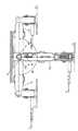
图4为从图1中装置支承臂的底面侧观察到的剖视图。Fig. 4 is a cross-sectional view viewed from the bottom surface side of the supporting arm of the device in Fig. 1 .

图5为从图1中装置支承臂的右侧观察到的剖视图。Fig. 5 is a sectional view viewed from the right side of the support arm of the device in Fig. 1 .

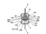
图6为图1的装置支承臂的、特别是在中间臂处剖视的从正面侧观察到的剖视图。FIG. 6 is a cross-sectional view from the front side of the device support arm of FIG. 1 , in particular at the middle arm.

图7为在图1的装置支承臂中采用的可动侧定位导引件、杆、推压部件、锁定部等的立体图。7 is a perspective view of a movable-side positioning guide, a lever, a pressing member, a locking portion, and the like employed in the device supporting arm of FIG. 1 .

图8显示了图1的装置支承臂的动作,是表示相对于基端侧臂使中间臂朝左右方向或上下方向转动来调节臂整体的左右方向或上下方向的角度的状态的图。FIG. 8 shows the movement of the device support arm in FIG. 1 , and is a diagram showing a state in which the angle of the entire arm in the left-right direction or vertical direction is adjusted by rotating the intermediate arm in the left-right direction or vertical direction with respect to the base-end side arm.

图9显示了图1的装置支承臂的动作,是表示相对于中间臂使前端侧臂朝左右方向或上下方向转动来调节基座板的左右方向或上下方向的角度的状态的图。9 shows the movement of the device support arm in FIG. 1 , and is a diagram showing a state in which the angle of the base plate is adjusted in the left-right direction or vertical direction by rotating the front-end side arm in the left-right direction or vertical direction relative to the intermediate arm.

图10显示了图1的装置支承臂的动作,是表示相对于前端侧臂使基座板背面的安装托架朝上下方向或左右方向转动来调节基座板的上下方向或左右方向的角度的状态的图。Fig. 10 shows the action of the device support arm in Fig. 1, which shows the angle of the up-down direction or left-right direction of the base plate by turning the mounting bracket on the back of the base plate in the up-down direction or left-right direction relative to the front end side arm. state diagram.

图11显示了图1的装置支承臂的动作,是表示相对于基座板背面的安装托架使基座板绕轴转动来调节基座板的转动角度的状态的图。FIG. 11 shows the movement of the device support arm of FIG. 1 , and is a view showing a state in which the base plate is pivoted with respect to the mounting bracket on the back surface of the base plate to adjust the rotation angle of the base plate.

(符号说明)(Symbol Description)

1监视器臂(装置支承臂)1 monitor arm (device support arm)

11基端侧臂11 base side arm

110螺纹孔110 threaded hole

12中间臂12 middle arm

121上表面121 upper surface

122下表面122 lower surface

123侧面123 side

124狭缝124 slits

125狭缝125 slits

126轴贯通孔126 shaft through holes

127线夹127 wire clamp

13前端侧臂13 front side arm

130轴贯通孔130 shaft through hole

131扇形平板(轴承部)131 fan-shaped flat plate (bearing part)

14固定底座14 fixed base

140螺钉贯通孔140 screw through hole

141螺钉贯通孔141 screw through hole

15基座板(基座)15 base plate (pedestal)

151凹部151 concave

152螺栓贯通孔152 bolt through hole

153螺栓(轴)153 bolt (shaft)

154螺母154 Nut

16安装托架16 mounting brackets

160安装孔160 mounting holes

161前表面161 front surface

162侧面162 side

163轴贯通孔163 shaft through hole

164轴承部164 Bearing Department

165衬套165 Bushing

166扭力螺旋弹簧166 torsion coil spring

168垫圈168 washer

169平垫圈169 flat washer

170碟形弹簧垫圈170 disc spring washer

171销(轴)171 pin (shaft)

2铰链装置2 hinges

21轴承21 bearing

210轴贯通孔210 shaft through hole

212轴212 axis

22轴承22 bearings

220轴贯通孔220 shaft through hole

221轴承部221 Bearing Department

222轴222 axis

23轴承23 bearings

230轴贯通孔230 shaft through hole

24第一端支承部24 first end support part

241框架241 frame

25第二端支承部25 second end support

250贯通孔250 through holes

26垫圈26 washers

27碟形弹簧垫圈27 disc spring washers

3固定侧定位导引件3Fixed side positioning guide

301槽301 slot

4可动侧定位导引件4 Movable side positioning guides

401爪401 claws

4F前方的可动侧定位导引件Movable side positioning guide in front of 4F

4R后方的可动侧定位导引件Movable side positioning guides at the rear of the 4R

41上表面(下表面)41 upper surface (lower surface)

411卡定凸起411 locking protrusion

42下表面(上表面)42 lower surface (upper surface)

43后端面(前端面)43 rear end face (front face)

44前端面(后端面)44 front face (rear face)

45侧面45 sides

450开口450 openings

451轴贯通部451 shaft through part

452推压部件贯通部452 Push part penetration part

453被推压部453 pushed part

454锁定槽454 locking slot

455切槽455 Grooving

456突状部456 protrusion

51推压部件51 pushing parts

510滚柱510 roller

511滚轴511 Roller

52锁定部52 locking department

53螺旋弹簧53 coil spring

6杆6 strokes

61杆主体61 rod body

62杆基部62 base

621轴贯穿孔621 shaft through hole

622推压部件贯穿孔622 push part through hole

63动作销63 action pins

7轴7 axis

8锁定装置8 locking device

81锁定槽(或锁定孔)81 locking groove (or locking hole)

82导引孔82 guide holes

83锁定销83 locking pin

831销831 pin

832凸缘832 flange

833手柄833 handle

84螺旋弹簧84 coil spring

85销壳体85 pin housing

850销导引件850 pin guide

851销贯通部851 pin through part

852销贯通部852 pin through part

853连接部853 connection part

854固定部854 fixed part

9螺旋式止动件9 screw stop

90螺纹孔90 threaded hole

91止动件主体91 stop body

911螺纹轴911 threaded shaft

912接触部件912 contact parts

913旋钮913 Knob

具体实施方式Detailed ways

下面,利用附图对用于实施本发明的方式进行说明。在该实施方式中,将本发明的装置支承臂特别例示为在轿车或货车等车辆内用于设置监视器的监视器臂,在以下的说明中,将该机器支承臂称为监视器臂。Hereinafter, modes for implementing the present invention will be described with reference to the drawings. In this embodiment, the device support arm of the present invention is specifically exemplified as a monitor arm for installing a monitor in a vehicle such as a car or a truck, and in the following description, this machine support arm is referred to as a monitor arm.

如图1以及图2所示,监视器臂1设有多个臂11、12、13。臂11、12、13通过铰接装置2、2彼此可沿水平方向(左右方向)或垂直方向(上下方向)转动地连接,并且,臂11、12、13之间以可保持任意转动角度的方式连接。此外,在基端侧臂11上设有固定底座14,该固定底座用于将所有的臂11、12、13全部支承固定在作为安装端的车辆驾驶室内的仪表板等上,在前端侧臂13上设有用于安装监视器的基座板15。As shown in FIGS. 1 and 2 , the monitor arm 1 includes a plurality ofarms 11 , 12 , and 13 . Thearms 11, 12, 13 are rotatably connected to each other through thehinge device 2, 2 in the horizontal direction (left-right direction) or vertical direction (up-down direction), and thearms 11, 12, 13 can maintain any rotation angle. connect. In addition, on the baseend side arm 11, a fixedbase 14 is provided for supporting and fixing all thearms 11, 12, 13 on the instrument panel or the like in the vehicle cab as the installation end, and on the front end side arm 13 Abase plate 15 for installing a monitor is provided on the top.

对于该实施方式的监视器臂1而言,多个臂11、12、13由基端侧臂11、中间臂12以及前端侧臂13这3个臂构成。中间臂12最长,基端侧臂11最短,前端侧臂13比中间臂12短,比基端侧臂11长。In the monitor arm 1 of this embodiment, the plurality ofarms 11 , 12 , and 13 are constituted by three arms of the baseend side arm 11 , theintermediate arm 12 , and the frontend side arm 13 . Themiddle arm 12 is the longest, the baseend side arm 11 is the shortest, and the frontend side arm 13 is shorter than themiddle arm 12 and longer than the baseend side arm 11 .

如图1以及图2所示,中间臂12为整体由铝板制成的具有规定长度的较长大致方筒状,并具有上表面121、下表面122以及两个侧面123、123。另外,使构成与前端侧臂13以及基端侧臂11连接的连接端的前后端面分别开口,同时,形成有轴承22、22。在该实施方式中,中间臂12是使上下一分为二的形成大致倒U字形截面以及U字形截面的上部侧的臂部件以及下部侧的臂部件结合为一体二形成的,并构成中空的大致方筒形。形成为细长矩形的上下各个表面121、122的前后两个边缘部分别沿前后方向、以大致圆弧状从两个侧面123、123的前后两个边缘部伸出,并且,在其中心贯穿形成轴贯通孔220、220,形成后面所述的前端侧臂13以及基端侧臂11的轴承23,21可以嵌合的一对轴承部221、221、221、221。另外,在上表面12的后方中央部,沿前后方向形成有用于使后面所述的后侧杆6通过的狭缝124;在下表面122的前方中央部,沿前后方向形成有用于使后面所述的前侧杆6通过的狭缝125。两个侧面123、123分别以细长的矩形形状形成,在各个侧面123上,在与设置于上表面121以及下表面122上的各个狭缝124、125的前后方向中央对应的规定位置处,分别形成有轴贯通孔126、126。用于枢轴支承后面所述的杆6的轴7贯通设置在各个侧面123上的各个轴贯通孔126。另外,在该中间臂12的上表面121、下表面122以及两个侧面123、123上,在适当的位置处安装有用于约束从监视器伸出的各种电缆的线夹127。As shown in FIG. 1 and FIG. 2 , theintermediate arm 12 is made of an aluminum plate and has a long and substantially square tube shape with a predetermined length, and has anupper surface 121 , alower surface 122 and twoside surfaces 123 , 123 . In addition, the front and rear end surfaces constituting the connecting ends to thedistal side arm 13 and theproximal side arm 11 are respectively opened, andbearings 22 , 22 are formed. In this embodiment, theintermediate arm 12 is formed by combining an upper arm member and an arm member on the lower side which are divided into two and form a substantially inverted U-shaped cross-section and a U-shaped cross-section, and constitute a hollow body. Roughly square cylindrical. The front and rear edges of each of the upper andlower surfaces 121, 122 formed in an elongated rectangle protrude from the front and rear edges of the twoside surfaces 123, 123 in a substantially arc shape along the front and rear directions, and penetrate through the center thereof. Shaft throughholes 220 , 220 are formed, and a pair of bearingportions 221 , 221 , 221 , 221 to whichbearings 23 , 21 of thedistal side arm 13 and theproximal side arm 11 described later are fitted are formed. In addition, in the rear central part of theupper surface 12, aslit 124 for passing therear side rod 6 described later is formed along the front-rear direction; Theslit 125 through which thefront side bar 6 passes. The twoside surfaces 123, 123 are formed in an elongated rectangular shape, and on each of the side surfaces 123, at predetermined positions corresponding to the centers in the front-rear direction of therespective slits 124, 125 provided on theupper surface 121 and thelower surface 122, Shaft throughholes 126, 126 are formed respectively. A shaft 7 for pivotally supporting alever 6 described later passes through each shaft throughhole 126 provided on eachside surface 123 . In addition, on theupper surface 121 , thelower surface 122 and the twoside surfaces 123 , 123 of theintermediate arm 12 , wire clips 127 for restraining various cables protruding from the monitor are installed at appropriate positions.

如图4以及图5所示,在该中间臂12的内部,在各个轴贯通孔126、126、126、126的前后规定位置处,分别设有支承后面所述的前后各个可动侧定位导引件4、4中一个的端部侧的第一端支承部24、24以及支承其相反侧的端部侧的第二端支承部25,25。在该实施方式中,第一端支承部24、24形成整体可以嵌合在中间臂12内的框架结构,在其大致中央具有将可动侧定位导引件4、4的第一端部保持成可滑动的框架241、241。各个第一端支承部24、24在两个侧面123、123之间的规定位置处接近一对轴承部221、221并通过螺钉安装。第二端支承部25、25形成整体可以嵌合在中间臂12内的板状,在其大致中央具有供可动侧定位导引件4、4的第二端部贯通并将其支承成可滑动的贯通孔250、250。通过螺钉,将各个第二端支承部25、25安装在两个侧面123、123之间的前后方向中央侧的规定位置处。As shown in FIGS. 4 and 5 , inside theintermediate arm 12 , at predetermined front and rear positions of the respective shaft throughholes 126 , 126 , 126 , 126 , there are respectively provided front and rear positioning guides for supporting the movable sides described later. The firstend support portions 24, 24 on the end side of one of thelead members 4, 4 and the secondend support portions 25, 25 on the opposite end side. In this embodiment, the firstend support parts 24, 24 form a frame structure that can be fitted into theintermediate arm 12 as a whole, and have a frame structure that holds the first ends of the movable side positioning guides 4, 4 in the approximate center. into a slidable frame 241,241. Each firstend support portion 24, 24 approaches a pair of bearingportions 221, 221 at a prescribed position between both side surfaces 123, 123 and is mounted by screws. The secondend supporting parts 25, 25 form a plate shape that can be fitted into themiddle arm 12 as a whole, and have a second end portion in the approximate center of which the movableside positioning guide 4, 4 penetrates and supports it to be rotatable. Sliding throughholes 250 , 250 . The respective secondend support portions 25 , 25 are attached to predetermined positions on the center side in the front-rear direction between the twoside surfaces 123 , 123 with screws.

如图1以及图2所示,基端侧臂11为整体由铝合金制成的具有规定长度的块状。在形成与中间臂12连接的连接端的前端部形成有大致筒状的轴承21,在其外周面上形成有由沿周向设置的多个槽或孔构成的固定侧定位导引件3。在该实施方式中,基端侧臂11由前端部为半圆筒状而后端部为方筒状的具有复合形状的块体构成。半圆筒状的前端部以可以嵌入中间臂12的后端部的一对轴承部221、221之间的尺寸形成,在其轴芯贯通形成有轴贯通孔210,从而形成半圆筒状的轴承21。并且,在该轴承21的外周面,如图2以及图4所示,沿周向形成有多个纵向槽301,从而形成齿轮状。该齿轮形状形成了固定侧定位导引件3。基端侧臂11的后端部为形成在该轴承21的后方延伸线上的方筒状部分,在后面形成有大致矩形的凹状部,在其四个角处设置有固定底座装配用的螺钉孔110。As shown in FIGS. 1 and 2 , the base-end side arm 11 has a block shape with a predetermined length and is entirely made of aluminum alloy. A substantiallycylindrical bearing 21 is formed at a front end portion forming a connection end to theintermediate arm 12, and a fixed-side positioning guide 3 composed of a plurality of grooves or holes arranged in the circumferential direction is formed on its outer peripheral surface. In this embodiment, the baseend side arm 11 is constituted by a block having a complex shape with a semi-cylindrical front end and a square cylindrical rear end. The semi-cylindrical front end is formed in a size that can fit between a pair of bearingparts 221, 221 at the rear end of theintermediate arm 12, and a shaft throughhole 210 is formed through the shaft core to form asemi-cylindrical bearing 21. . Further, on the outer peripheral surface of thebearing 21, as shown in FIGS. 2 and 4 , a plurality oflongitudinal grooves 301 are formed in the circumferential direction to form a gear shape. This gear shape forms the fixed-side positioning guide 3 . The rear end portion of the baseend side arm 11 is a square cylindrical portion formed on the rear extension line of thebearing 21, and a substantially rectangular concave portion is formed on the rear surface, and screws for fixing the base assembly are provided at the four corners.Hole 110.

如图1以及图2所示,前端侧臂13为整体由铝合金制成的具有规定长度的块状。在构成与中间臂12连接的连接端的后端部形成有大致筒状的轴承23,在其外周面上形成有由沿周向设置的多个槽或孔构成的固定侧定位导引件3。在该实施方式中,前端侧臂13由后端部为半圆筒状而在前端部具有一对扇形平板的复合形状的块体构成。大致半圆筒状的后端部与基端侧臂11的前端部一样,以可以嵌入中间臂12的前端部的一对轴承部221、221之间的尺寸形成,在其轴芯贯通形成有轴贯通孔230,从而形成半圆筒状的轴承23。并且,在该轴承23的外周面,如图2以及图4所示,沿周向形成有多个纵向槽301,从而形成齿轮状。该齿轮形状形成了固定侧定位导引件3。在形成前端部的扇形的各块平板131的中央,贯通形成有轴贯通孔130、130。一对平板131、131之间具有一定间隔并从轴承23的外周面的前部向前方伸出,从而形成用于装配基座板15的一对轴承部131、131。另外,在形成这对轴承部的平板131、131中的两块平板或一块平板的轴贯通孔130的周围,沿圆弧状的边缘部,以大致圆弧状并列形成多个小槽或孔。这些槽或孔形成后面所述的锁定装置8的锁定槽(或锁定孔)81。As shown in FIGS. 1 and 2 , the frontend side arm 13 is in the shape of a block with a predetermined length and is entirely made of aluminum alloy. A substantiallycylindrical bearing 23 is formed at a rear end constituting a connection end to theintermediate arm 12, and a fixed-side positioning guide 3 composed of a plurality of grooves or holes arranged in the circumferential direction is formed on its outer peripheral surface. In this embodiment, the frontend side arm 13 is constituted by a compound-shaped block having a semicylindrical rear end and a pair of fan-shaped flat plates at the front end. The substantially semi-cylindrical rear end is formed in the same size as the front end of theproximal side arm 11 to fit between a pair ofbearings 221, 221 at the front end of theintermediate arm 12, and a shaft is formed through the center of the shaft. The throughhole 230 forms asemi-cylindrical bearing 23 . Further, on the outer peripheral surface of thebearing 23, as shown in FIGS. 2 and 4 , a plurality oflongitudinal grooves 301 are formed in the circumferential direction to form a gear shape. This gear shape forms the fixed-side positioning guide 3 . Shaft through-holes 130 , 130 are penetratingly formed in the center of each fan-shapedflat plate 131 forming the tip portion. The pair offlat plates 131 , 131 protrude forward from the front portion of the outer peripheral surface of the bearing 23 with a certain distance therebetween, thereby forming a pair of bearingportions 131 , 131 for mounting thebase plate 15 . In addition, around the axis throughhole 130 of two or one of theflat plates 131, 131 forming the pair of bearing portions, a plurality of small grooves or holes are formed in parallel in a substantially arc shape along the arc-shaped edge. . These grooves or holes form locking grooves (or locking holes) 81 of thelocking device 8 described later.

如图4以及图5所示,铰接装置2、2分别设有:大致筒形的轴承21、23,这些轴承形成在邻接的臂11/12以及12/13中的一方臂11、13的连接端上;形成在另一方臂12、12的连接端上的可相对转动地与轴承21、23连接的轴承22、22;在臂11以及12的轴承21、22之间以及在臂12、13的轴承22、23之间贯通的轴212、222;设置在轴承21、23的外周面上的固定侧定位导引件3;设置在另一方臂12上并相对于固定侧定位导引件3可进退地设置的可动侧定位导引件4;杆6,其具有可以向固定侧定位导引件3推压可动侧定位导引件4的推压部件51;以及锁定部52,其在相对于固定侧定位导引件3推压可动侧定位导引件4的状态下,与推压部件卡合以限制杆6的运动。可动侧定位导引件4通过弹簧装置,在常态下被拉离固定侧定位导引件3,并在与固定侧定位导引件3相对的端部上具有可以与槽301卡合的爪401。杆6以及锁定部52与可动侧定位导引件4一样,可转动地设置在中间臂12上。As shown in Fig. 4 and Fig. 5, thehinge devices 2, 2 are respectively provided with: substantiallycylindrical bearings 21, 23, and these bearings form the connection of onearm 11, 13 in theadjacent arms 11/12 and 12/13. On the end; Formed on the connecting end of theother side arm 12,12 Thebearing 22,22 that is connected with thebearing 21,23 in a relatively rotatable manner; Between thebearing 21,22 of thearm 11 and 12 and in thearm 12,13 Theshafts 212, 222 passing through between thebearings 22, 23; the fixedside positioning guide 3 arranged on the outer peripheral surface of thebearing 21, 23; the fixedside positioning guide 3 arranged on theother side arm 12 and relative to the fixed side The movable-side positioning guide 4 that can be set forward and backward; thelever 6 that has a pressingmember 51 that can push the movable-side positioning guide 4 toward the fixed-side positioning guide 3; and the lockingportion 52 that In a state where the movable-side positioning guide 4 is pressed against the fixed-side positioning guide 3 , it engages with the pressing member to restrict the movement of therod 6 . The movable-side positioning guide 4 is pulled away from the fixed-side positioning guide 3 under normal conditions through a spring device, and has a pawl on the end opposite to the fixed-side positioning guide 3 that can engage with thegroove 301 401. Thelever 6 and thelock portion 52 are rotatably provided on theintermediate arm 12 like the movable-side positioning guide 4 .

在该实施方式中,如已描述的那样,中间臂12的前后端的各个轴承22由具有轴贯通孔220的一对轴承部221、221构成,基端侧臂11以及前端臂13的各个轴承21、23采用可以嵌入中间臂12的一对轴承部221、221之间的方式、以大致半圆筒形形成,固定侧定位导引件3、3在各个轴承21、23的外周面上形成为周向的多个槽301。在该实施方式中,槽301以10°的角度间隔形成在各个轴承21、23的外周面上。这些基端侧臂11以及前端侧臂13的各个轴承21、23嵌入中间臂12的前后端的各一对轴承部221、221之间,在上下两侧与各个轴贯通孔210、230同芯地设置有垫圈26、26。另外,在中间臂12的前后端的一对轴承部221、221的两侧,与轴贯通孔220、220同芯地依次设置有垫圈26、26以及碟形弹簧垫圈27、27,使轴212、222贯通轴贯通孔220、220和轴贯通孔210以及轴贯通孔220、220和轴贯通孔230。这样,基端侧臂11以及前端侧臂13的各个轴承21、23通过轴212、222连接在中间臂12的前后端的各一对轴承部221、221之间,设置在这些轴承21、23中的固定侧定位导引件3、3与中间臂的前后端部的开口相对设置。In this embodiment, as already described, each bearing 22 at the front and rear ends of theintermediate arm 12 is constituted by a pair of bearingportions 221, 221 having a shaft throughhole 220, and each bearing 21 of the proximalend side arm 11 and thedistal end arm 13 , 23 are formed in a substantially semi-cylindrical shape so as to fit between a pair of bearingparts 221, 221 of theintermediate arm 12, and fixed-side positioning guides 3, 3 are formed on the outer peripheral surface of each bearing 21, 23 as a circumferential A plurality ofgrooves 301 in the direction. In this embodiment,grooves 301 are formed on the outer peripheral surfaces of therespective bearings 21 , 23 at angular intervals of 10°. Therespective bearings 21, 23 of theproximal side arm 11 and thedistal side arm 13 are fitted between the respective pairs of bearingportions 221, 221 at the front and rear ends of theintermediate arm 12, and are concentric with the respective shaft throughholes 210, 230 on the upper and lower sides.Washers 26, 26 are provided. In addition, on both sides of the pair of bearingportions 221, 221 at the front and rear ends of theintermediate arm 12,washers 26, 26 andBelleville spring washers 27, 27 are sequentially provided concentrically with the shaft throughholes 220, 220, so that theshaft 212, 222 passes through the shaft throughholes 220 , 220 and the shaft throughhole 210 , and the shaft throughholes 220 , 220 and the shaft throughhole 230 . In this way, therespective bearings 21, 23 of the baseend side arm 11 and the frontend side arm 13 are connected between the respective pairs of bearingportions 221, 221 at the front and rear ends of theintermediate arm 12 throughshafts 212, 222, and are arranged in thesebearings 21, 23. The fixed side positioning guides 3, 3 are arranged opposite to the openings of the front and rear ends of the intermediate arm.

另一方面,在中间臂12内,如已经描述的那样,设置有支承可动侧定位导引件4的一个端部侧的第一端支承部24以及支承其相反侧的端部侧的第二端支承部25。另外,分别在这些第一端支承部24和第二端支承部25上,各安装有一个可动侧定位导引件4。所述可动侧定位导引件4利用铝合金形成在上部或下部具有凹凸形状的横向较长的大致矩形板状。On the other hand, in theintermediate arm 12, as already described, there are provided the firstend supporting portion 24 supporting one end side of the movableside positioning guide 4 and the second end supporting portion supporting the opposite end side thereof. Two-end supporting portion 25 . In addition, one movableside positioning guide 4 is attached to each of these firstend support portions 24 and secondend support portions 25 . The movableside positioning guide 4 is made of an aluminum alloy and is formed in the shape of a substantially rectangular plate having a concave-convex shape on the upper or lower portion in the lateral direction.

对于后方的可动侧定位导引件4(4R)而言,如图5以及图7所示,在上表面41的较中央稍靠前端侧,形成有卡定凸起411,下表面42以平面状形成。在本实施方式中,在后端面43(与固定侧定位导引件3相对的端面)形成有3个可以与固定侧定位导引件3的槽301卡合的沿纵向延伸的爪401。前端面44以平面状形成。左右两个侧面45、45以平面状形成,以贯穿这两个侧面45、45的方式,形成切槽455和具有复合形状的开口450。从前端侧直至大致中央附近,切槽455以横向的大致U字形设置,并且,在前端侧设置开放端,向中央附近设置封闭端,从而形成突状部456。在该突状部456上装有螺旋弹簧53。开口450形成从可动侧定位导引件4的前端面44侧向后端面43侧延伸的长孔形状。在该开口450的前方,设置用于支承可动侧定位导引件4的轴7的轴贯通部451,在后方设置供推压部件51贯通的推压部件贯通部452。推压部件贯通部452具有通过推压部件51推压的被推压部453和在该被推压部453的下方终端侧形成作为推压部件51的锁定部52的锁定槽454。被推压部453承受贯通的推压部件51的推压力,并推压可动侧定位导引件4向固定侧定位导引件3移动。使推压部件51嵌入锁定槽454中并对其周围进行约束固定。For the movable side positioning guide 4 (4R) at the rear, as shown in FIGS. flat form. In this embodiment, threeclaws 401 extending longitudinally that can engage with thegrooves 301 of the fixedside positioning guide 3 are formed on the rear end surface 43 (the end surface opposite to the fixed side positioning guide 3 ). Thefront end surface 44 is formed in a planar shape. Both left and right side surfaces 45 , 45 are formed in a planar shape, and anotch 455 and anopening 450 having a complex shape are formed so as to pass through the twoside surfaces 45 , 45 . Thenotch 455 is provided in a substantially U-shape in the transverse direction from the front end to the vicinity of the center, and theprotrusion 456 is formed by providing an open end on the front end and a closed end near the center. Thecoil spring 53 is attached to the protrudingportion 456 . Theopening 450 is in the shape of a long hole extending from thefront end surface 44 side to therear end surface 43 side of the movableside positioning guide 4 . In front of theopening 450, ashaft penetration portion 451 for supporting the shaft 7 of the movableside positioning guide 4 is provided, and a pressingmember penetration portion 452 through which the pressingmember 51 penetrates is provided behind. The pushingmember penetration portion 452 has a pushedportion 453 pushed by the pushingmember 51 and a lockinggroove 454 formed as the lockingportion 52 of the pushingmember 51 on the lower terminal side of the pushedportion 453 . The pressedportion 453 receives the pressing force of the pressingmember 51 penetrating therethrough, and presses the movable-side positioning guide 4 to move toward the fixed-side positioning guide 3 . The pushingmember 51 is fitted into the lockinggroove 454 and its periphery is restrained and fixed.

推压部件51与杆6一起安装到该可动侧定位导引件4中。推压部件51由滚柱510构成。杆6一体地设有杆主体61、形成在杆主体61的枢轴支承侧端部上的一对杆基部62、62。一对杆基部62、62可并列设置地形成在可动侧定位导引件4R的开口450的两侧,各个杆基部62具有与轴贯通部451和推压部件贯通部452对应的轴贯穿孔621以及推压部件贯穿孔622。在该实施方式中,杆6是采用两个杆基材并接合杆主体部分而形成的,其中,所述杆基材具有细长的杆主体部分和上部为矩形而下部为沿横向使大小两个圆合并而形成复合形状的杆基部部分。并且,在一对杆基部62、62之间,使动作销63在上部穿过。这样,如图6所示,杆6的一对杆基部62、62从上方跨设在可动侧定位导引件4R的开口450的两侧,在推压部件贯穿孔622、622之间,借助穿过可动侧定位导引件4R的推压部件贯通部452的滚轴511安装有推压部件51的滚柱510,从而将推压部件51与杆6一起装配在可动侧定位导引件4R上。The urgingmember 51 is fitted into this movable-side positioning guide 4 together with therod 6 . The pressingmember 51 is composed ofrollers 510 . Thelever 6 is integrally provided with a levermain body 61 , a pair oflever bases 62 , 62 formed on the pivot support side end portion of the levermain body 61 . A pair oflever bases 62 , 62 are formed on both sides of theopening 450 of the movableside positioning guide 4R so that they can be arranged side by side, and eachlever base 62 has a shaft penetration hole corresponding to theshaft penetration portion 451 and the pressingmember penetration portion 452 . 621 and the pushing member throughhole 622. In this embodiment, therod 6 is formed using two rod base materials having an elongated rod body part and an upper part of rectangular shape and a lower part of two sizes transversely and joined to the rod body part. The two circles merge to form the base portion of the compound shape. And between a pair oflever base part 62,62, theoperation pin 63 is passed in the upper part. In this way, as shown in FIG. 6, a pair ofrod bases 62, 62 of therod 6 are straddled from above on both sides of theopening 450 of the movableside positioning guide 4R, between the pressing member throughholes 622, 622, Theroller 510 of the pressingmember 51 is attached to theroller 510 of the pressingmember 51 through theroller 511 passing through the pressingmember penetration portion 452 of the movableside positioning guide 4R, thereby assembling the pressingmember 51 together with therod 6 on the movable side positioning guide.Primer 4R on.

对于前方的可动侧定位导引件4F而言,如图5所示,虽然具有与后方的可动侧定位导引件4R相同的形状、结构,但是,由于其是以相对于后方的可动侧定位导引件4R反转180°的方向安装的,因此,各个部分的方向与后方的可动侧定位导引件4R正好相反。即,在下表面41的中央稍靠后端侧形成卡定凸起411,上表面42以平面状形成。在该实施方式中,在前端面43(与固定侧定位导引件3相对的端面)上,形成有3个可以与固定侧定位导引件3的槽301卡合的纵向延伸的爪401。后端面44以平面状形成。左右两个侧面45、45以平面状形成,在这两个侧面45、45之间形成有切槽455和复合形状的开口450,贯通这两个侧面45、45形成切槽455和开口450。切槽455从后端侧直至大致中央附近,以横向的大致U字形设置,并且,在后端侧设置开放端,向中央附近设置封闭端,从而形成突状部456。在该突状部456上装有螺旋弹簧53。开口450形成从可动侧定位导引件4的后端面44侧向前端面43侧延伸的长孔形状。在该开口450的后方,设置有用于支承可动侧定位导引件4的轴7的轴贯通部451,在前方设置有供推压部件51穿过的推压部件贯通部452。推压部件贯通部452具有通过推压部件51推压的被推压部453和在该被推压部453的上方终端侧形成作为推压部件51的锁定部52的锁定槽454。被推压部453承受贯通的推压部件51的推压力,并推压可动侧定位导引件4向固定侧定位导引件3移动。使推压部件嵌入锁定槽454中并对其周围进行约束固定。As for the movableside positioning guide 4F in the front, as shown in FIG. The movingside positioning guide 4R is installed in the direction reversed by 180°, so the direction of each part is just opposite to the rear movingside positioning guide 4R. That is, the lockingprotrusion 411 is formed in the center of thelower surface 41 slightly toward the rear end, and theupper surface 42 is formed in a planar shape. In this embodiment, three vertically extendingpawls 401 that can engage with thegrooves 301 of the fixed-side positioning guide 3 are formed on the front end surface 43 (the end surface opposite to the fixed-side positioning guide 3 ). Therear end surface 44 is formed in a planar shape. The left andright sides 45 , 45 are formed in a planar shape, and anotch 455 and a compound-shapedopening 450 are formed between the twosides 45 , 45 , and thenotch 455 and theopening 450 are formed through the twosides 45 , 45 . Thenotch 455 is formed in a substantially U-shape in the transverse direction from the rear end side to the vicinity of the center, and has an open end at the rear end side and a closed end near the center, thereby forming a protrudingportion 456 . Thecoil spring 53 is attached to the protrudingportion 456 . Theopening 450 is in the shape of a long hole extending from therear end surface 44 side to thefront end surface 43 side of the movableside positioning guide 4 . Behind theopening 450, ashaft penetration portion 451 for supporting the shaft 7 of the movableside positioning guide 4 is provided, and a pressingmember penetration portion 452 through which the pressingmember 51 passes is provided in the front. The pushingmember penetration portion 452 has a pushedportion 453 pushed by the pushingmember 51 and a lockinggroove 454 formed as the lockingportion 52 of the pushingmember 51 on the upper terminal side of the pushedportion 453 . The pressedportion 453 receives the pressing force of the pressingmember 51 penetrating therethrough, and presses the movable-side positioning guide 4 to move toward the fixed-side positioning guide 3 . The pressing member is fitted into thelock groove 454 and its periphery is restrained and fixed.

推压部件51与杆6一起安装在该可动侧定位导引件4上。推压部件51由滚柱510构成。杆6一体地设有杆主体61、形成在杆主体61的枢轴支承侧端部上的一对杆基部62、62。一对杆基部62、62可并列设置地形成在可动侧定位导引件4F的开口450的两侧,并具有与轴贯通部451和推压部件贯通部452对应的轴贯穿孔621以及推压部件贯穿孔622。在该实施方式中,杆6是采用两个杆基材并使杆主体部分结合且通过螺钉卡定而成的,其中,所述杆基材具有细长的杆主体部分和下部为矩形而上部为沿横向使大小两个圆合并而形成复合形状的杆基部部分。并且,在各对杆基部62、62之间,使动作销63在下部穿过。这样,对于杆6而言,一对杆基部62、62从下方跨设在可动侧定位导引件4F的开口450的两侧,在推压部件贯穿孔622、622之间,借助穿过可动侧定位导引件4F的推压部件贯通部452的滚轴511安装推压部件51的滚柱510,从而将推压部件51与杆6一起装配在可动侧定位导引件4F上。The pressingmember 51 is attached to the movable-side positioning guide 4 together with therod 6 . The pressingmember 51 is composed ofrollers 510 . Thelever 6 is integrally provided with a levermain body 61 , a pair oflever bases 62 , 62 formed on the pivot support side end portion of the levermain body 61 . A pair ofrod bases 62, 62 are formed on both sides of theopening 450 of the movable-side positioning guide 4F so that they can be arranged side by side, and have a shaft throughhole 621 corresponding to the shaft throughportion 451 and the push member throughportion 452 and a pushing member. The pressing member passes through thehole 622 . In this embodiment, therod 6 is formed by using two rod base materials with a long and thin rod body part and a rectangular lower part and an upper part by combining the rod main parts and locking them with screws. A rod base portion of a compound shape formed by merging two large and small circles in the transverse direction. And between each pair oflever base parts 62 and 62, theoperation pin 63 is passed in the lower part. In this way, for therod 6, a pair ofrod bases 62, 62 are straddled from below on both sides of theopening 450 of the movableside positioning guide 4F, between the pressing member throughholes 622, 622, by passing through Theroller 510 of the pressingmember 51 is attached to theroller 511 of the pressingmember penetration portion 452 of the movableside positioning guide 4F, and the pressingmember 51 is mounted on the movableside positioning guide 4F together with therod 6 .

这样,可动侧定位导引件4R、4F分别在中间臂12内,使具有爪401的第二端部贯通并支承在第一端支承部24的框架241上,使另一侧的第二端部贯通并支承在第二端支承部25的贯通孔250中。装配于在第二端部侧切口形成的突状部456上的螺旋弹簧53在切槽455的端部与第二端支承部25之间被压缩,朝将各个可动侧定位导引件4拉离各个固定侧定位导引件3的方向,进行拉动施力。另外,在这些可动侧定位导引件4R、4F装配的同时,后方的杆6的杆主体61从中间臂12的内部,通过上表面的狭缝124向外部伸出,前方的杆6的杆主体61从中间臂12的内部,通过下表面的狭缝125向外部伸出。另外,使轴7在中间臂12的两个侧面123、123的轴贯通孔126、126之间、一对杆基部62、62的轴贯穿孔621、621之间以及可动侧定位导引件4的轴贯通部451穿过,杆6可在可动侧定位导引件4的第一端部与第二端部之间倾斜地被枢轴支承在中间臂12上。这样,各根杆6和各个推压部件51与各个可动侧定位导引件4动作地连接。若使杆6向固定侧定位导引件3的方向倾斜,则在可动侧定位导引件4的推压部件贯通部452内,推压部件51推压被推压部453以嵌入锁定槽454内,从而将可动侧定位导引件4压接在固定侧定位导引件3上并保持这种状态。另一方面,若使杆6向相反方向倾斜,则杆6的动作销63和可动侧定位导引件4的卡定凸起411结合,以拉回可动侧定位导引件4,从而将其拉离固定侧定位导引件3。In this way, the movable side positioning guides 4R, 4F are respectively in theintermediate arm 12, and the second end portion having theclaw 401 is penetrated and supported on theframe 241 of the firstend support portion 24, so that the second end portion on the other side The end portion penetrates and is supported in the throughhole 250 of the secondend support portion 25 . Thecoil spring 53 fitted on the protrudingportion 456 formed in the second end side notch is compressed between the end of thenotch 455 and the secondend support portion 25, toward positioning eachmovable side guide 4 Pull away from the direction of each fixed-side positioning guide 3 to apply force. In addition, when these movable side positioning guides 4R, 4F are assembled, the rodmain body 61 of therear rod 6 protrudes from the inside of theintermediate arm 12 to the outside through theslit 124 on the upper surface, and therod body 61 of thefront rod 6 protrudes to the outside. The rodmain body 61 protrudes from the inside of theintermediate arm 12 to the outside through theslit 125 on the lower surface. In addition, the shaft 7 is positioned between the shaft throughholes 126, 126 of the twoside surfaces 123, 123 of theintermediate arm 12, between the shaft throughholes 621, 621 of the pair ofrod bases 62, 62, and between the movable side positioning guides. Theshaft penetration portion 451 of theguide 4 passes through, and therod 6 is pivotally supported on theintermediate arm 12 obliquely between the first end and the second end of the movableside positioning guide 4 . In this way, eachrod 6 and each pressingmember 51 are operatively connected to each movableside positioning guide 4 . When thelever 6 is tilted toward the fixed-side positioning guide 3, the pushingmember 51 pushes the pressedportion 453 in the pushingmember penetration portion 452 of the movable-side positioning guide 4 to fit into the locking groove. 454, so that the movable-side positioning guide 4 is crimped on the fixed-side positioning guide 3 and maintained in this state. On the other hand, if thelever 6 is tilted in the opposite direction, theaction pin 63 of thelever 6 is combined with the lockingprotrusion 411 of the movableside positioning guide 4 to pull back the movableside positioning guide 4, thereby Pull it away from the fixedside positioning guide 3.

如图4以及图5所示,固定底座14整体由钢材以大致矩形的板状形成,在与基端侧臂11后表面的各个螺纹孔110对应的四个角处设置有螺钉贯通孔140,在其周围还设有用于将固定底座14安装在车辆驾驶室内的多个螺钉贯通孔141。通过使螺钉从各个螺钉贯通孔140穿过并卡定在基端侧臂11的各个螺纹孔110中,从而将该固定底座14安装在基端侧臂11的后表面上。As shown in FIGS. 4 and 5 , the fixedbase 14 is generally formed of steel in a substantially rectangular plate shape, and screw throughholes 140 are provided at four corners corresponding to the threadedholes 110 on the rear surface of theproximal side arm 11 . A plurality of screw through-holes 141 for mounting the fixedbase 14 in the cab of the vehicle are also provided around it. The fixingbase 14 is attached to the rear surface of theproximal side arm 11 by passing screws through the respective screw throughholes 140 and locking them in the respective threadedholes 110 of theproximal side arm 11 .

如图3所示,基座板15为整体由钢材制成并具有规定尺寸的大致矩形平板,在其正面中央以向背面侧突出的方式形成有凹部151,并且,在其中心开设有螺栓贯通孔152。另外,如图4以及图5所示,在该基座板15的后表面上设有安装托架16。该安装托架16由钢材以断面コ字状形成,在前表面161上开设有用于安装基座板15的安装孔160。两个侧面162、162从前表面161的左右两侧向后方以大致梯形或大致三角形形状突出,并且,在各个突出端的大致中央开设有轴贯通孔163、163。两个侧面162、162以可以使前端侧臂13的前侧的一对轴承部131、131嵌合的间隔设置,从而形成一对轴承部164、164。在安装托架16的前表面161上,与安装孔160同芯地夹设有垫圈并重叠基座板15,在使这些安装孔160与基座板15的螺栓贯通孔152重合的状态下,在基座板15上,与螺栓贯通孔152同芯地依次设置有垫圈、碟形弹簧垫圈、平垫圈,使螺栓153从基座板15的前表面通过这些孔160、152,并将其拧接在位于安装托架16的前表面161的背面侧的螺母154中。这样,基座板15以螺栓153为转动中心可转动地并且通过由垫圈等产生的摩擦阻力作用可保持任意转动角度地安装在安装托架16的前表面161上。As shown in FIG. 3 , thebase plate 15 is a generally rectangular flat plate made of steel and has a predetermined size. Aconcave portion 151 is formed in the center of the front surface so as to protrude toward the back side, and a bolt penetrates through the center of thebase plate 15 .Hole 152. In addition, as shown in FIGS. 4 and 5 , anattachment bracket 16 is provided on the rear surface of thebase plate 15 . The mountingbracket 16 is formed of steel with a U-shaped cross section, and a mountinghole 160 for mounting thebase plate 15 is opened on thefront surface 161 . The twoside surfaces 162 , 162 protrude rearward from the left and right sides of thefront surface 161 in a substantially trapezoidal or substantially triangular shape, and shaft throughholes 163 , 163 are opened in substantially the center of each protruding end. The twoside surfaces 162 , 162 are provided at intervals at which the pair of bearingportions 131 , 131 on the front side of thefront end arm 13 can fit, thereby forming a pair of bearingportions 164 , 164 . On thefront surface 161 of the mountingbracket 16, a washer is interposed concentrically with the mountingholes 160 and thebase plate 15 is superimposed. On thebase plate 15, washers, Belleville spring washers, and flat washers are sequentially arranged concentrically with the bolt throughholes 152, and thebolts 153 are passed through theseholes 160, 152 from the front surface of thebase plate 15, and screwed. Received in thenut 154 located on the rear side of thefront surface 161 of the mountingbracket 16 . Thus, thebase plate 15 is mounted on thefront surface 161 of the mountingbracket 16 so as to be rotatable around thebolt 153 and to maintain an arbitrary rotation angle by the frictional resistance effect of the washer or the like.

之后,使该基座板15的安装托架16与前端侧壁13铰链连接。在这种实施方式中,在安装托架16的一对轴承部164、164之间设置前端侧壁13的一对轴承部131、131,使各个轴贯通孔163、163、130、130重合。在这种状态下,将圆筒状的衬套165设置在轴承部131、131的轴贯通孔130、130之间,并在该衬套165上,以规定方向卷绕安装扭力螺旋弹簧166。扭力螺旋弹簧166的一个卡定端卡定(固定)在安装托架16的前表面161的背面侧,另一卡定端卡定(固定)在前端侧臂13的前表面上。并且,在轴承部131、131的两侧,与轴贯通孔130、130同芯地配置垫圈168、168,在安装托架16的轴承部164、164的一侧,与轴贯通孔163同芯地依次配置平垫圈169、碟形弹簧垫圈170,在另一侧,与轴贯通孔163同芯地设置平垫圈169。使销171从该安装托架16的一侧,穿过轴贯通孔163、163、130、130以及衬套165,并将其铆接在轴承部164、164以及轴承部131、131之间。这样,通过垫圈168、平垫圈169以及碟形弹簧垫圈170,能够同时旋紧安装托架16的轴承部164、164以及前端侧臂13的轴承部131、131。另外,通过扭力螺旋弹簧166,以规定的弹力,沿相对于前端侧臂13向上方回转的方向推动安装托架16。在使基座板15沿上下方向转动的情况下,通过由垫圈168、平垫圈169以及碟形弹簧垫圈170在轴承部164、164和轴承部137、137之间产生的摩擦阻力作用与由扭力螺旋弹簧166推动安装托架16相对于前端侧臂13向上方回转的力的合力作用,将安装托架16和前端侧臂13保持在上下方向的任意角度,从而可以将基座板15调节到上下方向的任意角度。Afterwards, the mountingbracket 16 of thebase plate 15 is hingedly connected to thefront side wall 13 . In this embodiment, a pair of bearingportions 131 , 131 of the frontend side wall 13 are provided between a pair of bearingportions 164 , 164 of the mountingbracket 16 so that the respective shaft throughholes 163 , 163 , 130 , 130 overlap. In this state, acylindrical bush 165 is provided between the shaft throughholes 130 , 130 of the bearingportions 131 , 131 , and atorsion coil spring 166 is wound around thebush 165 in a predetermined direction. One locking end of thetorsion coil spring 166 is locked (fixed) on the back side of thefront surface 161 of the mountingbracket 16 , and the other locking end is locked (fixed) on the front surface of the frontend side arm 13 . In addition,washers 168, 168 are disposed concentrically with the shaft through-holes 130, 130 on both sides of the bearingportions 131, 131, and concentrically with the shaft through-hole 163 on the side of the bearingportions 164, 164 of the mountingbracket 16. Theflat washer 169 and the Belleville spring washer 170 are disposed in this order, and theflat washer 169 is provided concentrically with the shaft throughhole 163 on the other side. Thepin 171 is passed through the shaft throughholes 163 , 163 , 130 , 130 and thebush 165 from one side of the mountingbracket 16 , and is caulked between the bearingportions 164 , 164 and the bearingportions 131 , 131 . In this manner, thebearings 164 , 164 of the mountingbracket 16 and thebearings 131 , 131 of the frontend side arm 13 can be simultaneously tightened by thewasher 168 , theflat washer 169 , and the Belleville spring washer 170 . In addition, thetorsion coil spring 166 pushes theattachment bracket 16 in the direction of turning upward with respect to the frontend side arm 13 with a predetermined elastic force. When thebase plate 15 is rotated in the up-down direction, the frictional resistance generated between the bearingparts 164, 164 and the bearing parts 137, 137 by thewasher 168, theflat washer 169, and the Belleville spring washer 170 and the torsion force Thehelical spring 166 pushes the resultant force of the force that the mountingbracket 16 turns upwards relative to the frontend side arm 13, and the mountingbracket 16 and the frontend side arm 13 are kept at any angle in the up and down direction, so that thebase plate 15 can be adjusted to Any angle in the up and down direction.

另外,在本实施方式中,为了更可靠地固定保持安装托架16的一对轴承部164、164和前端侧臂13的一对轴承部131、131之间的任意回转角度,附设有锁定装置8。In addition, in this embodiment, in order to more reliably fix and hold any rotation angle between the pair of bearingparts 164, 164 of the mountingbracket 16 and the pair of bearingparts 131, 131 of the frontend side arm 13, a locking device is attached. 8.

如图1以及图4所示,该锁定装置8具有:绕安装托架16或前端侧臂13中任意一个的轴承部(164或131)的轴,以大致圆弧状排列形成的多个锁定槽(或锁定孔)81;至少一个导引孔82,其绕另一轴承部(131或164)的轴形成并在基座板15回转的同时,可在锁定槽(或各个锁定孔)81上相对移动且可以相对配置;以及锁定销83,其以可以向多个锁定槽(或各个锁定孔)81进退的方式设置在导引孔82上,并且,作为常态由弹簧装置向锁定槽(或各个锁定孔)81推压施力,通过锁定销83的滑动操作,锁定销83可以与锁定槽(或各个锁定孔)81卡合、脱离。As shown in FIGS. 1 and 4 , thelocking device 8 has a plurality of locking locks arranged in a substantially arc shape around the shaft of the bearing portion ( 164 or 131 ) of any one of the mountingbracket 16 or the frontend side arm 13 . groove (or locking hole) 81; at least oneguide hole 82, which is formed around the axis of the other bearing portion (131 or 164) and can be positioned in the locking groove (or each locking hole) 81 while thebase plate 15 is rotating. and the lockingpin 83, which can be set on theguide hole 82 in a manner that can advance and retreat to a plurality of locking grooves (or each locking hole) 81, and, as a normal state, the locking groove ( or each locking hole) 81 is pushed and applied, and through the sliding operation of the lockingpin 83, the lockingpin 83 can be engaged with or disengaged from the locking groove (or each locking hole) 81.

在本实施方式中,如已描述的那样,锁定槽81为沿圆弧状的边缘部以大致圆弧状排列形成在前端侧臂13的轴承部131上的多个小锁定槽81(参见图5),导引孔82为在安装托架16的一对轴承部164上,以轴贯通孔163为对称中心对称形成在与锁定槽81对应的前方侧的规定位置处的两个导引孔82。另外,在该实施方式中,多个锁定槽81以10°角度间隔形成在前端侧臂13的轴承部131上,导引孔82在安装托架16的轴承部164上,形成在可对应于多个锁定槽81中的任意两个的位置处。In the present embodiment, as already described, the lockinggroove 81 is a plurality ofsmall locking grooves 81 arranged in a substantially arc shape along the arc-shaped edge portion on the bearingportion 131 of the front end side arm 13 (see FIG. 5) The guide holes 82 are two guide holes symmetrically formed at predetermined positions on the front side corresponding to the lockinggroove 81 on the pair of bearingportions 164 of the mountingbracket 16, with the shaft throughhole 163 as the center of symmetry. 82. In addition, in this embodiment, a plurality of lockinggrooves 81 are formed on the bearingportion 131 of the frontend side arm 13 at angular intervals of 10°, and the guide holes 82 are formed on the bearingportion 164 of the mountingbracket 16 to correspond to Any two positions of the plurality of lockinggrooves 81 .

在安装托架16的一个轴承部164的侧面上,固定设置有销壳体85,通过该销壳体85,设置具有可穿过两个导引孔82的一对销831、831的锁定销83。On the side surface of onebearing portion 164 of the mountingbracket 16, apin housing 85 is fixedly provided, and through thispin housing 85, a locking pin having a pair ofpins 831, 831 passing through the two guide holes 82 is provided. 83.

销壳体85在与导引孔82对应的一端具有以圆筒状向安装托架16的两个导引孔82延伸、与各个导引孔82对应且直径大于导引孔82的销贯通部851,在另一端具有直径与导引孔82大致相同的销贯通孔852。销壳体85还由向导引孔82、82导引锁定销83的一对销导引件850、850(参见图2)、使销导引件850、850之间连接的连接部853(参见图2)以及固定部854构成,其中,固定部854以可以将一对销导引件850、850设置在安装托架16的两个导引孔82上的方式,以平板状形成在销导引件850、850的一端上,并且在两端具有螺钉贯通部。Thepin housing 85 has, at one end corresponding to theguide hole 82 , a pin penetration portion extending cylindrically toward the twoguide holes 82 of the mountingbracket 16 , corresponding to eachguide hole 82 , and having a diameter larger than that of theguide hole 82 . 851, and has a pin throughhole 852 having a diameter substantially the same as that of theguide hole 82 at the other end. Thepin housing 85 is also composed of a pair of pin guides 850, 850 (see FIG. 2) and a fixingportion 854, wherein the fixingportion 854 is formed on the pin in a flat plate shape so that a pair of pin guides 850, 850 can be arranged on the twoguide holes 82 of the mountingbracket 16. Theguides 850, 850 have screw penetrations at one end and at both ends.

锁定销83由一对销831、831和手柄833(参见图3)构成,其中,所述一对销831、831可以贯通销壳体85的一对销导引件850、850,所述手柄833跨设在这对销831、831的基端部之间并通过螺钉等安装,并具有指尖勾挂的指尖卡合部。各个销831以直径比锁定槽81以及导引孔82的内径略小的前端较细的圆柱状且以比销导引件850的长度更长的长度形成,并在从前端稍向后端侧的位置处,具有可以设置在销导引件850的大径销贯通部851内的凸缘832。The lockingpin 83 is composed of a pair ofpins 831, 831 that can pass through a pair of pin guides 850, 850 of thepin housing 85, and a handle 833 (see FIG. 3 ). 833 straddles between the base end portions of the pair ofpins 831, 831, is mounted with screws or the like, and has a fingertip engaging portion for hooking a fingertip. Eachpin 831 is formed in a cylindrical shape whose front end is thinner than the inner diameter of the lockinggroove 81 and theguide hole 82 and has a length longer than the length of thepin guide 850 , and extends from the front end slightly toward the rear end side. At the position of , there is aflange 832 that can be provided in the large-diameterpin penetration portion 851 of thepin guide 850 .

在安装手柄833之前,在将螺旋弹簧84卷绕安装在各个销831周围并卡定在凸缘832上的状态下,将该锁定销83由各个销831的基端部,从各个销导引件850的大径销贯通部851穿过并贯通安装在销壳体85中。之后,将手柄833安装在贯通各个销导引件850的各个销831的基端部上,组装锁定销83和销壳体85。通过这种组装,锁定销83的各个销831由设置在各个销导引件850内的各个螺旋弹簧84施力,从而形成前端侧从各个销导引件850的前端伸出的状态。这样,对于装配在销壳体85中的锁定销83而言,使各个销831贯通安装托架16的各个导引孔82,将销壳体85设置在安装托架16的一个轴承部164中并通过穿过固定部854的螺钉贯通部的螺钉固定在一个轴承部164上。这样,锁定销83朝锁定槽81可进退地设置在安装托架16的一个轴承部164的导引孔82上,并且,通过螺旋弹簧84的施力,在常态下向锁定槽81滑动卡合,并通过手柄833的操作,使其沿牵引方向滑动,由此使锁定销83与各个锁定槽81脱离。Before attaching thehandle 833, in a state where thecoil spring 84 is wound around eachpin 831 and locked on theflange 832, thelock pin 83 is guided from each pin by the base end of eachpin 831. The large-diameterpin penetration portion 851 of themember 850 passes through and is installed in thepin housing 85 . Thereafter, thehandle 833 is mounted on the base end portion of eachpin 831 penetrating eachpin guide 850 , and thelock pin 83 and thepin housing 85 are assembled. With this assembly, eachpin 831 of thelock pin 83 is biased by eachcoil spring 84 provided in eachpin guide 850 , thereby forming a state where the front end side protrudes from the front end of eachpin guide 850 . In this way, for thelock pin 83 assembled in thepin housing 85, eachpin 831 is made to pass through eachguide hole 82 of the mountingbracket 16, and thepin housing 85 is set in onebearing portion 164 of the mountingbracket 16. And it is fixed on abearing part 164 by the screw passing through the screw penetration part of the fixingpart 854 . In this way, the lockingpin 83 is set on theguide hole 82 of a bearingportion 164 of the mountingbracket 16 so as to move forward and backward toward the lockinggroove 81, and is slidably engaged with the lockinggroove 81 under normal conditions by the biasing force of thecoil spring 84. , and through the operation of thehandle 833 , it slides along the pulling direction, thereby disengaging the lockingpin 83 from each lockinggroove 81 .

另外,在本实施方式中,为了以任意的转动角度,将基座板15可靠地固定保持在安装托架16的前表面161上,在基座板15的背面侧附设有螺旋式的止动件9。In addition, in this embodiment, in order to securely fix and hold thebase plate 15 on thefront surface 161 of the mountingbracket 16 at any rotation angle, a screw-type stopper is attached to the back side of thebase plate 15 .Item 9.

如图2以及图5所示,螺旋式的止动件9具有一对螺纹孔90、90和可装配在所述螺纹孔90、90中的一对止动件主体91、91,其中,在安装托架16的前表面161上,所述螺纹孔90、90形成于螺栓153的周围,在这种情况下,所述螺纹孔90、90形成于前表面161的两侧。各个止动件主体91由可以向基座板15的背面进退地拧入所述螺纹孔90中的螺纹轴911、固定在螺纹轴911的前端并与基座板15的背面实现面接触的由摩擦系数较高的材料制成的接触部件912以及可转动地一体安装在螺纹轴911后端的旋钮913构成。以可推压基座板15的背面的方式,在安装托架16的前表面161的上下插装一对止动件主体91、91。对于各个止动件主体91而言,通过沿向基座板15的背面送进螺纹轴911的方向使旋钮913转动,接触部件912推压接触基座板15的背面,以限制其转动方向的运动,另一方面,通过使旋钮913朝相反的方向转动,接触部件912离开基座板15的背面,允许其转动。As shown in FIG. 2 and FIG. 5 , the screw-type stopper 9 has a pair of threadedholes 90, 90 and a pair ofstopper bodies 91, 91 that can be fitted in the threadedholes 90, 90, wherein, in On thefront surface 161 of the mountingbracket 16 , the threadedholes 90 , 90 are formed around thebolt 153 , in this case, the threadedholes 90 , 90 are formed on both sides of thefront surface 161 . Each stoppermain body 91 consists of a threadedshaft 911 that can be screwed into the threadedhole 90 to the back of thebase plate 15, is fixed on the front end of the threadedshaft 911, and is in surface contact with the back of thebase plate 15. Thecontact member 912 made of a material with a relatively high coefficient of friction and theknob 913 integrally mounted on the rear end of the threadedshaft 911 is rotatable. A pair of stoppermain bodies 91 , 91 are inserted above and below thefront surface 161 of the mountingbracket 16 so that the back surface of thebase plate 15 can be pressed. For each stoppermain body 91, by turning theknob 913 in the direction of feeding the threadedshaft 911 to the back of thebase plate 15, thecontact member 912 pushes into contact with the back of thebase plate 15 to limit the direction of its rotation. Movement, on the other hand, by turning theknob 913 in the opposite direction, thecontact member 912 moves away from the back of thebase plate 15, allowing it to turn.

具有这种结构的监视器臂1通过固定底座14,将基端侧臂11固定在车辆驾驶室内的仪表板等安装端上,并将监视器安装在装配于前端侧臂13上的基座板15上,从而能够在车辆驾驶室内,以在臂11、12、13的长度范围内可移动(调节)的方式设置监视器。The monitor arm 1 having such a structure fixes the baseend side arm 11 to an installation end such as an instrument panel in the vehicle cab by fixing thebase 14, and mounts the monitor on the base plate mounted on the frontend side arm 13. 15, so that the monitor can be installed in a movable (adjustable) manner within the length range of thearms 11, 12, 13 in the vehicle cab.

另外,该监视器臂1通过将杆6、6朝上下方向(垂直方向)固定在安装端上,使得中间臂12可以相对于基端侧臂11以轴212为中心朝左右方向(水平方向)转动,前端侧臂13可以相对于中间臂12以轴222为中心朝左右方向(水平方向)转动,基座板15的安装托架16可以相对于前端侧臂13以销171为中心朝上下方向(垂直方向)转动,并且,基座板15可以在安装托架16的前表面161以螺栓153为中心转动。另外,对于该监视器臂1而言,若朝左右方向(水平方向)将杆6、6固定在安装端上,则中间臂12可以相对于基端侧臂11以轴212为中心朝上下方向(垂直方向)转动,前端侧臂13可以相对于中间臂12以轴222为中心朝上下方向(垂直方向)转动,基座板15的安装托架16可以相对于前端侧臂13以销171为中心朝左右方向(水平方向)转动,并且,基座板15可以在安装托架16的前表面161上以螺栓153为中心转动。In addition, the monitor arm 1 is fixed on the mounting end by fixing therods 6, 6 in the vertical direction (vertical direction), so that themiddle arm 12 can move in the left and right direction (horizontal direction) with respect to the baseend side arm 11 centered on theaxis 212. Rotate, the frontend side arm 13 can rotate in the left and right direction (horizontal direction) with respect to themiddle arm 12 centering on theshaft 222, and the mountingbracket 16 of thebase plate 15 can face in the up and down direction with respect to the frontend side arm 13 centering on the pin 171 (vertical direction), and thebase plate 15 can be rotated around thebolt 153 on thefront surface 161 of the mountingbracket 16 . In addition, in this monitor arm 1, if therods 6 and 6 are fixed to the mounting end in the left-right direction (horizontal direction), theintermediate arm 12 can be directed upward and downward with respect to the base-end side arm 11 around theaxis 212. (vertical direction) rotation, the frontend side arm 13 can rotate toward the up and down direction (vertical direction) with respect to themiddle arm 12 centering on theshaft 222, and the mountingbracket 16 of thebase plate 15 can be relative to the frontend side arm 13 with thepin 171 as the center. The center is turned in the left-right direction (horizontal direction), and thebase plate 15 can be turned on thefront surface 161 of the mountingbracket 16 centering on thebolt 153 .

在通过该监视器臂1调节监视器的位置的情况下,使固定侧以及可动侧的定位导引件3、4形成非卡合状态,使各个臂11、12、13相互朝左右方向(水平方向)或上下方向(垂直方向)转动,以调节成任意的转动角度。When the position of the monitor is adjusted by the monitor arm 1, the positioning guides 3, 4 on the fixed side and the movable side are disengaged, and thearms 11, 12, 13 face each other in the left-right direction ( Horizontal direction) or up and down direction (vertical direction) to adjust to any rotation angle.

在图8中显示了相对于基端侧臂11使中间臂12朝左右方向(或上下方向)转动,以调节臂1整体的左右方向(或上下方向)的角度的状态。中间臂12通过轴212,沿左右方向(或上下方向)可转动地与基端侧臂11结合。在中间臂12的可动侧定位导引件4离开基端侧臂11的固定侧定位导引件3的状态下,若使中间臂12相对于基端侧臂11向右方向或向左方向(或上下方向)转动,则在该中间臂12运动的同时,可动侧定位导引件4在不接触的情况下,绕固定侧定位导引件3的多个槽301移动。若使中间臂12的转动停止,则在该位置处,可动侧定位导引件4的爪401与固定侧定位导引件3的一部分的槽301相对。这样,能使中间臂12相对于基端侧臂11以任意方向转动,并能设定任意的转动角度。FIG. 8 shows a state in which the angle of the entire arm 1 in the left-right direction (or vertical direction) is adjusted by rotating theintermediate arm 12 in the left-right direction (or vertical direction) relative to the base-end side arm 11 . Theintermediate arm 12 is rotatably coupled to theproximal side arm 11 in the left-right direction (or up-down direction) via ashaft 212 . In the state where the movable-side positioning guide 4 of theintermediate arm 12 is separated from the fixed-side positioning guide 3 of the base-end arm 11, if theintermediate arm 12 is moved to the right or to the left relative to the base-end arm 11 (or up and down) rotation, while theintermediate arm 12 moves, the movableside positioning guide 4 moves around the plurality ofgrooves 301 of the fixedside positioning guide 3 without contact. When the rotation of theintermediate arm 12 is stopped, thepawl 401 of the movable-side positioning guide 4 faces a part of thegroove 301 of the fixed-side positioning guide 3 at this position. In this way, theintermediate arm 12 can be rotated in any direction relative to theproximal arm 11, and an arbitrary rotation angle can be set.

在图9中显示了使前端侧臂13相对于中间臂12朝左右方向(或上下方向)转动,以调节基座板15的左右方向(或上下方向)的角度的状态。前端侧臂13通过轴222,朝左右方向(或上下方向)可转动地与中间臂12结合。在中间臂12的可动侧定位导引件4离开前端侧臂13的固定侧定位导引件3的状态下,若使前端侧臂13相对于中间臂12向右方向或向左方向(或上下方向)转动,则在该前端侧臂13运动的同时,固定侧定位导引件3在不接触的情况下,绕可动侧定位导引件4的爪401移动。若使前端侧臂13的转动停止,则在该位置处,可动侧定位导引件4的爪401与固定侧定位导引件3的一部分的槽301相对。这样,能使前端侧臂13相对于中间臂12以任意方向转动,并能设定任意的转动角度。FIG. 9 shows a state in which the angle of thebase plate 15 is adjusted in the left-right direction (or vertical direction) by rotating the front-end side arm 13 in the left-right direction (or vertical direction) relative to theintermediate arm 12 . The frontend side arm 13 is rotatably coupled to themiddle arm 12 in the left and right direction (or in the up and down direction) via theshaft 222 . In the state where the movable-side positioning guide 4 of theintermediate arm 12 is separated from the fixed-side positioning guide 3 of the front-end side arm 13, if the front-end side arm 13 is moved to the right or to the left relative to the middle arm 12 (or (up and down direction), while the frontend side arm 13 moves, the fixedside positioning guide 3 moves around thepawl 401 of the movableside positioning guide 4 without contact. When the rotation of the frontend side arm 13 is stopped, thepawl 401 of the movableside positioning guide 4 faces the part of thegroove 301 of the fixedside positioning guide 3 at this position. In this way, the frontend side arm 13 can be rotated in any direction relative to theintermediate arm 12, and an arbitrary rotation angle can be set.

通过这种各个臂11、12、13之间的角度调节,可以使臂11、12、13整体从固定底座14向正面以直线状延伸,朝斜右方或斜左方(或上下方向)以直线状延伸,或者垂直地向右方或向左方(或者上下方向)直线状延伸。另外,还可以使各个臂11、12、13从固定底座14向正面、以锯齿形或Z形状弯曲,或者朝斜右方或斜左方(或上下方向)以锯齿形或Z形状弯曲,或者垂直地向右方或向左方(或者上下方向)以锯齿形或Z形状弯曲,或者,也可以使各个臂11、12、13折叠到固定底座14上。By adjusting the angle between eacharm 11, 12, 13, thewhole arm 11, 12, 13 can be made to extend in a straight line from the fixedbase 14 to the front, towards the oblique right or oblique left (or up and down) Extend linearly, or extend linearly vertically to the right or left (or up and down). In addition, eacharm 11, 12, 13 may be bent from the fixedbase 14 toward the front in a zigzag or Z shape, or obliquely right or left (or up and down) in a zigzag or Z shape, or Thearm 11 , 12 , 13 may be bent vertically to the right or left (or up and down) in a zigzag or Z shape, or eacharm 11 , 12 , 13 may be folded onto the fixedbase 14 .

这样,若确定了基座板15的位置(即,监视器的位置),则如图8以及图9所示,通过朝规定的方向转动操纵前方以及后方的杆6、6,在通过推压部件51、51向固定侧定位导引件3、3推压可动侧定位导引件4、4的同时,使推压部件51、51与锁定部52、52卡合,从而将臂11、12、13之间锁定在任意的转动角度。In this way, if the position of the base plate 15 (that is, the position of the monitor) is determined, as shown in FIGS. When theparts 51, 51 push the movable side positioning guides 4, 4 toward the fixed side positioning guides 3, 3, the pushingparts 51, 51 are engaged with the lockingparts 52, 52, thereby locking thearms 11, 51 12,13 are locked at any rotation angle.

如图5所示,若向后方推动中间臂12的后方杆6以使其倾斜运动,则安装在杆6下部的推压部件51向后方转动,并向后推压后方可动侧定位导引件4R的被推压部453,从而向固定侧定位导引件3推压移动可动侧定位导引件4R整体,可动侧定位导引件4R的爪401与固定侧定位导引件3的一部分的槽301牢固卡合。之后,若进一步强推该杆6达到极限,则推压部件51越过被推压部453与锁定槽454之间的凸部而与锁定槽454嵌合,并通过该锁定槽454的约束而被固定。藉此,相对于基端侧臂11,以任意的转动角度锁定中间臂12。另外,由于在该实施方式中,在基端侧臂11的轴承21的外周面上,以10°角度间隔形成有多个槽301,因此,中间臂12可以相对于基端侧臂11以10°角度间隔进行角度调节,As shown in Fig. 5, if therear rod 6 of theintermediate arm 12 is pushed backward to make it tilted, the pushingmember 51 installed at the lower part of therod 6 rotates rearward and pushes the rear movable side positioning guide backward. The pushedpart 453 of thepiece 4R, thereby pushing and moving the whole movableside positioning guide 4R toward the fixedside positioning guide 3, theclaw 401 of the movableside positioning guide 4R and the fixed side positioning guide 3 A part of thegroove 301 snaps firmly. Afterwards, if therod 6 is further pushed to the limit, the pushingmember 51 will go over the convex portion between the pushedportion 453 and the lockinggroove 454 to fit into the lockinggroove 454, and be locked by the lockinggroove 454. fixed. Thereby, theintermediate arm 12 is locked at an arbitrary rotation angle with respect to the baseend side arm 11 . In addition, since in this embodiment, on the outer peripheral surface of the bearing 21 of theproximal side arm 11, a plurality ofgrooves 301 are formed at 10° angular intervals, therefore, theintermediate arm 12 can be formed at 10 degrees with respect to theproximal side arm 11. ° angle interval for angle adjustment,

同样,若向前方推动中间臂12的前方杆6并使其倾斜运动,则安装在杆6上部的推压部件51向前方转动,向前方推压前方可动侧定位导引件4F的被推压部453,从而向固定侧定位导引件3推压移动可动侧定位导引件4F整体,使得可动侧定位导引件4的爪401与固定侧定位导引件3的一部分的槽301牢固卡合。之后,若进一步强推该杆6达到极限,则推压部件51越过被推压部453与锁定槽454之间的凸部与锁定槽454嵌合,并通过该锁定槽454的约束而被固定。藉此,相对于中间臂12,能够以任意的转动角度锁定前端侧臂13。另外,由于在该实施方式中,在前端侧臂13的轴承23的外周面上,以10°角度间隔形成有多个槽301,因此,前端侧臂13可以相对于中间臂12以10°角度间隔进行角度调节。Similarly, if thefront rod 6 of theintermediate arm 12 is pushed forward and made to move obliquely, the pushingmember 51 mounted on the top of therod 6 rotates forward, and pushes forward the pushed part of the front movableside positioning guide 4F. Thepressing portion 453 pushes and moves the entire movableside positioning guide 4F toward the fixedside positioning guide 3 so that thepawl 401 of the movableside positioning guide 4 and the groove of a part of the fixedside positioning guide 3 301 snaps firmly together. Afterwards, if therod 6 is pushed further to the limit, the pushingmember 51 will go over the protrusion between the pushedpart 453 and the lockinggroove 454 and fit into the lockinggroove 454, and be fixed by the constraint of the lockinggroove 454. . Thereby, the frontend side arm 13 can be locked at an arbitrary rotation angle with respect to theintermediate arm 12 . In addition, since in this embodiment, on the outer peripheral surface of the bearing 23 of the frontend side arm 13, a plurality ofgrooves 301 are formed at 10° angular intervals, therefore, the frontend side arm 13 can be positioned at an angle of 10° relative to themiddle arm 12. Angle adjustment at intervals.

另外,该监视器臂1在将基座板15的安装托架16朝上下方向可转动地安装在前端侧臂13上的情况下,如图4所示,由于利用通过垫圈168、平垫圈169、碟形弹簧垫圈170在轴承部164、164与轴承部131、131之间产生的摩擦阻力作用与通过扭力螺旋弹簧166推动轴承部164、164相对于轴承部131、131向上方转动的力的合力,能够将安装托架16与前端侧臂13之间保持在上下方向任意的角度,因此,基座板15的(正面的)方向可以调节到上下方向任意的角度,并被保持在任意角度。In addition, in this monitor arm 1, when the mountingbracket 16 of thebase plate 15 is rotatably mounted on the frontend side arm 13 in the vertical direction, as shown in FIG. 1. The disc spring washer 170 produces the frictional resistance between the bearingparts 164, 164 and the bearingparts 131, 131 and the force that thetorsion coil spring 166 pushes the bearingparts 164, 164 to rotate upward relative to the bearingparts 131, 131 The resultant force can keep the mountingbracket 16 and thefront side arm 13 at any angle in the up-down direction, therefore, the (front) direction of thebase plate 15 can be adjusted to any angle in the up-down direction and held at any angle .

另外,如图10所示,在该监视器臂1中,由于附设有锁定装置8,因此,能够更可靠地固定基座板15的转动角度。在这种情况下,如图10以及图11所示,在拉动锁定装置8的手柄833并使一对销831脱离两处的锁定槽81、81的状态下,调节基座板15的转动角度,若放开手柄833,则一对销831在与该转动角度对应的位置处插入两处的锁定槽81、81内,并通过其卡合,限制基座板15的转动方向的运动,并固定保持转动角度。另外,在本实施例中,由于在前端侧臂13的一对轴承部131上以10°角度间隔形成有多个锁定槽81,因此,基座板15能够以10°角度间隔进行角度调节。In addition, as shown in FIG. 10 , since thelock device 8 is attached to the monitor arm 1 , the rotation angle of thebase plate 15 can be more reliably fixed. In this case, as shown in FIGS. 10 and 11 , the rotation angle of thebase plate 15 is adjusted in a state where thehandle 833 of thelocking device 8 is pulled and the pair ofpins 831 are disengaged from the two lockinggrooves 81, 81. , if thehandle 833 is released, a pair ofpins 831 are inserted into the two lockinggrooves 81, 81 at positions corresponding to the rotation angle, and through their engagement, the movement of thebase plate 15 in the rotation direction is restricted, and Fixed to maintain the rotation angle. In addition, in this embodiment, since a plurality of lockinggrooves 81 are formed at 10° angular intervals on the pair of bearingportions 131 of the frontend side arm 13 , thebase plate 15 can be adjusted angularly at 10° angular intervals.

另外,如图11所示,在该监视器臂1中,基座板15在安装托架16的前表面,可以以螺栓153为中心转动,此外,如图10所示,能够通过设置在基座板15背面侧的两个螺旋式止动件9来固定保持该基座板15的转动角度。在这种情况下,对于各个止动件主体91而言,通过以向基座板15的背面送进螺纹轴911的方向使旋钮913转动,接触部件912推压接触基座板15的背面以限制其沿转动方向的运动,另一方面,通过沿相反方向使旋钮913转动,接触部件912离开基座板15,以允许其转动。所以,在松缓各个止动件9的状态下,使基座板15任意转动,在决定转动角度之后,若旋紧各个止动件9,则能够固定保持其转动角度。In addition, as shown in FIG. 11, in this monitor arm 1, thebase plate 15 can rotate around thebolt 153 on the front surface of the mountingbracket 16. In addition, as shown in FIG. Twohelical stoppers 9 on the back side of theseat plate 15 are used to fix the rotation angle of thebase plate 15 . In this case, for each stoppermain body 91, by turning theknob 913 in the direction of feeding the threadedshaft 911 to the back surface of thebase plate 15, thecontact member 912 pushes into contact with the back surface of thebase plate 15 to thereby Its movement in the direction of rotation is restricted, on the other hand, by turning theknob 913 in the opposite direction, thecontact member 912 is separated from thebase plate 15 to allow its rotation. Therefore, thebase plate 15 is freely rotated in a state where eachstopper 9 is loosened, and after the rotation angle is determined, by tightening eachstopper 9, the rotation angle can be fixed and maintained.

这样,通过该监视器臂1,能够将监视器长期、稳定地保持在使用者所希望的位置处。另外,在改变监视器的设置位置的情况下,朝与上述规定方向相反的方向倾斜操纵各根杆6,以解除推压部件51与锁定部52的卡合,由此能够通过螺旋弹簧53的作用,自动解除各个臂11、12、13之间的锁定。接着,再次通过固定侧以及可动侧的各个定位导引件3、4,使各个臂11、12、13相互朝左右方向(或上下方向)转动,并在调节到任意的转动角度之后,通过朝规定方向倾斜操纵各根杆6,可以将各个臂11、12、13之间锁定在任意的转动角度。通过解除由锁定装置8、止动件9形成的固定状态,可以适当地调节基座板15的方向、转动角度,其后,只要通过锁定装置8、止动件9同样地固定基座板15即可。In this manner, the monitor arm 1 can stably hold the monitor at a position desired by the user for a long period of time. In addition, when changing the installation position of the monitor, eachlever 6 is tilted in a direction opposite to the above-mentioned predetermined direction to release the engagement of the pressingmember 51 and the lockingportion 52, whereby the force of thecoil spring 53 can be adjusted. The function automatically releases the locking between thearms 11, 12, 13. Next, eacharm 11, 12, 13 is rotated to the left and right direction (or up and down direction) through eachpositioning guide member 3, 4 on the fixed side and the movable side again, and after being adjusted to an arbitrary rotation angle, through Eachrod 6 is tilted and manipulated in a prescribed direction, and eacharm 11, 12, 13 can be locked at any rotation angle. By releasing the fixed state formed by thelock device 8 and thestopper 9, the direction and rotation angle of thebase plate 15 can be adjusted appropriately, and thereafter, thebase plate 15 can be fixed in the same way by thelock device 8 and thestopper 9. That's it.

如以上说明的那样,通过该监视器臂1,能够将各个臂11、12、13调节到任意的角度,并能够牢固地固定这些臂。特别是,即使在易于受到振动影响的车辆驾驶室内,仍能够长期稳定地将监视器保持在使用者所要求的规定位置处。另外,由于通过杆6的转动操作,能够自动解除各个臂11、12、13之间的锁定,因此,也能够容易地进行各个臂11、12、13之间角度的变化调节。As described above, with this monitor arm 1 , therespective arms 11 , 12 , and 13 can be adjusted to arbitrary angles, and these arms can be firmly fixed. In particular, it is possible to stably hold the monitor at a predetermined position requested by a user for a long period of time even in a vehicle cab which is easily affected by vibration. In addition, since the lock between thearms 11 , 12 , 13 can be automatically released by rotating thelever 6 , it is also possible to easily adjust the angle between thearms 11 , 12 , 13 .

另外,根据所述监视器臂1,还能够实现以下的效果。In addition, according to the monitor arm 1, the following effects can also be achieved.

(1)中间臂12的轴承22由具有轴贯通孔220、220的一对轴承部221、221构成,基端侧臂11以及前端侧臂13的轴承21、23分别可以嵌合在中间臂12的一对轴承部221、221之间,并由在其轴芯上具有轴穿过孔210、230的大致半圆筒形的轴承构成。使轴穿过孔210与轴贯通孔220、220、轴穿过孔230与轴贯通孔220、220的轴芯重合,从而使轴承21、23嵌入一对轴承部221、221之间,221、221之间,以便轴212、222经轴贯通孔220、220和轴穿过孔210以及轴贯通孔220、220和轴穿过孔230在各个轴承22、21之间,22、23之间穿过。固定侧定位导引件3、3分别形成在基端侧臂11以及前端侧臂13的轴承21、23的外周面上。所以,在基端侧、中间、前端侧的各个臂11、12、13的连接的同时,能够简单地装入固定侧定位导引件3、3。(1) Thebearing 22 of theintermediate arm 12 is composed of a pair of bearingportions 221, 221 having shaft throughholes 220, 220, and thebearings 21, 23 of thebase end arm 11 and thedistal end arm 13 can be fitted in theintermediate arm 12 respectively. Between a pair of bearingparts 221, 221, and is constituted by a substantially semi-cylindrical bearing havingshaft passing holes 210, 230 on its shaft core. Makeshaft passing hole 210 coincide withshaft passing holes 220, 220, andshaft passing hole 230 coincide with shaft centers ofshaft passing holes 220, 220, so thatbearings 21, 23 are embedded between a pair of bearingparts 221, 221, 221, 221, so that theshafts 212, 222 pass through the shaft throughholes 220, 220 and the shaft throughholes 210 and the shaft throughholes 220, 220 and the shaft throughholes 230 between therespective bearings 22, 21, 22, 23. Pass. Fixed-side positioning guides 3 , 3 are formed on the outer peripheral surfaces of thebearings 21 , 23 of the proximal-side arm 11 and the distal-side arm 13 , respectively. Therefore, the fixed-side positioning guides 3, 3 can be easily incorporated at the same time as therespective arms 11, 12, 13 on the proximal side, the middle, and the distal side are connected.

(2)分别在中间臂12内的后方以及前方,设置用于支承具有可动侧定位导引件4的爪401的第一端部侧的第一端支承部24以及支承其相反侧的第二端部侧的第二端支承部25,在中间臂12内安装前方以及后方的可动侧定位导引件4、4。对此,各个可动侧定位导引件4使第一端部贯通支承在第一端支承部24的框架241中,使第二端部贯通支承在第二端支承部25的贯通孔250中,在第二端部侧与第二端支承部25之间夹设有可以从第一端支承部24侧向第二端支承部25侧拉动可动侧定位导引件4的螺旋弹簧53。通过该螺旋弹簧53,在常态下,以拉离固定侧定位导引件3的方向对可动侧定位导引件4施力。所以,能够简单地将可动侧定位导引件4、4装入中间臂12内,从而能够在常态下以拉离固定侧定位导引件3的方向,可靠地拉动各个可动侧定位导引件4。(2) In the rear and the front of theintermediate arm 12, respectively, the firstend supporting part 24 for supporting the first end side of theclaw 401 having the movableside positioning guide 4 and the firstend supporting part 24 for supporting the opposite side are provided. The secondend support portions 25 on the two end portions side are provided with the front and rear movable side positioning guides 4 , 4 inside theintermediate arm 12 . In this regard, each movable-side positioning guide 4 has its first end portion penetratingly supported in theframe 241 of the firstend support portion 24 , and its second end portion is penetratingly supported in the throughhole 250 of the secondend support portion 25 . Acoil spring 53 capable of pulling the movableside positioning guide 4 from the side of thefirst end support 24 to the side of thesecond end support 25 is interposed between the second end side and thesecond end support 25 . Thecoil spring 53 urges the movableside positioning guide 4 in the direction of pulling away from the fixedside positioning guide 3 under normal conditions. Therefore, the movable-side positioning guides 4, 4 can be simply installed in theintermediate arm 12, so that each movable-side positioning guide can be reliably pulled in a direction away from the fixed-side positioning guide 3 under normal conditions.Primer 4.

(3)各个可动侧定位导引件4为大致矩形的板状,并在其两个侧面45、45之间形成具有复合形状的开口450,该开口450形成从可动侧定位导引件4的第二端部侧向第一端部侧延伸的长孔形状,在该长孔形状的第二端部侧设置用于供支承可动侧定位导引件4的轴7贯通的轴贯通部451,在第一端部侧设置供推压部件51贯通的推压部件贯通部452。该推压部件贯通部452具有被推压部件51推压的被推压部453、在被推压部453终端侧形成作为推压部件51的锁定部52的锁定槽454。被推压部件453承受穿过的推压部件51的推压力,并使可动侧定位导引件4向固定侧定位导引件3推压移动。使推压部件51嵌入锁定槽454中并对其周围进行约束固定。与此相对,各根杆6设有杆主体61和形成在杆主体61的枢轴支承侧端部上的一对杆基部62、62,这对杆基部62、62可并排配置地形成在可动侧定位导引件4的开口450的两侧。各个杆基部62具有推压部件贯通部452、与推压部件贯通部452对应的轴贯穿孔621以及推压部件贯穿孔622。在推压部件贯穿孔622、622之间,通过贯通可动侧定位导引件4的推压部件贯通部452设置的滚轴511,安装由滚柱510构成的推压部件51。在将可动侧定位导引件4以及杆6设置在中间臂12的两个侧面123、123之间的同时,杆主体61从中间臂12的内部向外部突出,设置在中间臂12的两个侧面123、123之间的轴7、7穿过杆基部62、62的轴贯穿孔621、621以及可动侧定位导引件4的轴贯通部451。杆6以可以在可动侧定位导引件4的第二端部与第一端部之间倾斜运动的方式设置,通过杆6的倾斜运动,在可动侧定位导引件4的推压部件贯通部452内,推压部件51以可以推压被推压部453并可以与锁定槽454嵌合的方式设置,通过推压部件51的推压,可动侧定位导引件4可压接在固定侧定位导引件3上地设置在中间臂12内。所以,能够简易地驱动连接可动侧定位导引件4与杆6,通过杆6的操作,能够向固定侧定位导引件3简单、可靠地推压可动侧定位导引件4,从而能够在该推压位置处实现可靠的固定。(3) Each movableside positioning guide 4 has a substantially rectangular plate shape, and anopening 450 having a compound shape is formed between its two side faces 45, 45, and theopening 450 forms anopening 450 from the movable side positioning guide. The second end side of 4 is in the shape of an elongated hole extending toward the first end side, and a shaft penetrating shaft for passing through the shaft 7 supporting the movableside positioning guide 4 is provided on the second end side of the elongated hole shape. On the side of thefirst end portion 451, a pressingmember penetration portion 452 through which the pressingmember 51 penetrates is provided. The pushingmember penetration portion 452 has a pushedportion 453 pushed by the pushingmember 51 , and a lockinggroove 454 serving as the lockingportion 52 of the pushingmember 51 formed on the terminal side of the pushedportion 453 . The pushedmember 453 receives the pushing force of thepassing pushing member 51 , and presses and moves the movableside positioning guide 4 toward the fixedside positioning guide 3 . The pushingmember 51 is fitted into the lockinggroove 454 and its periphery is restrained and fixed. In contrast, eachrod 6 is provided with a rodmain body 61 and a pair ofrod bases 62, 62 formed on the pivot support side end of the rodmain body 61, and the pair ofrod bases 62, 62 can be arranged side by side and formed on a movable surface. The two sides of theopening 450 of the movingside positioning guide 4. Eachrod base 62 has a pressingmember penetration portion 452 , a shaft throughhole 621 corresponding to the pressingmember penetration portion 452 , and a pressingmember penetration hole 622 . Between the pressing member penetration holes 622 , 622 , the pressingmember 51 composed ofrollers 510 is attached via theroller 511 provided to pass through the pressingmember penetration portion 452 of the movableside positioning guide 4 . While the movableside positioning guide 4 and therod 6 are arranged between the twoside surfaces 123, 123 of theintermediate arm 12, the rodmain body 61 protrudes from the inside of theintermediate arm 12 to the outside, and is arranged on both sides of theintermediate arm 12. The shafts 7 , 7 between the twoside surfaces 123 , 123 pass through the shaft penetration holes 621 , 621 of the rod bases 62 , 62 and theshaft penetration portion 451 of the movable-side positioning guide 4 . Therod 6 is provided in such a way that it can tilt and move between the second end and the first end of the movableside positioning guide 4, and the pushing of the movableside positioning guide 4 is performed by the tilting movement of therod 6. In thecomponent penetration portion 452, the pushingmember 51 is provided in such a way that it can push the pressedportion 453 and fit into the lockinggroove 454. By pushing the pushingmember 51, the movableside positioning guide 4 can be pressed. It is arranged in theintermediate arm 12 so as to be attached to the fixed-side positioning guide 3 . Therefore, the movable-side positioning guide 4 and thelever 6 can be easily and drivenly connected, and the movable-side positioning guide 4 can be easily and reliably pushed to the fixed-side positioning guide 3 by the operation of thelever 6, thereby Reliable fixation can be achieved at this pushed position.

(4)对于基座板15与前端侧臂13而言,通过设置在基座板15背面侧的一对轴承部164、164,设置在前端侧臂13上的一对轴承部131、131,在这些轴承部164、164、131、131之间穿过的销171,以在与各个臂11、12、13之间的转动方向正交的方向上可转动的方式将基座板15安装在前端侧臂13上。基座板15相对于前端侧臂13的转动角度由锁定装置8固定保持。该锁定装置8具有多个锁定槽81(或锁定孔)、至少一个(此时为两个)导引孔82以及锁定销83,其中,所述多个锁定槽81(或锁定孔)绕基座板15的一对轴承部164、164或前端侧臂13的一对轴承部131、131中任意一个的轴,在这种情况下,以大致圆弧状排列形成在前端侧臂13的一对轴承部131、131上,所述导引孔82绕另一个的轴,在这种情况下,形成于基座板15的一对轴承部164、164上,并且,在基座板15转动的同时,可以在锁定槽81(或各个锁定孔)上相对移动并且可以相对配置,所述锁定销83可以向锁定槽81(或各个锁定孔)进退地设置在各个导引孔82上,并且,在常态下,被弹簧装置向锁定槽81(或各个锁定孔)推压施力。锁定销83和锁定槽81(或各个锁定孔)通过锁定销83的滑动操作,可以结合、脱离。所以,通过由该锁定装置8的锁定销83形成的楔形作用,能够完全固定基座板15的安装托架16和前端侧臂13之间的任意转动角度,因此,能够使基座板15朝向上下方向任意的角度,并可靠地将其固定。(4) For thebase plate 15 and the frontend side arm 13, the pair of bearingportions 131, 131 provided on the frontend side arm 13 through the pair of bearingportions 164, 164 provided on the back side of thebase plate 15, Thepin 171 passing between these bearingportions 164, 164, 131, 131 rotatably attaches thebase plate 15 in a direction perpendicular to the direction of rotation between therespective arms 11, 12, 13. On thefront side arm 13. The rotation angle of thebase plate 15 relative to the frontend side arm 13 is fixed and maintained by thelocking device 8 . Thelocking device 8 has a plurality of locking grooves 81 (or locking holes), at least one (two at this time) guide holes 82 and locking pins 83, wherein the plurality of locking grooves 81 (or locking holes) surround the base In this case, the shafts of any one of the pair of bearingportions 164, 164 of theseat plate 15 or the pair of bearingportions 131, 131 of the frontend side arm 13 are arranged in a substantially arc shape on one side of the frontend side arm 13. On the bearingportions 131, 131, theguide hole 82 is formed around the axis of the other, in this case, a pair of bearingportions 164, 164 of thebase plate 15, and rotates on thebase plate 15. At the same time, it can move relatively on the locking groove 81 (or each locking hole) and can be relatively configured, and the lockingpin 83 can be set on eachguide hole 82 in a manner that advances and retreats toward the locking groove 81 (or each locking hole), and , Under normal conditions, it is pushed and applied to the locking groove 81 (or each locking hole) by the spring device. The lockingpin 83 and the locking groove 81 (or each locking hole) can be engaged and disengaged by the sliding operation of the lockingpin 83 . Therefore, any rotation angle between the mountingbracket 16 of thebase plate 15 and the frontend side arm 13 can be completely fixed by the wedge action formed by the lockingpin 83 of thelocking device 8, so that thebase plate 15 can be directed toward the Arbitrary angles in the up and down directions, and securely fix them.

(5)基座板15以大致平面状形成,并通过在其大致中心穿过的螺栓153可转动地安装在背面侧的安装托架16的前表面161上。在该安装托架16的螺栓153的周围,通过以可推压基座板15背面的方式插装的螺旋式止动件9,固定保持基座板15的转动角度。所以,能够以任意的转动角度调节并可靠地固定基座板15。(5) Thebase plate 15 is formed in a substantially planar shape, and is rotatably attached to thefront surface 161 of the mountingbracket 16 on the rear side by thebolt 153 passing through the substantially center thereof. Around thebolts 153 of the mountingbracket 16 , the rotation angle of thebase plate 15 is fixed and held by thescrew stopper 9 inserted so as to be able to press the back surface of thebase plate 15 . Therefore, it is possible to adjust and securely fix thebase plate 15 at an arbitrary rotation angle.

另外,虽然在本实施方式中,在铰链装置2中,在大致半圆筒形的轴承的外周面上,作为固定侧定位导引件3,设置了槽301,并且在可动侧定位导引件4的端部设有爪401,但是,取而代之,作为固定侧定位导引件3,也可以在大致半圆筒形的轴承的外周面上设置孔,在可动侧定位导引件4的端部设置可以与该孔卡合的凸起,这样,也可以获得与上述实施方式相同的作用效果。另外,在该铰链装置2中,为了固定推压部件51对可动侧定位导引件4的推压状态,在可动侧定位导引件4上设置了可以嵌合、约束推压部件51的锁定槽454,但是,也可以在中间臂12侧形成这种锁定形状部。另外,为了固定推压部件51对可动侧定位导引件4的推压状态,可以在可动侧定位导引件4或者中间臂12上设置与杆6的一部分卡合而锁定的锁定部。这样,也可以获得与上述实施方式相同的作用效果。In addition, although in the present embodiment, in thehinge device 2, thegroove 301 is provided as the fixed-side positioning guide 3 on the outer peripheral surface of the substantially semicylindrical bearing, and the movable-side positioning guide 3 is provided. 4 is provided withclaws 401, but instead, as the fixed-side positioning guide 3, a hole may be provided on the outer peripheral surface of a substantially semi-cylindrical bearing, and the end of the movable-side positioning guide 4 may be provided with a hole. By providing a protrusion that can be engaged with the hole, the same effect as that of the above-mentioned embodiment can also be obtained. In addition, in thishinge device 2 , in order to fix the pressing state of the movableside positioning guide 4 by the pressingmember 51 , the movableside positioning guide 4 is provided with apush member 51 that can be fitted and restrained. However, such a locking shape portion may also be formed on the side of theintermediate arm 12. In addition, in order to fix the pressing state of the movable-side positioning guide 4 by the pressingmember 51, a locking portion that engages and locks with a part of therod 6 may be provided on the movable-side positioning guide 4 or theintermediate arm 12. . In this way, the same operational effect as that of the above-mentioned embodiment can be obtained.

另外,虽然在本实施方式中,通过基端侧臂11、中间臂12、前端侧臂13构成了装置支承臂1,但是,也可以通过基端侧臂以及前端侧臂这两个臂构成,中间臂可以由多个臂构成。在这种情况下,各个臂之间由铰链装置2连接,由此能够获得与上述实施方式相同的作用效果。In addition, although in the present embodiment, the device supporting arm 1 is constituted by theproximal arm 11, theintermediate arm 12, and thedistal arm 13, it may be constituted by two arms, the proximal arm and the distal arm, The intermediate arm may consist of a plurality of arms. In this case, the respective arms are connected by thehinge device 2 , whereby the same operational effect as that of the above-described embodiment can be obtained.

另外,在本实施方式中,由于在安装托架16的一对轴承部164、164之间设置了前端侧臂13的一对轴承部131、131,还设置了锁定装置8,因此,在前端侧臂13的各个轴承部131的边缘部,以大致圆弧状形成了多个锁定槽81,并在安装托架16的各个轴承部164的侧面中与轴承部131的边缘部对应的规定位置处形成了导引孔82。在其它的实施方式中,也可以在前端侧臂13的一对轴承部131、131之间设置安装托架16的一对轴承部164、164,在这种情况下,可以在安装托架16的各个轴承部164的边缘部,以大致圆弧状形成多个锁定槽,并在前端侧臂13的各个轴承部131的两个侧面上,在与各个轴承部164的边缘部对应的规定位置处形成导引孔。另外,多个槽81可以换成多个孔。这样,也可以获得与上述实施方式相同的作用效果。In addition, in this embodiment, since the pair of bearingportions 131, 131 of the frontend side arm 13 are provided between the pair of bearingportions 164, 164 of the mountingbracket 16, and thelocking device 8 is also provided, the front end On the edge of each bearing 131 of theside arm 13, a plurality of lockinggrooves 81 are formed in a substantially arc shape, and are provided at predetermined positions corresponding to the edge of the bearing 131 on the side surface of each bearing 164 of the mountingbracket 16. Aguide hole 82 is formed. In other embodiments, a pair of bearingportions 164, 164 of the mountingbracket 16 may also be provided between a pair of bearingportions 131, 131 of the frontend side arm 13. In this case, the mountingbracket 16 may The edge portion of each bearingportion 164 is formed with a plurality of locking grooves in a substantially arc shape, and on both side surfaces of each bearingportion 131 of the frontend side arm 13, at predetermined positions corresponding to the edge portion of each bearing portion 164 A guide hole is formed. In addition, the plurality ofslots 81 may be replaced with a plurality of holes. In this way, the same operational effect as that of the above-mentioned embodiment can be obtained.

另外,虽然在该实施方式中,将装置支承臂1特别例示为用于将监视器设置在轿车或货车等的车辆驾驶室内的监视器臂,但是,该装置支承臂1除了监视器以外,在将计算机或电视机等各种装置设置在办公室或家庭等中,或者,除了汽车等车辆以外,设置于飞机或船舶等中的情况下,也是同样可以使用的,并且,能够获得与上述实施方式相同的作用效果。In addition, although in this embodiment, the device support arm 1 is specifically exemplified as a monitor arm for installing a monitor in a vehicle cab such as a car or a truck, this device support arm 1 can be used in other than monitors. It can be used in the same way when various devices such as computers and televisions are installed in offices, homes, etc., or in vehicles such as automobiles, airplanes, ships, etc., and the above-mentioned embodiment can be obtained. Same effect.

Claims (7)

Translated fromChinese
1.一种装置支承臂,其设有多个臂,邻接的上述臂以通过铰链装置可以相互转动并且邻接的上述臂之间可以保持任意转动角度的方式连接,上述多个臂中基端侧的臂固定在安装端部,在前端侧的臂上安装各种装置,以能在上述各个臂的长度范围内自由移动的方式,将各种装置设置在安装端部上,其特征在于,1. A device support arm, which is provided with a plurality of arms, and the above-mentioned adjacent arms are connected by a hinge device so that they can rotate with each other and any rotation angle can be maintained between the adjacent above-mentioned arms, and the base end side of the above-mentioned multiple arms is The arm is fixed on the installation end, and various devices are installed on the arm on the front end side, and various devices are arranged on the installation end in a manner that can move freely within the length range of the above-mentioned respective arms, and it is characterized in that,上述铰链装置设有:The above-mentioned hinge device is provided with:在邻接的上述臂中一个臂的连接端上形成的大致筒形的轴承和在另一臂的连接端上形成的可以相对转动地与上述大致筒形的轴承连接的轴承;A substantially cylindrical bearing formed on the connecting end of one of the adjacent arms and a bearing formed on the connecting end of the other arm that is relatively rotatably connected to the substantially cylindrical bearing;在邻接的上述臂的上述轴承之间贯通的轴;a shaft penetrating between said bearings of adjacent said arms;设置在上述大致筒形的轴承的外周面并且包括沿周向形成的多个槽或孔的固定侧定位导引件;a fixed-side positioning guide provided on the outer peripheral surface of the above-mentioned substantially cylindrical bearing and including a plurality of grooves or holes formed in the circumferential direction;可动侧定位导引件,作为相对于上述固定侧定位导引件可进退地设置的可动侧定位导引件,其设置在上述另一臂上,并通过弹簧装置,在常态下被拉离上述固定侧定位导引件,并且,在与上述固定侧定位导引件相对的第一端部上,具有可以与上述槽或孔卡合的爪或凸起;The movable side positioning guide, as the movable side positioning guide provided to be able to advance and retreat relative to the above-mentioned fixed side positioning guide, is provided on the above-mentioned other arm and is pulled by a spring device in a normal state away from the above-mentioned fixed-side positioning guide, and, on the first end opposite to the above-mentioned fixed-side positioning guide, has a claw or a protrusion that can engage with the above-mentioned slot or hole;杆,其具有可以向上述固定侧定位导引件推压上述可动侧定位导引件的推压部件;a lever having a pressing member capable of pressing the movable-side positioning guide toward the fixed-side positioning guide;以及锁定部,其设置在上述可动侧定位导引件或者上述另一臂上,在将上述可动侧定位导引件推压在上述固定侧定位导引件上的状态下,其与上述推压部件或上述杆的另一部分卡合,以限制上述杆的运动,and a locking portion provided on the movable-side positioning guide or the other arm, and in a state where the movable-side positioning guide is pressed against the fixed-side positioning guide, it is connected to the above-mentioned a push member or another part of said rod engages to limit the movement of said rod,在上述固定侧定位导引件以及可动侧定位导引件处于非卡合状态下,使上述臂相互朝左右方向或上下方向转动,以将上述臂之间调节至任意的转动角度,When the fixed-side positioning guide and the movable-side positioning guide are not engaged, the arms are rotated to the left and right or up and down to adjust the arms to any rotation angle,朝规定方向转动操纵上述杆,从而通过上述推压部件,向上述固定侧定位导引件推压上述可动侧定位导引件,同时,使上述推压部件或上述杆的另一部分与上述锁定部卡合,以将上述臂之间锁定在上述任意的转动角度,Rotate and manipulate the above-mentioned lever in a predetermined direction, thereby pushing the above-mentioned movable-side positioning guide to the above-mentioned fixed-side positioning guide through the above-mentioned pushing member, and at the same time, make the other part of the above-mentioned pushing member or the above-mentioned rod and the above-mentioned lock. to lock the above-mentioned arms at any of the above-mentioned rotation angles,通过朝与上述规定方向相反的方向转动操纵上述杆,能解除上述推压部件或上述杆的另一部分与上述锁定部的卡合,从而解除上述臂之间的锁定。By turning and operating the lever in a direction opposite to the predetermined direction, the engagement between the pressing member or another part of the lever and the lock portion can be released, thereby releasing the lock between the arms.2.如权利要求1所述的装置支承臂,其特征在于,2. The device support arm of claim 1, wherein:在上述另一臂的连接端上形成的轴承由在其轴芯上具有轴贯通孔的一对轴承部构成,上述大致筒形的轴承由可以嵌合在这对轴承部之间并在其轴芯上具有轴穿过孔的大致半圆筒形的轴承构成,使上述轴贯通孔与上述轴穿过孔的轴芯重合并使上述大致半圆筒形的轴承嵌合在上述一对轴承部之间,使上述轴贯穿上述轴贯通孔以及上述轴穿过孔。The bearing formed on the connecting end of the other arm is composed of a pair of bearing parts having a shaft through hole on its shaft core. A substantially semi-cylindrical bearing having a shaft passing hole on the core is constructed so that the shaft passing hole overlaps with the shaft core of the shaft passing hole and the substantially semi-cylindrical bearing is fitted between the pair of bearing parts , allowing the shaft to pass through the shaft through hole and the shaft through hole.3.如权利要求1或2所述的装置支承臂,其特征在于,3. A device support arm as claimed in claim 1 or 2, characterized in that,用于支承上述可动侧定位导引件中具有上述爪或凸起的第一端部的第一端支承部和用于支承其相反侧的第二端部的第二端支承部设置在上述另一臂内,上述可动侧定位导引件将上述第一端部支承在上述第一端支承部上,将上述第二端部支承在上述第二端支承部上,在上述第二端部与上述第二端支承部之间夹设可以从上述第一端支承部向上述第二端支承部拉动上述可动侧定位导引件的螺旋弹簧,通过该螺旋弹簧,常态下朝被拉离固定侧定位导引件的方向对上述可动侧定位导引件施力。A first end support portion for supporting the first end portion having the above-mentioned claw or protrusion in the above-mentioned movable side positioning guide and a second end support portion for supporting the second end portion on the opposite side thereof are provided on the above-mentioned In the other arm, the movable side positioning guide supports the first end portion on the first end support portion, supports the second end portion on the second end support portion, and supports the second end portion on the second end support portion. A coil spring that can pull the movable side positioning guide from the first end support to the second end support is interposed between the above-mentioned second end support. The movable-side positioning guide is biased in a direction away from the fixed-side positioning guide.4.如权利要求1至3中任一项所述的装置支承臂,其特征在于,4. A device support arm as claimed in any one of claims 1 to 3 wherein,上述可动侧定位导引件为大致矩形的板状,并在其两个侧面之间形成具有复合形状的开口,上述开口形成从上述可动侧定位导引件的第二端部向第一端部延伸的长孔形状,在该长孔形状的上述第二端部侧设置用于供支承上述可动侧定位导引件的轴贯通的轴贯通部,在上述第一端部侧设置供上述推压部件穿过的推压部件贯通部,该推压部件贯通部具有被推压部件推压的被推压部、在被推压部的终端侧形成作为推压部件的锁定部的锁定槽,上述被推压部承受贯通的推压部件的推压力,并向上述固定侧定位导引件推压移动上述可动侧定位导引件,在上述锁定槽中嵌入上述推压部件并对其周围进行约束固定,The above-mentioned movable side positioning guide has a substantially rectangular plate shape, and an opening having a compound shape is formed between two side surfaces thereof, and the opening is formed from the second end of the above-mentioned movable side positioning guide to the first end. In the shape of a long hole extending at the end, a shaft penetration portion for passing through the shaft supporting the movable side positioning guide is provided on the second end side of the long hole shape, and a shaft penetration portion for passing through the shaft supporting the movable side positioning guide is provided on the first end side. A pushing member penetration portion through which the pushing member passes, the pushing member passing portion having a pressed portion pressed by the pushing member, and a locking portion as a locking portion of the pushing member formed on the terminal side of the pushed portion. groove, the pressed portion bears the pressing force of the pushing member penetrating through it, and presses and moves the movable side positioning guide toward the fixed side positioning guide, inserts the pushing member into the locking groove and aligns Constraints are fixed around it,上述杆设有杆主体和形成于杆主体的枢轴支承侧端部上的一对杆基部,这对杆基部可并排配置地形成在可动侧定位导引件的上述开口的两侧,各个杆基部具有与上述轴贯通部以及上述推压部件贯通部对应的轴贯穿孔以及推压部件贯穿孔,在推压部件贯穿孔之间,借助穿过可动侧定位导引件的推压部件贯通部设置的滚轴,安装由滚柱构成的上述推压部件,The above-mentioned lever is provided with a lever main body and a pair of lever bases formed on the pivot support side end of the lever main body, and the pair of lever bases can be arranged side by side and formed on both sides of the above-mentioned opening of the movable side positioning guide, each The rod base has a shaft through hole and a push member through hole corresponding to the shaft through portion and the push member through portion, and between the push member through holes, the push member passed through the movable side positioning guide The roller shaft provided through the penetrating part is installed with the above-mentioned pressing member composed of a roller,上述可动侧定位导引件以及杆设置在上述另一臂的两个侧面之间,同时,上述杆主体从上述另一臂的内部向外部伸出,设置在上述另一臂的两个侧面之间的轴贯穿上述杆基部的轴贯穿孔以及上述可动侧定位导引件的轴贯通部,上述杆可倾斜运动地设置在上述可动侧定位导引件的第二端部与第一端部之间,通过上述杆的倾斜运动,在上述可动侧定位导引件的推压部件贯通部内,上述推压部件以可以推压上述被推压部且可以与上述锁定槽嵌合的方式设置,通过上述推压部件的推压,上述可动侧定位导引件以可压接在固定侧定位导引件上的方式设置。The above-mentioned movable side positioning guide and the rod are arranged between the two side surfaces of the above-mentioned other arm, and at the same time, the above-mentioned rod main body protrudes from the inside of the above-mentioned other arm to the outside, and is arranged on the two side surfaces of the above-mentioned other arm. The shaft between them passes through the shaft penetration hole of the base of the rod and the shaft penetration part of the movable side positioning guide, and the rod is provided on the second end of the movable side positioning guide and the first end of the movable side positioning guide so as to be tiltable. Between the ends, by the tilting movement of the lever, in the pushing member penetration portion of the movable side positioning guide, the pushing member has a shape that can push the pressed portion and fit into the locking groove. The above-mentioned movable-side positioning guide is set in such a manner that it can be crimped on the fixed-side positioning guide by the pushing of the above-mentioned pushing member.5.如权利要求1至4中任一项所述的装置支承臂,其特征在于,5. A device support arm as claimed in any one of claims 1 to 4 wherein,上述多个臂由基端侧臂、中间臂以及前端侧臂构成,上述基端侧臂设有用于将装置支承臂整体支承固定在安装端部上的固定底座,上述前端侧臂设有用于安装各种装置的基座。The plurality of arms are composed of a base end side arm, an intermediate arm, and a front end side arm. The base end side arm is provided with a fixing base for supporting and fixing the device supporting arm as a whole on the installation end, and the above front end side arm is provided with a base for mounting Base for various installations.6.如权利要求所述5的装置支承臂,其特征在于,6. The device support arm of claim 5, wherein:通过设置在上述基座的背面侧的轴承、设置在上述前端侧臂上的轴承、在这些轴承之间贯通的轴,将上述基座以能沿与上述臂之间的转动方向正交的方向转动的方式,安装在上述前端侧臂上,并通过锁定装置固定保持上述基座相对于上述前端侧臂的转动角度,Through the bearing provided on the back side of the above-mentioned base, the bearing provided on the above-mentioned front end side arm, and the shaft penetrating between these bearings, the above-mentioned base can be rotated in a direction perpendicular to the rotation direction between the above-mentioned arms. The way of rotation is installed on the above-mentioned front-end side arm, and the rotation angle of the above-mentioned base relative to the above-mentioned front-end side arm is fixed and maintained by a locking device,该锁定装置具有:绕上述基座或上述前端侧臂中任意一个的轴承的轴,以大致圆弧状排列形成的多个锁定槽或锁定孔;绕另一轴承部的轴形成并在上述基座转动的同时可以在上述锁定槽或锁定孔上相对移动且可以相对设置的至少一个导引孔;以及可以朝上述锁定槽或锁定孔进退地设置在上述导引孔上,并且通过弹簧装置,在常态下向上述锁定槽或锁定孔被推压施力的锁定销,通过上述锁定销的滑动操作,上述锁定销与上述锁定槽或锁定孔可以卡合、脱离。The locking device has: a plurality of locking grooves or locking holes arranged in a substantially circular arc around the shaft of any one of the above-mentioned base or the above-mentioned front end side arm; At least one guide hole that can be relatively moved on the above-mentioned locking groove or the locking hole while the seat is rotating; The lock pin, which is normally pressed against the lock groove or the lock hole, can engage and disengage from the lock groove or the lock hole by sliding the lock pin.7.如权利要求5或6所述的装置支承臂,其特征在于,7. A device support arm as claimed in claim 5 or 6, characterized in that,上述基座以大致平面状形成,并通过贯通其大致中心的轴可转动地安装在背面侧的轴承上,在上述背面侧的轴承的上述轴的周围,通过可以推压上述基座背面地插装的螺旋式止动件,固定保持上述基座的转动角度。The above-mentioned base is formed in a substantially flat shape, and is rotatably mounted on the bearing on the back side by a shaft penetrating through the substantially center thereof. Installed screw-type stopper, fixed to maintain the rotation angle of the above-mentioned base.
CN201210374427.9A2011-07-082012-07-09 Device support armExpired - Fee RelatedCN102878397B (en)

Applications Claiming Priority (2)

Application NumberPriority DateFiling DateTitle
JP2011152046AJP2013019440A (en)2011-07-082011-07-08Machine supporting arm
JP2011-1520462011-07-08

Publications (2)

Publication NumberPublication Date
CN102878397Atrue CN102878397A (en)2013-01-16
CN102878397B CN102878397B (en)2014-10-01

Family

ID=47479841

Family Applications (1)

Application NumberTitlePriority DateFiling Date
CN201210374427.9AExpired - Fee RelatedCN102878397B (en)2011-07-082012-07-09 Device support arm

Country Status (4)

CountryLink
JP (1)JP2013019440A (en)
KR (1)KR101420109B1 (en)
CN (1)CN102878397B (en)
TW (1)TWI555944B (en)

Cited By (4)

* Cited by examiner, † Cited by third party
Publication numberPriority datePublication dateAssigneeTitle
CN106257128A (en)*2015-06-182016-12-28加藤电机(香港)有限公司Holding device and image display apparatus using the same
CN105020545B (en)*2014-04-242017-11-03深圳Tcl新技术有限公司Flat-panel monitor and its mounting seat
CN114508681A (en)*2020-11-172022-05-17启碁科技股份有限公司 Bearing mechanism capable of adjusting the angle and its knob-type locking mechanism
WO2024243877A1 (en)*2023-05-312024-12-05江门市广利电子科技有限公司Joint positioning structure, folding assembly and functional apparatus

Families Citing this family (2)

* Cited by examiner, † Cited by third party
Publication numberPriority datePublication dateAssigneeTitle
JP6047625B2 (en)*2015-05-122016-12-21タキゲン製造株式会社 Equipment support device
JP6047624B2 (en)*2015-05-122016-12-21タキゲン製造株式会社 Equipment support device

Citations (6)

* Cited by examiner, † Cited by third party
Publication numberPriority datePublication dateAssigneeTitle
JPH06205334A (en)*1993-01-071994-07-22Kinki Koka Cola Botoringu KkTelevision system
JPH09326980A (en)*1996-06-031997-12-16Toransapooto:KkInformation monitor
US6019332A (en)*1996-06-072000-02-01Ergotron, Inc.Pivot/ratchet assembly and support system
JP2000347581A (en)*1999-06-032000-12-15Okamura Corp Display support device
CN201066024Y (en)*2007-07-312008-05-28大众电脑股份有限公司 Support device
CN101344110A (en)*2007-07-132009-01-14泷源制造株式会社 The fixed structure and hinge device of the article

Family Cites Families (8)

* Cited by examiner, † Cited by third party
Publication numberPriority datePublication dateAssigneeTitle
JPH0237384A (en)*1988-07-271990-02-07Omron Tateisi Electron CoLuminance adjusting device for indicator
JPH10191105A (en)*1996-12-271998-07-21Canon Inc Image input device
DE19803570C1 (en)*1998-01-301999-03-25Loh Kg Rittal WerkWall mounting for control console
JPH11303850A (en)*1998-04-161999-11-02Kato Electrical Mach Co LtdTilt hinge
JP4495284B2 (en)*1999-11-172010-06-30株式会社岡村製作所 Display support device
TWI314036B (en)*2005-07-282009-08-21Sanyo Electric CoHinge mechanism of foldable machine and fordable machine with the same hinge mechanism
JP2007132411A (en)*2005-11-092007-05-31Cellstar Kogyo KkSupport for on-vehicle receiver
JP5302272B2 (en)*2010-07-092013-10-02タキゲン製造株式会社 Equipment support arm

Patent Citations (7)

* Cited by examiner, † Cited by third party
Publication numberPriority datePublication dateAssigneeTitle
JPH06205334A (en)*1993-01-071994-07-22Kinki Koka Cola Botoringu KkTelevision system
JPH09326980A (en)*1996-06-031997-12-16Toransapooto:KkInformation monitor
US6019332A (en)*1996-06-072000-02-01Ergotron, Inc.Pivot/ratchet assembly and support system
JP2000347581A (en)*1999-06-032000-12-15Okamura Corp Display support device
CN101344110A (en)*2007-07-132009-01-14泷源制造株式会社 The fixed structure and hinge device of the article
CN101344110B (en)*2007-07-132010-09-08泷源制造株式会社 The fixed structure and hinge device of the article
CN201066024Y (en)*2007-07-312008-05-28大众电脑股份有限公司 Support device

Cited By (6)

* Cited by examiner, † Cited by third party
Publication numberPriority datePublication dateAssigneeTitle
CN105020545B (en)*2014-04-242017-11-03深圳Tcl新技术有限公司Flat-panel monitor and its mounting seat
CN106257128A (en)*2015-06-182016-12-28加藤电机(香港)有限公司Holding device and image display apparatus using the same
CN106257128B (en)*2015-06-182018-08-31加藤电机(香港)有限公司Holding device and image display apparatus using the same
TWI645130B (en)*2015-06-182018-12-21加藤電機(香港)有限公司Holding device and image display device using the same
CN114508681A (en)*2020-11-172022-05-17启碁科技股份有限公司 Bearing mechanism capable of adjusting the angle and its knob-type locking mechanism
WO2024243877A1 (en)*2023-05-312024-12-05江门市广利电子科技有限公司Joint positioning structure, folding assembly and functional apparatus

Also Published As

Publication numberPublication date
TWI555944B (en)2016-11-01
JP2013019440A (en)2013-01-31
TW201314095A (en)2013-04-01
KR101420109B1 (en)2014-07-16
CN102878397B (en)2014-10-01
KR20130006373A (en)2013-01-16

Similar Documents

PublicationPublication DateTitle
CN102878397A (en)Device supporting arm
JP3902582B2 (en) Display installation apparatus and jig for installation apparatus
JP6621359B2 (en) Steering column device
CN102523739B (en)Steering device
CN102438875A (en)Steering device
US20110042994A1 (en)Vehicle seat reclining apparatus
JP5595807B2 (en) Steering column device
JP6659428B2 (en) Steering column device
US9994128B2 (en)Seat sliding device for vehicle
US20080129017A1 (en)Seat reclining apparatus for vehicle
TWI839538B (en) Clamping tools
CN104220689B (en)Hinge apparatus
US10675997B2 (en)Method of assembling a release mechanism
JP5618814B2 (en) Steering device
JP5302272B2 (en) Equipment support arm
US7252272B2 (en)Fixed bracket assembly for portable electric product
JP3673444B2 (en) Tilt telescopic steering device with memory mechanism
JPH0521564B2 (en)
JP2000152838A (en) Reclining device for seat
JP6621360B2 (en) Steering column device
JP3828884B2 (en) Monitor stand
JP4489521B2 (en) Armrest mounting method and mounting configuration
JP7145401B2 (en) table latch mechanism
JP2010274690A (en)Reclining device of seat for vehicle
US7134358B2 (en)Tilt steering apparatus for vehicle

Legal Events

DateCodeTitleDescription
C06Publication
PB01Publication
C10Entry into substantive examination
SE01Entry into force of request for substantive examination
C14Grant of patent or utility model
GR01Patent grant
CF01Termination of patent right due to non-payment of annual fee

Granted publication date:20141001


[8]ページ先頭

©2009-2025 Movatter.jp