CN102867508A - Vehicle control system - Google Patents
Vehicle control systemDownload PDFInfo
- Publication number
- CN102867508A CN102867508ACN2012102349408ACN201210234940ACN102867508ACN 102867508 ACN102867508 ACN 102867508ACN 2012102349408 ACN2012102349408 ACN 2012102349408ACN 201210234940 ACN201210234940 ACN 201210234940ACN 102867508 ACN102867508 ACN 102867508A
- Authority
- CN
- China
- Prior art keywords
- noise
- parameter map
- control parameter
- stopping
- exhaust system
- Prior art date
- Legal status (The legal status is an assumption and is not a legal conclusion. Google has not performed a legal analysis and makes no representation as to the accuracy of the status listed.)
- Granted
Links
Images


Classifications
- F—MECHANICAL ENGINEERING; LIGHTING; HEATING; WEAPONS; BLASTING
- F02—COMBUSTION ENGINES; HOT-GAS OR COMBUSTION-PRODUCT ENGINE PLANTS
- F02M—SUPPLYING COMBUSTION ENGINES IN GENERAL WITH COMBUSTIBLE MIXTURES OR CONSTITUENTS THEREOF
- F02M35/00—Combustion-air cleaners, air intakes, intake silencers, or induction systems specially adapted for, or arranged on, internal-combustion engines
- F02M35/12—Intake silencers ; Sound modulation, transmission or amplification
- F—MECHANICAL ENGINEERING; LIGHTING; HEATING; WEAPONS; BLASTING
- F01—MACHINES OR ENGINES IN GENERAL; ENGINE PLANTS IN GENERAL; STEAM ENGINES
- F01N—GAS-FLOW SILENCERS OR EXHAUST APPARATUS FOR MACHINES OR ENGINES IN GENERAL; GAS-FLOW SILENCERS OR EXHAUST APPARATUS FOR INTERNAL-COMBUSTION ENGINES
- F01N1/00—Silencing apparatus characterised by method of silencing
- F01N1/08—Silencing apparatus characterised by method of silencing by reducing exhaust energy by throttling or whirling
- F01N1/084—Silencing apparatus characterised by method of silencing by reducing exhaust energy by throttling or whirling the exhaust gases flowing through the silencer two or more times longitudinally in opposite directions, e.g. using parallel or concentric tubes
- F—MECHANICAL ENGINEERING; LIGHTING; HEATING; WEAPONS; BLASTING
- F01—MACHINES OR ENGINES IN GENERAL; ENGINE PLANTS IN GENERAL; STEAM ENGINES
- F01N—GAS-FLOW SILENCERS OR EXHAUST APPARATUS FOR MACHINES OR ENGINES IN GENERAL; GAS-FLOW SILENCERS OR EXHAUST APPARATUS FOR INTERNAL-COMBUSTION ENGINES
- F01N1/00—Silencing apparatus characterised by method of silencing
- F01N1/02—Silencing apparatus characterised by method of silencing by using resonance
- F—MECHANICAL ENGINEERING; LIGHTING; HEATING; WEAPONS; BLASTING
- F01—MACHINES OR ENGINES IN GENERAL; ENGINE PLANTS IN GENERAL; STEAM ENGINES
- F01N—GAS-FLOW SILENCERS OR EXHAUST APPARATUS FOR MACHINES OR ENGINES IN GENERAL; GAS-FLOW SILENCERS OR EXHAUST APPARATUS FOR INTERNAL-COMBUSTION ENGINES
- F01N1/00—Silencing apparatus characterised by method of silencing
- F01N1/16—Silencing apparatus characterised by method of silencing by using movable parts
- F01N1/161—Silencing apparatus characterised by method of silencing by using movable parts for adjusting resonance or dead chambers or passages to resonance or dead chambers
- F01N1/163—Silencing apparatus characterised by method of silencing by using movable parts for adjusting resonance or dead chambers or passages to resonance or dead chambers by means of valves
- F—MECHANICAL ENGINEERING; LIGHTING; HEATING; WEAPONS; BLASTING
- F01—MACHINES OR ENGINES IN GENERAL; ENGINE PLANTS IN GENERAL; STEAM ENGINES
- F01N—GAS-FLOW SILENCERS OR EXHAUST APPARATUS FOR MACHINES OR ENGINES IN GENERAL; GAS-FLOW SILENCERS OR EXHAUST APPARATUS FOR INTERNAL-COMBUSTION ENGINES
- F01N13/00—Exhaust or silencing apparatus characterised by constructional features
- F01N13/02—Exhaust or silencing apparatus characterised by constructional features having two or more separate silencers in series
- F—MECHANICAL ENGINEERING; LIGHTING; HEATING; WEAPONS; BLASTING
- F02—COMBUSTION ENGINES; HOT-GAS OR COMBUSTION-PRODUCT ENGINE PLANTS
- F02M—SUPPLYING COMBUSTION ENGINES IN GENERAL WITH COMBUSTIBLE MIXTURES OR CONSTITUENTS THEREOF
- F02M35/00—Combustion-air cleaners, air intakes, intake silencers, or induction systems specially adapted for, or arranged on, internal-combustion engines
- F02M35/12—Intake silencers ; Sound modulation, transmission or amplification
- F02M35/1205—Flow throttling or guiding
- F02M35/1222—Flow throttling or guiding by using adjustable or movable elements, e.g. valves, membranes, bellows, expanding or shrinking elements
- F—MECHANICAL ENGINEERING; LIGHTING; HEATING; WEAPONS; BLASTING
- F02—COMBUSTION ENGINES; HOT-GAS OR COMBUSTION-PRODUCT ENGINE PLANTS
- F02M—SUPPLYING COMBUSTION ENGINES IN GENERAL WITH COMBUSTIBLE MIXTURES OR CONSTITUENTS THEREOF
- F02M35/00—Combustion-air cleaners, air intakes, intake silencers, or induction systems specially adapted for, or arranged on, internal-combustion engines
- F02M35/12—Intake silencers ; Sound modulation, transmission or amplification
- F02M35/1255—Intake silencers ; Sound modulation, transmission or amplification using resonance
- F02M35/1261—Helmholtz resonators
- F—MECHANICAL ENGINEERING; LIGHTING; HEATING; WEAPONS; BLASTING
- F02—COMBUSTION ENGINES; HOT-GAS OR COMBUSTION-PRODUCT ENGINE PLANTS
- F02M—SUPPLYING COMBUSTION ENGINES IN GENERAL WITH COMBUSTIBLE MIXTURES OR CONSTITUENTS THEREOF
- F02M35/00—Combustion-air cleaners, air intakes, intake silencers, or induction systems specially adapted for, or arranged on, internal-combustion engines
- F02M35/12—Intake silencers ; Sound modulation, transmission or amplification
- F02M35/1294—Amplifying, modulating, tuning or transmitting sound, e.g. directing sound to the passenger cabin; Sound modulation
- G—PHYSICS
- G10—MUSICAL INSTRUMENTS; ACOUSTICS
- G10K—SOUND-PRODUCING DEVICES; METHODS OR DEVICES FOR PROTECTING AGAINST, OR FOR DAMPING, NOISE OR OTHER ACOUSTIC WAVES IN GENERAL; ACOUSTICS NOT OTHERWISE PROVIDED FOR
- G10K11/00—Methods or devices for transmitting, conducting or directing sound in general; Methods or devices for protecting against, or for damping, noise or other acoustic waves in general
- G10K11/16—Methods or devices for protecting against, or for damping, noise or other acoustic waves in general
- F—MECHANICAL ENGINEERING; LIGHTING; HEATING; WEAPONS; BLASTING
- F02—COMBUSTION ENGINES; HOT-GAS OR COMBUSTION-PRODUCT ENGINE PLANTS
- F02M—SUPPLYING COMBUSTION ENGINES IN GENERAL WITH COMBUSTIBLE MIXTURES OR CONSTITUENTS THEREOF
- F02M35/00—Combustion-air cleaners, air intakes, intake silencers, or induction systems specially adapted for, or arranged on, internal-combustion engines
- F02M35/12—Intake silencers ; Sound modulation, transmission or amplification
- F02M35/1255—Intake silencers ; Sound modulation, transmission or amplification using resonance
- F02M35/1266—Intake silencers ; Sound modulation, transmission or amplification using resonance comprising multiple chambers or compartments
Landscapes
- Engineering & Computer Science (AREA)
- Chemical & Material Sciences (AREA)
- Combustion & Propulsion (AREA)
- Mechanical Engineering (AREA)
- General Engineering & Computer Science (AREA)
- Physics & Mathematics (AREA)
- Acoustics & Sound (AREA)
- Multimedia (AREA)
- Exhaust Silencers (AREA)
- Characterised By The Charging Evacuation (AREA)
- Control Of Transmission Device (AREA)
Abstract
Translated fromChinese
Description
Translated fromChinese技术领域technical field
本发明涉及一种机动车辆的控制装置。The invention relates to a control device for a motor vehicle.
背景技术Background technique
由DE 103 10 487 A1已知一种机动车辆的噪声传输系统,该噪声传输系统用于在机动车辆的内部对有待从内燃发动机传输到机动车辆内部的一个限定的噪声水平进行设置。根据DE 103 10 487 A1,该噪声传输系统包括一个进气噪声传输装置,该进气噪声传输装置能够经由一个第一管状连接元件被联接到通向一台内燃发动机的一个空气进气管上,并且该进气噪声传输装置能够经由一个第二管状连接元件被联接到机动车辆的车辆内部。A noise transmission system for a motor vehicle is known from DE 103 10 487 A1 for setting a defined noise level in the interior of the motor vehicle to be transmitted from an internal combustion engine into the interior of the motor vehicle. According to DE 103 10 487 A1, the noise transmission system comprises an intake noise transmission device which can be coupled via a first tubular connecting element to an air intake duct leading to an internal combustion engine, and The intake noise transmission device can be coupled to the vehicle interior of the motor vehicle via a second tubular connection element.
此外由DE 103 10 487 A1已知的是将一个可切换的关闭装置配备给第一管状连接元件,经由该第一管状连接元件该进气噪声传输装置能够联接到通向内燃发动机的空气进气管上。在此,根据所述现有技术,当这个关闭装置被关闭时,该进气噪声传输装置与内燃发动机的进气噪声基本上脱离联接,而当该关闭装置打开时,该进气噪声传输装置与内燃发动机的进气噪声相联接。It is also known from DE 103 10 487 A1 to equip a switchable closing device with the first tubular connecting element, via which the intake noise transmission device can be coupled to the air intake duct leading to the internal combustion engine superior. Here, according to the stated prior art, the intake noise transmission device is essentially decoupled from the intake noise of the internal combustion engine when this closing device is closed, and the intake noise transmission device is decoupled when the closing device is open. Linked to the intake noise of the internal combustion engine.
尽管通过由现有技术已知的噪声传输系统已经有可能在机动车辆内部设置一个内部噪声水平,但对于机动车辆的控制装置存在一种要求,通过该控制装置使得自动地有可能实现对机动车辆噪声水平(即机动车辆内部噪声水平及其外部噪声水平)的新颖影响。Although it is already possible to set an interior noise level inside a motor vehicle by means of the noise transmission systems known from the prior art, there is a requirement for a control device of the motor vehicle by which it is automatically possible to realize the control of the motor vehicle Novel effects on noise levels, i.e. the noise levels inside a motor vehicle and its exterior noise levels.
发明内容Contents of the invention
以此为出发点,本发明的目标是,提供一种新颖的机动车辆的控制装置。Starting from this, the object of the invention is to provide a novel control device for a motor vehicle.
所述目的是通过一种具有本发明特征的控制装置来实现的。根据本发明,提出一种机动车辆的控制装置,该控制装置具有一个噪声传输系统和一个排气系统,其中,该噪声传输系统具有用于影响该机动车辆的内部噪声的至少一个进气噪声传输装置,该进气噪声传输装置能够经由一个第一管状连接元件与通向一台内燃发动机的一个空气进气管耦合,该第一管状连接元件配备有一个可切换的关闭装置,并且该进气噪声传输装置能够经由一个第二管状连接元件与车辆内部耦合,其中,该排气系统具有用于影响该机动车辆的外部噪声的至少一个可切换的关闭装置,并且其中,该控制装置依据由驾驶者对一个共同的操作元件的操作来联合地影响该噪声传输系统以及该排气系统的运行。This object is achieved by a control device having the features of the invention. According to the invention, a control device for a motor vehicle is proposed, which has a noise transmission system and an exhaust system, wherein the noise transmission system has at least one intake noise transmission for influencing the interior noise of the motor vehicle device, the intake noise transmission device can be coupled with an air intake duct leading to an internal combustion engine via a first tubular connection element, the first tubular connection element is equipped with a switchable closing device, and the intake noise The transmission device can be coupled to the vehicle interior via a second tubular connecting element, wherein the exhaust system has at least one switchable closing device for influencing the external noise of the motor vehicle, and wherein the control device depends on the Operation of a common operating element jointly affects the operation of the noise transfer system and the exhaust system.
根据本发明的控制装置用于自动操作一种机动车辆的噪声传输系统和排气系统,其中,该噪声传输系统具有用于影响该机动车辆的内部噪声的至少一个进气噪声传输装置,该进气噪声传输装置能够经由一个第一管状连接元件被耦合到通向一台内燃发动机的一个空气进气管上,该第一管状连接元件配备有一个可切换的关闭装置,并且该进气噪声传输装置能够经由一个第二管状连接元件被耦合到车辆内部,其中,该排气系统具有用于影响该机动车辆的外部噪声的至少一个可切换的关闭装置,并且其中该控制装置依据由驾驶者对一个共同的操作元件的操作而联合地影响该噪声传输系统以及该排气系统的运行。该控制装置自动允许对机动车辆内部噪声水平和外部噪声水平的新颖的影响。The control device according to the invention is used for automatically operating a noise transmission system and an exhaust system of a motor vehicle, wherein the noise transmission system has at least one intake noise transmission device for influencing the interior noise of the motor vehicle, the further The air noise transmission device can be coupled to an air intake duct leading to an internal combustion engine via a first tubular connecting element, the first tubular connection element being equipped with a switchable closing device, and the intake noise transmission device Can be coupled to the vehicle interior via a second tubular connection element, wherein the exhaust system has at least one switchable shut-off device for influencing external noise of the motor vehicle, and wherein the control device depends on a Operation of common operating elements jointly affects the operation of the noise transfer system and the exhaust system. The control device automatically allows a novel influence on the interior noise level and the exterior noise level of the motor vehicle.
优选地,在该控制装置中存储控制参数图(Kennfelder),基于这些控制参数图,该控制装置自动地操作(也就是说打开或关闭)噪声传输系统的和排气系统的这些关闭装置。这些关闭装置的这种基于控制参数图的操作是特别简单的并且因此是优选的。Control parameter maps (Kennfelder) are preferably stored in the control device, on the basis of which the control device automatically actuates (that is to say opens or closes) the shut-off devices of the noise transmission system and of the exhaust system. This control map-based operation of the closing devices is particularly simple and is therefore preferred.
在一个有利的改进中,用于影响该噪声传输系统的进气噪声传输装置的以及一个共振器装置(该共振器装置是优选提供的并且它与该进气噪声传输装置协同作用)的这些关闭装置的控制参数图是与机动车辆的车身结构类型相关的。这允许通过适合于机动车辆的对应的车身结构类型的方式来自动地操作噪声传输系统的以及因此该内部噪声水平的这些关闭装置。用于影响该排气系统的这个或每个关闭装置的控制参数图以及因此用于影响外部噪声水平的控制参数图相比之下优选与机动车辆的车身结构类型无关。In an advantageous refinement, the shut-offs of the intake noise transmission device and of a resonator device (the resonator device is preferably provided and which cooperates with the intake noise transmission device) for influencing the noise transmission system The control parameter map of the device is dependent on the type of bodywork of the motor vehicle. This allows automatic operation of the shut-off devices of the noise transmission system and thus of the interior noise level in a manner adapted to the corresponding body structure type of the motor vehicle. The control parameter map for influencing the or each closing device of the exhaust system and thus for influencing the exterior noise level is preferably independent of the type of bodywork of the motor vehicle.
附图说明Description of drawings
本发明的多个优选的改进将在以及以下的说明中显现。将在附图的基础上对本发明的多个示例性实施方案进行更详细的解释,而本发明不限于这些实施方案,在附图中:A number of preferred refinements of the invention will emerge from and in the following description. Exemplary embodiments of the invention, to which the invention is not limited, will be explained in more detail on the basis of the accompanying drawings, in which:
图1示出了一个机动车辆的噪声传输系统连同内燃发动机和空气过滤器的示意图;Figure 1 shows a schematic diagram of the noise transmission system of a motor vehicle together with an internal combustion engine and an air filter;
图2示出了一个机动车辆的排气系统连同内燃发动机的示意图;Figure 2 shows a schematic diagram of the exhaust system of a motor vehicle together with the internal combustion engine;
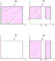
图3示出了在双门厢式机动车辆的情况下用于操作噪声传输系统的这些关闭装置的控制参数图;Figure 3 shows a diagram of the control parameters for operating these closing devices of the noise transmission system in the case of a coupe motor vehicle;
图4示出了在蓬式机动车辆的情况下用于操作噪声传输系统的这些关闭装置的控制参数图;并且Figure 4 shows a diagram of the control parameters for operating these closing devices of the noise transmission system in the case of a convertible motor vehicle; and
图5示出了用于操作机动车辆的排气系统的这些关闭装置的控制参数图。FIG. 5 shows a diagram of the control parameters for operating these shut-off devices of the exhaust system of a motor vehicle.
具体实施方式Detailed ways
本发明涉及一种机动车辆,这种机动车辆具有一个噪声传输系统10(见图1)以及一个排气系统34(见图2)。The invention relates to a motor vehicle having a noise transmission system 10 (see FIG. 1 ) and an exhaust system 34 (see FIG. 2 ).
通过噪声传输系统10,有可能的是在机动车辆的内部来影响限定的内部噪声水平以便根据机动车辆内燃发动机来为乘车者提供不同的噪声。该机动车辆的外部噪声水平能够受排气系统34影响。With the
噪声传输系统10具有一个进气噪声传输装置11,该进气噪声传输装置能够经由一个第一管状连接元件12与一个空气进气管13耦合并且经由一个第二管状连接元件14与机动车辆的内部(未示出)耦合。空气进气管13从一个空气过滤器装置15通向一个内燃发动机16,即通向内燃发动机16的一个空气进气系统17。该进气噪声传输装置11还被称为引擎声浪传导装置(sound symposer)并且它可以如从DE 10310487A1中已知的来予以构造。The
按照图1,第一管状连接元件12(经由该第一管状连接元件这个进气噪声传输装置11能够联接到空气进气管13上)配备有一个可切换的第一关闭装置18。According to FIG. 1 , the first tubular connecting
当第一关闭装置18打开时,进气噪声传输装置11被耦合到内燃发动机的进气噪声上,即耦合到空气进气管13的进气噪声上,而当第一关闭装置18关闭时,所述进气噪声传输装置11与所述进气噪声基本上是脱耦的。When the
该噪声传输系统10,除具有进气噪声传输装置11之外,优选地具有一个共振器装置19,该共振器装置与进气噪声传输装置11协同作用,其中共振器装置19优选是亥姆霍兹共振器。共振器装置19被调谐到一个限定的频率上,该频率也称为调谐频率。共振器装置19例如可以被调谐到240Hz的频率,尤其当该频率在内燃发动机的一个限定的转速范围内遭受该内燃发动机的一个振动等级(例如第三发动机振动等级)的强烈激振时。The
噪声传输系统10的共振器装置19能够经由一个第三管状连接元件20被耦合通向内燃发动机16的空气进气管13上,其方式与进气噪声传输装置11能够经由第一管状连接元件12进行耦合的方式相同。此处,为了使共振器装置19发挥功能,第三管状连接元件20就其长度和直径而言是与共振器装置19的容积大小相协调的。The
第三管状连接元件20(经由该第三管状连接元件共振器装置19能够耦合到进气管13上)配备有一个第二关闭装置21,如同配备有到第一管状连接元件12的第一关闭装置18,该第二关闭装置被配备为是可切换的。当第二可切换的关闭装置21打开时,共振器装置19被耦合到进气管13中的进气噪声上,而当第二关闭装置21关闭时,共振器装置19与进气管13中的进气噪声基本上脱耦。The third tubular connecting element 20 (via which the
通过进气噪声传输装置11,能够直接影响机动车辆内部的内部噪声水平。通过共振器装置19(该共振器装置优选地被设计为亥姆霍兹共振器),机动车辆内部的内部噪声水平可以被进气噪声传输装置11间接地影响。Via the intake
噪声传输系统10的这两个可切换的关闭装置18和21(即与进气噪声传输装置11协同作用的第一关闭装置18以及与共振器装置19协同作用的第二关闭装置21)能够被操作,并且因此被切换为使得在一个第一切换位置组合中,该可切换的第一关闭装置18被关闭而该可切换的第二关闭装置21被打开。因此,在该第一切换位置组合中,进气噪声传输装置11在这个关闭装置18被关闭时与进气管13中的进气噪声基本上脱耦,而共振器装置19在第二关闭装置21打开时是与进气管13中的进气噪声相耦合的。The two switchable shut-off
在这两个可切换的关闭装置18、21的一个第二切换位置组合中,可切换的第一关闭装置18以及还有可切换的第二关闭装置21均被关闭,于是其中进气噪声传输装置11以及还有共振器装置19均与进气管13中的进气噪声基本上脱耦。In a second combination of switching positions of the two
在这两个可切换的关闭装置18、21的一个第三切换位置组合中,可切换的关闭装置18和21均被打开,于是这样使得进气噪声传输装置11以及还有共振器装置19均与进气管13中的进气噪声相耦合。In a third combination of switching positions of the two
在一个第四切换位置组合中,可切换的第一关闭装置18打开而可切换的第二关闭装置21关闭,进气噪声传输装置11被耦合到进气管13中的进气噪声上,而共振器装置19与进气管13中的所述进气噪声基本上脱耦。In a fourth combination of switching positions, the first
在下表中汇总了这两个可切换的关闭装置18和21的以上四个切换位置组合:The above four switching position combinations of the two

以上第一切换位置组合(在该第一切换位置组合中,第一关闭装置18关闭而第二关闭装置21打开)用来在机动车辆内部(未示出)提供一个相对安静的第一内部噪声水平,其中所述第一内部噪声水平可称为舒适噪声水平。以上第二切换位置组合(在该第二切换位置组合中,两个关闭装置18、21均关闭)用来提供一个第二内部噪声水平,该第二内部噪声水平高于该第一内部噪声水平,其中该第二内部噪声水平可称为中间噪声水平。The above combination of the first switching position (in which the
以上第三切换位置组合(在该第三切换位置组合中,两个关闭元件18、21均打开)用来提供一个第三内部噪声水平,该第三内部噪声水平高于该第二内部噪声水平并且它因此也高于该第一内部噪声水平,其中所述第三内部噪声水平还可称为运动噪声水平。The above third combination of switching positions in which both
以上第四切换位置组合(在该第四切换位置组合中,第一关闭装置18打开而第二关闭装置21关闭)用来提供一个第四内部噪声水平,该第四内部噪声水平高于该第三内部噪声水平并且它因此还高于该第二以及第一内部噪声水平,其中所述第四内部噪声水平还可称为赛车式内部噪声水平。噪声传输系统10的这两个可切换的关闭装置18、21优选地被设计为翻板,这些翻板能够彼此独立地在一个打开的翻板位置与一个关闭的翻板位置之间运动。The above combination of the fourth switching position (in which the
如以上已经讨论的,第一管状连接元件12(经由该第一管状连接元件该进气噪声传输装置11能够耦合到空气进气管13上)以及第三管状连接元件20(经由该第三管状连接元件该共振器装置19能够耦合到进气管13上)分别接合在空气进气管13上,该空气进气管从空气过滤器装置15通向内燃发动机16,即通向内燃发动机16的空气进气系统17上,即所述接合是在空气过滤器装置15的下游以及被配备到空气进气管13上的一个节气门阀瓣22的上游发生的。如从图1中可见,在此提供的是第一管状连接元件12以及第三管状连接元件20相对于空气进气管13的流通方向23在同一个轴向位置处接合在空气进气管13上。As already discussed above, the first tubular connecting
该轴向位置(在该轴向位置处第一管状连接元件12以及第三管状连接元件20接合在空气进气管13上)的特征为,具有与共振器装置19的调谐频率相关的一个相对高的、优选最大的压力振荡幅值。The axial position at which the first
第一管状连接元件12以及第三管状连接元件20具有尤其在90°与270°之间的一个周向错位地在空气进气管13的这个轴向位置处接合在空气进气管13上。The first
图1的噪声传输系统10因此包括一个进气噪声传输装置11和一个共振器装置19。进气噪声传输装置11能够经由一个第一管状连接元件12被耦合到空气进气管13上,而共振器装置19能够经由一个第三管状连接元件20被耦合到空气进气管13上。进气噪声传输装置11能够经由一个第二管状连接元件14被耦合到机动车辆内部。进气噪声传输装置11以及还有共振器装置19分别均配备有一个可切换的关闭装置18和21,其中配备到进气噪声传输装置11上的关闭装置18被配备到第一管状连接元件12上,并且其中被配备到共振器装置19上的关闭装置21被配备到第三管状连接元件20上。在机动车辆的车辆内部中能够依据这些关闭装置18、21的切换位置来设置一个不同的内部噪声水平。The
机动车辆的排气系统34(见图2)包括至少一个前部消音器35,出现在内燃发动机16中的排气能够分别经由一个排气管36提供到该前部消音器上。这个或每个前部消音器35分别与一个后部消音器37协同作用,其中,对应的后部消音器37经由一个排气管38被联接到对应的前部消音器35上并且经由一个排气管39通向环境中。The exhaust system 34 of the motor vehicle (see FIG. 2 ) comprises at least one
经由一个排气管40(该排气管从这个或每个前部消音器35分支并且其上配备有多个关闭装置41),排气能够绕过这个或每个后部消音器37而被排放直接进入环境中。按照图2,优选的情况是每个前部消音器35与一个单独的、可切换的关闭装置41协同作用。也可以提供一个共同的可切换的关闭装置41用于这两个前部消音器35。Via an exhaust pipe 40 branching from the or each
当这个或每个关闭装置41关闭时,所有的排气必须流动经过这个或每个后部消音器37,由此能够设置机动车辆的一个相对低的外部噪声水平。当这个或每个关闭装置41打开时,一部分排气能够流动而绕过对应的后部消音器37,其结果是能够设置机动车辆的一个相对高的、运动型外部噪声水平。When the or each closing
为了自动操作这些关闭装置18、21、41,机动车辆包括一个控制装置24。控制装置24自动地操作噪声传输系统10的可切换的第一关闭装置18和/或可切换的第二关闭装置21以便设置内部噪声水平,并且该控制装置自动地操作排气系统34的这个或每个关闭装置41以便设置该外部噪声水平。For automatic operation of the
在控制装置24中,优选存在存储的多个控制参数图,基于这些控制参数图,这个控制装置24自动地操作(也就是说打开或关闭)噪声传输系统10的可切换的第一关闭装置18和/或可切换的第二关闭装置21。同样在控制装置24中存储了多个控制参数图,基于这些控制参数图,这个控制装置24自动地操作(也就是说打开或关闭)排气系统34的这个或每个关闭装置41。所述控制参数图至少与内燃发动机转速相关和/或与内燃发动机负载相关。依据由驾驶者操作一个安装在车辆内部中的共同的操作元件25,这个控制装置24确定用于自动地联合地操作噪声传输系统10的以及排气系统34的这些关闭装置18和/或21以及41的多个控制参数图。In the
用于影响进气噪声传输装置11的以及共振器装置19的这些关闭装置18、21的这些控制参数图优选还与机动车辆的车身结构类型相关。用于影响排气系统34的这个或每个关闭装置41的这些控制参数图相比之下与机动车辆的车身结构类型无关。The control parameter maps for influencing the shut-off
图3示出了总共四个控制参数图26、27、28和29,这些控制参数图用于自动操作噪声传输系统10的可切换的第一关闭装置18以及可切换的第二关闭装置21,如优选使用在双门厢式或四门厢式的机动车辆中。这些控制参数图中的每一个与内燃发动机的转速n以及内燃动机的负载L相关。FIG. 3 shows a total of four control parameter maps 26, 27, 28 and 29 for the automatic operation of the switchable first shut-off
在能够由驾驶者操作的操作元件25的优选未被致动的第一操作状态中,一个第一控制参数图26用于自动地操作噪声传输系统10的可切换的第一关闭装置18,而一个第二控制参数图27用于自动地操作噪声传输系统10的可切换的第二关闭装置21。用于自动地操作噪声传输系统10的可切换的第一关闭装置18的第一控制参数图26永久地关闭第一关闭装置18。用于自动地操作噪声传输系统10的可切换的第二关闭装置21的第二控制参数图27依据内燃发动机的转速n自动地打开或关闭第二关闭装置21,即使得当内燃发动机处于小于一个阈值L1的一个相对小的负载L时,第二控制参数图27在内燃发动机的整个转速范围上打开第二关闭装置21。相比之下,当内燃发动机处于高于该阈值L1的一个相对高的负载时,第二控制参数图27这样操作第二关闭装置21,使得当内燃发动机的转速小于一个下阈值n1或者高于一个上阈值n2时第二关闭装置21被关闭,而当内燃发动机的转速高于该下阈值n1并且低于这个上阈值n2时第二关闭装置21被打开。In the preferably non-actuated first operating state of the operating
图3和图4分别以阴影线的形式示出了多个控制参数图区域,在这些控制参数图区域中噪声传输系统10的对应的关闭装置被关闭,并且图3和图4以非阴影线的形式示出了多个控制参数图区域,在这些控制参数图区域中噪声传输系统10的对应的关闭装置被打开。Figures 3 and 4 each show, in hatched form, control parameter map areas in which the corresponding shut-off devices of the
在能够由驾驶者操作的操作元件25的一个优选被致动的第二操作状态中,一个第三控制参数图28用于自动地操作噪声传输系统10的可切换的第一关闭装置18,并且一个第四控制参数图29用于自动地操作噪声传输系统10的可切换的第二关闭装置21。用于自动地操作噪声传输系统10的可切换的第一关闭装置18的第三控制参数图28永久地打开第一关闭装置18。用于自动地操作噪声传输系统10的可切换的第二关闭装置21的第四控制参数图29依据内燃发动机的转速n并且与内燃发动机的负载L无关地自动地打开或关闭第二关闭装置21。第四控制参数图29自动地这样操作第二关闭装置21,使得当内燃发动机的转速小于一个下阈值n3或者高于一个上阈值n4时第二关闭装置21被关闭,而当内燃发动机的转速高于下阈值n3而低于上阈值n4时第二关闭装置21打开。In a preferably actuated second operating state of the driver-
阈值n3可以相当于阈值n1而阈值n4可以相当于阈值n2。然而所述阈值也可以是不同的。Threshold n3 may correspond to threshold n1 and threshold n4 may correspond to threshold n2. However, the threshold value can also be different.
图4示出总共四个控制参数图30、31、32和33,这些控制参数图用于自动地操作噪声传输系统10的可切换的第一关闭装置18以及噪声传输系统10的可切换的第二关闭装置21,如优选使用在蓬式机动车辆中。这四个控制参数图30、31、32和33中的每一个也与内燃发动机16的转速n的并且同样与内燃动机16的负载L相关。4 shows a total of four control parameter maps 30, 31, 32 and 33 for automatically operating the switchable
在蓬式机动车辆的情况下,在操作元件25的第一操作(具体是非致动的)状态中,用于自动地操作噪声传输系统10的可切换的第一关闭装置18的一个第一控制参数图30永久地关闭第一关闭装置18。在操作元件25的第一操作状态中,用于自动地操作噪声传输系统10的可切换的第二关闭装置21的一个第二控制参数图31依据内燃发动机的转速而自动地打开或关闭第二关闭装置21。因此,这些控制参数图30、31在操作元件25处于第一操作状态时是有效的。当内燃发动机处于低于一个阈值L5的一个相对低的负载时,用于自动地操作噪声传输系统10的可切换的第二关闭装置21的第二控制参数图31在内燃发动机的整个转速范围上打开第二关闭装置21,而当内燃发动机处于高于该阈值L5的一个相对较高的负载时,第二控制参数图31操作第二关闭装置21,从而使得在内燃发动机的转速小于一个阈值n5时第二关闭装置21被关闭,而当内燃发动机的转速高于阈值n5时第二关闭装置21被打开。In the case of a convertible motor vehicle, in the first operating (in particular non-actuated) state of the operating
在操作元件25的一个第二操作(具体是致动的)状态中,用于自动地操作噪声传输系统10的可切换的第一关闭装置18的一个第三控制参数图32以及用于自动地操作噪声传输系统10的可切换的第二关闭装置21的一个第四控制参数图33被启用而控制参数图30、31被解除启用,其中在各自情况中各自依据内燃发动机的转速,第三控制参数图32自动打开或关闭第一关闭装置18,而第四控制参数图33自动打开或关闭第二关闭装置21。与该内燃发动机的负载无关地,用于自动地操作噪声传输系统10的可切换的第一关闭装置18的第三控制参数图32操作第一关闭装置18,这样使得当内燃发动机的转速小于一个阈值n6时第一关闭装置18被打开而当内燃发动机的转速高于该阀值n6时第一关闭装置18被关闭。In a second operating (in particular actuated) state of the operating
与该内燃发动机的负载无关地,用于自动地操作噪声传输系统10的可切换的第二关闭装置21的第四控制参数图33自动地操作第二关闭装置21,这样使得当内燃发动机的转速小于一个下阈值n7或者高于一个上阈值n8时第二关闭装置21被关闭,而当内燃发动机的转速高于这个下阀值n7而小于这个上阈值n8时第二关闭装置21被打开。Regardless of the load of the internal combustion engine, the fourth
阈值n5可以相当于阈值n7而阈值n6可以相当于阈值n8。然而所述阈值也可以是不同的。Threshold n5 may correspond to threshold n7 and threshold n6 may correspond to threshold n8. However, the threshold value can also be different.
还有可能的是,在具有滑动顶篷或全景顶篷的车身结构类型的情况下,对于有待存储在控制装置24中的用于驱动该滑动顶篷或全景顶篷关闭以及用于驱动该滑动顶篷或全景顶篷打开的不同的控制参数图,所述控制参数图是由控制装置24依据滑动顶篷或全景顶篷的状态而自动启用的。用于关闭的滑动顶篷或全景顶篷的这些控制参数图可以相当于用于双门厢式的这些控制参数图,而用于打开滑动顶篷或全景顶篷的这些图谱可以相当于用于蓬式类型的这些控制参数图。It is also possible, in the case of a body structure type with a sliding roof or a panorama roof, to be stored in the
如已经陈述的,依据由驾驶者对共同的操作元件25的操作,控制装置24首先影响噪声传输系统10的运行,并且其次影响排气系统34的运行。图5示出了两个控制参数图42和43,基于这两个控制参数图,控制装置24影响排气系统34的运行,即排气系统34的这个或每个关闭装置41的运行。在操作元件25的该第一(具体是未被致动的)操作状态中,用于自动地操作排气系统34的这些可切换的关闭装置41的一个第一控制参数图42依据内燃发动机的转速n和负载L来打开和关闭这些关闭装置41,这样使得在转速n高于一个阈值n9并且负载L高于一个阈值L9时这些关闭装置41被打开。相比之下,当转速n低于该阈值n9和/或负载L小于该阈值L9时这些关闭装置41被关闭。As already stated, the
在操作元件25的该第二(具体被致动的)操作状态中,用于自动地操作排气系统34的这些可切换的关闭装置41的一个第二控制参数图43永久地打开这些关闭装置41。In the second (in particular actuated) operating state of the operating
图5分别以阴影线的形式示出了多个控制参数图区域,在这些控制参数图区域中排气系统34的这个或每个关闭装置41被打开,并且图5以非阴影线的形式示出了多个控制参数图区域,在这些控制参数图区域中排气系统34的这个或每个关闭装置41被关闭。FIG. 5 shows, in hatched form, control parameter map regions in which the or each closing
当操作元件25未被操作时,排气系统34的这些关闭装置41仅当内燃发动机处于高于该阈值n9的一个相对高的转速时并且内燃发动机同时处于高于该阈值L9的一个相对高的负载L时被打开,这样使得仅当内燃发动机处于相对高的转速和负载时提供一个相对高的、运动型外部噪声水平,同时确保了相对高的发动机性能。与之相比,当内燃发动机处于相对低的转速和/或相对低的负载时,当操作元件25未被操作时,排气系统34的这些关闭装置41被关闭,由此提供了一个相对低的外部噪声水平。而且,同时,在操作元件25未被操作时,通过相应操作这些关闭装置18和21而提供一个相对低的内部噪声水平。为此目的,当操作元件25处于非致动的操作状态时,一个控制参数图26或30永久地关闭进气噪声传输装置11的关闭装置18,其中,当内燃发动机处于低于该阈值L1或L5的一个相对低的负载时,另一个控制参数图27或31永久地打开共振器装置19的关闭装置21,并且当内燃发动机处于高于该阈值L1或L5的一个相对高的负载时依据转速来打开和关闭共振器装置19的关闭装置21。在此,当内燃发动机处于相对低的负载时,排气系统34的这个或每个关闭装置41通过控制参数图42被永久地关闭,其中该控制参数图42在内燃发动机处于相对高的负载时依据转速来打开和关闭排气系统34的这个或每个关闭装置41。When the operating
相比之下,当操作元件25被操作时,排气系统34的这些关闭装置41被永久地打开,从而永久提供一个相对高的运动型外部噪声水平。而且,同时,当操作元件25被操作时,通过对应操作这些关闭装置18和21而提供了一个相对高的内部噪声水平。为此目的,当操作元件25处于第二操作状态时,一个控制参数图28永久地打开进气噪声传输装置11的关闭装置18、或者一个控制参数图32依据转速来打开和关闭进气噪声传输装置11的关闭装置18,其中,依据转速,另一个控制参数图29或33打开和关闭共振器装置19的关闭装置21。In contrast, when the operating
参考符号清单list of reference symbols
10 噪声传输系统10 Noise transmission system
11进气噪声传输系统11 Intake noise transmission system
12 连接元件12 Connecting elements
13 进气管13 intake pipe
14 连接元件14 Connection elements
15 空气过滤器装置15 Air filter unit
16 内燃发动机16 internal combustion engine
17 进气系统17 intake system
18 关闭装置18 Closing device
19 共振器装置19 resonator device
20 连接元件20 connecting elements
21 关闭装置21 Closing device
22 节气门阀瓣22 Throttle valve disc
23 流动方向23 flow direction
24 控制装置24 control device
25 操作元件25 Operating elements
26 控制参数图26 Control parameter map
27 控制参数图27 Control parameter map
28 控制参数图28 Control parameter map
29 控制参数图29 Control parameter map
30 控制参数图30 Control parameter map
31 控制参数图31 Control parameter map
32 控制参数图32 Control parameter map
33 控制参数图33 Control parameter map
34 排气系统34 exhaust system
35 前部消音器35 front muffler
36 排气管36 exhaust pipe
37 后部消音器37 rear muffler
38 排气管38 exhaust pipe
39 排气管39 exhaust pipe
40 排气管40 exhaust pipe
41 关闭装置41 Closing device
42 控制参数图42 Control parameter map
43 控制参数图43 Control parameter map
Claims (10)
Applications Claiming Priority (2)
| Application Number | Priority Date | Filing Date | Title |
|---|---|---|---|
| DE102011051690.5ADE102011051690B4 (en) | 2011-07-08 | 2011-07-08 | Control device of a motor vehicle with a noise transmission system and an exhaust system |
| DE102011051690.5 | 2011-07-08 |
Publications (2)
| Publication Number | Publication Date |
|---|---|
| CN102867508Atrue CN102867508A (en) | 2013-01-09 |
| CN102867508B CN102867508B (en) | 2015-10-28 |
Family
ID=46704091
Family Applications (1)
| Application Number | Title | Priority Date | Filing Date |
|---|---|---|---|
| CN201210234940.8AExpired - Fee RelatedCN102867508B (en) | 2011-07-08 | 2012-07-06 | The control device of motor vehicles |
Country Status (5)
| Country | Link |
|---|---|
| US (1) | US8807274B2 (en) |
| KR (1) | KR101395458B1 (en) |
| CN (1) | CN102867508B (en) |
| DE (1) | DE102011051690B4 (en) |
| GB (1) | GB2492634B (en) |
Cited By (3)
| Publication number | Priority date | Publication date | Assignee | Title |
|---|---|---|---|---|
| CN103867363A (en)* | 2012-12-17 | 2014-06-18 | 现代自动车株式会社 | Active control sound generator |
| CN105121796A (en)* | 2013-05-15 | 2015-12-02 | 宝马股份公司 | Exhaust system for an internal combustion engine and method for operating the exhaust system |
| CN107346657A (en)* | 2016-05-05 | 2017-11-14 | 通用汽车环球科技运作有限责任公司 | Including with car audio bus(A2B)The vehicle of the clunk management system of interface |
Families Citing this family (13)
| Publication number | Priority date | Publication date | Assignee | Title |
|---|---|---|---|---|
| DE102011051689A1 (en) | 2011-07-08 | 2013-01-10 | Dr. Ing. H.C. F. Porsche Ag | Noise transmission system |
| DE102011051691A1 (en)* | 2011-07-08 | 2013-01-10 | Dr. Ing. H.C. F. Porsche Aktiengesellschaft | Noise transmission system |
| DE102011088150A1 (en)* | 2011-12-09 | 2013-06-13 | Kess-Tech Gmbh | Silencer arrangement |
| DE102013210464A1 (en)* | 2013-06-05 | 2014-12-11 | Bayerische Motoren Werke Aktiengesellschaft | Exhaust system for an internal combustion engine and method for operating the exhaust system |
| JP6075263B2 (en)* | 2013-10-04 | 2017-02-08 | 株式会社デンソー | Intake device for vehicle |
| KR101567698B1 (en)* | 2014-06-05 | 2015-11-23 | 현대자동차주식회사 | Variable intake valve with spring |
| US9706322B2 (en) | 2015-03-26 | 2017-07-11 | Honda Motor Co., Ltd. | System and method for leak detection in an engine sound transportation passageway |
| US9587535B2 (en) | 2015-04-09 | 2017-03-07 | K&N Engineering, Inc. | Drone elimination muffler |
| RS58305B1 (en)* | 2015-09-10 | 2019-03-29 | Akrapovic D D | Exhaust system for an internal combustion automotive engine |
| US10596898B2 (en)* | 2018-05-07 | 2020-03-24 | Tenneco Automotive Operating Company Inc. | Muffler assembly including a center muffler and two satellite mufflers |
| US10584626B2 (en) | 2018-05-07 | 2020-03-10 | Tenneco Automotive Operating Company Inc. | Muffler assembly including a center muffler and two satellite mufflers |
| US10767543B2 (en) | 2018-07-20 | 2020-09-08 | Tenneco Automotive Operating Company Inc. | Reduced length exhaust system with valve |
| US11255303B2 (en) | 2019-01-21 | 2022-02-22 | Toledo Molding & Die, Llc | Inline high frequency fiber silencer |
Citations (5)
| Publication number | Priority date | Publication date | Assignee | Title |
|---|---|---|---|---|
| CN1280241A (en)* | 1999-07-07 | 2001-01-17 | 韩国科学技术研究院 | Method and device for controlling noise of exhaust gas |
| DE10310487A1 (en)* | 2001-10-27 | 2004-09-23 | Mann + Hummel Gmbh | Noise transmission device for automobile with diesel engine or direct injection petrol engine has housing coupled to engine air intake containing throttle element and partition wall incorporating flap element |
| US6848410B2 (en)* | 2001-03-23 | 2005-02-01 | Mahle Filtersysteme Gmbh | Sound transmission device for a motor vehicle |
| US20070182525A1 (en)* | 2006-01-23 | 2007-08-09 | Mccarthy Mark W | Method and Apparatus for Selectively Varying Motor Vehicle Sounds |
| CN102086795A (en)* | 2009-12-02 | 2011-06-08 | 现代自动车株式会社 | Variable muffler |
Family Cites Families (33)
| Publication number | Priority date | Publication date | Assignee | Title |
|---|---|---|---|---|
| DE19641715A1 (en)* | 1996-10-10 | 1998-04-16 | Mann & Hummel Filter | Intake system for an internal combustion engine |
| DE19705273C1 (en)* | 1997-02-12 | 1998-03-05 | Porsche Ag | Induction system for internal combustion engine |
| DE19922216A1 (en)* | 1999-05-14 | 2000-11-30 | Mahle Filtersysteme Gmbh | Sound transmission device for a motor vehicle |
| DE10042012B4 (en) | 1999-11-22 | 2004-08-19 | Daimlerchrysler Ag | Device for noise shaping in a motor vehicle |
| DE10212257B4 (en)* | 2001-03-21 | 2004-08-26 | Daimlerchrysler Ag | Device for noise shaping in a motor vehicle |
| DE10222507A1 (en) | 2001-09-24 | 2003-05-08 | Daimler Chrysler Ag | Device for noise shaping in a motor vehicle |
| US6732510B2 (en)* | 2002-02-06 | 2004-05-11 | Arvin Technologies, Inc. | Exhaust processor with variable tuning system |
| US20050121255A1 (en)* | 2002-05-29 | 2005-06-09 | Marcus Hofmann | Device for establishing noise in a motor vehicle |
| US20050133300A1 (en)* | 2002-05-29 | 2005-06-23 | Marcus Hofmann | Device for establishing noise in a motor vehicle |
| DE10231056A1 (en)* | 2002-07-10 | 2004-02-05 | J. Eberspächer GmbH & Co. KG | exhaust system |
| DE112004002158T5 (en)* | 2003-11-06 | 2006-11-02 | Mahle Filter Systems Japan Corp. | Intake device of an internal combustion engine |
| DE102004041698B4 (en)* | 2004-08-28 | 2014-02-13 | Mann + Hummel Gmbh | Device for transmitting noise in a motor vehicle |
| DE102004041699A1 (en)* | 2004-08-28 | 2006-03-02 | Mann + Hummel Gmbh | Device for transmitting noise in a motor vehicle |
| JP4689363B2 (en)* | 2005-06-20 | 2011-05-25 | 日産自動車株式会社 | Sound increaser |
| DE102006039467A1 (en)* | 2005-08-26 | 2007-03-15 | Toyoda Gosei Co., Ltd., Nishikasugai | Control structure for the air intake noise |
| US7353791B2 (en) | 2005-10-07 | 2008-04-08 | Nissan Motor Co., Ltd. | Sound increase apparatus |
| JP4618122B2 (en) | 2005-12-28 | 2011-01-26 | 日産自動車株式会社 | Inspiratory sound amplifying device |
| KR100783950B1 (en) | 2006-12-06 | 2007-12-10 | 현대자동차주식회사 | Automotive Dual Mode Intake System |
| DE102007026812A1 (en)* | 2007-06-06 | 2008-12-11 | J. Eberspächer GmbH & Co. KG | exhaust system |
| JP2009007996A (en)* | 2007-06-27 | 2009-01-15 | Denso Corp | Tone quality controller of internal combustion engine |
| US8186323B2 (en)* | 2007-07-26 | 2012-05-29 | Nissan Motor Co., Ltd. | Intake air noise adjuster |
| US8009839B2 (en)* | 2008-03-13 | 2011-08-30 | Hagen Gary E | Automotive sensory enhancement system |
| JP4993755B2 (en)* | 2008-03-18 | 2012-08-08 | 日産自動車株式会社 | Intake sound generator |
| US20090319160A1 (en)* | 2008-06-24 | 2009-12-24 | Callahan Joseph E | Active exhaust valve control strategy for improved fuel consumption |
| ATE505628T1 (en)* | 2008-12-17 | 2011-04-15 | Magneti Marelli Spa | EXHAUST SYSTEM OF AN INTERNAL COMBUSTION ENGINE |
| DE102009032214B4 (en) | 2009-07-06 | 2023-10-19 | Dr. Ing. H.C. F. Porsche Aktiengesellschaft | Exhaust system of an internal combustion engine |
| KR100950997B1 (en) | 2009-09-15 | 2010-04-02 | (주) 피코사운드 | Variable muffler for sports mode |
| US8011469B2 (en)* | 2009-12-18 | 2011-09-06 | Mann & Hummel Gmbh | Tunable sound transmission device for a motor vehicle |
| JP5639794B2 (en)* | 2010-06-23 | 2014-12-10 | 株式会社マーレ フィルターシステムズ | Intake sound generator for internal combustion engine |
| US8127888B1 (en)* | 2011-02-02 | 2012-03-06 | Mann + Hummel, GmbH | Engine sound distribution apparatus for a motor vehicle |
| DE102011051689A1 (en)* | 2011-07-08 | 2013-01-10 | Dr. Ing. H.C. F. Porsche Ag | Noise transmission system |
| DE102011051691A1 (en)* | 2011-07-08 | 2013-01-10 | Dr. Ing. H.C. F. Porsche Aktiengesellschaft | Noise transmission system |
| US8381871B1 (en)* | 2011-09-28 | 2013-02-26 | Visteon Global Technologies, Inc. | Compact low frequency resonator |
- 2011
- 2011-07-08DEDE102011051690.5Apatent/DE102011051690B4/enactiveActive
- 2012
- 2012-06-22GBGB1211145.6Apatent/GB2492634B/ennot_activeExpired - Fee Related
- 2012-07-02USUS13/539,743patent/US8807274B2/enactiveActive
- 2012-07-06CNCN201210234940.8Apatent/CN102867508B/ennot_activeExpired - Fee Related
- 2012-07-06KRKR1020120073713Apatent/KR101395458B1/ennot_activeExpired - Fee Related
Patent Citations (5)
| Publication number | Priority date | Publication date | Assignee | Title |
|---|---|---|---|---|
| CN1280241A (en)* | 1999-07-07 | 2001-01-17 | 韩国科学技术研究院 | Method and device for controlling noise of exhaust gas |
| US6848410B2 (en)* | 2001-03-23 | 2005-02-01 | Mahle Filtersysteme Gmbh | Sound transmission device for a motor vehicle |
| DE10310487A1 (en)* | 2001-10-27 | 2004-09-23 | Mann + Hummel Gmbh | Noise transmission device for automobile with diesel engine or direct injection petrol engine has housing coupled to engine air intake containing throttle element and partition wall incorporating flap element |
| US20070182525A1 (en)* | 2006-01-23 | 2007-08-09 | Mccarthy Mark W | Method and Apparatus for Selectively Varying Motor Vehicle Sounds |
| CN102086795A (en)* | 2009-12-02 | 2011-06-08 | 现代自动车株式会社 | Variable muffler |
Cited By (4)
| Publication number | Priority date | Publication date | Assignee | Title |
|---|---|---|---|---|
| CN103867363A (en)* | 2012-12-17 | 2014-06-18 | 现代自动车株式会社 | Active control sound generator |
| CN105121796A (en)* | 2013-05-15 | 2015-12-02 | 宝马股份公司 | Exhaust system for an internal combustion engine and method for operating the exhaust system |
| CN105121796B (en)* | 2013-05-15 | 2018-05-15 | 宝马股份公司 | Method for the exhaust equipment of internal combustion engine and for running exhaust equipment |
| CN107346657A (en)* | 2016-05-05 | 2017-11-14 | 通用汽车环球科技运作有限责任公司 | Including with car audio bus(A2B)The vehicle of the clunk management system of interface |
Also Published As
| Publication number | Publication date |
|---|---|
| GB2492634A (en) | 2013-01-09 |
| GB201211145D0 (en) | 2012-08-08 |
| CN102867508B (en) | 2015-10-28 |
| GB2492634B (en) | 2013-10-30 |
| DE102011051690B4 (en) | 2023-06-29 |
| US8807274B2 (en) | 2014-08-19 |
| KR20130006361A (en) | 2013-01-16 |
| DE102011051690A1 (en) | 2013-01-10 |
| KR101395458B1 (en) | 2014-05-14 |
| US20130008737A1 (en) | 2013-01-10 |
Similar Documents
| Publication | Publication Date | Title |
|---|---|---|
| CN102867508B (en) | The control device of motor vehicles | |
| CN102867507B (en) | noise transmission system | |
| CN102865169B (en) | Noise transmission system | |
| US7506723B2 (en) | Muffler for an exhaust gas system | |
| CN107429585B (en) | Exhaust system | |
| US9109483B2 (en) | Exhaust system for an internal combustion engine | |
| US9683528B2 (en) | Apparatus for cooling vehicle intake air temperature and method using the same | |
| WO2017079156A1 (en) | Muffler with selected exhaust pathways | |
| US6135079A (en) | Air intake system for an internal combustion engine | |
| CN106340289A (en) | Sound transmitting system for a motor vehicle and method for a sound transmitting system | |
| US20110114050A1 (en) | Variable intake duct structure of engine | |
| US20160273424A1 (en) | Mounting structure of variable valve for dual exhaust system | |
| JP2005076619A (en) | Intake sound control device for vehicular engine | |
| US20050121254A1 (en) | Device for establishing noise in a motor vehicle | |
| JP4506417B2 (en) | Blow-by gas processing device for internal combustion engine | |
| US8770166B2 (en) | Multi-mode air induction tuning duct | |
| US20040226537A1 (en) | Exhaust line of an internal combustion engine having controllable exhaust flaps | |
| JPH0727028A (en) | Intake device of engine | |
| JP2003502560A (en) | Intake device for internal combustion engine | |
| CN111075536B (en) | Variable valve for muffler and double muffler having the same | |
| CN207644258U (en) | For noise transmission system and vehicle with motor and the vehicle of vehicle passenger cabin | |
| JPH11210574A (en) | Diesel engine with exhaust gas recirculation(egr) system | |
| JP2005139919A (en) | Control muffler system |
Legal Events
| Date | Code | Title | Description |
|---|---|---|---|
| C06 | Publication | ||
| PB01 | Publication | ||
| C10 | Entry into substantive examination | ||
| SE01 | Entry into force of request for substantive examination | ||
| C14 | Grant of patent or utility model | ||
| GR01 | Patent grant | ||
| CF01 | Termination of patent right due to non-payment of annual fee | Granted publication date:20151028 | |
| CF01 | Termination of patent right due to non-payment of annual fee |