CN102856912A - Multi-target multi-site reactive power coordination control method - Google Patents
Multi-target multi-site reactive power coordination control methodDownload PDFInfo
- Publication number
- CN102856912A CN102856912ACN2012103396054ACN201210339605ACN102856912ACN 102856912 ACN102856912 ACN 102856912ACN 2012103396054 ACN2012103396054 ACN 2012103396054ACN 201210339605 ACN201210339605 ACN 201210339605ACN 102856912 ACN102856912 ACN 102856912A
- Authority
- CN
- China
- Prior art keywords
- reactive power
- voltage
- control
- low
- coordination control
- Prior art date
- Legal status (The legal status is an assumption and is not a legal conclusion. Google has not performed a legal analysis and makes no representation as to the accuracy of the status listed.)
- Granted
Links
- 238000000034methodMethods0.000titleclaimsdescription10
- 239000003990capacitorSubstances0.000claimsabstractdescription18
- 230000001939inductive effectEffects0.000claimsdescription3
- 238000012544monitoring processMethods0.000claimsdescription3
- 230000003993interactionEffects0.000abstractdescription10
- 230000000087stabilizing effectEffects0.000abstractdescription5
- 238000011217control strategyMethods0.000abstractdescription3
- 230000009467reductionEffects0.000abstractdescription3
- 238000009434installationMethods0.000abstract1
- 238000005457optimizationMethods0.000description3
- 239000000243solutionSubstances0.000description2
- 230000005540biological transmissionEffects0.000description1
- 238000004364calculation methodMethods0.000description1
- 238000010276constructionMethods0.000description1
- 238000010586diagramMethods0.000description1
- 230000009977dual effectEffects0.000description1
- 230000000694effectsEffects0.000description1
- 238000005516engineering processMethods0.000description1
- 230000002068genetic effectEffects0.000description1
- 238000002347injectionMethods0.000description1
- 239000007924injectionSubstances0.000description1
- 238000002844meltingMethods0.000description1
- 238000012986modificationMethods0.000description1
- 230000004048modificationEffects0.000description1
Images

Classifications
- Y—GENERAL TAGGING OF NEW TECHNOLOGICAL DEVELOPMENTS; GENERAL TAGGING OF CROSS-SECTIONAL TECHNOLOGIES SPANNING OVER SEVERAL SECTIONS OF THE IPC; TECHNICAL SUBJECTS COVERED BY FORMER USPC CROSS-REFERENCE ART COLLECTIONS [XRACs] AND DIGESTS
- Y02—TECHNOLOGIES OR APPLICATIONS FOR MITIGATION OR ADAPTATION AGAINST CLIMATE CHANGE
- Y02E—REDUCTION OF GREENHOUSE GAS [GHG] EMISSIONS, RELATED TO ENERGY GENERATION, TRANSMISSION OR DISTRIBUTION
- Y02E40/00—Technologies for an efficient electrical power generation, transmission or distribution
- Y02E40/30—Reactive power compensation
Landscapes
- Control Of Electrical Variables (AREA)
- Supply And Distribution Of Alternating Current (AREA)
Abstract
Translated fromChineseDescription
Translated fromChinese技术领域technical field
本发明涉及电力系统自动控制领域,特别是涉及构建考虑装置损耗和站间无功交互作用的多目标多站点无功协调控制系统。The invention relates to the field of automatic control of power systems, in particular to the construction of a multi-objective and multi-site reactive power coordination control system considering device loss and reactive power interaction between stations.
背景技术Background technique
电力系统运行中由于存在负荷的增减、故障等扰动因素,系统节点电压会偏离基于全网网损最优化计算得到的参考电压值。为了达到稳定系统电压的目的,需要在系统重要节点进行动态无功补偿。During the operation of the power system, due to disturbance factors such as load increase and decrease, faults, etc., the system node voltage will deviate from the reference voltage value calculated based on the optimization calculation of the entire network network loss. In order to achieve the purpose of stabilizing the system voltage, it is necessary to carry out dynamic reactive power compensation at important nodes of the system.
南方电网“西电东送”主通道中没有主力电厂接入、动态无功支撑较弱,因此在500kV枢纽变电站中安装了直流融冰兼SVC装置、低容低抗等无功补偿装置。但在实际运行中并没有协调无功装置之间的投切和TCR电流、低容低抗发热等损耗因素,从而导致无功补偿装置的损耗较大。据统计,桂林站直流融冰兼SVC装置处于SVC模式运行时,每月有功电量消耗达50万kWh,运行的经济性能指标欠佳。因此有必要对系统无功补偿装置的协调投切策略进行深入研究,通过最优的投切策略,稳定系统电压的同时减少装置本身电量损耗,达到节能降耗、安全稳定经济运行的目的。There is no main power plant connected to the main channel of China Southern Power Grid's "West to East Power Transmission", and the dynamic reactive power support is weak. Therefore, reactive power compensation devices such as DC ice-melting and SVC devices, low-capacity and low-resistance devices are installed in the 500kV hub substation. However, in actual operation, there is no coordination of switching between reactive power devices and loss factors such as TCR current, low capacity and low heat resistance, resulting in large losses in reactive power compensation devices. According to statistics, when the DC deicing and SVC device in Guilin Station is in SVC mode, the monthly active power consumption reaches 500,000 kWh, and the economic performance index of operation is not good. Therefore, it is necessary to conduct in-depth research on the coordinated switching strategy of the reactive power compensation device of the system. Through the optimal switching strategy, the system voltage can be stabilized while reducing the power loss of the device itself, so as to achieve the goals of energy saving, consumption reduction, safe and stable economic operation.
针对无功的协调控制问题,现有研究更多集中于最优潮流的研究,通过控制系统无功补偿设备的运行状态,调整系统潮流分布,使得本已正常运行的电力系统处于更优的运行状态。有文献提出一种最优匹配注入流法研究了电容器的优化投切,使得系统网损和支路负载达到最优;另有文献分别采用原对偶内点法和改进的遗传算法对无功优化进行研究。现有研究大部分以全网网损最小为目标进行无功优化,而实际系统运行中,无功装置主要根据已经全网优化得到的电压目标值进行动态补偿,使得节点电压稳定在目标值附近,该电压目标值由上一级调度中心下发得到,因此考虑补偿后节点电压与目标值的偏差和无功装置总损耗在电力系统中更具有实用性,针对这方面现有文献少有研究。Aiming at the problem of reactive power coordination control, existing research focuses more on optimal power flow research. By controlling the operating state of reactive power compensation equipment in the system, the power flow distribution of the system can be adjusted, so that the power system that is already in normal operation can be in better operation. state. Some literature proposes an optimal matching injection flow method to study the optimal switching of capacitors, so that the system network loss and branch load can be optimized; another literature uses the original dual interior point method and the improved genetic algorithm to optimize the reactive power research. Most of the existing research focuses on reactive power optimization with the goal of minimizing the network loss of the entire network. In actual system operation, reactive power devices are mainly dynamically compensated according to the voltage target value obtained by the entire network optimization, so that the node voltage is stabilized near the target value. , the voltage target value is issued by the upper-level dispatching center. Therefore, it is more practical in the power system to consider the deviation between the node voltage and the target value after compensation and the total loss of reactive power devices. There are few existing studies on this aspect .
本发明是在国家863计划项目基金资助下,提供的一种能够考虑无功装置损耗和站间无功交互作用,在稳定电压的同时节能减损,能广泛适用于实现实际电网安全、稳定、经济运行的无功协调控制系统。Under the support of the national 863 plan project fund, the present invention provides a kind of reactive power device loss and reactive power interaction between stations, which can save energy and reduce loss while stabilizing the voltage, and can be widely used to realize the safety, stability and economy of the actual power grid. The running reactive power coordination control system.
发明内容Contents of the invention
本发明的目的在于提出构建考虑装置损耗和站间无功交互作用的多目标多站点无功协调控制系统,稳定电压的同时节能减损,实现电网的安全、稳定和经济运行。The purpose of the present invention is to propose to construct a multi-objective multi-site reactive power coordination control system considering device loss and reactive power interaction between stations, to stabilize voltage while saving energy and reducing loss, and to realize safe, stable and economical operation of the power grid.
为达到上述目的,采用的技术方案是:In order to achieve the above purpose, the technical scheme adopted is:
a.根据运行电压与电压目标值的偏差,确定需要参与无功协调控制的N个控制站点;a. According to the deviation between the operating voltage and the voltage target value, determine the N control stations that need to participate in reactive power coordinated control;
b.根据站点的实际运行情况,获取各个控制站点中无功装置的运行状态和容量参数,该获取是现有常见技术,在此不做详细阐述;b. Obtain the operating status and capacity parameters of the reactive devices in each control station according to the actual operating conditions of the station. This acquisition is a common technology in the present and will not be elaborated here;
c.根据站内无功装置的运行状态,将离散型无功补偿装置(如低压电容器、低压电抗器)纳入连续型无功补偿装置(如SVC装置)的控制体系,建立各个控制站点的站内无功协调控制模型;c. Incorporate discrete reactive power compensation devices (such as low-voltage capacitors and low-voltage reactors) into the control system of continuous reactive power compensation devices (such as SVC devices) according to the operating status of reactive power devices in the station, and establish reactive power compensation devices for each control station. Work coordination control model;
d.联合N个控制站点,构建考虑装置损耗的多目标多站点的无功协调控制系统;d. Combine N control sites to build a multi-objective and multi-site reactive power coordination control system considering device loss;
e.求解多目标多站点的无功协调控制模型;e. Solve the reactive power coordination control model of multi-objective and multi-site;
f.输出各控制站点的无功装置调节量;f. Output the adjusted amount of reactive power devices of each control station;
g.根据无功装置的调节量进行无功协调控制。g. Carry out reactive power coordination control according to the adjustment amount of reactive power devices.
本发明提出的构建考虑装置损耗和站间无功交互作用的多目标多站点无功协调控制系统,首先根据运行电压与电压目标值的偏差,确定需要参与无功协调控制的N个控制站点;同时获取各个控制站点中所有无功补偿装置的运行状态和设备容量参数;根据站内无功装置的运行状态,将离散型无功补偿装置(如低压电容器、低压电抗器)纳入连续型无功补偿装置(如SVC装置)的控制体系,建立各个控制站点的站内无功协调控制模型;联合N个控制站点,构建考虑装置总损耗、电压总偏差等多目标多站点的无功协调控制系统;求解系统的无功协调控制模型,根据得到的各个控制站点中无功装置的调节量进行无功协调控制。通过该无功协调控制系统的求解为决策者提供最优协调控制策略,达到稳定系统电压的同时节能降耗的目的。The present invention proposes to construct a multi-objective multi-site reactive power coordination control system that considers device loss and reactive power interaction between stations. First, according to the deviation between the operating voltage and the voltage target value, determine the N control stations that need to participate in the reactive power coordination control; At the same time, obtain the operating status and equipment capacity parameters of all reactive power compensation devices in each control station; according to the operating status of reactive power devices in the station, incorporate discrete reactive power compensation devices (such as low-voltage capacitors and low-voltage reactors) into continuous reactive power compensation For the control system of the device (such as SVC device), establish a reactive power coordination control model in each control station; combine N control stations to construct a reactive power coordination control system that considers the total loss of the device, the total voltage deviation, etc. The reactive power coordination control model of the system performs reactive power coordination control according to the adjusted quantities of reactive power devices in each control station. Through the solution of the reactive power coordinated control system, the optimal coordinated control strategy is provided for decision makers, so as to achieve the purpose of stabilizing the system voltage while saving energy and reducing consumption.
所述根据运行电压与电压目标值的偏差,确定需要参与无功协调控制的N个控制站点的步骤具体为:According to the deviation between the operating voltage and the voltage target value, the steps of determining the N control stations that need to participate in the reactive power coordinated control are specifically:
电网实际运行中电压需跟踪上一级调度中心下发的电压参考值,允许在预定范围内波动,若波动超出该预定范围则无功补偿装置动作,进行无功调节;In the actual operation of the power grid, the voltage needs to track the voltage reference value issued by the upper-level dispatching center, allowing fluctuations within a predetermined range. If the fluctuation exceeds the predetermined range, the reactive power compensation device will operate to perform reactive power adjustment;
根据公式:判断各个监控节点的电压波动情况,确定需要参与无功协调控制的所有站点;其中Vi、
根据站内无功装置的运行状态,将离散型无功补偿装置纳入连续型无功补偿装置的控制体系,建立各个控制站点的站内无功协调控制模型的具体步骤为:According to the operating status of the reactive power devices in the station, the discrete reactive power compensation device is incorporated into the control system of the continuous reactive power compensation device, and the specific steps for establishing the reactive power coordination control model in the station of each control station are as follows:
a.考虑SVC滤波器组FC11和FC13的投切,可构建出两种新的SVC运行方式,即切除FC11或者切除FC11和FC13;a. Considering the switching of SVC filter banks FC11 and FC13, two new SVC operation modes can be constructed, that is, cut off FC11 or cut off FC11 and FC13;
b.考虑低压电容器的投入时,可构建出投1组低容到投m组低容的方式;同理投入低压电抗器时,可构建出投1组低抗到投n组低抗的方式;b. When considering the input of low-voltage capacitors, it is possible to construct a method of switching from 1 group of low-capacity to m-groups of low-capacity; similarly, when inputting low-voltage reactors, it can be constructed from 1 group of low-resistance to n-groups of low-resistance ;
c.对于具有m组低容、n组低抗和一台SVC的变电站,其无功装置协调控制系统中SVC具有3×(n+m+1)个投切方式;c. For a substation with m groups of low capacity, n groups of low reactance and one SVC, the SVC in its reactive device coordination control system has 3×(n+m+1) switching modes;
d.站内无功协调控制系统还规定了低容低抗装置的投切优先级,当系统存在容性无功缺额时,切除低压电抗器具有最高优先级,投入低压电容器次之;当系统存在感性无功缺额时,切除低压电容器优先级最高,投入低压电抗器次之;由于无功联合控制系统具有多种运行方式,通过选取最优的运行方式可有效地降低无功装置总损耗。d. The reactive power coordination control system in the station also stipulates the switching priority of low-capacity and low-resistance devices. When there is a capacitive reactive power shortage in the system, the removal of low-voltage reactors has the highest priority, followed by the input of low-voltage capacitors; when the system exists In the case of inductive reactive power shortage, the priority of removing low-voltage capacitors is the highest, followed by the input of low-voltage reactors; since the reactive power joint control system has multiple operating modes, the total loss of reactive power devices can be effectively reduced by selecting the optimal operating mode.
所述的构建考虑装置损耗的多目标多站点的无功协调控制系统模型为:The multi-objective multi-site reactive power coordination control system model considering device loss is described as:
式中:Fp与Fv分别为系统参与无功协调控制站点的无功装置总损耗和电压总偏移,N为参与无功协调控制站点的集合,u、x分别为控制变量和代数变量;fi为第i个变电站无功装置的总损耗,包括SVC装置损耗psvc、低压电容器损耗pcap和低压电抗器损耗prea;Vi、

本发明与现有技术相比,具有如下优点:本发明考虑了无功装置的运行损耗,考虑了站内不同类型无功装置的最优协调运行,考虑了不同站点间无功补偿的交互作用,从而实现多目标多站点的最优无功协调控制。现有技术中站内各种无功补偿装置单独进行补偿,投切量依靠经验值,也不考虑无功装置之间,站与站之间的交互作用,经济性和调节效果差。本发明通过构建联合的无功协调控制系统,求解最优的投切策略,稳定系统电压的同时减少装置本身电量损耗,达到节能降耗、安全稳定经济运行的目的,能广泛适应实际电网运行的需要。Compared with the prior art, the present invention has the following advantages: the present invention considers the operating loss of reactive power devices, considers the optimal coordinated operation of different types of reactive power devices in the station, and considers the interaction of reactive power compensation between different stations, In this way, the optimal reactive power coordinated control of multi-objective and multi-site can be realized. In the prior art, various reactive power compensation devices in the station perform compensation independently, and the switching amount depends on empirical values, and the interaction between reactive power devices and stations is not considered, so the economy and adjustment effect are poor. The invention solves the optimal switching strategy by constructing a joint reactive power coordination control system, stabilizes the system voltage and reduces the power loss of the device itself, so as to achieve the purpose of energy saving, safe and stable economic operation, and can be widely adapted to the actual power grid operation need.
附图说明Description of drawings
图1为本发明的一个实例流程图;Fig. 1 is an example flowchart of the present invention;
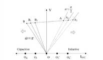
图2为本发明中站内SVC的伏安特性曲线。Fig. 2 is the volt-ampere characteristic curve of the SVC in the station in the present invention.
具体实施方式Detailed ways
为便于理解本发明,下面结合附图进行阐述。In order to facilitate understanding of the present invention, the following will be described in conjunction with the accompanying drawings.
本发明提出构建考虑装置损耗和站间无功交互作用的多目标多站点无功协调控制系统,请参考图1,包括步骤:The present invention proposes to construct a multi-objective multi-site reactive power coordination control system considering device loss and reactive power interaction between stations, please refer to Figure 1, including steps:
S101:确定需要参与无功协调控制的N个控制站点;S101: Determine N control stations that need to participate in reactive power coordinated control;
S102:获取各个控制站点中无功装置的运行状态和容量参数;S102: Obtain the operating status and capacity parameters of the reactive devices in each control station;
S103:建立各个控制站点的站内无功协调控制模型;S103: Establish reactive power coordination control models in each control station;
根据站内无功装置的运行状态,将离散型无功补偿装置(如电容器、电抗器)纳入连续型无功补偿装置(如SVC装置)控制体系,构建各个控制站点的站内无功协调控制模型;According to the operating status of reactive power devices in the station, the discrete reactive power compensation devices (such as capacitors and reactors) are included in the control system of continuous reactive power compensation devices (such as SVC devices), and the reactive power coordination control model in each control station is constructed;
S104:构建考虑装置损耗的多目标多站点的无功协调控制系统;S104: Construct a multi-objective and multi-site reactive power coordinated control system considering device loss;
S105:求解多目标多站点的无功协调控制模型;S105: Solve the reactive power coordination control model of multi-objective and multi-site;
S106:输出各个控制站点的无功装置调节量;S106: output the adjusted amount of reactive power devices of each control station;
S107:根据各个控制站点无功装置的调节量进行无功协调控制。S107: Carry out reactive power coordination control according to the adjustment quantities of reactive power devices at each control station.
本发明提出的构建考虑装置损耗和站间无功交互作用的多目标多站点无功协调控制系统,首先根据运行电压与电压目标值的偏差,确定需要参与无功协调控制的N个控制站点;同时获取各个控制站点中所有无功补偿装置的运行状态和设备容量参数;根据站内无功装置的运行状态,将离散型无功补偿装置(如低压电容器、低压电抗器)纳入连续型无功补偿装置(如SVC装置)的控制体系,建立各个控制站点的站内无功协调控制模型;联合N个控制站点(以考虑多于2个的控制站点的无功协调控制),构建考虑装置总损耗、电压总偏差等多目标多站点的无功协调控制系统;求解系统的无功协调控制模型,根据得到的各个控制站点中无功装置的调节量进行无功协调控制。通过该无功协调控制系统的求解为决策者提供最优协调控制策略,达到稳定系统电压的同时节能降耗的目的。The present invention proposes to construct a multi-objective multi-site reactive power coordination control system that considers device loss and reactive power interaction between stations. First, according to the deviation between the operating voltage and the voltage target value, determine the N control stations that need to participate in the reactive power coordination control; At the same time, obtain the operating status and equipment capacity parameters of all reactive power compensation devices in each control station; according to the operating status of reactive power devices in the station, incorporate discrete reactive power compensation devices (such as low-voltage capacitors and low-voltage reactors) into continuous reactive power compensation For the control system of the device (such as SVC device), establish the reactive power coordination control model in each control station; combine N control stations (to consider the reactive power coordination control of more than 2 control stations), and construct a system that considers the total loss of the device, Multi-objective multi-site reactive power coordinated control system such as voltage total deviation; solve the reactive power coordinated control model of the system, and perform reactive power coordinated control according to the obtained adjustment amount of reactive power devices in each control site. Through the solution of the reactive power coordinated control system, the optimal coordinated control strategy is provided for decision makers, so as to achieve the purpose of stabilizing the system voltage while saving energy and reducing consumption.
在其中一个实施方式中,上述S101步骤包括:In one of the implementation manners, the above step S101 includes:
获取站点的运行电压和上级调度中心下发的电压目标值,电网实际运行中节点电压波动允许范围为±3kV。若波动超出范围则无功补偿装置动作进行调节。Obtain the operating voltage of the site and the voltage target value issued by the superior dispatching center. The allowable range of node voltage fluctuations in the actual operation of the power grid is ±3kV. If the fluctuation exceeds the range, the reactive power compensation device will act to adjust.
根据公式:

上述S103步骤中建立各个控制站点的站内无功协调控制模型为:In the above S103 step, the reactive power coordination control model in each control station is established as follows:
根据站内无功装置的运行状态,将离散型无功补偿装置纳入连续型无功补偿装置构成站内无功协调控制系统,该系统运行方式多样,无功连续调节范围广,且能有效调节TCR电流,从而实现降损节能。以具有m组低容、n组低抗和一台SVC装置的某站点为例,图2给出了该无功协调控制系统中SVC的伏安特性图。According to the operating status of reactive power devices in the station, the discrete reactive power compensation device is incorporated into the continuous reactive power compensation device to form a reactive power coordination control system in the station. The system has various operating modes, a wide range of reactive power continuous adjustment, and can effectively adjust the TCR current. , so as to achieve loss reduction and energy saving. Taking a site with m groups of low capacity, n groups of low reactance and one SVC device as an example, Figure 2 shows the volt-ampere characteristic diagram of SVC in the reactive power coordinated control system.
图2中曲线OBA为SVC原有的伏安特性曲线。在协调控制系统中,考虑SVC滤波器组FC11和FC13的投切,可构建出两种新的SVC运行方式,对应图中伏安特性曲线OB1A1(切除FC11)和OB2A2(切除FC11和FC13)。考虑低压电容器的投入时,SVC的伏安特性曲线将左移,原点O移至O1(投1组低容)、Om(投m组低容);同理投入低压电抗器时,SVC的伏安特性曲线将右移,原点O移至O1’(投1组低抗)、On’(投n组低抗)。因此,对于具有m组低容、n组低抗和一台SVC的变电站,其无功装置协调控制系统中SVC具有3×(n+m+1)条伏安特性曲线,大大增多了SVC运行方式的多样性,其无功的连续调节范围也增大。The curve OBA in Fig. 2 is the original volt-ampere characteristic curve of SVC. In the coordinated control system, considering the switching of SVC filter banks FC11 and FC13, two new SVC operation modes can be constructed, corresponding to the volt-ampere characteristic curve OB1 A1 (cut FC11) and OB2 A2 ( Excision of FC11 and FC13). When considering the input of low-voltage capacitors, the volt-ampere characteristic curve of SVC will shift to the left, and the origin O will move to O1 (with low capacity for 1 group), Om (with low capacity for m groups); similarly, when low-voltage reactors are used, SVC The volt-ampere characteristic curve will move to the right, and the origin O will move to O1 ' (throwing 1 group of low resistance), On ' (throwing n groups of low resistance). Therefore, for a substation with m groups of low capacity, n groups of low reactance and one SVC, the SVC in its reactive device coordination control system has 3×(n+m+1) volt-ampere characteristic curves, which greatly increases the SVC operation The diversity of the ways, the continuous adjustment range of its reactive power also increases.
站内无功协调控制系统还规定了低容低抗装置的投切优先级。当系统存在容性无功缺额时,切除低压电抗器具有最高优先级,投入低压电容器次之;当系统存在感性无功缺额时,切除低压电容器优先级最高,投入低压电抗器次之。由于无功联合控制系统具有多种运行方式,通过选取最优的运行方式可有效地降低无功装置总损耗。The reactive power coordination control system in the station also stipulates the switching priority of low-capacity and low-resistance devices. When there is a capacitive reactive power shortage in the system, removing the low-voltage reactor has the highest priority, followed by putting in the low-voltage capacitor; when there is an inductive reactive power shortage in the system, cutting off the low-voltage capacitor has the highest priority, followed by putting in the low-voltage reactor. Since the reactive power joint control system has multiple operating modes, the total loss of reactive power devices can be effectively reduced by selecting the optimal operating mode.
在其中一个实施方式中,上述S104步骤中构建考虑装置损耗和站间无功交互作用的多目标多站点的无功协调控制系统模型为:In one of the implementations, the multi-target multi-site reactive power coordination control system model considering device loss and inter-station reactive power interaction in the above S104 step is:
式中:Fp与Fv分别为系统参与无功协调控制站点的无功装置总损耗和电压总偏移,N为参与无功协调控制站点的集合,u、x分别为控制变量和代数变量;fi为第i个变电站无功装置的总损耗,包括SVC装置损耗psvc、低压电容器损耗pcap和低压电抗器损耗prea;Vi、

以上所述实施例仅表达了本发明的几种实施方式,其描述较为具体和详细,但并不能因此而理解为对本发明专利范围的限制。应当指出的是,对于本领域的普通技术人员来说,在不脱离本发明构思的前提下,还可以做出若干变形和改进,这些都属于本发明的保护范围。因此,本发明专利的保护范围应以所附权利要求为准。The above-mentioned embodiments only express several implementation modes of the present invention, and the description thereof is relatively specific and detailed, but should not be construed as limiting the patent scope of the present invention. It should be pointed out that those skilled in the art can make several modifications and improvements without departing from the concept of the present invention, and these all belong to the protection scope of the present invention. Therefore, the protection scope of the patent for the present invention should be based on the appended claims.
Claims (4)
Translated fromChinese


Priority Applications (1)
| Application Number | Priority Date | Filing Date | Title |
|---|---|---|---|
| CN201210339605.4ACN102856912B (en) | 2012-09-13 | 2012-09-13 | Multi-target multi-site reactive power coordination control method |
Applications Claiming Priority (1)
| Application Number | Priority Date | Filing Date | Title |
|---|---|---|---|
| CN201210339605.4ACN102856912B (en) | 2012-09-13 | 2012-09-13 | Multi-target multi-site reactive power coordination control method |
Publications (2)
| Publication Number | Publication Date |
|---|---|
| CN102856912Atrue CN102856912A (en) | 2013-01-02 |
| CN102856912B CN102856912B (en) | 2014-09-03 |
Family
ID=47403221
Family Applications (1)
| Application Number | Title | Priority Date | Filing Date |
|---|---|---|---|
| CN201210339605.4AExpired - Fee RelatedCN102856912B (en) | 2012-09-13 | 2012-09-13 | Multi-target multi-site reactive power coordination control method |
Country Status (1)
| Country | Link |
|---|---|
| CN (1) | CN102856912B (en) |
Cited By (3)
| Publication number | Priority date | Publication date | Assignee | Title |
|---|---|---|---|---|
| CN107230987A (en)* | 2017-07-27 | 2017-10-03 | 广东电网有限责任公司惠州供电局 | A kind of distribution network var compensation Regional Synergetic control system based on mixing reactive power compensator |
| CN110326182A (en)* | 2015-11-09 | 2019-10-11 | Abb瑞士股份有限公司 | Hierarchical robust model predictive voltage and VAR control with coordination and optimization of autonomous DER voltage control |
| CN111082430A (en)* | 2020-01-15 | 2020-04-28 | 国网湖南省电力有限公司 | Phase modulator constant voltage control method, system and medium coordinated with reactive voltage control of extra-high voltage direct current converter station |
Citations (4)
| Publication number | Priority date | Publication date | Assignee | Title |
|---|---|---|---|---|
| CN101267115A (en)* | 2008-01-11 | 2008-09-17 | 华北电网有限公司 | Substation Voltage Control Method Realizing Comprehensive Coordination of Continuous Equipment and Discrete Equipment |
| CN102427234A (en)* | 2011-12-20 | 2012-04-25 | 东方电子股份有限公司 | AVC joint debugging control method based on dynamic reactive power compensation technology |
| US20120139506A1 (en)* | 2010-12-06 | 2012-06-07 | Mitsubishi Electric Corporation | Reactive power compensator |
| CN102611119A (en)* | 2012-03-14 | 2012-07-25 | 华北电力大学 | Multi-target reactive power optimization method for electric system |
- 2012
- 2012-09-13CNCN201210339605.4Apatent/CN102856912B/ennot_activeExpired - Fee Related
Patent Citations (4)
| Publication number | Priority date | Publication date | Assignee | Title |
|---|---|---|---|---|
| CN101267115A (en)* | 2008-01-11 | 2008-09-17 | 华北电网有限公司 | Substation Voltage Control Method Realizing Comprehensive Coordination of Continuous Equipment and Discrete Equipment |
| US20120139506A1 (en)* | 2010-12-06 | 2012-06-07 | Mitsubishi Electric Corporation | Reactive power compensator |
| CN102427234A (en)* | 2011-12-20 | 2012-04-25 | 东方电子股份有限公司 | AVC joint debugging control method based on dynamic reactive power compensation technology |
| CN102611119A (en)* | 2012-03-14 | 2012-07-25 | 华北电力大学 | Multi-target reactive power optimization method for electric system |
Non-Patent Citations (1)
| Title |
|---|
| JIZHONG ZHU, KWOK CHEUNG ET AL: "Operation Strategy for Improving Voltage Profile and Reducing System Loss", 《IEEE TRANSACTIONS ON POWER DELIVERY》* |
Cited By (3)
| Publication number | Priority date | Publication date | Assignee | Title |
|---|---|---|---|---|
| CN110326182A (en)* | 2015-11-09 | 2019-10-11 | Abb瑞士股份有限公司 | Hierarchical robust model predictive voltage and VAR control with coordination and optimization of autonomous DER voltage control |
| CN107230987A (en)* | 2017-07-27 | 2017-10-03 | 广东电网有限责任公司惠州供电局 | A kind of distribution network var compensation Regional Synergetic control system based on mixing reactive power compensator |
| CN111082430A (en)* | 2020-01-15 | 2020-04-28 | 国网湖南省电力有限公司 | Phase modulator constant voltage control method, system and medium coordinated with reactive voltage control of extra-high voltage direct current converter station |
Also Published As
| Publication number | Publication date |
|---|---|
| CN102856912B (en) | 2014-09-03 |
Similar Documents
| Publication | Publication Date | Title |
|---|---|---|
| CN108565887A (en) | Energy storage link maintains micro-capacitance sensor busbar voltage subregion curve dynamic droop control method | |
| CN102969722B (en) | Wind farm reactive voltage control method | |
| CN110048438B (en) | Power distribution network feeder level load power control method based on model predictive control | |
| CN104242318B (en) | Direct current near region voltage autocontrol method based on Model Predictive Control Theory | |
| CN105207224B (en) | SVC and capacitor, the idle displacement control method of reactor | |
| CN102946113B (en) | Super capacitor terminal voltage control method based on battery and super capacitor | |
| CN109274135B (en) | Reactive power optimization control method based on active power output of photovoltaic power stations | |
| CN103123713B (en) | Adapt to the grid structure optimization method that many direct-current emergency power is supported | |
| CN103560546A (en) | Method for improving droop control in energy storage charge state | |
| CN108695875B (en) | Operation optimization method of distribution network with joint access of intelligent soft switch and energy storage device | |
| CN104810840A (en) | Full-network voltage and reactive power optimization control system and control method thereof | |
| CN107196316A (en) | Multistage reactive voltage control method for coordinating in active distribution network | |
| CN104269855B (en) | Rapid site reactive voltage adjusting method adaptable to multiple energy accesses | |
| CN105896581A (en) | Energy management strategy of hybrid energy storage system | |
| CN109713711B (en) | A coordinated reactive power control strategy for distributed photovoltaic inverters under voltage sag | |
| CN103762606B (en) | Staged power distribution network low-voltage intelligent capacitor control method | |
| CN104659790A (en) | Large-scale photovoltaic power station reactive voltage control method | |
| CN111799810A (en) | Method and system for reactive power control of AC/DC system | |
| CN104362650A (en) | Electric power system reactive power optimization method considering cost factor | |
| CN108988356A (en) | Electric heating microgrid interconnection tie power fluctuation based on virtual energy storage stabilizes method | |
| CN107947185A (en) | A kind of power grid automatic voltage control method and system based on multiple-objection optimization | |
| CN105406488A (en) | Overvoltage inhibition method based on reactive power regulation of photovoltaic inverter | |
| CN109193634B (en) | Operation optimization method and system of island power grid based on multi-terminal flexible DC | |
| CN107332290A (en) | A kind of region load transfer method based on DC line | |
| CN116345466A (en) | A two-stage power flow optimization method for active distribution networks considering distribution network reconfiguration |
Legal Events
| Date | Code | Title | Description |
|---|---|---|---|
| C06 | Publication | ||
| PB01 | Publication | ||
| C10 | Entry into substantive examination | ||
| SE01 | Entry into force of request for substantive examination | ||
| C14 | Grant of patent or utility model | ||
| GR01 | Patent grant | ||
| CF01 | Termination of patent right due to non-payment of annual fee | Granted publication date:20140903 Termination date:20160913 | |
| CF01 | Termination of patent right due to non-payment of annual fee |