CN102855456A - card reader - Google Patents
card readerDownload PDFInfo
- Publication number
- CN102855456A CN102855456ACN2012101673334ACN201210167333ACN102855456ACN 102855456 ACN102855456 ACN 102855456ACN 2012101673334 ACN2012101673334 ACN 2012101673334ACN 201210167333 ACN201210167333 ACN 201210167333ACN 102855456 ACN102855456 ACN 102855456A
- Authority
- CN
- China
- Prior art keywords
- card reader
- digital
- sound signal
- control circuit
- analog
- Prior art date
- Legal status (The legal status is an assumption and is not a legal conclusion. Google has not performed a legal analysis and makes no representation as to the accuracy of the status listed.)
- Pending
Links
Images


Classifications
- G—PHYSICS
- G06—COMPUTING OR CALCULATING; COUNTING
- G06Q—INFORMATION AND COMMUNICATION TECHNOLOGY [ICT] SPECIALLY ADAPTED FOR ADMINISTRATIVE, COMMERCIAL, FINANCIAL, MANAGERIAL OR SUPERVISORY PURPOSES; SYSTEMS OR METHODS SPECIALLY ADAPTED FOR ADMINISTRATIVE, COMMERCIAL, FINANCIAL, MANAGERIAL OR SUPERVISORY PURPOSES, NOT OTHERWISE PROVIDED FOR
- G06Q20/00—Payment architectures, schemes or protocols
- G06Q20/30—Payment architectures, schemes or protocols characterised by the use of specific devices or networks
- G06Q20/32—Payment architectures, schemes or protocols characterised by the use of specific devices or networks using wireless devices
- G06Q20/327—Short range or proximity payments by means of M-devices
- G06Q20/3272—Short range or proximity payments by means of M-devices using an audio code
- G—PHYSICS
- G06—COMPUTING OR CALCULATING; COUNTING
- G06Q—INFORMATION AND COMMUNICATION TECHNOLOGY [ICT] SPECIALLY ADAPTED FOR ADMINISTRATIVE, COMMERCIAL, FINANCIAL, MANAGERIAL OR SUPERVISORY PURPOSES; SYSTEMS OR METHODS SPECIALLY ADAPTED FOR ADMINISTRATIVE, COMMERCIAL, FINANCIAL, MANAGERIAL OR SUPERVISORY PURPOSES, NOT OTHERWISE PROVIDED FOR
- G06Q20/00—Payment architectures, schemes or protocols
- G06Q20/30—Payment architectures, schemes or protocols characterised by the use of specific devices or networks
- G06Q20/34—Payment architectures, schemes or protocols characterised by the use of specific devices or networks using cards, e.g. integrated circuit [IC] cards or magnetic cards
- G06Q20/353—Payments by cards read by M-devices
- G—PHYSICS
- G07—CHECKING-DEVICES
- G07F—COIN-FREED OR LIKE APPARATUS
- G07F7/00—Mechanisms actuated by objects other than coins to free or to actuate vending, hiring, coin or paper currency dispensing or refunding apparatus
- G07F7/08—Mechanisms actuated by objects other than coins to free or to actuate vending, hiring, coin or paper currency dispensing or refunding apparatus by coded identity card or credit card or other personal identification means
- G07F7/0873—Details of the card reader
Landscapes
- Engineering & Computer Science (AREA)
- Business, Economics & Management (AREA)
- Physics & Mathematics (AREA)
- General Physics & Mathematics (AREA)
- Computer Networks & Wireless Communication (AREA)
- Accounting & Taxation (AREA)
- Strategic Management (AREA)
- General Business, Economics & Management (AREA)
- Theoretical Computer Science (AREA)
- Microelectronics & Electronic Packaging (AREA)
- Telephonic Communication Services (AREA)
- Credit Cards Or The Like (AREA)
Abstract
Description
Translated fromChinese技术领域technical field
本发明有关于一种读卡器,特别是有关于一种可利用音频传输接口与携带型电子装置连接的读卡器。The present invention relates to a card reader, in particular to a card reader which can be connected with a portable electronic device through an audio transmission interface.
背景技术Background technique
智能卡(Smart Card)又称芯片卡,是指贴上或嵌有集成电路芯片的一种行动式塑胶卡片,常见的有电话IC卡、身份IC卡、IC金融卡以及信用卡等。卡片包含了微处理器及存储器,微处理器可以对数据进行逻辑运算及处理,存储器可以用来储存智能卡持有者的个人资料、交易纪录以及银行交易认证码等讯息。Smart Card, also known as chip card, refers to a mobile plastic card that is pasted or embedded with an integrated circuit chip. The common ones are telephone IC card, identity IC card, IC financial card and credit card. The card includes a microprocessor and a memory. The microprocessor can perform logical operations and processing on the data. The memory can be used to store the smart card holder's personal data, transaction records, bank transaction authentication codes and other information.
使用时,通常都是将智能卡插入一读卡器(Card Reader),此读卡器与电脑连接,可以利用网络与远程服务器取得联系,进行转账、购物消费、报税等各项操作。When in use, the smart card is usually inserted into a card reader (Card Reader), which is connected to a computer, and can use the network to get in touch with a remote server to perform various operations such as transfer, shopping, and tax declaration.
因为智能卡需要电脑以及网络等设备才能使用,所以上述操作通常都在家里或办公室等室内场所进行,对于经常在外面出差、旅游、活动的人士而言,如果要使用智能卡,其实并不方便。Because smart cards need computers and network equipment to use, the above operations are usually carried out in indoor places such as homes or offices. For people who often go on business trips, travel, and activities outside, it is actually inconvenient to use smart cards.
发明内容Contents of the invention
有鉴于此,本发明的目的在于提供一种读卡器,能够与携带型电子装置连接而上网,所以在室外也能使用智能卡,使用的便利性及机动性大为提高。In view of this, the object of the present invention is to provide a card reader that can be connected to a portable electronic device to access the Internet, so the smart card can be used outdoors, and the convenience and mobility of use are greatly improved.
本发明的另一目的在于提供一种读卡器,利用音频传输接口与携带型电子装置连接,由于市售的携带型电子装置都配设有音频传输接口,所以能与本发明的读卡器搭配使用。Another object of the present invention is to provide a card reader that is connected to a portable electronic device using an audio transmission interface. Since commercially available portable electronic devices are equipped with an audio transmission interface, it can be used with the card reader of the present invention. For use with.
为达到上述目的,本发明提供一种读卡器,包括一控制电路、一音频传输接口以及一转换电路。其中控制电路用于控制智能卡的数据存取,从智能卡读出一第一数字数据以及将一第二数字数据写入智能卡中。音频传输接口用于输出一第一模拟声音信号以及接收一第二模拟声音信号。转换电路耦接于控制电路以及音频传输接口,将第一数字数据转换成第一模拟声音信号,以及将第二模拟声音信号转换成第二数字数据。To achieve the above object, the present invention provides a card reader, which includes a control circuit, an audio transmission interface and a conversion circuit. Wherein the control circuit is used for controlling data access of the smart card, reading a first digital data from the smart card and writing a second digital data into the smart card. The audio transmission interface is used for outputting a first analog sound signal and receiving a second analog sound signal. The conversion circuit is coupled to the control circuit and the audio transmission interface, and converts the first digital data into a first analog audio signal, and converts the second analog audio signal into a second digital data.
其中,转换电路可包括:一编码器将第一数字数据编辑成一第一数字声音信号;一数字模拟转换器将第一数字声音信号转换成第一模拟声音信号;一模拟数字转换器将第二模拟声音信号转换成一第二数字声音信号;一解码器将第二数字声音信号解码成第二数字数据。Wherein, the conversion circuit may include: an encoder edits the first digital data into a first digital sound signal; a digital-to-analog converter converts the first digital sound signal into a first analog sound signal; an analog-to-digital converter converts the second The analog sound signal is converted into a second digital sound signal; a decoder decodes the second digital sound signal into second digital data.
本发明的读卡器可进一步包括一升压电路,耦接于控制电路以及转换电路,提供控制电路以及转换电路所需的工作电压。The card reader of the present invention may further include a boost circuit, coupled to the control circuit and the conversion circuit, to provide the working voltage required by the control circuit and the conversion circuit.
本发明的读卡器可进一步包括一电池,经由升压电路提供电力给控制电路以及转换电路。The card reader of the present invention may further include a battery, which provides power to the control circuit and the conversion circuit through the boost circuit.
附图说明Description of drawings
图1是智能卡、携带型电子装置、及本发明的读卡器其中一实施例的示意图。FIG. 1 is a schematic diagram of an embodiment of a smart card, a portable electronic device, and a card reader of the present invention.
图2是依据本发明的读卡器的方框图。Fig. 2 is a block diagram of a card reader according to the present invention.
图3是依据本发明的读卡器的转换电路的方框图。Fig. 3 is a block diagram of the conversion circuit of the card reader according to the present invention.
图4是携带型电子装置的方框图。FIG. 4 is a block diagram of a portable electronic device.
图5是携带型电子装置的转换单元的方框图。FIG. 5 is a block diagram of a conversion unit of a portable electronic device.
图6是智能卡、携带型电子装置、及本发明的读卡器另一实施例的示意图。FIG. 6 is a schematic diagram of another embodiment of a smart card, a portable electronic device, and a card reader of the present invention.
主要附图标记说明:Explanation of main reference signs:
10~智能卡 20~读卡器10~
21~控制电路 22~转换电路21~
23~升压电路 24~电池23~
25~声音端子 26~插槽25~sound terminal 26~slot
28~声音输出端子 29~声音输入端子28~
221~编码器 222~数字模拟转换器221~
223解码器 224~模拟数字转换器
30~携带型电子装置 31~微处理器30~portable
32~转换单元 33~耳机插孔32~
34~麦克风插孔 35~声音插孔34~
321~编码器 322~数字模拟转换器321~Encoder 322~Digital to Analog Converter
323~解码器 324~模拟数字转换器323~Decoder 324~Analog to Digital Converter
D1~数字数据 D2~数字数据D1~digital data D2~digital data
D3~数字声音信号 D4~数字声音信号D3~digital sound signal D4~digital sound signal
S1~模拟声音信号 S2~模拟声音信号S1~analog sound signal S2~analog sound signal
具体实施方式Detailed ways
下面将举优选实施例并配合附图详细描述本发明的读卡器。The following will give preferred embodiments and describe the card reader of the present invention in detail with reference to the accompanying drawings.
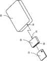
请参阅图1,图1是智能卡、携带型电子装置、及本发明的读卡器其中一实施例的示意图。其中,携带型电子装置30可以是具有上网功能的智能型手机(Smart Phone)(例如苹果公司的iPhone)、平板电脑(Tablet PC)(例如苹果公司的iPad)、或数字多媒体播放器(例如苹果公司的iPod touch)等。携带型电子装置30内含智能卡10相关的应用程序,可通过本发明的读卡器20与智能卡10进行数据交换或处理,并且利用无线网络与远程服务器(未图示出)通讯,进行认证、授权读取和/或修改和/或执行对象等操作。Please refer to FIG. 1 . FIG. 1 is a schematic diagram of an embodiment of a smart card, a portable electronic device, and a card reader of the present invention. Wherein, the portable
由于市售的携带型电子装置都配设有音频传输接口,因此本发明的读卡器20对应设置有一音频传输接口,可利用此音频传输接口与携带型电子装置进行数据传送。在本实施例中,读卡器20的音频传输接口为一整合型声音端子25,将声音的输出及输入整合在同一端子上,可同时输出及输入声音信号。使用时,须先将此声音端子25插入携带型电子装置30的声音插孔35中以完成连接,然后将智能卡10插入读卡器20的插槽26中,即可利用携带型电子装置30的网络功能与远程服务器(未图示出)进行通讯。Since commercially available portable electronic devices are equipped with an audio transmission interface, the
请参阅图2,图2是依据本发明的读卡器的方框图。如图2所示,读卡器20包括一控制电路21、一转换电路22、一升压电路23、一电池24以及一声音端子25。各元件功能分述如下:Please refer to FIG. 2, which is a block diagram of a card reader according to the present invention. As shown in FIG. 2 , the
控制电路21用于控制智能卡10的数据存取,可从智能卡10读出数字数据D1然后传送至转换电路22,或者从转换电路22接收从远程服务器传送来数字数据D2然后写入智能卡10中。The
转换电路22耦接于控制电路21以及声音端子25,用于将数字数据D1转换成模拟声音信号S1然后由声音端子25输出,或者将从声音端子25输入的模拟声音信号S2转换成数字数据D2然后写入智能卡10中。The
升压电路23耦接于控制电路21以及转换电路22,用于提供控制电路21以及转换电路22所需的工作电压。The
电池24经由升压电路23提供电力给控制电路21以及转换电路22。The
声音端子25用于连接携带型电子装置30的声音插孔35,将模拟声音信号S1输出至携带型电子装置30,或者从携带型电子装置30输入模拟声音信号S2。The
请参阅图3,图3是依据本发明的读卡器的转换电路的方框图。如图3所示,转换电路22包括一编码器221、一数字模拟转换器(digital-to-analogconverter)222、一解码器223以及一模拟数字转换器(Analog-to-digitalconverter)224。其中编码器221用于将数字数据D1编辑成既定格式的数字声音信号D3。数字模拟转换器222用于将数字声音信号D3转换成模拟声音信号S1而输出。模拟数字转换器224用于将模拟声音信号S2转换成既定格式的数字声音信号D4。解码器223用于将数字声音信号D4转换成数字数据D2。Please refer to FIG. 3 . FIG. 3 is a block diagram of the conversion circuit of the card reader according to the present invention. As shown in FIG. 3 , the
请参阅图4,图4是携带型电子装置的方框图。为了简洁起见,图中仅显示与本发明相关的主要元件,然而可以了解到,携带型电子装置30可能还包括显示屏幕及其驱动电路、存储器、天线、无线通讯电路等其他元件。Please refer to FIG. 4 , which is a block diagram of the portable electronic device. For the sake of brevity, only the main components related to the present invention are shown in the figure, but it can be understood that the portable
携带型电子装置30包括一声音插孔35、一转换单元32以及一微处理器31,各元件功能分述如下:The portable
声音插孔35用于插接读卡器20的声音端子25,可从读卡器20接收模拟声音信号S1,或者输出模拟声音信号S2至读卡器20。The
转换单元32耦接于声音插孔35以及微处理器31,用于将从声音插孔35输入的模拟声音信号S1还原成从智能卡读出的数字数据D1,或者将远程服务器传来的数字数据D2转换成模拟声音信号S2然后由声音插孔35输出。The
微处理器31处理携带型电子装置30大部分数据及用户输入的操作指令,包括从智能卡10或远程服务器传送来的数字数据D1、D2,将其显示于屏幕所需进行的运算处理,以及执行用户下达指令所需的运算处理等。The
请参阅图5,图5是携带型电子装置的转换单元的方框图。如图5所示,转换单元32包括一模拟数字转换器324、一解码器323、一编码器321以及一数字模拟转换器322。其中模拟数字转换器324将模拟声音信号S1转换成既定格式的数字声音信号D3然后传送至解码器323。解码器323将数字声音信号D3还原成从智能卡读出的数字数据D1。编码器D2从微处理器31接收从远程服务器传送来的数字数据D2并且编辑成既定格式的数字声音信号D4。数字模拟转换器322将数字声音信号D4转换成模拟声音信号S2然后传送至声音插孔35。Please refer to FIG. 5 , which is a block diagram of a conversion unit of a portable electronic device. As shown in FIG. 5 , the converting
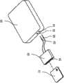
请参阅图6,图6是智能卡、携带型电子装置、及本发明的读卡器另一实施例的示意图。在本实施例中,读卡器20的音频传输接口包括一声音输出端子28以及一声音输入端子29,分别插接于携带型电子装置30的麦克风插孔34以及耳机插孔33上,而将声音信号的输入及输出分开来传送。至于读卡器20的其他元件及功能与前一实施例相同,故省略其说明。Please refer to FIG. 6 . FIG. 6 is a schematic diagram of another embodiment of a smart card, a portable electronic device, and a card reader of the present invention. In this embodiment, the audio transmission interface of the
综上所述,本发明的读卡器能够与携带型电子装置连接而上网,所以即使在室外也能使用智能卡,使用的便利性及机动性大为提高。此外本发明的读卡器采用音频传输接口来传送数据,而市售的携带型电子装置都配设有音频传输接口,所以都能与本发明的读卡器搭配使用。To sum up, the card reader of the present invention can be connected to a portable electronic device to access the Internet, so the smart card can be used even outdoors, and the convenience and mobility of use are greatly improved. In addition, the card reader of the present invention uses an audio transmission interface to transmit data, and commercially available portable electronic devices are equipped with audio transmission interfaces, so they can be used in conjunction with the card reader of the present invention.
以上所列实施方式,虽然是以本发明的读卡器与携带型电子装置连接为例加以说明,然而可以了解到,本发明的读卡器也可以在室内与桌面电脑连接使用,实际上的使用场合并不限于室内或者室外。Although the above-listed embodiments are described by taking the connection between the card reader of the present invention and the portable electronic device as an example, it can be understood that the card reader of the present invention can also be used indoors in connection with a desktop computer. The occasion of use is not limited to indoor or outdoor.
虽然本发明已以优选实施例揭露如上,然而其并非用以限定本发明,任何其所属技术领域的一般技术人员,在不脱离本发明的精神和范围内,应当可以作任意的更动与润饰,因此本发明的保护范围应当以后附的权利要求范围所界定的为准。Although the present invention has been disclosed above with preferred embodiments, it is not intended to limit the present invention. Any person skilled in the art should be able to make any changes and modifications without departing from the spirit and scope of the present invention. , so the scope of protection of the present invention shall prevail as defined by the scope of the appended claims.
Claims (4)
Applications Claiming Priority (2)
| Application Number | Priority Date | Filing Date | Title |
|---|---|---|---|
| TW100210967 | 2011-06-17 | ||
| TW100210967UTWM416151U (en) | 2011-06-17 | 2011-06-17 | Card reader |
Publications (1)
| Publication Number | Publication Date |
|---|---|
| CN102855456Atrue CN102855456A (en) | 2013-01-02 |
Family
ID=46448481
Family Applications (1)
| Application Number | Title | Priority Date | Filing Date |
|---|---|---|---|
| CN2012101673334APendingCN102855456A (en) | 2011-06-17 | 2012-05-25 | card reader |
Country Status (3)
| Country | Link |
|---|---|
| US (1) | US20120320714A1 (en) |
| CN (1) | CN102855456A (en) |
| TW (1) | TWM416151U (en) |
Cited By (1)
| Publication number | Priority date | Publication date | Assignee | Title |
|---|---|---|---|---|
| CN103902492B (en)* | 2014-04-21 | 2017-06-06 | 飞天诚信科技股份有限公司 | A kind of method of work of card reader |
Families Citing this family (3)
| Publication number | Priority date | Publication date | Assignee | Title |
|---|---|---|---|---|
| DE102013103533B4 (en)* | 2013-04-09 | 2018-08-30 | Bundesdruckerei Gmbh | A card reader for reading value and security documents for a computer, a data processing system, and a method for communicating data between a computer and a card reader |
| FR3006134B1 (en) | 2013-05-21 | 2016-12-02 | Cie Ind Et Financiere D'ingenierie Ingenico | METHOD FOR SELF-ADAPTING A SIGNAL QUALITY, CORRESPONDING DEVICES AND COMPUTER PROGRAM |
| JP6206138B2 (en)* | 2013-12-02 | 2017-10-04 | 富士通株式会社 | Storage control device and storage control device control program |
Citations (4)
| Publication number | Priority date | Publication date | Assignee | Title |
|---|---|---|---|---|
| CN1682240A (en)* | 2002-07-30 | 2005-10-12 | 肯尼思·史蒂文·贝利 | Plug-in credit card reader module for wireless cellular phone authentication |
| US20060006230A1 (en)* | 2002-10-16 | 2006-01-12 | Alon Bear | Smart card network interface device |
| US20100314446A1 (en)* | 2009-06-10 | 2010-12-16 | Morley Jr Robert E | Card reader device and method of use |
| US20110084140A1 (en)* | 2009-10-13 | 2011-04-14 | Sam Wen | Systems and methods for decoding card swipe signals |
Family Cites Families (1)
| Publication number | Priority date | Publication date | Assignee | Title |
|---|---|---|---|---|
| US20120052910A1 (en)* | 2010-08-30 | 2012-03-01 | Id Tech | Audio port communication and power device |
- 2011
- 2011-06-17TWTW100210967Upatent/TWM416151U/ennot_activeIP Right Cessation
- 2012
- 2012-05-25CNCN2012101673334Apatent/CN102855456A/enactivePending
- 2012-06-15USUS13/524,320patent/US20120320714A1/ennot_activeAbandoned
Patent Citations (4)
| Publication number | Priority date | Publication date | Assignee | Title |
|---|---|---|---|---|
| CN1682240A (en)* | 2002-07-30 | 2005-10-12 | 肯尼思·史蒂文·贝利 | Plug-in credit card reader module for wireless cellular phone authentication |
| US20060006230A1 (en)* | 2002-10-16 | 2006-01-12 | Alon Bear | Smart card network interface device |
| US20100314446A1 (en)* | 2009-06-10 | 2010-12-16 | Morley Jr Robert E | Card reader device and method of use |
| US20110084140A1 (en)* | 2009-10-13 | 2011-04-14 | Sam Wen | Systems and methods for decoding card swipe signals |
Cited By (1)
| Publication number | Priority date | Publication date | Assignee | Title |
|---|---|---|---|---|
| CN103902492B (en)* | 2014-04-21 | 2017-06-06 | 飞天诚信科技股份有限公司 | A kind of method of work of card reader |
Also Published As
| Publication number | Publication date |
|---|---|
| TWM416151U (en) | 2011-11-11 |
| US20120320714A1 (en) | 2012-12-20 |
Similar Documents
| Publication | Publication Date | Title |
|---|---|---|
| CN202167034U (en) | Peripheral application device and mobile terminal system | |
| US20140379952A1 (en) | Tablet electronic device | |
| US20100243732A1 (en) | Audio/acoustically coupled card reader | |
| CN103493070A (en) | Card reader device using mobile device and method thereof | |
| CN102855456A (en) | card reader | |
| CN102098604A (en) | Mobile phone Bluetooth sound box based on Bluetooth file transfer protocol | |
| CN106504759B (en) | A sound mixing processing method and terminal device | |
| CN113989962B (en) | Access control identification control method and related equipment | |
| WO2014187272A1 (en) | Portable payment device | |
| CN202120288U (en) | Mobile communication terminal having RFID (Radio Frequency Identification) read-write function | |
| CN103167116A (en) | System and method for achieving computer handwriting through screen of mobile phone | |
| CN102647710A (en) | Wireless communication device | |
| CN203288002U (en) | Card reading module and device thereof | |
| CN101222339A (en) | Wireless network card with card reading function | |
| CN201805559U (en) | Electronic photo album based on wireless communication network | |
| CN204270296U (en) | A wireless interconnected mobile memory | |
| CN103632437B (en) | financial authentication device applied to intelligent device | |
| CN203338379U (en) | Card-type read-write equipment based on double-standard audio interface | |
| CN204481913U (en) | The system of CPU card is read based on mobile audio interface | |
| CN204229412U (en) | Hand-held terminal device | |
| CN200986689Y (en) | Wireless mouse | |
| CN201742450U (en) | Mobile phone with A-type USB port | |
| CN202230486U (en) | Intelligent password key device based on wired earphone interface | |
| CN201503599U (en) | Intelligent card and terminal equipment | |
| CN205334633U (en) | Complete machine mainboard and silver -colored advertisement all -in -one of receipts |
Legal Events
| Date | Code | Title | Description |
|---|---|---|---|
| C06 | Publication | ||
| PB01 | Publication | ||
| C10 | Entry into substantive examination | ||
| SE01 | Entry into force of request for substantive examination | ||
| C05 | Deemed withdrawal (patent law before 1993) | ||
| WD01 | Invention patent application deemed withdrawn after publication | Application publication date:20130102 |