CN102854704A - Focus adjustment device and shooting device - Google Patents
Focus adjustment device and shooting deviceDownload PDFInfo
- Publication number
- CN102854704A CN102854704ACN2012102257139ACN201210225713ACN102854704ACN 102854704 ACN102854704 ACN 102854704ACN 2012102257139 ACN2012102257139 ACN 2012102257139ACN 201210225713 ACN201210225713 ACN 201210225713ACN 102854704 ACN102854704 ACN 102854704A
- Authority
- CN
- China
- Prior art keywords
- mentioned
- focus
- optical system
- test section
- detection
- Prior art date
- Legal status (The legal status is an assumption and is not a legal conclusion. Google has not performed a legal analysis and makes no representation as to the accuracy of the status listed.)
- Granted
Links
Images


Classifications
- G—PHYSICS
- G02—OPTICS
- G02B—OPTICAL ELEMENTS, SYSTEMS OR APPARATUS
- G02B7/00—Mountings, adjusting means, or light-tight connections, for optical elements
- G02B7/28—Systems for automatic generation of focusing signals
- G02B7/285—Systems for automatic generation of focusing signals including two or more different focus detection devices, e.g. both an active and a passive focus detecting device
- G—PHYSICS
- G02—OPTICS
- G02B—OPTICAL ELEMENTS, SYSTEMS OR APPARATUS
- G02B7/00—Mountings, adjusting means, or light-tight connections, for optical elements
- G02B7/28—Systems for automatic generation of focusing signals
- G02B7/34—Systems for automatic generation of focusing signals using different areas in a pupil plane
- G02B7/346—Systems for automatic generation of focusing signals using different areas in a pupil plane using horizontal and vertical areas in the pupil plane, i.e. wide area autofocusing
- G—PHYSICS
- G02—OPTICS
- G02B—OPTICAL ELEMENTS, SYSTEMS OR APPARATUS
- G02B7/00—Mountings, adjusting means, or light-tight connections, for optical elements
- G02B7/28—Systems for automatic generation of focusing signals
- G02B7/36—Systems for automatic generation of focusing signals using image sharpness techniques, e.g. image processing techniques for generating autofocus signals
- H—ELECTRICITY
- H04—ELECTRIC COMMUNICATION TECHNIQUE
- H04N—PICTORIAL COMMUNICATION, e.g. TELEVISION
- H04N23/00—Cameras or camera modules comprising electronic image sensors; Control thereof
- H04N23/60—Control of cameras or camera modules
- H04N23/67—Focus control based on electronic image sensor signals
- H04N23/672—Focus control based on electronic image sensor signals based on the phase difference signals
- H—ELECTRICITY
- H04—ELECTRIC COMMUNICATION TECHNIQUE
- H04N—PICTORIAL COMMUNICATION, e.g. TELEVISION
- H04N23/00—Cameras or camera modules comprising electronic image sensors; Control thereof
- H04N23/60—Control of cameras or camera modules
- H04N23/67—Focus control based on electronic image sensor signals
- H04N23/673—Focus control based on electronic image sensor signals based on contrast or high frequency components of image signals, e.g. hill climbing method
- H—ELECTRICITY
- H04—ELECTRIC COMMUNICATION TECHNIQUE
- H04N—PICTORIAL COMMUNICATION, e.g. TELEVISION
- H04N25/00—Circuitry of solid-state image sensors [SSIS]; Control thereof
- H04N25/10—Circuitry of solid-state image sensors [SSIS]; Control thereof for transforming different wavelengths into image signals
- H04N25/11—Arrangement of colour filter arrays [CFA]; Filter mosaics
- H04N25/13—Arrangement of colour filter arrays [CFA]; Filter mosaics characterised by the spectral characteristics of the filter elements
- H04N25/134—Arrangement of colour filter arrays [CFA]; Filter mosaics characterised by the spectral characteristics of the filter elements based on three different wavelength filter elements
- H—ELECTRICITY
- H04—ELECTRIC COMMUNICATION TECHNIQUE
- H04N—PICTORIAL COMMUNICATION, e.g. TELEVISION
- H04N25/00—Circuitry of solid-state image sensors [SSIS]; Control thereof
- H04N25/10—Circuitry of solid-state image sensors [SSIS]; Control thereof for transforming different wavelengths into image signals
- H04N25/11—Arrangement of colour filter arrays [CFA]; Filter mosaics
- H04N25/13—Arrangement of colour filter arrays [CFA]; Filter mosaics characterised by the spectral characteristics of the filter elements
- H04N25/135—Arrangement of colour filter arrays [CFA]; Filter mosaics characterised by the spectral characteristics of the filter elements based on four or more different wavelength filter elements
- H04N25/136—Arrangement of colour filter arrays [CFA]; Filter mosaics characterised by the spectral characteristics of the filter elements based on four or more different wavelength filter elements using complementary colours
- H—ELECTRICITY
- H04—ELECTRIC COMMUNICATION TECHNIQUE
- H04N—PICTORIAL COMMUNICATION, e.g. TELEVISION
- H04N25/00—Circuitry of solid-state image sensors [SSIS]; Control thereof
- H04N25/70—SSIS architectures; Circuits associated therewith
- H04N25/703—SSIS architectures incorporating pixels for producing signals other than image signals
- H04N25/704—Pixels specially adapted for focusing, e.g. phase difference pixel sets
- G—PHYSICS
- G03—PHOTOGRAPHY; CINEMATOGRAPHY; ANALOGOUS TECHNIQUES USING WAVES OTHER THAN OPTICAL WAVES; ELECTROGRAPHY; HOLOGRAPHY
- G03B—APPARATUS OR ARRANGEMENTS FOR TAKING PHOTOGRAPHS OR FOR PROJECTING OR VIEWING THEM; APPARATUS OR ARRANGEMENTS EMPLOYING ANALOGOUS TECHNIQUES USING WAVES OTHER THAN OPTICAL WAVES; ACCESSORIES THEREFOR
- G03B13/00—Viewfinders; Focusing aids for cameras; Means for focusing for cameras; Autofocus systems for cameras
- G03B13/32—Means for focusing
- G03B13/34—Power focusing
- G03B13/36—Autofocus systems
- H—ELECTRICITY
- H04—ELECTRIC COMMUNICATION TECHNIQUE
- H04N—PICTORIAL COMMUNICATION, e.g. TELEVISION
- H04N23/00—Cameras or camera modules comprising electronic image sensors; Control thereof
- H04N23/60—Control of cameras or camera modules
- H04N23/66—Remote control of cameras or camera parts, e.g. by remote control devices
- H04N23/663—Remote control of cameras or camera parts, e.g. by remote control devices for controlling interchangeable camera parts based on electronic image sensor signals
Landscapes
- Physics & Mathematics (AREA)
- Engineering & Computer Science (AREA)
- Multimedia (AREA)
- Signal Processing (AREA)
- General Physics & Mathematics (AREA)
- Optics & Photonics (AREA)
- Spectroscopy & Molecular Physics (AREA)
- Computer Vision & Pattern Recognition (AREA)
- Automatic Focus Adjustment (AREA)
- Studio Devices (AREA)
- Focusing (AREA)
Abstract
Translated fromChinese
Description
Translated fromChinese技术领域technical field
本发明涉及一种焦点调节装置及拍摄装置。The invention relates to a focus adjustment device and a photographing device.
背景技术Background technique
一直以来,下述技术为世人所知:进行光学系统的焦点调节时,为提高焦点调节精度,首先通过相位差检测方式进行光学系统的焦点状态的检测,根据相位差检测方式下的检测结果,将焦点调节用的镜头驱动到对焦位置附近,接着在对焦位置附近,通过对比度检测方式进行光学系统的焦点状态的检测,根据该对比度检测方式下的检测结果,将焦点调节光学系统驱动到对焦位置(例如参照特开2004-109690号公报)。For a long time, following technology is known in the world: when carrying out the focus adjustment of optical system, in order to improve focus adjustment precision, at first carry out the detection of the focus state of optical system by phase difference detection mode, according to the detection result under the phase difference detection mode, Drive the lens for focus adjustment to the vicinity of the focus position, then detect the focus state of the optical system through the contrast detection method near the focus position, and drive the focus adjustment optical system to the focus position according to the detection results in the contrast detection method (For example, refer to JP-A-2004-109690).
发明内容Contents of the invention
但是,上述专利文献1中,其前提是通过相位差检测方式及对比度检测方式两种方式可进行光学系统的焦点检测,因此,在通过相位差检测方式及对比度检测方式中的任意一个方式无法进行焦点检测的拍摄场景中,存在无法良好地进行焦点调节的情况。并且,在上述专利文献1中,首先进行相位差检测方式下的焦点检测,接着进行对比度检测方式下的焦点检测,因此存在焦点调节耗时的问题。However, in the above-mentioned
本发明要解决的问题是提供一种可适当进行焦点调节的焦点调节装置。The problem to be solved by the present invention is to provide a focus adjusting device which can properly adjust the focus.
本发明通过以下解决方法解决上述课题。此外,以下对表示本发明的实施方式的附图附加对应的附图标记进行说明,但该附图标记仅用于易于理解发明,并不限定发明。The present invention solves the above-mentioned problems by the following solutions. In addition, although the corresponding code|symbol is attached|subjected to the drawing which shows embodiment of this invention and demonstrates below, this code|symbol is only for easy understanding of invention, and does not limit invention.
本发明的第1观点涉及的焦点调节装置的特征在于具有:第1检测部(221),通过对比度检测方式检测焦点状态;第2检测部(222a、222b),通过相位差检测方式检测焦点状态;控制部(21),控制上述第1检测部及上述第2检测部,使得在进行上述第1检测部对焦点状态的检测时,进行上述第2检测部对焦点状态的检测。The focus adjustment device according to the first aspect of the present invention is characterized by comprising: a first detection unit (221) that detects a focus state by a contrast detection method; and a second detection unit (222a, 222b) that detects a focus state by a phase difference detection method A control unit (21) controlling the first detection unit and the second detection unit so that when the first detection unit detects the focus state, the second detection unit detects the focus state.
在上述焦点调节装置涉及的发明中,可如下构成:进一步具有:拍摄部(22),拍摄具有焦点调节光学系统(32)的光学系统形成的图像,输出和拍摄的图像对应的图像信号;焦点调节部(36),向上述焦点调节光学系统的光轴方向驱动上述焦点调节光学系统,调节上述光学系统的焦点状态,上述第1检测部(221)根据通过上述拍摄部输出的上述图像信号,算出与上述光学系统形成的图像的对比度相关的评估值,从而检测上述光学系统的焦点状态,上述第2检测部(222a、222b)设置在上述拍摄部的受光面上,在上述拍摄部进行上述图像的拍摄过程中,使用相位差检测上述光学系统的焦点状态,上述控制部(21)使上述第1检测部对焦点状态的检测及上述第2检测部对焦点状态的检测为可能状态。In the invention related to the above-mentioned focus adjustment device, it may be configured as follows: further comprising: an imaging unit (22), which captures an image formed by an optical system having a focus adjustment optical system (32), and outputs an image signal corresponding to the captured image; An adjustment unit (36) drives the focus adjustment optical system in the direction of the optical axis of the focus adjustment optical system to adjust the focus state of the optical system, and the first detection unit (221) based on the image signal output by the imaging unit, Calculate the evaluation value related to the contrast of the image formed by the above-mentioned optical system, so as to detect the focus state of the above-mentioned optical system. During image capture, the focus state of the optical system is detected using a phase difference, and the control unit (21) enables detection of the focus state by the first detection unit and detection of the focus state by the second detection unit.
在上述焦点调节装置涉及的发明中,可如下构成:上述控制部(21)在通过上述第2检测部(222a、222b)无法进行上述光学系统的焦点状态的检测时,使上述第1检测部(221)对焦点状态的检测及上述第2检测部对焦点状态的检测为可能状态。In the invention related to the above-mentioned focus adjustment device, the control unit (21) may be configured as follows: when the second detection unit (222a, 222b) cannot detect the focus state of the optical system, the first detection unit (221) The detection of the state of the focus point and the detection of the state of the focus point by the second detection unit are enabled.
在上述焦点调节装置涉及的发明中,可如下构成:上述控制部(21)通过使上述焦点调节部(36)进行上述焦点调节光学系统(32)的扫描驱动,从而使上述第1检测部(221)对焦点状态的检测及上述第2检测部(222a、222b)对焦点状态的检测为可能状态。In the invention pertaining to the focus adjustment device, the control unit (21) may be configured as follows: the control unit (21) causes the focus adjustment unit (36) to scan and drive the focus adjustment optical system (32), so that the first detection unit ( 221) The detection of the state of the focus point and the detection of the state of the focus point of the second detection unit (222a, 222b) are enabled.
在上述焦点调节装置涉及的发明中,可如下构成:上述控制部(21)使用上述第1检测部(221)及上述第2检测部(222a、222b)中的、先进行上述光学系统(31、32、33)的焦点状态检测的一方的检测结果,使上述焦点调节部(36)进行向上述焦点调节光学系统(32)的对焦位置的驱动。In the invention related to the above-mentioned focus adjustment device, it may be configured as follows: the control unit (21) uses the first detection unit (221) and the second detection unit (222a, 222b) to perform the above-mentioned optical system (31 , 32, 33) detection results of one of the focus state detections causes the focus adjustment unit (36) to drive to the focus position of the focus adjustment optical system (32).
在上述焦点调节装置涉及的发明中,可如下构成:上述控制部(21)在通过上述第2检测部(222a、222b)无法进行上述光学系统(31、32、33)的焦点状态的检测时,使上述第1检测部(221)进行上述光学系统的焦点状态的检测。In the invention related to the focus adjustment device, the control unit (21) may be configured as follows: when the second detection unit (222a, 222b) cannot detect the focus state of the optical system (31, 32, 33) , causing the first detection unit (221) to detect the focus state of the optical system.
在上述焦点调节装置涉及的发明中,可如下构成:上述控制部(21)在通过上述第2检测部(222a、222b)可进行上述光学系统(31、32、33)的焦点状态的检测时,根据上述第2检测部的检测结果,使上述焦点调节部(36)进行向上述焦点调节光学系统(32)的对焦位置的驱动。In the invention related to the focus adjustment device, the control unit (21) may be configured as follows: when the control unit (21) can detect the focus state of the optical system (31, 32, 33) through the second detection unit (222a, 222b) The focus adjustment unit (36) is driven to a focus position of the focus adjustment optical system (32) based on a detection result of the second detection unit.
在上述焦点调节装置涉及的发明中,可如下构成:上述控制部(21)在通过上述第2检测部(222a、222b)无法进行上述光学系统的焦点状态的检测时,使上述焦点调节部(36)进行上述焦点调节光学系统(32)的扫描驱动的同时,进行上述第1检测部(221)对焦点状态的检测及上述第2检测部对焦点状态的检测。In the invention related to the above-mentioned focus adjustment device, the control unit (21) may be configured as follows: when the focus state of the optical system cannot be detected by the second detection unit (222a, 222b), the focus adjustment unit ( 36) Simultaneously with the scanning drive of the focus adjustment optical system (32), the detection of the focus state of the first detection unit (221) and the detection of the focus state of the second detection unit are performed.
本发明的第2观点涉及的焦点调节装置的特征在于具有:第1检测部(221),通过对比度检测方式检测焦点状态;第2检测部(222a、222b),通过相位差检测方式检测焦点状态;控制部(21),进行控制,使得向通过上述第1检测部检测出的位置驱动焦点调节光学系统(32)时,禁止向通过上述第2检测部检测出的位置驱动上述焦点调节光学系统。The focus adjustment device according to the second viewpoint of the present invention is characterized by comprising: a first detection unit (221) that detects a focus state by a contrast detection method; and a second detection unit (222a, 222b) that detects a focus state by a phase difference detection method The control unit (21) controls such that when the focus adjustment optical system (32) is driven to the position detected by the first detection unit, it is prohibited to drive the focus adjustment optical system to the position detected by the second detection unit .
在上述焦点调节装置涉及的发明中,可如下构成:进一步具有:拍摄部(22),拍摄具有上述焦点调节光学系统(32)的光学系统形成的图像,输出和拍摄的图像对应的图像信号;焦点调节部(36),向上述焦点调节光学系统的光轴方向驱动上述焦点调节光学系统(32),调节上述光学系统的焦点状态,上述第1检测部(221)根据通过上述拍摄部输出的上述图像信号,算出上述光学系统形成的图像的对比度相关的评估值,从而检测上述光学系统的焦点状态,上述第2检测部(222a、222b)在上述拍摄部进行上述图像的拍摄过程中,使用相位差检测上述光学系统的焦点状态,上述控制部(21)在基于上述第1检测部的检测结果的上述焦点调节光学系统的驱动完成为止,禁止基于上述第2检测部的检测结果的上述焦点调节光学系统的驱动。In the invention related to the above-mentioned focus adjustment device, it may be configured as follows: further comprising: an imaging unit (22), which captures an image formed by the optical system having the above-mentioned focus adjustment optical system (32), and outputs an image signal corresponding to the captured image; The focus adjustment unit (36) drives the focus adjustment optical system (32) in the direction of the optical axis of the focus adjustment optical system to adjust the focus state of the optical system, and the first detection unit (221) outputs The image signal is used to calculate the evaluation value related to the contrast of the image formed by the optical system, thereby detecting the focus state of the optical system. The second detection unit (222a, 222b) uses The phase difference detects the focus state of the optical system, and the control unit (21) prohibits the focus adjustment based on the detection result of the second detection unit until the drive of the focus adjustment optical system based on the detection result of the first detection unit is completed. Adjust the drive of the optical system.
在上述焦点调节装置涉及的发明中,可如下构成:上述控制部(21)在基于上述第1检测部(221)的检测结果的上述焦点调节光学系统(32)的驱动完成后,在经过规定时间后,允许基于上述第2检测部(222a、222b)的检测结果的上述焦点调节光学系统的驱动。In the invention related to the focus adjustment device, the control unit (21) may be configured as follows: after the drive of the focus adjustment optical system (32) based on the detection result of the first detection unit (221) is completed, After a period of time, the drive of the focus adjustment optical system based on the detection result of the second detection unit (222a, 222b) is permitted.
在上述焦点调节装置涉及的发明中,可如下构成:进一步具有向用户报告对焦的报告部(25、26),上述控制部(21)在基于上述第1检测部(221)的检测结果的上述焦点调节光学系统(32)的驱动完成后,在上述报告部报告之后,允许基于上述第2检测部(222a、222b)的检测结果的上述焦点调节光学系统的驱动。In the invention related to the above-mentioned focus adjustment device, it may be configured as follows: a report unit (25, 26) that reports focus to the user is further provided, and the control unit (21) performs the above-mentioned After the drive of the focus adjustment optical system (32) is completed, the drive of the focus adjustment optical system based on the detection result of the second detection unit (222a, 222b) is allowed after the reporting unit reports.
在上述焦点调节装置涉及的发明中,可如下构成:上述控制部(21)在基于上述第1检测部(221)的检测结果的上述焦点调节光学系统(32)的驱动完成为止,禁止上述第2检测部(222a、222b)对上述光学系统(31、32、33)的焦点状态的检测。In the invention related to the focus adjustment device, the control unit (21) may be configured to prohibit the first focus adjustment optical system (32) from being driven until the drive of the focus adjustment optical system (32) based on the detection result of the first detection unit (221) is completed. 2. The detection unit (222a, 222b) detects the focus state of the optical system (31, 32, 33).
在上述焦点调节装置涉及的发明中,可如下构成:上述控制部(21)在通过上述第1检测部(221)检测出对焦位置的情况下,也允许上述第2检测部(222a、222b)对上述光学系统(31、32、33)的焦点状态的检测。In the invention related to the focus adjustment device, the control unit (21) may allow the second detection unit (222a, 222b) to detect the focus position by the first detection unit (221). Detection of the focus state of the above-mentioned optical system (31, 32, 33).
在上述焦点调节装置涉及的发明中,可如下构成:上述第2检测部(222a、222b)设置在上述拍摄部(22)的受光面上。In the invention related to the above-mentioned focus adjustment device, it may be configured that the second detection unit (222a, 222b) is provided on the light receiving surface of the imaging unit (22).
在上述焦点调节装置涉及的发明中,可如下构成:上述控制部(21)在通过上述第2检测部(222a、222b)无法检测出对焦位置时,使上述第1检测部(221)进行对上述光学系统(31、32、33)的焦点状态的检测。In the invention related to the above-mentioned focus adjustment device, the control unit (21) may be configured to make the first detection unit (221) perform a comparison when the focus position cannot be detected by the second detection unit (222a, 222b). Detection of the focus state of the above-mentioned optical system (31, 32, 33).
本发明的第3观点涉及的焦点调节装置的特征在于具有:检测部(221、222a、222b),驱动焦点调节光学系统(32)通过对比度检测方式进行焦点评估值的检测时,可通过相位差检测方式检测焦点状态;控制部(21),进行控制,在以比规定速度慢的第1速度驱动上述焦点调节光学系统从而检测出上述焦点评估值的峰值时,将上述焦点调节光学系统驱动到与上述峰值对应的位置,在以比规定速度快的第2速度驱动上述焦点调节光学系统从而检测上述焦点评估值的峰值时,不将上述焦点调节光学系统驱动到与上述峰值对应的位置,以比上述规定速度慢的速度驱动上述焦点调节光学系统,从而检测上述焦点评估值的峰值。The focus adjustment device according to the third aspect of the present invention is characterized by having a detection unit (221, 222a, 222b) that drives the focus adjustment optical system (32) to detect the focus evaluation value by the contrast detection method, which can be detected by the phase difference The detection method detects the focus state; the control unit (21) controls the focus adjustment optical system to be driven to At the position corresponding to the peak value, when the focus adjustment optical system is driven at a second speed faster than a predetermined speed to detect the peak value of the focus evaluation value, the focus adjustment optical system is not driven to the position corresponding to the peak value, so that The focus adjustment optical system is driven at a speed slower than the predetermined speed to detect the peak value of the focus evaluation value.
在上述焦点调节装置涉及的发明中,可如下构成:进一步具有:拍摄部(22),拍摄具有上述焦点调节光学系统的光学系统(31、32、33)形成的图像,输出和拍摄的图像对应的图像信号;焦点调节部(36),向上述焦点调节光学系统的光轴方向驱动上述焦点调节光学系统(32),使上述光学系统的图像面以规定的移动速度移动,从而调节上述光学系统的焦点状态,上述检测部具有:第1检测部(221),根据通过上述拍摄部输出的上述图像信号,算出上述光学系统形成的图像的对比度相关的评估值,从而进行上述对比度检测方式下的焦点状态的检测;第2检测部(222a、222b),在上述拍摄部对上述图像的拍摄过程中,使用相位差检测上述光学系统的焦点状态,从而进行上述相位差检测方式下的焦点状态的检测,上述控制部(21),使上述焦点调节部驱动上述焦点调节光学系统,从而形成可进行上述第1检测部对焦点状态的检测及上述第2检测部对焦点状态的检测的状态,当检测出上述评估值的峰值时的上述图像面的移动速度大于上述规定速度时,将上述图像面的移动速度变更为上述规定速度以下,当上述图像面的移动速度是上述规定速度以下时,使上述焦点调节光学系统驱动到上述评估值变为峰值的位置。In the invention related to the aforementioned focus adjustment device, it may be configured as follows: further comprising: an imaging unit (22), which captures images formed by the optical system (31, 32, 33) having the aforementioned focus adjustment optical system, and outputs images corresponding to the captured images image signal; the focus adjustment unit (36) drives the focus adjustment optical system (32) in the direction of the optical axis of the focus adjustment optical system, so that the image plane of the above optical system moves at a prescribed moving speed, thereby adjusting the above optical system The focus state of the above-mentioned detection unit includes: a first detection unit (221), which calculates an evaluation value related to the contrast of the image formed by the above-mentioned optical system based on the above-mentioned image signal output by the above-mentioned imaging unit, so as to perform the above-mentioned contrast detection mode. Detection of the focus state; the second detection part (222a, 222b), during the process of the above-mentioned image shooting by the above-mentioned shooting part, uses phase difference to detect the focus state of the above-mentioned optical system, so as to perform the detection of the focus state in the above-mentioned phase difference detection method detection, the control unit (21) causes the focus adjustment unit to drive the focus adjustment optical system, thereby forming a state where the detection of the focus state of the first detection unit and the detection of the focus state of the second detection unit are possible, when When the moving speed of the image plane when the peak value of the evaluation value is detected is greater than the predetermined speed, the moving speed of the image plane is changed to be equal to or lower than the predetermined speed, and when the moving speed of the image plane is equal to or lower than the predetermined speed, the The above-mentioned focus adjustment optical system is driven to a position where the above-mentioned evaluation value becomes a peak value.
在上述焦点调节装置涉及的发明中,可如下构成:上述控制部(21)在将上述图像面的移动速度变更为上述规定速度以下的速度时,在通过上述第1检测部(221)检测出了上述评估值的峰值时,使上述焦点调节光学系统(32)驱动到上述评估值变为峰值的位置。In the invention related to the above-mentioned focus adjustment device, the control unit (21) may be configured such that when the moving speed of the image plane is changed to a speed equal to or lower than the predetermined speed, the first detection unit (221) detects When the peak value of the evaluation value is reached, the focus adjustment optical system (32) is driven to a position where the evaluation value reaches the peak value.
在上述焦点调节装置涉及的发明中,可如下构成:上述控制部(21)在将上述图像面的移动速度变更为上述规定速度以下的速度时,在通过上述第2检测部(222a、222b)检测出了对焦位置时,使上述焦点调节光学系统(32)驱动到上述对焦位置。In the invention related to the above-mentioned focus adjustment device, the control unit (21) may be configured as follows: When the focus position is detected, the focus adjustment optical system (32) is driven to the focus position.
在上述焦点调节装置涉及的发明中,可如下构成:上述第2检测部(222a、222b)设置在上述拍摄部(22)的受光面上。In the invention related to the above-mentioned focus adjustment device, it may be configured that the second detection unit (222a, 222b) is provided on the light receiving surface of the imaging unit (22).
在上述焦点调节装置涉及的发明中,可如下构成:进一步具有存储部(38),其将通过上述第1检测部(221)可检测出对焦位置的图像面移动速度中最快的速度,作为焦点检测可能速度预先存储,上述控制部(21)使用上述焦点检测可能速度作为上述规定速度。In the invention pertaining to the above-mentioned focus adjustment device, it may be configured as follows: further comprising a storage unit (38) that uses the fastest speed among image plane movement speeds that can detect the focus position by the first detection unit (221) as A focus detection possible speed is stored in advance, and the control unit (21) uses the focus detection possible speed as the predetermined speed.
在上述焦点调节装置涉及的发明中,可如下构成:上述控制部(21)在通过上述第2检测部(222a、222b)无法检测出对焦位置时,使上述第1检测部(221)进行上述光学系统的焦点状态的检测。In the invention related to the above-mentioned focus adjustment device, the control unit (21) may cause the first detection unit (221) to perform the above-mentioned Detection of the focus state of the optical system.
本发明涉及的拍摄装置的特征在于,具有上述焦点调节装置。An imaging device according to the present invention includes the above-mentioned focus adjustment device.
根据本发明,可适当进行焦点调节。According to the present invention, focus adjustment can be appropriately performed.
附图说明Description of drawings
图1是表示本实施方式涉及的数字相机1的框图。FIG. 1 is a block diagram showing a
图2是表示图1所示的拍摄元件的拍摄面中的焦点检测位置的正面图。FIG. 2 is a front view showing a focus detection position on an imaging surface of the imaging element shown in FIG. 1 .
图3是放大图2的III部以示意示出焦点检测像素222a、222b的排列的正面图。FIG. 3 is a front view schematically showing the arrangement of
图4是放大图2的IV部以示意示出焦点检测像素222a、222b的排列的正面图。FIG. 4 is a front view schematically showing the arrangement of
图5是放大表示拍摄像素221的一个的正面图。FIG. 5 is an enlarged front view showing one of the
图6(A)是放大表示焦点检测像素222a的一个的正面图,图6(B)是放大表示焦点检测像素222b的一个的正面图。6(A) is an enlarged front view showing one of the
图7是放大表示拍摄像素221的一个的截面图。FIG. 7 is an enlarged cross-sectional view showing one of the
图8(A)是放大表示焦点检测像素222a的一个的截面图,图8(B)是放大表示焦点检测像素222b的一个的截面图。8(A) is an enlarged cross-sectional view showing one of the
图9是表示对三个拍摄像素RGB各自的波长的相对灵敏度的分光特性图。FIG. 9 is a spectral characteristic diagram showing relative sensitivities to respective wavelengths of three imaging pixels RGB.
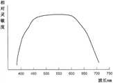
图10是表示对焦点检测像素的波长的相对灵敏度的分光特性图。FIG. 10 is a spectral characteristic diagram showing relative sensitivity to wavelength of a focus detection pixel.
图11是沿着图3及图4的XI-XI线的截面图。Fig. 11 is a cross-sectional view taken along line XI-XI in Figs. 3 and 4 .
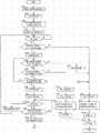
图12是表示第1实施方式涉及的相机的动作示例的流程图。FIG. 12 is a flowchart showing an example of the operation of the camera according to the first embodiment.
图13是表示本实施方式涉及的搜索动作中的、聚焦镜头位置和焦点评估值的关系、及聚焦镜头位置和时间的关系的图。13 is a diagram showing the relationship between the focus lens position and the focus evaluation value, and the relationship between the focus lens position and time in the search operation according to the present embodiment.
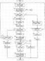
图14是表示第2实施方式涉及的相机的动作示例的流程图。14 is a flowchart showing an example of the operation of the camera according to the second embodiment.
图15是表示第3实施方式涉及的相机的动作示例的流程图。FIG. 15 is a flowchart showing an example of the operation of the camera according to the third embodiment.
图16是表示第4实施方式涉及的相机的动作示例的流程图。FIG. 16 is a flowchart showing an example of the operation of the camera according to the fourth embodiment.
图17是表示第1扫描动作中的、聚焦镜头位置和焦点评估值的关系、及聚焦镜头位置和时间的关系的图。17 is a diagram showing the relationship between the focus lens position and the focus evaluation value, and the relationship between the focus lens position and time in the first scanning operation.
图18是表示第2扫描动作及第3扫描动作中的、聚焦镜头位置和焦点评估值的关系、及聚焦镜头位置和时间的关系的图。18 is a diagram showing the relationship between the focus lens position and focus evaluation value, and the relationship between the focus lens position and time in the second scanning operation and the third scanning operation.
具体实施方式Detailed ways
以下根据附图说明本发明的实施方式。Embodiments of the present invention will be described below with reference to the drawings.
(第1实施方式)(first embodiment)
图1是表示本发明的实施方式涉及的数字相机1的要部构成图。本实施方式的数字相机1(以下简称为相机1)由相机主体2和镜头镜筒3构成,该相机主体2和镜头镜筒3通过卡口部4可装卸地结合。FIG. 1 is a configuration diagram showing a main part of a
镜头镜筒3是可装卸到相机主体2的交换镜头。如图1所示,镜头镜筒3中内置包括镜头31、32、33及光圈34的拍摄光学系统。The lens barrel 3 is an interchangeable lens that can be attached to and detached from the
镜头32是聚焦镜头,通过向光轴L1方向移动,可调节拍摄光学系统的焦点距离。聚焦镜头32设置为沿着镜头镜筒3的光轴L1可移动,通过编码器35检测出其位置的同时,通过聚焦镜头驱动电机36调节其位置。The
沿着该聚焦镜头32的光轴L1的移动机构的具体构成没有特别限定。列举一例:将旋转筒可旋转地插入到固定在镜头镜筒3上的固定筒中,在该旋转筒的内周面上形成螺旋槽,并且使固定聚焦镜头32的镜头框的端部嵌合到螺旋槽。并且,通过聚焦镜头驱动电机36使旋转筒旋转,从而使镜头框上固定的聚焦镜头32沿着光轴L1直行移动。The specific configuration of the movement mechanism along the optical axis L1 of the
如上所述,通过使旋转筒相对镜头镜筒31旋转,镜头框上固定的聚焦镜头32在光轴L1方向上直行移动,但作为其驱动源的聚焦镜头驱动电机36设置在镜头镜筒3上。聚焦镜头驱动电机36和旋转筒例如通过由多个齿轮构成的变速机连接,将聚焦镜头驱动电机36的驱动轴向任意一个方向旋转驱动时,以规定的齿轮比传送到旋转筒,并且,通过旋转筒向任意一个方向旋转,镜头框上固定的聚焦镜头32向光轴L1的任意一个方向直行移动。此外,当聚焦镜头驱动电机36的驱动轴逆向旋转驱动时,构成变速机的多个齿轮也逆向旋转,聚焦镜头32向光轴L1的逆向直行移动。As described above, by rotating the rotary barrel relative to the
聚焦镜头32的位置通过编码器35检测。如上所述,聚焦镜头32的光轴L1方向的位置与旋转筒的旋转角度相关,因此例如检测出旋转筒相对镜头镜筒3的旋转角度就可求出。The position of the
作为本实施方式的编码器35可使用:通过光斩波器等光传感器检测与旋转筒的旋转驱动连接的旋转圆板的旋转,输出和旋转次数对应的脉冲信号的装置;对设置在固定筒和旋转筒中的任意一个的柔性印刷布线板表面的编码图案,接触设置在任意另一个上的电刷接点,通过检测电路检测和旋转筒的移动量(可以是旋转方向、光轴方向的任意一个)对应的接触位置的变化的装置等。As the
聚焦镜头32通过上述旋转筒的旋转,在相机机身侧的端部(也称为广角端)到被摄体侧的端部(也称为长焦端)之间,可向光轴L1方向移动。此外,通过编码器35检测出的聚焦镜头32的当前位置信息经由镜头控制部37发送到下述相机控制部21,聚焦镜头驱动电机36如下驱动:根据该信息计算的聚焦镜头32的驱动位置从相机控制部21经由镜头控制部37送出。The
并且,在本实施方式中,镜头控制部37根据相机控制部21的指示,为使聚焦镜头37以规定的镜头驱动速度驱动,将和镜头驱动速度对应的驱动脉冲信号发送到聚焦镜头驱动电机36。并且,镜头控制部37在镜头控制部37具有的存储器38中存储下述聚焦镜头32的焦点可检测最大速度Vmax。In addition, in the present embodiment, the lens control unit 37 transmits a drive pulse signal corresponding to the lens drive speed to the focus
光圈34使以光轴L1为中心的开口直径可调节地构成,以限制通过上述拍摄光学系统到达拍摄元件22的光束的光量,并且调整光晕量。光圈34对开口直径的调节例如如下进行:在自动曝光模式中计算出的适当的开口直径从相机控制部21经由镜头控制部37送出。并且,通过设置在相机主体2的操作部28的手动操作,设定的开口直径从相机控制部21输入到镜头控制部37。光圈34的开口直径由未图示的光圈开口传感器检测,通过镜头控制部37识别当前的开口直径。The
另一方面,相机主体2中,接受来自上述拍摄光学系统的光束L1的拍摄元件22设置在拍摄光学系统的预定焦点面上,在其前面设置快门23。拍摄元件22由CCD等设备构成,将接收的光信号变换为电信号,送出到相机控制部21。送出到相机控制部21的拍摄图像信息逐个送出到液晶驱动电路25,显示在观察光学系统的电子取景器(EVF)26中,并且当操作部28具有的释放键(未图示)被完全下压时,该拍摄图像信息记录到作为记录介质的存储器24中。存储器24可使用可装卸的卡片型存储器、内置型存储器的任意一种。此外,在拍摄元件22的拍摄面的前方配置:用于切断红外线的红外线截止滤波器、及用于防止图像重叠(折返し)噪点的光学低通滤波器。稍后详述拍摄元件22的构造。On the other hand, in the
相机主体2上设置用于观察通过拍摄元件22拍摄的图像的观察光学系统。本实施方式的观察光学系统具有:由液晶显示元件构成的电子取景器(EVF)26;驱动它的液晶驱动电路25;目镜27。液晶驱动电路25读入由拍摄元件22拍摄、并送出到相机控制部21的拍摄图像信息,据此驱动电子取景器26。由此,用户可通过目镜27观察当前的拍摄图像。此外,也可替代光轴L2形成的上述观察光学系统,或者除此以外将液晶显示器设置在相机主体2的背面等,可在该液晶显示器上显示拍摄图像。The
在相机主体2上设置相机控制部21。相机控制部21通过设置在卡口部4上的电信号接点部41与镜头控制部37电连接,从该镜头控制部37接收镜头信息,并且向镜头控制部37发送散焦量、光圈开口直径等信息。并且,相机控制部21如上所述,从拍摄元件22读出像素输出,并且对读出的像素输出根据需要实施规定的信息处理,从而生成图像信息,将生成的图像信息输出到电子取景器26的液晶驱动电路25、存储器24。并且,相机控制部21主管校正来自拍摄元件22的图像信息、检测镜头镜筒3的焦点调节状态、光圈调节状态等的对相机1整体的控制。A
并且,相机控制部21除此以外,根据从拍摄元件22读出的像素数据,进行相位检测方式下的拍摄光学系统的焦点状态的检测、及对比度检测方式下的光学拍摄系统的焦点状态的检测。此外,稍后论述具体的焦点状态的检测方法。In addition, the
操作部28是快门释放键、用户用于设定相机1的各种动作模式的输入开关,可进行自动聚焦模式/手动聚焦模式的切换,在自动聚焦模式中,可进行单拍模式/连拍模式的切换。其中,单拍模式是指,固定一次调节的聚焦镜头32的位置,在该聚焦镜头位置下进行拍摄的模式,与之相对,连拍模式是指,不固定聚焦镜头32的位置,对应被摄体调节聚焦镜头位置的模式。通过该操作部28设定的各种模式送出到相机控制部21,通过该相机控制部21控制相机1整体的动作。并且,快门释放键包括:通过按钮的半下压接通的第1开关SW1;通过按钮的完全下压接通的第2开关SW2。The
接着说明本实施方式涉及的拍摄元件22。Next, the
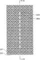
图2是表示拍摄元件22的拍摄面的正面图,图3是放大图2的Ⅲ部表示焦点检测像素222a、222b的排列的示意正面图,图4是放大图2的IV部表示焦点检测像素222a、222b的排列的示意正面图。FIG. 2 is a front view showing the imaging surface of the
本实施方式的拍摄元件22如图3及图4所示,多个拍摄像素221在拍摄面的平面上二维排列,具有透过绿色波长区域的彩色滤波器的绿像素G、具有透过红色波长区域的彩色滤波器的红像素R、具有透过蓝色波长区域的彩色滤波器的蓝像素B,进行所谓拜耳排列(BayerArrangement)。即,在邻接的4个像素组223(稠密正方格排列)中,在一个对角线上排列2个绿像素,在另一个对角线上各排列一个红像素和蓝像素。以该拜耳排列的像素组223为单位,将该像素组223在拍摄元件22的拍摄面上二维状反复排列,从而构成拍摄元件22。In the
此外,单位像素组223的排列除了图示的稠密正方格以外,例如也可稠密六方格排列。并且,彩色滤波器的构成、排列不限于此,也可采用补色滤波器(绿:G,黄:Ye,洋红:Mg,蓝绿Cy)的排列。In addition, the arrangement of the
图5是放大拍摄像素221的一个的正面图,图7是截面图。一个拍摄像素221由微型镜头2211、光电变换部2212、未图示的彩色滤波器构成,如图7的截面图所示,在拍摄元件22的半导体电路基板2213的表面植入光电变换部2212,在其表面形成微型镜头2211。光电变换部2212是接受通过微型镜头2211经过拍摄光学系统的射出光瞳(例如F1.0)的拍摄光束的形状,接受拍摄光束。FIG. 5 is an enlarged front view of one of the
此外,本实施方式的彩色滤波器设置在微型镜头2211和光电变换部2212之间,绿像素G和红像素R及蓝像素B各自的彩色滤波器的分光灵敏度例如如图9所示。图9是表示对图3及图4所示的3个拍摄像素RGB各自的波长的相对灵敏度的分光特性图。In addition, the color filter of this embodiment is provided between the
返回到图2,在拍摄元件22的拍摄面的中心、及从中心到上下及左右对称位置的5个地方,设置替代上述拍摄像素221而排列焦点检测像素222a、222b的焦点检测像素列22a、22b、22c、22d、22e。并且,如图3、图4所示,一个焦点检测像素列如下构成:多个焦点检测像素222a及222b彼此邻接,交互地横一列(22a、22d、22e)或纵一列(22b、22c)排列。在本实施方式中,焦点检测像素222a及222b在拜耳排列的拍拍摄素221的绿像素G和蓝像素B的位置处,不设置间隙地紧密排列。Returning to FIG. 2 , in the center of the imaging surface of the
此外,图2所示的焦点检测像素列22a~22e的位置不仅限于图示的位置,也可是一个、两个或三个位置等,并且也可配置在六个以上的位置处。并且,在实际进行焦点检测时,从多个配置的焦点检测像素列22a~22e中,用户可通过手动操作操作部28,将所需的焦点检测像素列作为焦点检测位置选择。In addition, the positions of the focus
图6(A)是表示放大焦点检测像素222a的一个的正面图,图8(A)是焦点检测像素222a的截面图。并且,图6(B)是表示放大焦点检测像素222b的一个的正面图,图8(B)是焦点检测像素222b的截面图。焦点检测像素222a如图6(A)所示,由微型镜头2221a、半圆形状的光电变换部2222a构成,如图8(A)的截面图所示,在拍摄元件22的半导体电路基板2213的表面植入光电变换部2222a,在其表面形成微型镜头2221a。并且,焦点检测像素222b如图6(B)所示,由微型镜头2221b、光电变换部2222b构成,如图8(B)的截面图所示,在拍摄元件22的半导体电路基板2213的表面植入光电变换部2222b,在其表面形成微型镜头2221b。并且,该焦点检测像素222a及222b如图3、图4所示,彼此邻接,交互地横一列或纵一列排列,从而构成图2所示的焦点检测像素列22a~22e。FIG. 6(A) is a front view showing an enlarged
此外,焦点检测像素222a、222b的光电变换部2222a、2222b是接受通过微型镜头2221a、2221b经过拍摄光学系统的射出光瞳的规定区域(例如F2.8)的光束的形状。并且,焦点检测像素222a、222b上不设置彩色滤波器,其分光特性综合了进行光电变换的光电二极管的分光特性、及未图示的红外线滤波器的分光特性。图10表示焦点检测像素222a、222b的分光特性,相对灵敏度是加算了图9所示的拍摄像素221的蓝像素B、绿像素G及红像素R的各灵敏度的分光特性,并且具有灵敏度的光波长区域是包括拍摄像素221的蓝像素B、绿像素G及红像素R的灵敏度的光波长区域的区域。其中,也可构成为具有与拍摄像素221相同的彩色滤波器中的一个、例如绿滤波器地构成。此外,图10是表示对图3及图4所示的焦点检测像素的波长的相对灵敏度的分光特性图。In addition, the
并且,图6(A)、图6(B)所示的焦点检测像素222a、222b的光电变换部2222a、2222b是半圆形状,但光电变换部2222a、2222b的形状不限于此,也可是其他形状,例如是椭圆形、矩形、多角形。In addition, the
在此说明根据上述焦点检测像素222a、222b的像素输出检测拍摄光学系统的焦点状态的、所谓相位差检测方式。Here, a so-called phase difference detection method for detecting the focus state of the imaging optical system based on the pixel outputs of the above-mentioned
图11是沿着图3及图的XI-XI的截面图,表示配置在拍摄光轴L1附近、彼此邻接的焦点检测像素222a-1、222b-1、222a-2、222b-2分别接收从射出光瞳350的测距光瞳351、352照射的光束AB 1-1、AB2-1、AB1-2、AB2-2。此外,在图11中,仅示例了多个焦点检测像素222a、222b中,位于拍摄光轴L1附近的情况,但图11所示的焦点检测像素以外的其他焦点检测像素也同样构成为分别接受从一对测距光瞳351、352照射的光束。FIG. 11 is a cross-sectional view along FIG. 3 and XI-XI of the figure, showing that the
其中,射出光瞳350是设定在拍摄光学系统的预定焦点面上配置的焦点检测像素222a、222b的微型镜头2221a、2221b的前方的距离D的位置的图像。距离D是根据微型镜头的曲率、折射率、微型镜头和光电变换部的距离等唯一决定的值,将该距离D称为测距光瞳距离。并且,测距光瞳351、352是指,通过焦点检测像素222a、222b的微型镜头2221a、2221b分别投影的光电变换部2222a、2222b的图像。Among these, the
此外,在图11中,焦点检测像素222a-1、222b-1、222a-2、222b-2的排列方向与一对测距光瞳351、352的排列方向一致。In addition, in FIG. 11 , the arrangement direction of the
并且,如图11所示,焦点检测像素222a-1、222b-1、222a-2、222b-2的微型镜头2221a-1、2221b-1、2221a-2、2221b-2配置在拍摄光学系统的预定焦点面附近。并且,配置在微型镜头2221a-1、2221b-1、2221a-2、2221b-2背后的各光电变换部2222a-1、2222b-1、2222a-2、2222b-2的形状,投影到以测距距离D与各微型镜头2221a-1、2221b-1、2221a-2、2221b-2隔开的射出光瞳350上,其投影形状形成测距光瞳351、352。In addition, as shown in FIG. 11 , the
即,在处于测距距离D的射出光瞳350上,为使各焦点检测像素的光电变换部的投影形状(测距光瞳351、352)一致,确定各焦点检测像素中的微型镜头和光电变换部的相对位置关系,从而决定各焦点检测像素中的光电变换部的投影方向。That is, on the
如图11所示,焦点检测像素222a-1的光电变换部2222a-1通过测距光瞳351,输出通过朝向微型镜头2221a-1的光束AB1-1在微型镜头2221a-1上形成的图像的强度对应的信号。同样,焦点检测像素222a-2的光电变换部2222a-2通过测距光瞳351,输出通过朝向微型镜头2221a-2的光束AB1-2在微型镜头2221a-2上形成的图像强度对应的信号。As shown in FIG. 11 , the
并且,焦点检测像素222b-1的光电变换部2222b-1通过测距光瞳352,输出通过朝向微型镜头2221b-1的光束AB2-1在微型镜头2221b-1上形成的图像的强度对应的信号。同样,焦点检测像素222b-2的光电变换部2222b-2通过测距光瞳352,输出通过朝向微型镜头2221b-2的光束AB2-2在微型镜头2221b-2上形成的图像的强度对应的信号。In addition, the
并且,将上述二种焦点检测像素222a、222b如图3及图4所示,直线状配置多个,将各焦点检测像素222a、222b的光电变换部2222a、2222b的输出集中到和测距光瞳351及测距光瞳352分别对应的输出组,从而可获得与分别通过测距光瞳351和测距光瞳352的焦点检测光束在焦点检测像素列上形成的一对图像的强度分布相关的数据。并且,对该强度分布数据实施相关运算处理或相位差检测处理等的图像偏离检测运算处理,从而可检测出所谓相位差检测方式下的图像偏移量。Furthermore, as shown in FIG. 3 and FIG. 4, a plurality of the above-mentioned two types of
并且,通过对获得的图像偏移量实施和一对测距光瞳的重心间隔对应的变换运算,可求出相对预定焦点面的当前的焦点面(称为和预定焦点面上的微型镜头阵列的位置对应的焦点检测位置处的焦点面)的偏差、即散焦量。And, by carrying out the conversion operation corresponding to the center of gravity interval of a pair of ranging pupils on the obtained image offset, the current focal plane (called the micro-lens array on the predetermined focal plane) relative to the predetermined focal plane can be obtained. The deviation of the focal plane at the focus detection position corresponding to the position of , that is, the amount of defocus.
此外,该相位差检测方式下的图像偏移量的运算、及基于此的散焦量的运算通过相机控制部21执行。In addition, the calculation of the image shift amount in this phase difference detection method and the calculation of the defocus amount based thereon are executed by the
并且,相机控制部21读出拍摄元件22的拍摄像素221的输出,根据读出的像素输出,进行焦点评估值的运算。该焦点评估值例如可如下求出:将来自拍摄元件22的拍摄像素221的图像输出的高频成分使用高频透过滤波器提取,通过积算求出。并且,也可使用断开频率不同的2个高频透过滤波器提取高频成分,通过对它们进行积算求出。Then, the
并且,相机控制部21执行下述对比度检测方式下的焦点检测:向镜头控制部37送出控制信号,以规定的采样间隔(距离)驱动聚焦镜头32,求出各自位置处的焦点评估值,将该焦点评估值为最大的聚焦镜头32的位置作为对焦位置求出。此外,该对位位置例如在驱动聚焦镜头32的同时计算焦点评估值时,当焦点评估值2次上升后、进一步2次下降推移时,可使用这些焦点评估值,通过内插法等的运算求出。In addition, the
接着说明第1实施方式涉及的相机1的动作示例。图12是表示第1实施方式涉及的相机1的动作的流程图。此外,以下动作通过相机1的电源接通而开始。并且,以下示例选择了单拍模式的情况来进行说明,单拍模式即,固定一次调节的聚焦镜头32的位置,在该聚焦镜头位置处进行拍摄的模式。Next, an example of the operation of the
首先,在步骤S101中,开始相机控制部21的通过镜头图像的生成、及观察光学系统的电子取景器26的通过镜头图像的显示。具体而言,通过拍摄元件22进行曝光动作,通过相机控制部21进行拍摄像素221的像素数据的读出。并且,相机控制部21根据读出的数据生成通过镜头图像,生成的通过镜头图像送出到液晶驱动电路25,显示到观察光学系统的电子取景器26。并且,由此,经由目镜27,用户可识别被摄体的运动图像。此外,通过镜头图像的生成、及通过镜头图像的显示以规定间隔重复执行。First, in step S101 , generation of a through-the-lens image by the
接着,在步骤S102中,通过相机控制部21,扫描动作允许指令送出到镜头控制部37,扫描动作变为允许状态。此外,稍后论述扫描动作。Next, in step S102 , the
在步骤S103中,通过相机控制部21,开始相位差检测方式下的散焦量的计算处理。在本实施方式中,相位差检测方式下的散焦量的计算处理如下进行。即,首先,通过相机控制部21,进行从构成拍摄元件22的5个焦点检测像素列22a~22e的各焦点检测像素222a、222b读出和一对图像对应的一对图像数据的动作。此时其构成也可是:通过用户的手动操作选择特定的焦点检测位置时,可仅读出来自和该焦点检测位置对应的焦点检测像素的数据。并且,相机控制部21根据读出的一对图像数据执行图像偏移检测运算处理(相关运算处理),运算与5个焦点检测像素列22a~22e对应的焦点检测位置处的图像偏移量,进一步将图像偏移量变换为散焦量。并且,相机控制部21进行算出的散焦量的可靠性的评估。此外,散焦量的可靠性评估例如根据一对图像数据的一致度、对比度等进行。In step S103 , the calculation process of the defocus amount in the phase difference detection method is started by the
并且,该相位差检测方式下的散焦量的计算处理,在下述步骤S114中,直到进行对焦锁定(禁止聚焦镜头32的驱动的处理)为止,以规定间隔反复执行。The calculation process of the defocus amount in the phase difference detection method is repeatedly executed at predetermined intervals until the focus is locked (process of prohibiting the driving of the focus lens 32 ) in step S114 described below.
在步骤S104中,通过相机控制部21开始焦点评估值的计算处理。在本实施方式中,焦点评估值的计算处理如下进行:读出拍摄元件22的拍摄像素221的像素输出,将读出的像素输出的高频成分使用高频透过滤波器提取,通过对其积算来进行。焦点评估值的计算也可如下构成:在通过用户的手动操作、或者通过被摄体识别模式等选择特定的焦点检测位置时,仅读出和选择的焦点检测位置对应的拍摄像素221的像素输出。此外,焦点评估值的计算处理在下述步骤S114中直到进行对焦锁定为止,以规定间隔反复执行。In step S104 , the calculation process of the focus evaluation value is started by the
在步骤S105中,通过相机控制部21,判断是否进行了操作部28具有的快门键的半下压(第1开关SW1接通)。当第1开关SW1接通时,前进到步骤S106。而当第1开关SW1未接通时,直到第1开关SW1接通为止,重复步骤S105。即,直到第1开关SW1接通为止,反复执行通过镜头图像的生成/显示、相位差检测方式下的散焦量的计算处理、及焦点评估值的计算处理。In step S105 , it is determined by the
在步骤S106中,通过相机控制部21进行判断,判断通过相位差检测方式是否可算出散焦量。当可算出散焦量时,判断为可测距,前进到步骤S111。另一方面,无法算出散焦量时,判断为不可测距,前进到步骤S107。此外,在本实施方式中,即使可算出散焦量,但当算出的散焦量的可靠性低时,认为散焦量无法算出,前进到步骤S107。在本实施方式中,例如当被摄体的对比度较低时、被摄体是越低辉度被摄体时、或被摄体是越高辉度被摄体时,判断散焦量的可靠性较低。In step S106, the
此外,在步骤S106中,可使用最近一次的散焦量计算处理的结果进行上述判断,也可是以下构成:在最近数次的散焦量计算处理中,连续无法算出散焦量时,或者散焦量的可靠性连续较低时,判断为无法测距,前进到步骤S107,相反在最近数次的散焦量计算处理中,只要可算出一次散焦量,则判断为可测距,前进到步骤S111。In addition, in step S106, the above-mentioned judgment may be made using the result of the latest defocus amount calculation processing, or the following configuration may be adopted: when the defocus amount cannot be continuously calculated in the latest several times of defocus amount calculation processing, or the defocus When the reliability of the focus amount is continuously low, it is judged that the distance measurement is not possible, and the process proceeds to step S107. On the contrary, in the latest defocus amount calculation processing, as long as the defocus amount can be calculated once, it is judged that the distance measurement is possible, and the process proceeds to step S107. Go to step S111.
在步骤S106中,判断可计算出散焦量、判断为可测距时,前进到步骤S111,在步骤S111~S114中,进行基于通过相位差检测方式计算出的散焦量的对焦动作。In step S106, if it is determined that the defocus amount can be calculated and the distance can be measured, the process proceeds to step S111, and in steps S111-S114, a focusing operation based on the defocus amount calculated by the phase difference detection method is performed.
即,首先,在步骤S111中,通过相机控制部21进行扫描动作禁止处理。具体而言,通过相机控制部21,将扫描动作禁止指令送出到镜头控制部37,使扫描动作成为禁止状态。此外,稍后论述扫描动作。That is, first, in step S111 , scanning operation prohibition processing is performed by the
在步骤S112中,根据在步骤S103中通过相位差检测方式计算出的散焦量,进行将聚焦镜头32驱动到对焦位置的处理。具体而言,通过相机控制部21,根据由相位差检测方式计算出的散焦量,进行使聚焦镜头32驱动到对焦位置所需的镜头驱动量的计算,计算出的镜头驱动量经由镜头控制部37送出到镜头驱动电机36。并且,镜头驱动电机36根据由相机控制部21算出的镜头驱动量,将聚焦镜头32驱动到对焦位置。In step S112, a process of driving the
此外,在本实施方式中,在驱动镜头驱动电机36使聚焦镜头32驱动到对焦位置的期间,控制部21重复进行相位差检测方式下的散焦量的计算,结果计算出新的散焦量时,控制部21根据新的散焦量驱动聚焦镜头32。In addition, in this embodiment, while the
并且,聚焦镜头32到对焦位置的驱动完成后,前进到步骤S113,进行对焦显示,接着前进到步骤S114,进行对焦锁定(禁止聚焦镜头32的驱动的处理)。此外,步骤S113中的对焦显示例如通过电子取景器26进行。并且,在进行对焦显示时,可同时进行用于向用户报告以相位差检测方式进行了对焦动作的主旨的显示。Then, after the drive of the
另一方面,在步骤S106中,判断无法计算出散焦量时,或者判断计算出的散焦量的可靠性低时,前进到步骤S107,在步骤S107中,通过相机控制部21进行扫描动作的开始处理。本实施方式的扫描动作通过聚焦镜头驱动电机36在扫描驱动聚焦镜头32的同时,通过相机控制部21以规定间隔同时进行相位差检测方式下的散焦量的计算、及焦点评估值的计算,由此,是可通过规定的间隔同时进行相位差检测方式下的对焦位置的检测、及对比度检测方式下的对焦位置的检测的动作。On the other hand, when it is determined in step S106 that the defocus amount cannot be calculated, or when it is determined that the reliability of the calculated defocus amount is low, the process proceeds to step S107, and in step S107, the
具体而言,相机控制部21向镜头控制部37送出扫描驱动开始指令,镜头控制部37根据来自相机控制部21的指令,驱动聚焦镜头驱动电机36,使聚焦镜头32沿着光轴L1扫描驱动。此外,聚焦镜头32的扫描驱动可从长焦端到广角端进行,也可从广角端到长焦端进行。Specifically, the
并且,相机控制部21在驱动聚焦镜头32的同时,以规定间隔进行从拍摄元件22的焦点检测像素222a、222b读出与一对图像对应的一对图像数据的动作,据此通过相位差检测方式进行散焦量的计算及计算出的散焦量的可靠性评估,并且在驱动聚焦镜头32的同时,以规定间隔进行从拍摄元件22的拍摄像素221读出图像输出的动作,据此算出焦点评估值,从而通过取得不同聚焦镜头位置处的焦点评估值,通过对比度检测方式进行对焦位置的检测。In addition, the
在步骤S108中,通过相机控制部21进行判断,判断进行扫描动作的结果,是否能以相位差检测方式计算出散焦量。当可计算出散焦量时,判断为可测距,前进到步骤S115,而无法计算出散焦量时,判断为无法测距,前进到步骤S109。此外,在步骤S108中,和上述步骤S106一样,即使可计算出散焦量、但计算出的散焦量可靠性低时,视为无法算出散焦量,前进到步骤S109。In step S108, the
在步骤S109中,通过相机控制部21进行判断,判断进行扫描动作的结果,是否能以对比度检测方式检测出对焦位置。通过对比度检测方式可进行对焦位置检测时,前进到步骤S116,而当无法进行对焦位置检测时,前进到步骤S110。In step S109 , the
在步骤S110中,通过相机控制部10进行判断,判断在聚焦镜头32的可驱动范围的全部区域是否进行了扫描动作。对聚焦镜头32的可驱动范围的全部区域未进行扫描动作时,返回到步骤S108,通过重复步骤S108~S110,继续进行扫描动作,即,在扫描驱动聚焦镜头32的同时,以规定的间隔同时进行相位差检测方式下的散焦量的计算、及对比度检测方式下的对焦位置的检测。另一方面,对于聚焦镜头32的可驱动范围的全部区域完成扫描动作的执行时,前进到步骤S120。In step S110 , it is judged by the camera control unit 10 whether or not the scan operation has been performed in the entire drivable range of the
并且,进行扫描动作的结果是,判断在步骤S108中通过相位差检测方式可计算出散焦量时,前进到步骤S115,在步骤S115、S111~S114中,进行基于通过相位差检测方式计算出的散焦量的对焦动作。And, as a result of the scanning operation, if it is judged that the defocus amount can be calculated by the phase difference detection method in step S108, the process proceeds to step S115, and in steps S115, S111 to S114, the defocus amount is calculated based on the phase difference detection method. The focus action of the defocus amount.
即,首先,在步骤S115中,通过相机控制部21进行扫描动作的停止处理后,前进到步骤S111,通过相机控制部21进行扫描动作禁止处理。That is, first, in step S115 , the
并且,前进到步骤S112,和上述一样,根据通过相位差检测方式计算出的散焦量,进行使聚焦镜头32驱动到对焦位置的处理,之后前进到步骤S113,进行了对焦显示后,在步骤S114中进行对焦锁定。And proceed to step S112, as above, according to the defocus amount calculated by the phase difference detection method, perform the process of driving the
并且,执行扫描动作的结果是,判断在步骤S109中通过对比度检测方式可检测出对焦位置时,前进到步骤S116,在步骤S116~S119中,进行基于通过对比度检测方式检测出的对焦位置的对焦动作。And, as a result of executing the scanning operation, if it is determined that the in-focus position can be detected by the contrast detection method in step S109, the process proceeds to step S116, and in steps S116 to S119, focusing based on the in-focus position detected by the contrast detection method is performed. action.
即,首先,在步骤S116中,通过相机控制部21进行了扫描动作的停止处理后,前进到步骤S117,和上述步骤S111一样,通过相机控制部21进行扫描动作禁止处理。That is, first, in step S116, the
并且,前进到步骤S118,根据通过对比度检测方式检测出的对焦位置,进行使聚焦镜头32驱动到对焦位置的对焦驱动处理。其中,图13是表示扫描动作的结果是通过对比度检测方式检测出了对焦位置时的、聚焦镜头位置和焦点评估值的关系、及聚焦镜头位置和时间的关系的图。如图13所示,在扫描动作开始时,聚焦镜头32位于图13所示的P0,从P0使聚焦镜头32从长焦侧向广角侧驱动的同时,进行焦点评估值的取得。并且,在将聚焦镜头32移动到图13所示的P1位置的时刻,检测出焦点评估值的峰值位置(对焦位置)时(步骤S109=是),停止扫描动作(步骤S116),进行了扫描动作的禁止处理(步骤S117)后,进行使聚焦镜头32驱动到对焦位置(图13中P2的位置)的对焦驱动(步骤S118)。Then, the process proceeds to step S118, and a focus drive process of driving the
此外,在本实施方式中,在步骤S109中判断通过对比度检测方式可检测出对焦位置,根据对比度检测方式下的检测结果,进行使聚焦镜头32到对焦位置的驱动时,直到聚焦镜头32到对焦位置的驱动完成为止,禁止基于相位差检测方式下的焦点检测结果的聚焦镜头32的驱动。即,判断通过对比度检测方式可检测出对焦位置后,即使通过相位差检测方式可计算出散焦量,也禁止基于相位差检测方式的结果的聚焦镜头32的驱动。由此,可抑制聚焦镜头32的振荡(Hunting)现象。In addition, in this embodiment, it is judged in step S109 that the focus position can be detected by the contrast detection method, and according to the detection result under the contrast detection method, when the
并且,聚焦镜头32到对焦位置的驱动完成后,前进到步骤S119,进行对焦显示,接着前进到步骤S114,进行对焦锁定(禁止聚焦镜头32的驱动的处理)。此外,步骤S119中的对焦显示例如通过电子取景器26进行。并且,在进行对焦显示时,可同时进行用于报告用户通过对比度检测方式进行了对焦动作的主旨的显示。Then, after the drive of the
此外,在本实施方式的扫描动作中,通过反复执行上述步骤S108~S110,扫描驱动聚焦镜头32的同时,以规定间隔同时执行相位差检测方式下的散焦量的计算、及对比度检测方式下的对焦位置的检测。并且,反复进行上述步骤S108~S110的结果是,在相位差检测方式及对比度检测方式中,使用可先算出散焦量或先检测出对焦位置的检测方式下的焦点检测结果,进行使聚焦镜头32驱动到对焦位置的处理。并且,如上所述,在本实施方式的扫描动作中,判断通过相位差检测方式是否可计算出散焦量(步骤S108)后,进行通过对比度检测方式是否可进行对焦位置检测的判断(步骤S109),从而在通过相位差检测方式和对比度检测方式可同时进行散焦量的计算及对焦位置的检测时,使相位差检测方式下的焦点检测结果优先于对比度检测方式下的焦点检测结果来采用。In addition, in the scanning operation of this embodiment, by repeatedly executing the above-mentioned steps S108 to S110, the
另一方面,在步骤S110中,判断对聚焦镜头32的可驱动范围的全部区域完成了扫描动作的执行时,前进到步骤S120。在步骤S120中,进行扫描动作的结果是,通过相位差检测方式及对比度检测方式的任意一个方式均无法进行焦点检测,因此进行扫描动作的结束处理,接着前进到步骤S121,进行无法对焦的显示。无法对焦的显示例如通过电子取景器26进行。On the other hand, when it is determined in step S110 that the scanning operation has been completed for the entire drivable range of the
并且,前进到步骤S122,通过相机控制部21进行快门释放键的半下压(第1开关SW1接通)的状态是否继续的判断。当第1开关SW1接通时前进到步骤S123,当第1开关SW1断开时前进到步骤S125。Then, the process proceeds to step S122 , and the
在步骤S122中,判断第1开关SW1接通时,前进到步骤S123,和上述步骤S106一样,判断通过进行相位差检测方式能否计算出散焦量的判断。结果是判断可计算出散焦量时,前进到步骤S124,进行了使无法对焦的显示关闭的处理后,前进到步骤S111,在步骤S111~S114中,进行基于通过相位差检测方式计算出的散焦量的对焦动作。另一方面,判断无法计算出散焦量时,返回到步骤S122,在第1开关SW1接通的状态持续的期间,反复执行步骤S122、S123。此外,在这种情况下,聚焦镜头32是停止状态,因此不执行对比度检测方式下的焦点检测,仅进行相位差检测方式下的焦点检测。In step S122, when it is judged that the first switch SW1 is turned on, the process proceeds to step S123, and it is judged whether or not the defocus amount can be calculated by performing the phase difference detection method as in the above step S106. As a result, if it is judged that the defocus amount can be calculated, the process proceeds to step S124, and after the process of turning off the display that cannot be focused is performed, the process proceeds to step S111. The focus action of the amount of defocus. On the other hand, when it is determined that the defocus amount cannot be calculated, the process returns to step S122, and steps S122 and S123 are repeatedly executed while the first switch SW1 is in the ON state. In addition, in this case, since the
另一方面,在步骤S121中,判断第1开关SW1断开时,前进到步骤S125,进行了无法对焦的显示关闭的处理后,返回到步骤S105。On the other hand, in step S121, when it is determined that the first switch SW1 is off, the process proceeds to step S125, and after the process of turning off the display that cannot focus is performed, the process returns to step S105.
在第1实施方式中,相机1如上进行动作。In the first embodiment, the
如上所述,在第1实施方式中,首先,通过相位差检测方式进行散焦量的计算,当可计算出散焦量时,根据算出的散焦量使聚焦镜头32驱动到对焦位置,当无法算出散焦量时,扫描驱动聚焦镜头32的同时,执行同时进行相位差检测方式下的散焦量的计算、及对比度检测方式下的对焦位置的检测的扫描动作。并且,执行扫描动作的结果,使用相位差检测方式及对比度检测方式中可先进行散焦量的计算、或对焦位置的检测的检测方式下的焦点检测结果,进行使聚焦镜头32驱动到对焦位置的处理。因此,根据本实施方式,通过相位差检测方式难以检测出拍摄光学系统的焦点状态时(例如拍摄反射率相同、不同颜色的被摄体时)、或通过对比度检测方式难以检测出拍摄光学系统的焦点状态时(例如拍摄辉度低的被摄体时)的任意一种情况下,均可适当进行拍摄光学系统的焦点调节。并且,根据本实施方式,同时执行相位差检测方式下的散焦量的计算、及对比度检测方式下的对焦位置的检测,通过可先检测出焦点的方式进行拍摄光学系统的焦点调节,因此首先和现有技术(即,通过相位差检测方式将聚焦镜头32驱动到对焦位置附近,接着在对焦位置附近进行对比度检测方式下的对焦位置的检测的技术)相比,可短时间内进行拍摄光学系统的焦点调节。As described above, in the first embodiment, first, the defocus amount is calculated by the phase difference detection method, and when the defocus amount can be calculated, the
(第2实施方式)(Second embodiment)
接着根据附图说明本发明的第2实施方式。在第2实施方式中,在图1所示的相机1中进行图14所示的动作,除此以外进行和第2实施方式涉及的相机1相同的动作。图14是表示第2实施方式涉及的相机1的动作的流程图。此外,以下动作如下开始:相机1的电源接通,操作部28具有的快门释放键被半下压(第1开关SW1接通)。并且,以选择连拍模式的情况为例进行说明,即选择以下模式:通过连续检测光学系统的焦点状态,不固定聚焦镜头32的位置,在和被摄体对应的聚焦镜头位置进行拍摄。Next, a second embodiment of the present invention will be described based on the drawings. In the second embodiment, the operation shown in FIG. 14 is performed in the
在步骤S201中,和第1实施方式的步骤S103一样,进行相位差检测方式下的散焦量的计算处理。并且,在步骤S202中,和第1实施方式的步骤S106一样,进行是否可算出相位差检测方式下的散焦量的判断。当可算出散焦量时,判断为可测距,前进到步骤S203。而当无法计算出散焦量时,判断为无法测距,前进到步骤S207。此外,在第2实施方式中,在可计算出散焦量、但计算出的散焦量可靠性较低时,也视为无法计算出散焦量,前进到步骤S207。In step S201, as in step S103 of the first embodiment, calculation processing of the defocus amount in the phase difference detection method is performed. In addition, in step S202, similar to step S106 in the first embodiment, it is determined whether or not the defocus amount in the phase difference detection method can be calculated. If the defocus amount can be calculated, it is determined that distance measurement is possible, and the process proceeds to step S203. On the other hand, if the defocus amount cannot be calculated, it is determined that distance measurement cannot be performed, and the process proceeds to step S207. In addition, in the second embodiment, when the defocus amount can be calculated but the reliability of the calculated defocus amount is low, it is considered that the defocus amount cannot be calculated, and the process proceeds to step S207.
在步骤S203中,判断通过相位差检测方式可计算出散焦量,判断为可测距,因此通过相机控制部21,根据在步骤S201中计算出的散焦量,进行对焦动作。In step S203 , it is determined that the defocus amount can be calculated by the phase difference detection method, and it is determined that the distance can be measured. Therefore, the
即,在步骤S203中,根据通过相位差检测方式计算出的散焦量,进行使聚焦镜头32驱动到对焦位置的处理。具体而言,通过相机控制部21,根据由相位差检测方式计算出的散焦量,进行将聚焦镜头32驱动到对焦位置所需的镜头驱动量的计算,计算出的镜头驱动量经由镜头控制部37送出到聚焦镜头驱动电机36。并且,聚焦镜头驱动电机36根据通过相机控制部21计算出的镜头驱动量,使聚焦镜头32驱动到对焦位置。That is, in step S203, a process of driving the
此外,在第2实施方式中,在步骤S203中,在驱动聚焦镜头驱动电机36、使聚焦镜头32驱动到对焦位置的期间,也前进到步骤S204,通过相机控制部21,进行聚焦镜头32是否驱动到了对焦位置的判断。聚焦镜头32未驱动到对焦位置时(步骤S204=否),返回到步骤S201,使聚焦镜头32驱动到对焦位置的同时,进行相位差检测方式下的散焦量的计算(步骤S201)。并且,在将聚焦镜头32驱动到对焦位置为止的期间,当计算出了新的散焦量时,相机控制部21根据新的散焦量驱动聚焦镜头32。In addition, in the second embodiment, in step S203, while the focus
另一方面,聚焦镜头32到对焦位置的驱动完成时(步骤S204=是),前进到步骤S205,聚焦镜头32的对焦驱动结束,接着前进到步骤S206,进行对焦显示。并且,进行了对焦显示后,返回到步骤S201,重复该焦点调节处理。此外,步骤S206中的对焦显示例如通过电子取景器26进行。并且,在进行对焦显示时,可一并进行报告用户通过相位差检测方式进行了对焦动作的主旨的显示。On the other hand, when the drive of the
这样,在本实施方式中,在通过相位差检测方式可算出散焦量的期间(步骤S202=是),进行基于通过相位差检测方式计算出的散焦量的聚焦镜头32的驱动。另一方面,判断通过相位差检测方式无法算出散焦量时,或者判断算出的散焦量可靠性低时(步骤S202=否),前进到步骤S207。Thus, in the present embodiment, while the defocus amount can be calculated by the phase difference detection method (step S202 =Yes), the
在步骤S207中,通过相机控制部21判断是否正在进行扫描动作。当判断未在进行扫描动作时,为了开始扫描动作,前进到步骤S208,而当判断正在进行扫描动作时,前进到步骤S209。In step S207, it is judged by the
在步骤S208中,和第1实施方式的步骤S107一样,通过相机控制部21开始下述扫描动作:以规定间隔同时并列执行相位差检测方式下的对焦位置的检测、及对比度检测方式下的对焦位置的检测。并且,在步骤S209中,通过相机控制部21,在扫描动作中,进行焦点评估值的计算处理,该处理用于进行对比度检测方式下的焦点检测。在本实施方式中,焦点评估值的计算处理如下进行:从拍摄元件22的拍摄像素221读出像素输出,使用高频透过滤波器提取读出的像素输出的高频成分,对其进行积算。焦点评估值的计算也可如下构成:在通过用户的手动操作或被摄体识别模式等选择了特定的焦点检测位置时,仅读出和选择的焦点检测位置对应的拍摄像素221的像素输出。In step S208, as in step S107 of the first embodiment, the
在步骤S210中,通过相机控制部21判断进行了扫描动作的结果是否是可通过对比度检测方式进行对焦位置的检测。通过对比度检测方式可检测出对焦位置时,前进到步骤S211,而当无法检测出对焦位置时,前进到步骤S218。In step S210 , it is judged by the
在步骤S211中,和第1实施方式的步骤S118一样,通过相机控制部21,根据由对比度检测方式检测出的对焦位置,开始使聚焦镜头32驱动到对焦位置的对焦驱动处理。In step S211, as in step S118 of the first embodiment, the
并且,在步骤S212中,将聚焦镜头32驱动到通过对比度检测方式检测出的对焦位置上,因此通过相机控制部21进行禁止相位差检测方式下的散焦量的计算的处理。并且,在步骤S212中,也进行禁止相位差检测方式下的散焦量的计算、并且禁止基于散焦量的聚焦镜头32的驱动的处理。Then, in step S212 , the
并且,在步骤S213中,通过相机控制部21判断聚焦镜头32是否驱动到了对焦位置。当聚焦镜头32未驱动到对焦位置时,前进到步骤S214,通过相机控制部21判断继续对焦驱动,直到聚焦镜头32被驱动到对焦位置为止,进行对焦驱动。此外,在步骤S213中,相机控制部21除了将聚焦镜头32驱动到对焦位置外,在将聚焦镜头32驱动到对焦位置附近(例如聚焦镜头32的镜头位置是包括与对焦位置对应的图像面在内的焦点深度内的位置)时,也可判断聚焦镜头32驱动到了对焦位置。Then, in step S213 , it is judged by the
另一方面,在步骤S213中,聚焦镜头32驱动到了对焦位置时,前进到步骤S215,结束聚焦镜头32的对焦驱动,接着前进到步骤S216,进行对焦显示。此外,步骤S216中的对焦显示例如通过电子取景器26进行。并且,在进行对焦显示时,也可一并进行报告用户通过对比度检测方式进行了对焦动作的主旨的显示。On the other hand, in step S213, if the
在步骤S217中,通过相机控制部21进行解除对相位差检测方式下的散焦量计算的禁止的处理。并且,在步骤S217中,解除相位差检测方式下的散焦量的计算的禁止,并且进行解除对基于散焦量的聚焦镜头32的驱动的禁止的处理。并且,在步骤S217中解除了对相位差检测方式下的散焦量的计算、及基于散焦量的聚焦镜头32的驱动的禁止后,返回到步骤S201,通过相位差检测方式进行散焦量的计算。In step S217 , the
这样,在第2实施方式中,通过对比度检测方式检测出对焦位置时(步骤S210=是),直到聚焦镜头32到通过对比度检测方式检测出的对焦位置的驱动完成为止,禁止相位差检测方式下的散焦量的计算、及基于散焦量的聚焦镜头32的驱动,因此在将聚焦镜头32驱动到通过对比度检测方式检测出的对焦位置的期间,可防止聚焦镜头32移动到通过相位差检测方式检测出的对焦位置处。Thus, in the second embodiment, when the in-focus position is detected by the contrast detection method (step S210=Yes), until the drive of the
另一方面,在步骤S210中,无法进行对比度检测方式下的对焦位置的检测时,前进到步骤S218。在步骤S218中,通过相机控制部21,进行扫描动作是否对聚焦镜头32的可驱动范围的全部区域进行的判断。对聚焦镜头32的可驱动范围的全部区域未进行扫描动作时,返回到步骤S201,通过重复步骤S201~S210,进行扫描动作,即扫描驱动聚焦镜头32的同时,以规定的间隔继续进行同时执行相位差检测方式下的散焦量的计算(步骤S201)、及对比度检测方式下的对焦位置的检测(步骤S209)。另一方面,对聚焦镜头32的可驱动范围的全部区域完成扫描动作的执行时,前进到步骤S219。On the other hand, in step S210, if the detection of the in-focus position in the contrast detection method cannot be performed, the process proceeds to step S218. In step S218 , by the
在步骤S219中,进行扫描动作的结果是,通过相位差检测方式及对比度检测方式中的任意一种方式均无法进行焦点检测,因此进行扫描动作的结束处理,接着前进到步骤S220,进行无法对焦的显示。并且,进行了无法对焦的显示后,返回到步骤S201,重复焦点调节处理。此外,步骤S220中的无法对焦的显示例如通过电子取景器26进行。In step S219, as a result of performing the scanning operation, the focus detection cannot be performed by any one of the phase difference detection method and the contrast detection method, so the end processing of the scanning operation is performed, and then the process proceeds to step S220 to perform focus detection. display. And, after displaying that it is impossible to focus, the process returns to step S201 and the focus adjustment process is repeated. In addition, the display of being unable to focus in step S220 is performed by the
在第2实施方式中,相机1如上进行动作。In the second embodiment, the
如上所述,在第2实施方式中,执行扫描动作的结果是可进行对比度检测方式下的对焦位置的检测时,直到聚焦镜头32到通过对比度检测方式检测出的对焦位置的驱动完成为止,禁止相位差检测方式下的散焦量的计算、及基于散焦量的聚焦镜头32的驱动。因此,在第2实施方式中,通过对比度检测方式检测对焦位置,在使聚焦镜头32驱动到以对比度检测方式检测出的对焦位置的期间,可防止聚焦镜头32驱动到由相位差检测方式检测出的对焦位置处,因此可有效抑制振荡现象,使聚焦镜头32的动作稳定。As described above, in the second embodiment, when the result of the scanning operation is that the focus position can be detected by the contrast detection method, until the drive of the
进一步,根据第2实施方式,通过对比度检测方式检测出对焦位置时,禁止相位差检测方式下的散焦量的计算、及基于散焦量的聚焦镜头32的驱动,因此通过对比度检测方式检测出对焦位置时,和相位差检测方式下的焦点检测相比,优先进行对焦位置的检测精度高的对比度检测方式下的焦点检测,可有效防止假对焦。Furthermore, according to the second embodiment, when the in-focus position is detected by the contrast detection method, the calculation of the defocus amount by the phase difference detection method and the driving of the
(第3实施方式)(third embodiment)
接着根据附图说明本发明的第3实施方式。在第3实施方式中,在图1所示的相机1中,如图15所示,除了相机1的动作以外,和第1实施方式相同。以下参照图15说明第3实施方式涉及的相机1的动作。此外,图15是表示第3实施方式涉及的相机1的动作的流程图。Next, a third embodiment of the present invention will be described based on the drawings. In the third embodiment, the
首先,如图15所示,在步骤S301中,和第1实施方式的步骤S103一样,进行相位差检测方式下的散焦量的计算。并且,在步骤S302中,通过相机控制部21进行是否禁止了基于相位差检测方式下的检测结果的聚焦镜头32的驱动,即判断是否禁止了基于散焦量的聚焦镜头32的驱动。当禁止了基于相位差检测方式下的检测结果的聚焦镜头32的驱动时,前进到步骤S314,而当未禁止基于相位差检测方式下的检测结果的聚焦镜头32的驱动时,前进到步骤S303。First, as shown in FIG. 15 , in step S301 , as in step S103 of the first embodiment, calculation of the defocus amount in the phase difference detection method is performed. Then, in step S302, the
在步骤S303中,和第1实施方式的步骤S106一样,进行是否可进行相位差检测方式下的散焦量的计算的判断,通过相位差检测方式可计算出散焦量时,判断为可测距,前进到步骤S304,而当通过相位差检测方式无法计算出散焦量时,判断为不可测距,前进到步骤S308。。In step S303, as in step S106 of the first embodiment, it is judged whether or not the calculation of the defocus amount by the phase difference detection method is possible, and if the defocus amount can be calculated by the phase difference detection method, it is judged that it is measurable. distance, proceed to step S304, and when the defocus amount cannot be calculated by the phase difference detection method, it is determined that the distance cannot be measured, and proceed to step S308. .
在步骤S304~S307中,和第2实施方式的步骤S203~S206一样,首先进行基于散焦量的聚焦镜头32的驱动(步骤S304),在根据相位差检测方式计算出的散焦量将聚焦镜头32驱动到对焦位置的期间(步骤S305=否),反复进行相位差检测方式下的散焦量的计算(步骤S301)、及基于散焦量的聚焦镜头32的驱动(步骤S304)。并且,聚焦镜头32驱动到对焦位置时(步骤S305=是),结束聚焦镜头32的对焦驱动(步骤S306),并且进行对焦显示(步骤S307)。并且,进行了对焦显示后,返回到步骤S301,重复该焦点调节处理。In steps S304 to S307, as in steps S203 to S206 of the second embodiment, the
另一方面,通过相位差检测方式无法计算出散焦量时(步骤S303=否),开始扫描动作(步骤S309),扫描驱动聚焦镜头32的同时,继续进行以规定间隔同时执行相位差检测方式下的散焦量的计算(步骤S301)、及对比度检测方式下的对焦位置的检测(步骤S310)的扫描动作。On the other hand, when the defocus amount cannot be calculated by the phase difference detection method (step S303 = No), the scanning operation is started (step S309), and while the
在扫描动作中,检测出对比度检测方式下的对焦位置(焦点评估值的峰值)时(步骤S311=是),开始使聚焦镜头32驱动到由对比度检测方式检测出的对焦位置的对焦驱动(步骤S312)。In the scanning operation, when the focus position (peak value of the focus evaluation value) under the contrast detection method is detected (step S311=yes), the focus drive of driving the
并且,在步骤S313中,将聚焦镜头32驱动到由对比度检测方式检测出的对焦位置,因此通过相机控制部21进行禁止基于相位差检测方式下的检测结果的聚焦镜头32的驱动,即进行禁止基于散焦量的聚焦镜头32的驱动的处理。此外,在第3实施方式中,和第2实施方式不同,不禁止相位差检测方式下的散焦量的计算。And, in step S313, the
接着,在步骤S314中,进行聚焦镜头32是否驱动到了对焦位置的判断。在第3实施方式中,当聚焦镜头32未驱动到对焦位置时(步骤S314=否),继续对焦驱动(步骤S315)的状态下,返回到步骤S301,在使聚焦镜头32驱动到对焦位置为止的期间,周期性重复相位差检测方式下的散焦量的计算(步骤S301)。并且,在第3实施方式中,聚焦镜头32驱动到对焦位置为止的期间,禁止基于相位差检测方式下的检测结果的聚焦镜头32的驱动(步骤S312、步骤S303=是),因此直到聚焦镜头32完成到通过对比度检测方式检测出的对焦位置的驱动为止,可防止聚焦镜头32驱动到通过相位差检测方式检测出的对焦位置。Next, in step S314, it is determined whether the
另一方面,聚焦镜头32驱动到由对比度检测方式检测出的对焦位置时(步骤S314=是),结束对焦驱动(步骤S316),进行对焦显示(步骤S317)。并且,在步骤S318中,聚焦镜头32到通过对比度检测方式检测出的对焦位置的驱动完成,因此通过相机控制部21进行解除对基于相位差检测方式下的检测结果的聚焦镜头的驱动的禁止的处理。解除了对基于相位差检测方式下的检测结果的聚焦镜头的驱动的禁止后,返回到步骤S301,重复该焦点调节处理。On the other hand, when the
并且,通过对比度检测方式未检测出对焦位置时(步骤S311=否),在聚焦镜头32的可驱动范围的全部区域中,进行是否执行了扫描动作的判断(步骤S319)。在聚焦镜头32的可驱动范围的全部区域中,虽进行了扫描动作但均未检测出对焦位置时(步骤S319=是),结束扫描动作(步骤S320),进行无法对焦的显示(步骤S321)。并且,进行了无法对焦的显示后,返回到步骤S301,重复该焦点调节处理。Then, if the focus position is not detected by the contrast detection method (step S311 =No), it is determined whether or not the scan operation is performed in the entire drivable range of the focus lens 32 (step S319 ). In the entire area of the drivable range of the
在第3实施方式中,相机1如上进行动作。In the third embodiment, the
如上所述,在第3实施方式中,通过对比度检测方式检测出对焦位置时,直到聚焦镜头32到通过对比度检测方式检测出的对焦位置的驱动完成为止,禁止基于散焦量的聚焦镜头32的驱动,另一方面周期性地计算散焦量。这样,根据第3实施方式,在使聚焦镜头32驱动到通过对比度检测方式检测出的对焦位置的期间内,也可通过相位差检测方式计算出散焦量,因此除了第2实施方式的效果外,例如还可起到以下效果:在追踪运动的被摄体(动态物体)时,聚焦镜头32到通过对比度检测方式检测出的对焦位置的驱动完成后,可立刻使用驱动聚焦镜头32的期间内计算出的散焦量,预测动态物体的移动方向,可适当进行光学系统的焦点调节。As described above, in the third embodiment, when the in-focus position is detected by the contrast detection method, until the drive of the
(第4实施方式)(fourth embodiment)
接着根据附图说明本发明的第4实施方式。在第4实施方式中,在图1所示的相机1中,如图16所示,除了相机1的动作以外,和第1实施方式相同。以下参照图16说明第4实施方式涉及的相机1的动作。此外,图16是表示第4实施方式涉及的相机1的动作的流程图。以下动作通过相机1的电源接通、操作部28具有的快门释放键半下压(第1开关SW接通)而开始。并且,以下以选择连拍模式的情况为例进行说明,即选择以下模式:通过连续检测光学系统的焦点状态,不固定聚焦镜头32的位置,在和被摄体对应的聚焦镜头位置进行拍摄。Next, a fourth embodiment of the present invention will be described based on the drawings. In the fourth embodiment, the
在步骤S401中,和第1实施方式的步骤S103一样,通过相机控制部21,进行相位差检测方式下的散焦量的计算处理。并且,在步骤S402中,和第1实施方式的步骤S106一样,进行是否可进行相位差检测方式下的散焦量的计算的判断。当可算出散焦量时,判断为可测距,前进到步骤S403。而当无法计算出散焦量时,判断为无法测距,前进到步骤S407。此外,在第4实施方式中,在可计算出散焦量、但计算出的散焦量可靠性较低时,也视为无法计算出散焦量,前进到步骤S407。In step S401, as in step S103 of the first embodiment, the
在步骤S403~S406中,和第2实施方式的步骤S203~206一样,首先,进行基于通过相位差检测方式计算出的散焦量的聚焦镜头32的驱动(步骤S403),在根据散焦量将聚焦镜头32驱动到对焦位置为止的期间(步骤S404=否),反复进行相位差检测方式下的散焦量的计算(步骤S401)、及基于散焦量的聚焦镜头32的驱动(步骤S403)。并且,聚焦镜头32驱动到对焦位置时(步骤S404=是),结束聚焦镜头32的对焦驱动(步骤S405),并且进行对焦显示(步骤S405)。并且,进行了对焦显示后,返回到步骤S401,重复该焦点调节处理。In steps S403 to S406, as in steps S203 to 206 of the second embodiment, first, the
另一方面,判断通过相位差检测方式无法计算出散焦量时,或者判断计算出的散焦量的可靠性较低时(步骤S402=否),前进到步骤S407。On the other hand, when it is determined that the defocus amount cannot be calculated by the phase difference detection method, or when it is determined that the reliability of the calculated defocus amount is low (step S402 = No), the process proceeds to step S407 .
在步骤S407中,通过相机控制部21进行是否正在进行扫描动作的判断。当判断未在进行扫描动作时,为开始扫描动作,前进到步骤S408,而当判断正在进行扫描动作时,前进到步骤S414。In step S407, it is determined by the
在步骤S408中,通过相机控制部21,进行扫描速度Vscan的设定。其中,扫描速度Vscan是指扫描动作中的聚焦镜头32的驱动速度。在本实施方式中,相机控制部21将扫描速度Vscan设定为适于相位差检测方式下的焦点检测的速度。其中,作为适于相位差检测方式下的焦点检测的速度,例如包括可进行相位差检测方式下的焦点检测的速度中的最大速度。In step S408 , the scanning speed Vscan is set by the
并且,在本实施方式中,扫描速度Vscan不是基于聚焦镜头32的实际驱动速度的速度,而是作为基于驱动聚焦镜头32时的图像面的移动速度(图像面移动速度)的速度而设定。此外,也可是如下构成:将扫描速度Vscan加入到被摄体的辉度、或聚焦镜头32可驱动的最大速度来设定。In addition, in the present embodiment, the scanning speed Vscan is not based on the actual driving speed of the
接着,在步骤S409中,通过相机控制部21进行焦点可检测最大速度Vmax的取得。在本实施方式中,焦点可检测最大速度Vmax是通过对比度检测方式可进行对焦位置检测的速度中的最大速度。其中,如上所述,对比度检测方式下的焦点检测是,扫描驱动聚焦镜头32的同时,以规定的采样间隔计算焦点评估值。该焦点评估值的采样间隔在聚焦镜头32的驱动速度越快时越大,当聚焦镜头32的驱动速度超过规定速度时,焦点评估值的采样间隔变得过大,无法适当地检测出对焦位置。焦点可检测最大速度Vmax是可检测出对比度检测方式下的对焦位置的最大速度,扫描速度Vscan是用于判断是否可进行对比度检测方式下的对焦位置的检测的基准的速度。Next, in step S409 , the
并且,在本实施方式中,焦点可检测最大速度Vmax存储在镜头控制部37的存储器38中,相机控制部21可从镜头控制部37取得镜头控制部37的存储器38中存储的焦点可检测最大速度Vmax。进一步,在本实施方式中,焦点可检测最大速度Vmax和上述扫描速度Vscan一样,是基于图像面移动速度的速度,相机控制部21从镜头控制部37取得基于图像面移动速度的焦点可检测最大速度Vmax。此外,缩小光圈34时焦点深度变深,因此存在可检测出对焦位置的焦点评估值的采样间隔变大的情况,所以当和光圈34对应的焦点可检测最大速度Vmax存储在镜头控制部37的存储器38中时,相机控制部21可取得和光圈34对应的焦点可检测最大速度Vmax。Furthermore, in this embodiment, the focus detectable maximum speed Vmax is stored in the
此外,在镜头控制部37的存储器38中未存储基于图像面移动速度的焦点可检测最大速度Vmax的情况下,当存储有基于聚焦镜头32的实际的驱动速度的焦点可检测最大速度Vmax_1ns时,相机控制部21如下所述,可取得基于图像面移动速度的焦点可检测最大速度Vmax。即,相机控制部21首先从镜头控制部37取得基于聚焦镜头32的实际的驱动速度的焦点可检测最大速度Vmax_1ns。并且,相机控制部21通过将取得的基于聚焦镜头32的实际的驱动速度的焦点可检测最大速度Vmax_1ns,变换为基于图像面移动速度的焦点可检测最大速度Vmax,可取得基于图像面移动速度的焦点可检测最大速度Vmax。具体而言,相机控制部21从镜头控制部37取得基于聚焦镜头32的实际的驱动速度的焦点可检测最大速度Vmax_1ns,并取得包括图像面移动系数(伴随聚焦镜头32的驱动的图像面移动速度/聚焦镜头32的实际的驱动速度)的透镜信息,根据取得的镜头信息,将基于聚焦镜头32的实际的驱动速度的焦点可检测最大速度Vmax_1ns,变换为基于图像面移动速度的焦点可检测最大速度Vmax,从而可取得基于图像面移动速度的焦点可检测最大速度Vmax。In addition, when the focus detectable maximum speedVmax based on the image surface moving speed is not stored in the
并且,在步骤S410中,通过相机控制部21,进行在步骤S408中设定的扫描速度Vscan、和在步骤S409中取得的焦点可检测最大速度Vmax的比较,进行扫描速度Vscan是否是焦点可检测最大速度Vmax以下的速度的判断。当判断扫描速度Vscan是焦点可检测最大速度Vmax以下的速度(扫描速度Vscan≤焦点可检测最大速度Vmax)时,前进到步骤S411,另一方面,当判断扫描速度Vscan是比焦点可检测最大速度Vmax快的速度(扫描速度Vscan>焦点可检测最大速度Vmax)时,前进到步骤S412。In addition, in step S410, the
在步骤S411中,通过相机控制部21判断在下述步骤S413开始的扫描动作是第1扫描动作。其中,第1扫描动作是指,以焦点可检测最大速度Vmax以下的扫描速度Vscan,即可进行对比度检测方式下的对焦位置检测的扫描速度Vscan扫描驱动聚焦镜头32,进行扫描动作。In step S411, it is judged by the
另一方面,在步骤S412中,通过相机控制部21,判断下述步骤S413中开始的扫描动作是第2扫描动作。其中,第2扫描动作是指,以比焦点可检测最大速度Vmax快的扫描速度Vscan,扫描驱动聚焦镜头32,进行扫描动作。On the other hand, in step S412, the
在步骤S413中,通过相机控制部21开始扫描动作。具体而言,相机控制部21首先以在步骤S408中设定的扫描速度Vscan进行扫描动作,因此将扫描速度Vscan送出到镜头控制部37。并且,镜头控制部37根据从相机控制部21送出的扫描速度Vscan,生成用于驱动聚焦镜头32的驱动脉冲信号,将生成的驱动脉冲信号发送到聚焦镜头驱动电机36,以扫描速度Vscan驱动聚焦镜头32。并且,在以扫描速度Vscan驱动聚焦镜头32的同时,以规定间隔同时执行相位差检测方式下的散焦量的计算、及对比度检测方式下的焦点评估值的计算,从而执行扫描动作。In step S413 , the scanning operation is started by the
在步骤S414中,通过相机控制部21,进行对比度检测方式下的焦点评估值的计算处理。在本实施方式中,焦点评估值的计算处理如下进行:从拍摄元件22的拍摄像素221读出像素输出,将读出的像素输出的高频成分使用高频透过滤波器提取,通过将其积算来进行。焦点评估值的计算的构成也可是:通过用户的手动操作或被摄体识别模式等选择了特定的焦点检测位置时,仅读出和选择的焦点检测位置对应的拍摄像素221的像素输出。In step S414 , the
并且,在步骤S415中,通过相机控制部21进行判断,判断进行了扫描动作的结果,通过对比度检测方式是否可检测出焦点评估值的峰值。通过对比度检测方式可检测出焦点评估值的峰值时,前进到步骤S416,而通过对比度检测方式无法检测出焦点评估值的峰值时,前进到步骤S423。In addition, in step S415, the
在步骤S415中,判断通过对比度检测方式无法检测出焦点评估值的峰值时,前进到步骤S423,通过相机控制部21进行判断,判断是否对聚焦镜头32的可驱动范围的全部区域进行了扫描动作。在未对聚焦镜头32的可驱动范围的全部区域进行了扫描动作的情况下,返回到步骤S401。返回到步骤S401后,再次进行相位差检测方式下的散焦量的计算(步骤S401),无法算出散焦量时(步骤S402=否),前进到步骤S407。在步骤S407中,判断正执行扫描动作(步骤S407=是),前进到步骤S414,再次计算焦点评估值(步骤S414)。并且,通过对比度检测方式未检测出焦点评估值的峰值时(步骤S415=否),再次在步骤S423中,进行是否对聚焦镜头32的可驱动范围的全部区域进行了扫描动作的判断。In step S415, when it is judged that the peak value of the focus evaluation value cannot be detected by the contrast detection method, the process proceeds to step S423, and the
这样,在扫描动作开始后,通过相位差检测方式计算出散焦量(步骤S402=是),或检测出焦点评估值的峰值(步骤S415=是),或者到对聚焦镜头32的可驱动范围的全部区域执行扫描动作为止(步骤S423=是)继续扫描动作,在扫描驱动聚焦镜头32的同时,重复相位差检测方式下的散焦量的计算(步骤S401)、及对比度检测方式下的焦点评估值的计算(步骤S414)。并且,进行扫描动作的结果是,通过相位差检测方式计算出散焦量时(步骤S402=是),前进到步骤S403,进行上述对焦动作(步骤S403~S406)。另一方面,进行扫描动作的结果是,通过对比度检测方式检测出焦点评估值的峰值时(步骤S415=是),前进到步骤S416。In this way, after the scanning operation starts, the defocus amount is calculated by the phase difference detection method (step S402=yes), or the peak value of the focus evaluation value is detected (step S415=yes), or the drivable range of the focusing
在步骤S416中,通过相机控制部21进行判断,判断是否执行了使聚焦镜头32驱动到通过对比度检测方式检测出的对焦位置的对焦驱动。根据对比度检测方式的检测结果进行对焦驱动时,前进到步骤S420,而未根据对比度检测方式的检测结果进行对焦驱动时,前进到步骤S417。In step S416 , the
在步骤S417中,通过相机控制部21,进行执行中的扫描动作是否是第2扫描动作的判断。当判断执行中的扫描动作不是第2扫描动作时,为进行对焦驱动,前进到步骤S418。另一方面,当判断执行中的扫描动作是第2扫描动作时,前进到步骤S419。In step S417 , it is determined by the
在步骤S417中,当判断执行中的扫描动作不是第2扫描动作时,前进到步骤S418,在步骤S418中,开始使聚焦镜头32驱动到对焦位置的对焦驱动。例如,执行中的扫描动作是第1扫描动作时(步骤S417=否),向通过第1扫描动作检测出的对焦位置开始对焦驱动。其中,在第1扫描动作中,其扫描速度Vscan是可进行对比度检测方式下的对焦位置的检测的速度,因此可将通过对比度检测方式检测出的焦点评估值的峰值判断为对焦位置。因此,扫描动作的结果是检测出焦点评估值的峰值(步骤S415=是)、执行中的扫描动作不是第2扫描动作时(步骤S417=否),在步骤S418中,开始使聚焦镜头32驱动到通过扫描动作检测出的焦点评估值的峰值(对焦位置)的对焦驱动。此外,对焦驱动中的聚焦镜头32的驱动速度可以是聚焦镜头32可驱动的速度中的最大速度。In step S417, when it is judged that the scanning operation being performed is not the second scanning operation, the process proceeds to step S418, and in step S418, focus drive for driving the
并且,在步骤S418中开始对焦驱动后,返回到步骤S401,进行相位差检测方式下的散焦量的计算(步骤S401)、及焦点评估值的计算(步骤S414)后,再次前进到步骤S416,进行是否正在进行对焦驱动的判断。在步骤S418开始对焦驱动后,在步骤S416中,判断正执行对焦驱动(步骤S416=是),前进到步骤S420。And, after starting the focus drive in step S418, return to step S401, perform calculation of defocus amount in the phase difference detection method (step S401) and calculation of focus evaluation value (step S414), and proceed to step S416 again , to judge whether or not the focus drive is being performed. After the focus drive is started in step S418, it is determined in step S416 that the focus drive is being executed (step S416=YES), and the process proceeds to step S420.
在步骤S420中,通过相机控制部21进行判断,判断聚焦镜头32是否驱动到了对焦位置。向通过扫描动作检测出的对焦位置开始对焦驱动后(步骤S418),直到聚焦镜头32到对焦位置的驱动完成为止,判断聚焦镜头32未驱动到对焦位置(步骤S420=否),返回到步骤S401。并且,直到聚焦镜头32到对焦位置的驱动完成为止(步骤S420=否),重复进行相位差检测方式下的散焦量的计算(步骤S401)、和对比度检测方式下的焦点评估值的计算(步骤S414),同时,向对焦位置继续对焦驱动。另一方面,聚焦镜头32到对焦位置的驱动完成后(步骤S420=是),前进到步骤S421。此外,在步骤S420中,除了使聚焦镜头32驱动到对焦位置的情况,在使聚焦镜头32驱动到和对焦位置对应的焦点深度内时,认为聚焦镜头32驱动到了对焦位置,前进到步骤S421。In step S420, the
在步骤S421中,通过相机控制部21完成聚焦镜头32到对焦位置的驱动,因此进行结束聚焦镜头32的对焦驱动的处理,接着前进到步骤S422,进行对焦显示。进行了对焦显示后,返回到步骤S401,重复该焦点调节处理。此外,步骤S422中的对焦显示例如通过电子取景器26进行。并且,在进行对焦显示时,可同时进行报告用户通过对比度检测方式进行了对焦动作的主旨的显示。In step S421, the drive of the
这样,在本实施方式中,判断扫描速度Vscan是焦点可检测最大速度Vmax以下的速度(扫描速度Vscan≤焦点可检测最大速度Vmax)(步骤S410=是),并判断扫描动作是第1扫描动作时(步骤S411),在检测出焦点评估值的峰值的情况下(步骤S415=是),判断通过第1扫描动作检测出的焦点评估值的峰值位置是对焦位置,进行将聚焦镜头32驱动到焦点评估值的峰值位置(对焦位置)的对焦驱动(步骤S418)。Thus, in this embodiment, it is judged that the scanning speed Vscan is a speed below the maximum detectable focus speed Vmax (scanning speed Vscan ≦ maximum detectable focus speed Vmax ) (step S410 = Yes), and it is judged that the scanning operation is During the first scanning operation (step S411), if the peak value of the focus evaluation value is detected (step S415=Yes), it is determined that the peak position of the focus evaluation value detected by the first scanning operation is the focus position, and the focus is performed. The
在此参照图17说明执行上述第1扫描动作时的相机1的动作。图17是表示第1扫描动作中的、聚焦镜头位置和焦点评估值的关系、及聚焦镜头位置和时间的关系的图。如图17所示,在扫描动作开始时,聚焦镜头32位于图17所示的P0,从P0使聚焦镜头32从长焦侧向广角侧驱动的同时,进行焦点评估值的取得。并且,在将聚焦镜头32移动到图17所示的P1位置的时刻,检测出焦点评估值的峰值位置时(步骤S415=是),判断扫描动作是第2扫描动作(步骤S417)。其中,在图17所示的例子中,执行第1扫描动作下的扫描动作,因此以第1扫描动作检测出的焦点评估值的峰值位置判断为对焦位置(步骤S417=否),开始用于使聚焦镜头32驱动到对焦位置(图17中P2的位置)的对焦驱动(步骤S418)。Here, the operation of the
另一方面,在步骤S417中,判断正执行第2扫描动作时(步骤S417=是),前进到步骤S419。在步骤S419中,通过相机控制部21开始第3扫描动作。其中,第3扫描动作是指,紧随第2扫描动作进行,在通过第2扫描动作检测出的焦点评估值的峰值位置附近,进行扫描动作。并且,第3扫描动作和上述第1扫描动作一样,以可进行对比度检测方式下的对焦位置的检测的扫描速度Vscan扫描驱动聚焦镜头32,进行扫描动作。在步骤S419中,相机控制部21将扫描速度Vscan从第2扫描动作中的速度(扫描速度Vscan>焦点可检测最大速度Vmax),变更为可进行对比度检测方式下的对焦位置的检测的速度(扫描速度Vscan≤焦点可检测最大速度Vmax),以可进行对比度检测方式下的对焦位置的检测的扫描速度Vscan开始第3扫描动作。On the other hand, if it is determined in step S417 that the second scanning operation is being executed (step S417=YES), the process proceeds to step S419. In step S419 , the third scanning operation is started by the
在步骤S419中,开始第3扫描动作后,返回到步骤S401。并且,在第3扫描动作中,通过相位差检测方式计算出散焦量(步骤S402=是),或检测出焦点评估值的峰值(步骤S415=是),或者到对聚焦镜头32的可驱动范围的全部区域执行第3扫描动作为止(步骤S423=是)执行第3扫描动作:以可进行对比度检测方式下的对焦位置的检测的扫描速度Vscan扫描驱动聚焦镜头32,同时重复相位差检测方式下的散焦量的计算(步骤S401)、及对比度检测方式下的对焦位置的检测(步骤S414)。并且,通过第3扫描动作检测出焦点评估值的峰值时(步骤S415=是),相机控制部21将通过第3扫描动作检测出的焦点评估值的峰值判断为对焦位置,前进到步骤S416。In step S419, after the 3rd scan operation is started, it returns to step S401. And, in the third scanning operation, the defocus amount is calculated by the phase difference detection method (step S402 = Yes), or the peak value of the focus evaluation value is detected (step S415 = Yes), or the
通过第3扫描动作检测出焦点评估值的峰值的紧后,因未开始对焦驱动(步骤S416=否),所以前进到步骤S417。并且,在步骤S417中,因正在执行第3扫描动作,所以判断正在执行的扫描动作不是第2扫描动作(步骤S417=否),向通过第3扫描动作执行的焦点评估值的峰值位置(对焦位置)开始对焦驱动(步骤S418)。Immediately after the peak value of the focus evaluation value is detected in the third scanning operation, the focus drive is not started (step S416 =NO), so the process proceeds to step S417 . In addition, in step S417, since the third scanning operation is being performed, it is judged that the scanning operation being performed is not the second scanning operation (step S417=NO), and the peak position of the focus evaluation value performed by the third scanning operation (focus position) to start focus driving (step S418).
向通过第3扫描动作检测出的焦点评估值的峰值位置开始对焦驱动后,返回到步骤S401,在进行了相位差检测方式下的散焦量的计算(步骤S401)、和焦点评估值的计算(步骤S414)后,再次前进到步骤S416,进行是否正在执行对焦驱动的判断。开始了对焦驱动后,判断正在执行对焦驱动(步骤S416=是),进行聚焦镜头32是否驱动到了对焦位置的判断(步骤S420)。到向通过第3扫描动作检测出的对焦位置的驱动完成为止,判断聚焦镜头32未驱动到对焦位置(步骤S420=否),返回到步骤S401,重复进行相位差检测方式下的散焦量的计算(步骤S401)、和对比度检测方式下的焦点评估值的计算(步骤S420)同时向通过第3扫描动作检测出的对焦位置继续对焦驱动。并且,聚焦镜头32到对焦位置的驱动完成后(步骤S420=是),结束聚焦镜头32的对焦驱动(步骤S421),进行对焦显示(步骤S422)。After the focus drive is started toward the peak position of the focus evaluation value detected by the third scanning operation, the process returns to step S401, where the calculation of the defocus amount in the phase difference detection method (step S401) and the calculation of the focus evaluation value are performed. After (step S414 ), proceed to step S416 again to judge whether focus drive is being executed. After the focus drive is started, it is judged that the focus drive is being executed (step S416 =Yes), and it is judged whether the
因此,在本实施方式中,判断扫描速度Vscan是比焦点可检测最大速度Vmax快的速度(扫描速度Vscan>焦点可检测最大速度Vmax)(步骤S410=否),并判断扫描动作是第2扫描动作时(步骤S412),在检测出焦点评估值的峰值的情况下(步骤S415=是),扫描速度Vscan变更为焦点可检测最大速度Vmax以下的速度,即变更为可进行对比度检测方式下的对焦位置的检测的速度,开始第3扫描动作(步骤S419)。并且,通过第3扫描动作检测出焦点评估值的峰值时(步骤S415=是),判断通过第3扫描动作检测出的焦点评估值的峰值位置是对焦位置,进行将聚焦镜头32驱动到焦点评估值的峰值位置(对焦位置)的对焦驱动。Therefore, in this embodiment, it is determined that the scanning speed Vscan is faster than the maximum detectable focus speed Vmax (scanning speed Vscan > maximum detectable focus speed Vmax ) (step S410 = No), and the scanning operation is judged In the case of the second scanning operation (step S412), if the peak value of the focus evaluation value is detected (step S415=Yes), the scanning speed Vscan is changed to a speed below the maximum speed Vmax that can detect the focus, that is, it is changed to a speed that can be detected. The speed at which the focus position is detected in the contrast detection method is performed, and the third scanning operation is started (step S419 ). And, when the peak value of the focus evaluation value is detected by the third scanning operation (step S415=Yes), it is judged that the peak position of the focus evaluation value detected by the third scanning operation is the focus position, and the
在此参照图18说明执行上述第2扫描动作及紧随它的第3扫描动作时的相机1的动作。图18是表示第2扫描动作及第3扫描动作中的、聚焦镜头位置和焦点评估值的关系、及聚焦镜头位置和时间的关系的图。如图18所示,在扫描动作开始时,聚焦镜头32位于图18所示的P0,从P0使聚焦镜头32从长焦侧向广角侧驱动的同时,进行焦点评估值的取得。并且,在将聚焦镜头32移动到图18所示的P1位置的时刻,检测出焦点评估值的峰值位置时(步骤S415=是),判断扫描动作是第2扫描动作(步骤S417)。其中,在图18所示的例子中,执行第2扫描动作下的扫描动作(步骤S417=是),因此如图18所示,紧随第2扫描动作,开始第3扫描动作下的扫描动作(步骤S419)。并且,如图18所示,执行第3扫描动作,通过第3扫描动作检测出焦点评估值的峰值时(步骤S415=是),通过第3扫描动作下的扫描动作检测出的焦点评估值的峰值位置判断为对焦位置,开始到通过第3扫描动作检测出的对焦位置(图18中P2的位置)的对焦驱动(步骤S418)。Here, the operation of the
此外,在聚焦镜头32的可驱动范围的全部区域执行扫描动作时,在步骤S423中,判断对聚焦镜头32的可驱动范围的全部区域完成了扫描动作的执行,前进到步骤S424。在步骤S424中,进行扫描动作的结果是,通过相位差检测方式及对比度检测方式的任意一种方式均无法进行焦点检测,因此进行扫描动作的结束处理,接着前进到步骤S425,进行无法对焦的显示。并且,进行了无法对焦的显示后,返回到步骤S401,重复该焦点调节处理。此外,步骤S425中的无法对焦显示例如通过电子取景器26进行。In addition, when the scanning operation is performed on the entire drivable range of the
如上所述,根据第4实施方式,比较扫描速度Vscan和焦点可检测最大速度Vmax的结果,是扫描速度Vscan为焦点可检测最大速度Vmax以下(扫描速度Vscan≤焦点可检测最大速度Vmax)时(即扫描动作是第1扫描动作时),判断焦点评估值的峰值是对焦位置,进行对焦驱动。这样,在本实施方式中,当扫描速度Vscan是可进行对比度检测方式下的对焦位置检测的速度时,将通过对比度检测方式检测出的焦点评估值的峰值直接判断为对焦位置,进行对焦驱动,因此可缩短焦点调节所需的时间。As described above, according to the fourth embodiment, the result of comparing the scanning speed Vscan and the maximum detectable focus speed Vmax shows that the scanning speed Vscan is equal to or less than the maximum detectable focus speed Vmax (scanning speed Vscan ≤ maximum detectable focus speed Vmax ) (that is, when the scanning operation is the first scanning operation), it is judged that the peak value of the focus evaluation value is the focus position, and focus driving is performed. In this way, in this embodiment, when the scanning speed Vscan is a speed capable of detecting the focus position in the contrast detection method, the peak value of the focus evaluation value detected by the contrast detection method is directly determined as the focus position, and the focus drive is performed. , so the time required for focus adjustment can be shortened.
进一步,根据第4实施方式,比较扫描速度Vscan和焦点可检测最大速度Vmax的结果,是扫描速度Vscan是比焦点可检测最大速度Vmax快的速度(扫描速度Vscan>焦点可检测最大速度Vmax)时(即扫描动作是第2扫描动作时),在第2扫描动作下的焦点评估值的峰值检测后,紧随第2扫描动作,执行第3扫描动作,该第3扫描动作以可进行对比度检测方式下的对焦位置检测的扫描速度Vscan进行扫描。并且,通过第3扫描动作检测出焦点评估值的峰值时,判断通过第3扫描动作检测出的焦点评估值的峰值位置是对焦位置,进行对焦驱动。这样,在本实施方式中,以扫描速度Vscan快的第2扫描动作检测出焦点评估值的峰值后,进行以可进行对比度检测方式下的对焦位置的检测的扫描速度Vscan扫描驱动的第3扫描动作,因此可缩短焦点调节所需时间,同时可适当地检测出对焦位置。Furthermore, according to the fourth embodiment, as a result of comparing the scanning speed Vscan and the maximum detectable focus speed Vmax , the scanning speed Vscan is faster than the maximum detectable focus speed Vmax (scanning speed Vscan > detectable focus When the maximum speed Vmax ) (that is, when the scanning operation is the second scanning operation), after the peak value of the focus evaluation value in the second scanning operation is detected, the third scanning operation is performed immediately following the second scanning operation, and the third scanning operation The operation scans at a scanning speed Vscan that enables focus position detection in the contrast detection method. Then, when the peak value of the focus evaluation value is detected by the third scanning operation, it is determined that the peak position of the focus evaluation value detected by the third scanning operation is the in-focus position, and the focus drive is performed. Thus, in this embodiment, after the peak value of the focus evaluation value is detected in the second scanning operation with a high scanning speed Vscan , the second scan driving at a scanning speed Vscan capable of detecting the focus position in the contrast detection mode is performed. 3-sweep operation, so the time required for focus adjustment can be shortened, and the focus position can be detected appropriately at the same time.
此外,以上说明的实施方式用于易于理解本发明,并不用于限定本发明。因此,上述实施方式中公开的各要素也包括属于本发明的技术范围的所有设计变更、均等物。In addition, the embodiment described above is for facilitating understanding of the present invention, and is not intended to limit the present invention. Therefore, each element disclosed in the above embodiment includes all design changes and equivalents belonging to the technical scope of the present invention.
例如,在上述第1实施方式中,示例了下述构成:在操作部28具有的快门释放键的半下压(第1开关SW1接通)之前,开始相位差检测方式下的散焦量的计算处理及焦点评估值的计算处理(图12所示的步骤S103~S105),也可是如下构成:在快门释放键半下压后,开始相位差检测方式下的散焦量的计算处理及焦点评估值的计算处理。For example, in the above-mentioned first embodiment, a configuration was exemplified in which the calculation of the defocus amount in the phase difference detection mode is started before the shutter release key of the
并且,在上述第2实施方式到第4实施方式中,对焦驱动完成、进行了对焦显示后,无法立刻进行相位差检测方式下的散焦量的计算、及无法计算出散焦量时,再次重复扫描动作,但不限于该构成,例如也可如下构成:进行从对焦显示开始是否经过了一定时间(例如1秒)的判断,当从对焦显示经过了一定时间时,执行相位差检测方式下的散焦量的计算、扫描动作。In addition, in the above-mentioned second to fourth embodiments, after the focus drive is completed and the focus display is performed, the calculation of the defocus amount in the phase difference detection method cannot be performed immediately, and if the defocus amount cannot be calculated, the The scanning action is repeated, but not limited to this configuration. For example, it may also be configured as follows: it is judged whether a certain period of time (for example, 1 second) has passed from the focus display, and when a certain period of time has passed from the focus display, the phase difference detection mode is executed. Calculation of defocus amount and scanning operation.
进一步,在上述实施方式中也可如下构成:根据通过相位差检测方式计算出的散焦量,在驱动聚焦镜头32的期间内,也可进行对比度检测方式下的焦点评估值的计算。这样,在根据散焦量驱动聚焦镜头32的期间内,也可计算出对比度检测方式下的焦点评估值,从而在完成了基于散焦量的聚焦镜头32的驱动后,可根据计算出的焦点评估值适当进行对比度检测方式下的焦点检测。Furthermore, in the above-described embodiment, a configuration may be adopted in which the focus evaluation value in the contrast detection method is calculated while the
并且,在上述实施方式中,通过对比度检测方式检测出对焦位置时,将聚焦镜头32直接驱动到对焦位置,但不限于该构成,例如也可如下构成:为修正偏差(ガタ詰めのため),在使聚焦镜头32驱动到超过对焦位置的位置后,将聚焦镜头32返回到对焦位置。In addition, in the above-mentioned embodiment, when the focus position is detected by the contrast detection method, the
进一步,在上述实施方式中,和对比度检测方式下的焦点检测同时进行相位差检测方式下的焦点检测,因此是在拍摄元件22中具有焦点检测像素222a、222b的构成,但不限于该构成,例如也可是:使用半透过型的薄膜镜,使来自光学系统的光束分支,将部分光束引导到未图示的相位差检测模块,从而在进行对比度检测方式下的焦点检测的同时,可进行相位差检测方式下的焦点检测。Further, in the above-mentioned embodiment, the focus detection in the phase difference detection method is performed simultaneously with the focus detection in the contrast detection method, so the
并且,在上述实施方式中,作为扫描动作,示例了可同时进行相位差检测方式下的焦点状态检测、及对比度检测方式下的焦点状态检测的相机1,但不限于此,例如也可如下构成:除相位差检测方式下的焦点状态的检测外,进行主动AF方式下的焦点状态的检测,或者同时进行外光被动AF方式下的焦点状态的检测、及对比度检测方式下的焦点状态的检测。In addition, in the above-mentioned embodiment, the
并且,在上述第4实施方式中,通过比较在步骤S408中设定的扫描速度Vscan、和焦点可检测最大速度Vmax,判断开始的扫描动作是第1扫描动作还是第2扫描动作,例如也可如下构成:在开始扫描动作后(步骤S413),实测扫描动作中的扫描速度,通过比较实测的扫描速度和焦点可检测最大速度Vmax,判断扫描动作是第1扫描动作还是第2扫描动作。Furthermore, in the above-mentioned fourth embodiment, by comparing the scanning speed Vscan set in step S408 with the focus detectable maximum speed Vmax , it is judged whether the scanning operation to be started is the first scanning operation or the second scanning operation, for example It can also be configured as follows: after the scanning operation is started (step S413), the scanning speed in the scanning operation is actually measured, and the maximum speed Vmax that can be detected by comparing the actually measured scanning speed with the focal point is determined to determine whether the scanning operation is the first scanning operation or the second scanning operation. action.
并且,在上述第4实施方式中,其构成是:在扫描动作中,通过对比度检测方式检测出焦点评估值的峰值(对焦位置)的情况下,也进行相位差检测方式下的散焦量的计算,在可计算出散焦量时,向通过相位差检测方式检测出的对焦位置进行对焦驱动,但并不限于该构成,也可如下构成:通过对比度检测方式检测出焦点评估值的峰值(对焦位置)时,禁止相位差检测方式下的散焦量的计算、或者到通过相位差检测方式检测出的对焦位置的对焦驱动。In addition, in the above-mentioned fourth embodiment, the configuration is such that, in the scanning operation, when the peak value (focus position) of the focus evaluation value is detected by the contrast detection method, the defocus amount by the phase difference detection method is also calculated. Calculation, when the defocus amount can be calculated, focus driving is performed to the focus position detected by the phase difference detection method, but is not limited to this configuration, and may be configured in such a way that the peak value of the focus evaluation value is detected by the contrast detection method ( In-focus position), the calculation of the defocus amount in the phase difference detection method, or the focus drive to the in-focus position detected by the phase difference detection method is prohibited.
此外,上述实施方式的相机1没有特别限定,例如可将本发明适用于数字录像机、单镜头反光数字相机、镜头一体型数字相机、移动电话用的相机等其他光学设备。In addition, the
Claims (26)
Priority Applications (2)
| Application Number | Priority Date | Filing Date | Title |
|---|---|---|---|
| CN201811268609.1ACN109343296A (en) | 2011-06-29 | 2012-06-29 | Focus-regulating device and filming apparatus |
| CN201811268009.5ACN109324383A (en) | 2011-06-29 | 2012-06-29 | Focus-regulating device and filming apparatus |
Applications Claiming Priority (6)
| Application Number | Priority Date | Filing Date | Title |
|---|---|---|---|
| JP2011144750AJP5561246B2 (en) | 2011-06-29 | 2011-06-29 | Focus adjustment device and imaging device provided with the same |
| JP2011-144723 | 2011-06-29 | ||
| JP2011-144750 | 2011-06-29 | ||
| JP2011144723AJP5477344B2 (en) | 2011-06-29 | 2011-06-29 | Focus adjustment device and imaging device provided with the same |
| JP2011-145268 | 2011-06-30 | ||
| JP2011145268AJP5402997B2 (en) | 2011-06-30 | 2011-06-30 | Focus adjustment device and imaging device provided with the same |
Related Child Applications (2)
| Application Number | Title | Priority Date | Filing Date |
|---|---|---|---|
| CN201811268009.5ADivisionCN109324383A (en) | 2011-06-29 | 2012-06-29 | Focus-regulating device and filming apparatus |
| CN201811268609.1ADivisionCN109343296A (en) | 2011-06-29 | 2012-06-29 | Focus-regulating device and filming apparatus |
Publications (2)
| Publication Number | Publication Date |
|---|---|
| CN102854704Atrue CN102854704A (en) | 2013-01-02 |
| CN102854704B CN102854704B (en) | 2018-11-27 |
Family
ID=47401416
Family Applications (3)
| Application Number | Title | Priority Date | Filing Date |
|---|---|---|---|
| CN201811268609.1APendingCN109343296A (en) | 2011-06-29 | 2012-06-29 | Focus-regulating device and filming apparatus |
| CN201210225713.9AActiveCN102854704B (en) | 2011-06-29 | 2012-06-29 | Focus adjustment device and shooting device |
| CN201811268009.5APendingCN109324383A (en) | 2011-06-29 | 2012-06-29 | Focus-regulating device and filming apparatus |
Family Applications Before (1)
| Application Number | Title | Priority Date | Filing Date |
|---|---|---|---|
| CN201811268609.1APendingCN109343296A (en) | 2011-06-29 | 2012-06-29 | Focus-regulating device and filming apparatus |
Family Applications After (1)
| Application Number | Title | Priority Date | Filing Date |
|---|---|---|---|
| CN201811268009.5APendingCN109324383A (en) | 2011-06-29 | 2012-06-29 | Focus-regulating device and filming apparatus |
Country Status (2)
| Country | Link |
|---|---|
| US (3) | US10250793B2 (en) |
| CN (3) | CN109343296A (en) |
Cited By (5)
| Publication number | Priority date | Publication date | Assignee | Title |
|---|---|---|---|---|
| WO2015180509A1 (en)* | 2014-05-29 | 2015-12-03 | 宇龙计算机通信科技(深圳)有限公司 | Image capturing terminal and image capturing method |
| CN105430257A (en)* | 2014-09-11 | 2016-03-23 | 佳能株式会社 | Control device and control method |
| CN106412436A (en)* | 2016-10-12 | 2017-02-15 | 歌尔股份有限公司 | Focusing method |
| CN112114414A (en)* | 2013-05-10 | 2020-12-22 | 株式会社尼康 | Changeable lens |
| CN112672054A (en)* | 2020-12-25 | 2021-04-16 | 维沃移动通信有限公司 | Focusing method and device and electronic equipment |
Families Citing this family (17)
| Publication number | Priority date | Publication date | Assignee | Title |
|---|---|---|---|---|
| JP5853594B2 (en)* | 2011-10-31 | 2016-02-09 | ソニー株式会社 | Information processing apparatus, information processing method, and program |
| EP2778733A4 (en) | 2011-11-11 | 2015-11-11 | Nikon Corp | FOCUS POINT ADJUSTMENT DEVICE, IMAGE CAPTURE DEVICE, AND OBJECTIVE BARREL |
| JP2014153509A (en)* | 2013-02-07 | 2014-08-25 | Canon Inc | Imaging device and imaging method |
| JP2014178357A (en)* | 2013-03-13 | 2014-09-25 | Sony Corp | Digital microscope device, imaging method of the same and program |
| JP5871858B2 (en)* | 2013-05-20 | 2016-03-01 | キヤノン株式会社 | IMAGING DEVICE, IMAGING SYSTEM, IMAGING DEVICE CONTROL METHOD, PROGRAM, AND STORAGE MEDIUM |
| JP6152805B2 (en)* | 2014-01-30 | 2017-06-28 | ソニー株式会社 | Imaging apparatus, control method, and program |
| JP6296887B2 (en)* | 2014-05-07 | 2018-03-20 | キヤノン株式会社 | Focus adjustment apparatus and control method thereof |
| JP6724288B2 (en) | 2014-11-07 | 2020-07-15 | 株式会社ニコン | Interchangeable lens, camera body and camera |
| CN105446056B (en)* | 2014-12-25 | 2018-08-10 | 北京展讯高科通信技术有限公司 | Automatic focusing mechanism and method |
| US9910247B2 (en)* | 2016-01-21 | 2018-03-06 | Qualcomm Incorporated | Focus hunting prevention for phase detection auto focus (AF) |
| JP2017146559A (en)* | 2016-02-19 | 2017-08-24 | キヤノン株式会社 | Imaging apparatus, control method therefor, program and storage medium |
| JP6987524B2 (en)* | 2017-04-24 | 2022-01-05 | キヤノン株式会社 | Control device, image pickup device, control method, program, and storage medium |
| US10863079B2 (en)* | 2017-07-13 | 2020-12-08 | Canon Kabushiki Kaisha | Control apparatus, image capturing apparatus, and non-transitory computer-readable storage medium |
| TWI768126B (en)* | 2018-09-21 | 2022-06-21 | 先進光電科技股份有限公司 | Optical image capturing module, image system and optical image capturing manufacture method |
| CN110456602B (en)* | 2019-08-22 | 2021-06-18 | 歌尔股份有限公司 | Projection pattern correction device, method and system of projection system |
| EP3783415B1 (en)* | 2019-08-23 | 2023-10-11 | Canon Kabushiki Kaisha | Lens control apparatus, control method, and storage medium |
| JP2021184053A (en)* | 2020-05-22 | 2021-12-02 | キヤノン株式会社 | Lens device, imaging apparatus, and camera system |
Citations (4)
| Publication number | Priority date | Publication date | Assignee | Title |
|---|---|---|---|---|
| US20070206940A1 (en)* | 2006-03-01 | 2007-09-06 | Nikon Corporation | Focus adjustment device, imaging device and focus adjustment method |
| CN100474025C (en)* | 2006-03-15 | 2009-04-01 | 奥林巴斯映像株式会社 | Focus regulating device and camera |
| WO2009104390A1 (en)* | 2008-02-22 | 2009-08-27 | パナソニック株式会社 | Imaging device |
| CN101387733B (en)* | 2007-09-11 | 2011-01-12 | 索尼株式会社 | Imaging device and in-focus control method |
Family Cites Families (30)
| Publication number | Priority date | Publication date | Assignee | Title |
|---|---|---|---|---|
| JP3206980B2 (en)* | 1992-09-11 | 2001-09-10 | 旭光学工業株式会社 | Automatic focus control device |
| US5873006A (en)* | 1996-06-26 | 1999-02-16 | Nikon Corporation | Focusing device |
| JP2002365528A (en) | 2001-06-06 | 2002-12-18 | Minolta Co Ltd | Single lens reflex camera equipped with automatic focusing function |
| CN1249515C (en)* | 2001-08-10 | 2006-04-05 | 佳能株式会社 | Camera unit, focussing method and computerized program for focussing |
| JP2003304492A (en)* | 2002-02-08 | 2003-10-24 | Canon Inc | Image processing device |
| JP2004109690A (en) | 2002-09-19 | 2004-04-08 | Canon Inc | Camera system and camera |
| JP4125101B2 (en) | 2002-12-06 | 2008-07-30 | キヤノン株式会社 | IMAGING DEVICE, AUTOMATIC FOCUSING DEVICE, AND CONTROL METHOD THEREOF |
| JP4481610B2 (en) | 2003-09-09 | 2010-06-16 | キヤノン株式会社 | Imaging device and focus control method of imaging device |
| JP2005092085A (en)* | 2003-09-19 | 2005-04-07 | Canon Inc | Focus detection and adjustment method and focus detection and adjustment device |
| JP5464771B2 (en) | 2003-10-15 | 2014-04-09 | キヤノン株式会社 | Imaging apparatus and focus control method thereof |
| JP2006053545A (en) | 2004-07-12 | 2006-02-23 | Canon Inc | Optical equipment |
| JP4646583B2 (en) | 2004-09-17 | 2011-03-09 | キヤノン株式会社 | Imaging apparatus and control method thereof |
| JP4701805B2 (en) | 2005-04-19 | 2011-06-15 | 株式会社ニコン | Autofocus device |
| JP2007192859A (en)* | 2006-01-17 | 2007-08-02 | Sony Corp | Focusing controller and imaging apparatus |
| JP2008015274A (en)* | 2006-07-06 | 2008-01-24 | Olympus Imaging Corp | Digital camera |
| JP4795155B2 (en)* | 2006-07-28 | 2011-10-19 | キヤノン株式会社 | Optical device, imaging device, and control method thereof |
| JP2008134390A (en) | 2006-11-28 | 2008-06-12 | Sony Corp | Imaging apparatus |
| JP2008249966A (en) | 2007-03-30 | 2008-10-16 | Nikon Corp | Autofocus device and camera |
| JP5211714B2 (en) | 2008-01-25 | 2013-06-12 | 株式会社ニコン | Imaging device |
| JP5147474B2 (en) | 2008-03-14 | 2013-02-20 | キヤノン株式会社 | Imaging apparatus and control method thereof |
| JP5423111B2 (en) | 2008-04-11 | 2014-02-19 | 株式会社ニコン | Focus detection apparatus and imaging apparatus |
| JP5518362B2 (en) | 2008-04-28 | 2014-06-11 | パナソニック株式会社 | Camera body, interchangeable lens, and imaging device |
| JP5159536B2 (en) | 2008-09-22 | 2013-03-06 | キヤノン株式会社 | Imaging apparatus, control method thereof, and program |
| JP2010113272A (en) | 2008-11-10 | 2010-05-20 | Panasonic Corp | Imaging apparatus |
| JP5146295B2 (en)* | 2008-12-15 | 2013-02-20 | ソニー株式会社 | Imaging apparatus and focus control method |
| JP5424679B2 (en) | 2009-03-18 | 2014-02-26 | キヤノン株式会社 | Imaging apparatus and signal processing apparatus |
| JP5322783B2 (en) | 2009-06-05 | 2013-10-23 | キヤノン株式会社 | IMAGING DEVICE AND CONTROL METHOD OF IMAGING DEVICE |
| JP5550304B2 (en) | 2009-10-19 | 2014-07-16 | キヤノン株式会社 | Imaging device |
| JP5623254B2 (en)* | 2010-11-29 | 2014-11-12 | キヤノン株式会社 | Imaging apparatus and control method thereof |
| JP5794661B2 (en)* | 2010-12-20 | 2015-10-14 | キヤノン株式会社 | Optical equipment |
- 2012
- 2012-06-28USUS13/536,000patent/US10250793B2/enactiveActive
- 2012-06-29CNCN201811268609.1Apatent/CN109343296A/enactivePending
- 2012-06-29CNCN201210225713.9Apatent/CN102854704B/enactiveActive
- 2012-06-29CNCN201811268009.5Apatent/CN109324383A/enactivePending
- 2019
- 2019-03-29USUS16/369,373patent/US10855905B2/enactiveActive
- 2020
- 2020-09-17USUS17/023,788patent/US11418698B2/enactiveActive
Patent Citations (4)
| Publication number | Priority date | Publication date | Assignee | Title |
|---|---|---|---|---|
| US20070206940A1 (en)* | 2006-03-01 | 2007-09-06 | Nikon Corporation | Focus adjustment device, imaging device and focus adjustment method |
| CN100474025C (en)* | 2006-03-15 | 2009-04-01 | 奥林巴斯映像株式会社 | Focus regulating device and camera |
| CN101387733B (en)* | 2007-09-11 | 2011-01-12 | 索尼株式会社 | Imaging device and in-focus control method |
| WO2009104390A1 (en)* | 2008-02-22 | 2009-08-27 | パナソニック株式会社 | Imaging device |
Cited By (10)
| Publication number | Priority date | Publication date | Assignee | Title |
|---|---|---|---|---|
| CN112114414A (en)* | 2013-05-10 | 2020-12-22 | 株式会社尼康 | Changeable lens |
| CN112114414B (en)* | 2013-05-10 | 2023-08-11 | 株式会社尼康 | Interchangeable lens |
| WO2015180509A1 (en)* | 2014-05-29 | 2015-12-03 | 宇龙计算机通信科技(深圳)有限公司 | Image capturing terminal and image capturing method |
| US10511759B2 (en) | 2014-05-29 | 2019-12-17 | Yulong Computer Telecommunication Scientific (Shenzhen) Co., Ltd. | Image capturing terminal and image capturing method |
| CN105430257A (en)* | 2014-09-11 | 2016-03-23 | 佳能株式会社 | Control device and control method |
| US9936122B2 (en) | 2014-09-11 | 2018-04-03 | Canon Kabushiki Kaisha | Control apparatus, control method, and non-transitory computer-readable storage medium for performing focus control |
| CN105430257B (en)* | 2014-09-11 | 2018-11-23 | 佳能株式会社 | Control equipment and control method |
| CN106412436A (en)* | 2016-10-12 | 2017-02-15 | 歌尔股份有限公司 | Focusing method |
| CN112672054A (en)* | 2020-12-25 | 2021-04-16 | 维沃移动通信有限公司 | Focusing method and device and electronic equipment |
| CN112672054B (en)* | 2020-12-25 | 2022-06-10 | 维沃移动通信有限公司 | Focusing method and device and electronic equipment |
Also Published As
| Publication number | Publication date |
|---|---|
| CN102854704B (en) | 2018-11-27 |
| US20130010179A1 (en) | 2013-01-10 |
| US10250793B2 (en) | 2019-04-02 |
| US11418698B2 (en) | 2022-08-16 |
| CN109324383A (en) | 2019-02-12 |
| US20190281207A1 (en) | 2019-09-12 |
| US10855905B2 (en) | 2020-12-01 |
| US20210006727A1 (en) | 2021-01-07 |
| CN109343296A (en) | 2019-02-15 |
Similar Documents
| Publication | Publication Date | Title |
|---|---|---|
| CN102854704B (en) | Focus adjustment device and shooting device | |
| CN103814322B (en) | Focusing device and camera device | |
| CN103917906B (en) | Focus adjustment device and camera device | |
| JP2013015559A (en) | Focus detector and imaging apparatus | |
| JP2013037101A (en) | Focus detector and imaging apparatus | |
| JP2013050690A (en) | Focus adjusting device and imaging apparatus | |
| JP5760792B2 (en) | Focus adjustment device and imaging device | |
| JP5891667B2 (en) | Focus adjustment device and imaging device provided with the same | |
| JP5477344B2 (en) | Focus adjustment device and imaging device provided with the same | |
| JP5796388B2 (en) | Focus detection apparatus and imaging apparatus | |
| JP5891668B2 (en) | Focus adjustment device and imaging device | |
| JP6069817B2 (en) | Focus adjustment device and imaging device provided with the same | |
| JP6183482B2 (en) | Focus detection apparatus and imaging apparatus | |
| JP6035728B2 (en) | Focus adjustment device and imaging device | |
| JP5402997B2 (en) | Focus adjustment device and imaging device provided with the same | |
| JP5561246B2 (en) | Focus adjustment device and imaging device provided with the same | |
| JP6047935B2 (en) | Camera body and imaging device | |
| JP2013054326A (en) | Focus detector and imaging apparatus | |
| JP6332372B2 (en) | Focus adjustment device and imaging device provided with the same | |
| JP5961979B2 (en) | Focus adjustment device and imaging device | |
| JP5862087B2 (en) | Focus adjustment device and imaging device | |
| JP2014052653A (en) | Focus adjustment device and imaging device provided with the same | |
| JP5966273B2 (en) | Imaging device | |
| JP2013025126A (en) | Imaging apparatus and lens barrel | |
| JP2018142008A (en) | Focus adjustment device and imaging device provided with the same |
Legal Events
| Date | Code | Title | Description |
|---|---|---|---|
| C06 | Publication | ||
| PB01 | Publication | ||
| C10 | Entry into substantive examination | ||
| SE01 | Entry into force of request for substantive examination | ||
| GR01 | Patent grant | ||
| GR01 | Patent grant |