CN102853913A - Real-time spectrum analysis device and method of fiber bragg grating - Google Patents
Real-time spectrum analysis device and method of fiber bragg gratingDownload PDFInfo
- Publication number
- CN102853913A CN102853913ACN2012103154661ACN201210315466ACN102853913ACN 102853913 ACN102853913 ACN 102853913ACN 2012103154661 ACN2012103154661 ACN 2012103154661ACN 201210315466 ACN201210315466 ACN 201210315466ACN 102853913 ACN102853913 ACN 102853913A
- Authority
- CN
- China
- Prior art keywords
- fbg
- time
- domain
- frequency
- spectrum
- Prior art date
- Legal status (The legal status is an assumption and is not a legal conclusion. Google has not performed a legal analysis and makes no representation as to the accuracy of the status listed.)
- Granted
Links
Images


Landscapes
- Spectrometry And Color Measurement (AREA)
Abstract
Translated fromChinese
Description
Translated fromChinese技术领域technical field
本发明涉及飞秒光学技术领域,尤其是一种光纤光栅实时光谱分析装置及方法。The invention relates to the technical field of femtosecond optics, in particular to a fiber grating real-time spectrum analysis device and method.
背景技术Background technique
现存的光纤布拉格光栅(FBG)光谱分析技术主要分为三类:Existing fiber Bragg grating (FBG) spectral analysis techniques are mainly divided into three categories:
第一类:使用静态鉴频器将FBG信号的频率转化为信号强度变化或强度的空间分布:如FBG信号在边缘鉴频器(Fabry-Perot标准具或是波分复用光纤器件)上的透过率变化,或是FBG信号经过色散器件之后在电荷耦合器件(CCD)上呈现的强度分布变化。在边缘技术中,测量精度和动态范围存在相互制约的关系,无法同时提高。目前高速CCD工作波长局限在了900nm以下,使得基于该方法的仪器无法使用光通信1550nm波段诸多高性价比的光学元器件。The first type: use a static discriminator to convert the frequency of the FBG signal into a signal intensity change or spatial distribution of the intensity: such as the FBG signal on the edge discriminator (Fabry-Perot etalon or wavelength division multiplexing optical fiber device) The transmittance change, or the intensity distribution change of the FBG signal on the charge-coupled device (CCD) after passing through the dispersive device. In edge technology, measurement accuracy and dynamic range are mutually restrictive and cannot be improved at the same time. At present, the operating wavelength of high-speed CCD is limited to less than 900nm, which makes it impossible for instruments based on this method to use many cost-effective optical components in the 1550nm band of optical communication.
第二类:使用可调的窄带滤光器扫描FBG的光谱,则扫描得到的结果是滤光器的传递函数和FBG光谱的卷积。这种可调的窄带滤光器可以是可调谐式的Fabry-Perot标准具、声光滤波器或是光纤光栅滤光器。这种方法对激光光源和环境变化引起的信号光强波动非常敏感,因此不适于对FBG光谱的快速、大动态范围测量。The second type: use an adjustable narrow-band filter to scan the spectrum of the FBG, and the result of the scan is the convolution of the transfer function of the filter and the FBG spectrum. The tunable narrow-band filter can be a tunable Fabry-Perot etalon, an acousto-optic filter or a fiber grating filter. This method is very sensitive to signal intensity fluctuations caused by laser light sources and environmental changes, so it is not suitable for fast and large dynamic range measurement of FBG spectra.
第三类:通过非平衡双臂Michelson干涉仪的光学干涉方法反演FBG谱的信息。当扫描Michelson干涉仪的一臂时,对应特定反射波长的光纤光栅会产生一个干涉信号。如果反射信号是来自一系列光纤光栅,则干涉信号是对应每一个光纤光栅干涉信号的线性叠加。通过傅里叶变换,可以很好地反演FBG谱。The third category: the information of the FBG spectrum is retrieved by the optical interference method of the unbalanced double-arm Michelson interferometer. When scanning one arm of a Michelson interferometer, a fiber grating corresponding to a specific reflected wavelength produces an interference signal. If the reflected signal is from a series of FBGs, the interference signal is a linear superposition of each FBG interference signal. By Fourier transform, the FBG spectrum can be well inverted.
发明内容Contents of the invention
为了解决上述现有技术中存在的问题,本发明提出一种使用实时“频率-时间”映射光谱分析技术检测FBG谱线的装置及方法,以实现对FBG高精度、大动态范围的实时超快光谱分析。In order to solve the problems in the above-mentioned prior art, the present invention proposes a device and method for detecting FBG spectral lines using real-time "frequency-time" mapping spectral analysis technology, so as to realize real-time ultra-fast detection of FBG with high precision and large dynamic range. spectral analysis.
根据本发明的一方面,提出一种光纤光栅实时光谱分析装置,其特征在于,该装置包括:光源模块1、传感单元2、色散单元3、记录模块4和待测单元,其中:According to one aspect of the present invention, a fiber grating real-time spectrum analysis device is proposed, which is characterized in that the device includes: a
所述光源模块1用于发射脉冲;The
所述传感单元2和所述待测单元通过光学开关22连接所述光源模块1;The
所述传感单元2用于使所述发射脉冲信号发生干涉;The
所述待测单元包括多根串联的FBG7、8、压电陶瓷纳米平移台10及其驱动器9;所述压电陶瓷纳米平移台10与除最后一个FBG的其他FBG7并联,所述压电陶瓷纳米平移台10与其驱动器9相连;The unit to be tested includes a plurality of FBG7, 8 connected in series, a piezoelectric ceramic nano-
所述色散单元3通过光学开关23连接所述传感单元2和所述待测单元,用于对所述传感单元2或所述待测单元发射的脉冲进行展宽;The
所述记录模块4连接所述色散单元3,用于记录频域和时域的出射脉冲信号;The
在对待测单元中的FBG的光谱进行检测之前,先将所述光学开关22、23连接到所述传感单元2上,根据所述记录模块4记录的频域和时域的出射脉冲信号,得到“频率-时间”映射校准关系;Before detecting the spectrum of the FBG in the unit to be measured, first connect the
然后,在对待测元件中的FBG进行超快光谱分析时,将所述光学开关22、23连接到所述待测单元上,测量记录模块4输出的时域脉冲信号波形,通过所述“频率-时间”映射校准关系,将所述时域脉冲信号波形转化得到与之对应的频谱波形,完成对于待测FBG的超高速光谱检测。Then, when performing ultrafast spectral analysis on the FBG in the component to be tested, the
根据本发明的另一方面,提出一种光纤光栅实时光谱分析方法,其特征在于,该方法包括以下步骤:According to another aspect of the present invention, a kind of fiber grating real-time spectral analysis method is proposed, it is characterized in that, the method comprises the following steps:
步骤S1,发射用于光栅光谱分析的飞秒激光脉冲;Step S1, emitting femtosecond laser pulses for grating spectral analysis;
步骤S2,使所述发射脉冲信号发生干涉;Step S2, interfering with the transmitted pulse signal;
步骤S3,对发生干涉之后得到的脉冲进行展宽;Step S3, stretching the pulse obtained after the interference;
步骤S4,记录并显示频域和时域的出射脉冲信号;Step S4, recording and displaying outgoing pulse signals in frequency domain and time domain;
步骤S5,根据所述频域和时域的出射脉冲信号,得到“频率-时间”映射校准关系;Step S5, obtaining a "frequency-time" mapping calibration relationship according to the outgoing pulse signals in the frequency domain and time domain;
步骤S6,将待测的多个FBG串联起来,将除最后一个FBG的所有FBG与压电陶瓷纳米平移台并联;Step S6, connecting multiple FBGs to be tested in series, and connecting all FBGs except the last FBG to the piezoelectric ceramic nano-translation stage in parallel;
步骤S7,发射用于光栅光谱分析的飞秒激光脉冲;Step S7, emitting femtosecond laser pulses for grating spectral analysis;
步骤S8,对经过待测FBG的脉冲信号进行展宽;Step S8, stretching the pulse signal passing through the FBG to be tested;
步骤S9,记录时域脉冲信号波形,通过所述“频率-时间”映射校准关系,将所述时域脉冲信号波形转化得到与之对应的频谱波形,完成对于待测FBG的超高速光谱检测。Step S9, record the time-domain pulse signal waveform, convert the time-domain pulse signal waveform to obtain the corresponding spectrum waveform through the "frequency-time" mapping calibration relationship, and complete the ultra-high-speed spectral detection of the FBG to be tested.
采用本发明的技术方案,能够获得:一、超快的光谱分析速度:“频率-时间映射”函数可以将时域信号转化为频域信号,由于示波器对时域信号的采集相比较直接使用光谱仪测量谱线要快,因此采用本发明的方法可以实现光谱的快速分析。二、大的测量动态范围:由于使用飞秒激光脉冲作为光源,飞秒脉冲的宽光谱为FBG光谱测量提供了大的动态范围。By adopting the technical solution of the present invention, it is possible to obtain: 1. Ultra-fast spectral analysis speed: the "frequency-time mapping" function can convert time-domain signals into frequency-domain signals, because the oscilloscope directly uses a spectrometer to collect time-domain signals The measurement of spectral lines should be fast, so the method of the invention can realize rapid analysis of spectra. 2. Large measurement dynamic range: Due to the use of femtosecond laser pulses as light sources, the wide spectrum of femtosecond pulses provides a large dynamic range for FBG spectrum measurement.
附图说明Description of drawings
图1是本发明光纤光栅实时光谱分析装置结构原理图。Fig. 1 is a structural principle diagram of a fiber grating real-time spectrum analysis device of the present invention.
图2为“频率-时间映射”函数示意图。Fig. 2 is a schematic diagram of the "frequency-time mapping" function.
图3为根据本发明的实施例得到的光谱分析结果。Fig. 3 is a spectrum analysis result obtained according to an embodiment of the present invention.
图4为飞秒脉冲经过FBG组的透射光强度等高线图。Fig. 4 is a contour map of the transmitted light intensity of the femtosecond pulse passing through the FBG group.
图5为确定FBG中心波长的示意图。Fig. 5 is a schematic diagram of determining the central wavelength of the FBG.
图6为本发明光纤光栅实时光谱分析方法流程图。Fig. 6 is a flow chart of the real-time spectrum analysis method of the fiber grating of the present invention.
具体实施方式Detailed ways
为使本发明的目的、技术方案和优点更加清楚明白,以下结合具体实施例,并参照附图,对本发明进一步详细说明。In order to make the object, technical solution and advantages of the present invention clearer, the present invention will be described in further detail below in conjunction with specific embodiments and with reference to the accompanying drawings.
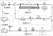
图1为本发明光纤光栅实时光谱分析装置的结构原理图,如图1所示,根据本发明的一方面,提出一种光纤光栅实时光谱分析装置,该装置包括光源模块1、传感单元2、色散单元3、记录模块4和待测单元,其中:Fig. 1 is the structural principle diagram of the fiber grating real-time spectrum analysis device of the present invention, as shown in Fig. 1, according to one aspect of the present invention, propose a kind of fiber grating real-time spectrum analysis device, this device comprises
所述光源模块1用于发射脉冲,其进一步包括飞秒激光器5和光衰减器6。所述飞秒激光器5用于发射用于光栅光谱分析的飞秒激光脉冲,所述光衰减器6用于对所述飞秒激光脉冲进行强度衰减,以避免飞秒激光脉冲的高峰值功率导致光纤中的非线性现象。The
所述传感单元2和所述待测单元通过光学开关22连接所述光源模块1;The
所述传感单元2用于使所述发射脉冲信号发生干涉,其采用的传递函数事先设定。所述传感单元2为一个串联干涉仪结构,其依次包括保偏光纤12和起偏器14,其中,所述保偏光纤12用于将入射脉冲光分成两个偏振模式,并分别沿着保偏光纤12的快轴和慢轴传播;所述起偏器14用于将沿着所述保偏光纤12的快轴和慢轴传播的两束光在所述起偏器14上发生干涉;另外,所述传感单元2还包括偏振控制器11和偏振控制器13,所述偏振控制器11用于控制入射偏振光相对保偏光纤12偏振主轴的角度;所述偏振控制器13用于调节出射偏振光相对起偏器14的角度。The
所述待测单元包括多根串联的FBG7、8(下文以五根FBG为例进行说明)、压电陶瓷纳米平移台10及其驱动器9,所述五根串联的FBG7、8中,前4根FBG7为一组,后1根FBG8为一组,所述FBG8不受轴向应力,而其它四根FBG7均装载在纳米平移台上,当其受到轴向应力时,光栅光谱发生变化;所述压电陶瓷纳米平移台10与所述4根FBG7并联,所述压电陶瓷纳米平移台10与其驱动器9相连。The unit to be tested includes a plurality of
所述色散单元3通过光学开关23连接所述传感单元2和所述待测单元,用于对所述传感单元2或所述待测单元发射的脉冲进行展宽;所述色散单元3包括FBG15、两卷色散补偿光纤16和18和掺铒光纤放大器17,其中,起偏器14发出的光首先经过FBG15,该FBG15放置在温度控制环境中,其光谱位置不受温度和应力的影响,因此作为整个系统的光谱参考点。为了使得FBG15发出的光脉冲的光谱结构在时域上充分展开,因此,在接收光路中,采用两卷色散补偿光纤16和18的串联结构来对FBG15发出的光脉冲进行时域展开处理,另外,为了提高信噪比,在所述两卷色散补偿光纤中间使用掺铒光纤放大器17来增强光信号的强度。The
所述色散单元3中用于对发射脉冲进行展宽的三阶色散和低阶色散对应的传递函数记为H1(ω)和H2(ω),分别由式(1)和式(2)定义:The transfer functions corresponding to the third-order dispersion and the low-order dispersion used to broaden the emission pulse in the
其中,H1(ω)为三阶色散对应的传递函数,H2(ω)为低阶色散对应的传递函数,H0为光纤透过率常数,βn为n阶色散常数,L为色散光纤的长度,β3为3阶色散常数。所述记录模块4连接所述色散单元3,用于记录频域和时域的出射信号。所述记录模块4包括光谱仪21、光电探测器19和示波器20,其中,所述光谱仪21用于探测出射信号的频域光谱;所述光电探测器19用于接收出射时域信号并将其输入到示波器20上进行显示。Among them, H1 (ω) is the transfer function corresponding to the third-order dispersion, H2 (ω) is the transfer function corresponding to the low-order dispersion, H0 is the optical fiber transmittance constant, βn is the n-order dispersion constant, and L is the dispersion The length of the fiber, β3 is the third-order dispersion constant. The
在对待测单元中的五根FBG的光谱进行检测之前,先将所述光学开关22、23连接到所述传感单元2上,根据所述记录模块4记录的频域和时域的出射脉冲信号,将所述频域和时域脉冲信号对应的干涉条纹的峰值坐标采用4阶多项式拟合,即可得到“频率-时间”映射校准关系(即“频率-时间映射”函数),如图2所示,也就是说,根据所述“频率-时间映射”函数,就能实现频域干涉条纹和时域干涉条纹的相互转化。所述时域和频域干涉条纹的对应关系可以用来对整个系统进行“频-时”映射校准。具体地:Before detecting the spectra of the five FBGs in the unit to be measured, the
当所述光学开关22、23连接到所述传感单元2时,分别测得频域和时域的出射脉冲信号(干涉条纹),找出两个出射脉冲信号中的对应峰值位置,并使用4阶多项式拟合,得到频率-时间映射关系:When the
λ=1557.985-1.046t-7.728×10⁻⁴t2-1.738×10⁻⁵t3 (3)λ=1557.985-1.046t-7.728×10⁻⁴ t2 -1.738×10⁻⁵ t3 (3)
其中,波长λ和时间t的单位分别为纳米和纳秒。Wherein, the units of the wavelength λ and the time t are nanometers and nanoseconds, respectively.
然后,在对待测元件中的五根FBG进行超快光谱分析时,再将所述光学开关22、23连接到所述待测单元上。为了达到快速测量的目的,只测量记录模块4输出的时域脉冲信号波形,然后通过式(3)得到的频率-时间映射关系,将所述时域脉冲信号波形转化得到与之对应的频谱波形,即可实现对于待测FBG的超高速光谱检测。Then, the
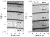
在本发明的一个实施例中,选用的飞秒激光器的型号为IMRAFemtolite 780Model B-4-FC-PD,压电陶瓷纳米平移台10的型号为PIModel P-752.1CD,其驱动器9型号为PI Model E-665.CR,串联的色散补偿光纤的总色散为-952.4ps/nm,并设定FBG15的时域频域位置为坐标转换原点[0ns,1557.985nm]。所述四根FBG7写在13.96cm长度的单模光纤上,所述压电陶瓷纳米平移台10的精度为0.2nm,因此,所加轴向应力的精度为1.43nε;所述压电陶瓷纳米平移台移动17步,每次移动距离为2μm;上述五根FBG:FBG0到FBG5的波长中心和峰值反射率分别为:(1550.173nm,0.9072),(1551.129nm,0.6259),(1552.061nm,0.7169),(1553.035nm,0.6658),(1554.023nm,0.6865)和(1557.985nm,0.9776)。使用光谱仪21和示波器20测得的光谱信号和时域波形如图3所示,图3中(a)为频域透射谱随应力的变化示意图,(b)为时域透射谱随应力的变化示意图。In one embodiment of the present invention, the model of the femtosecond laser selected is IMRAFemtolite 780Model B-4-FC-PD, the model of piezoelectric ceramic nano-
因为色散补偿光纤的群速度色散为负,所以图3中,时域波形是频域波形的水平翻转像。从图4飞秒脉冲经过FBG组的频域透射光强度等高线图(图4(a)为时域透射谱,(b)为频域透射谱)中可以看出:在轴向应力作用下,FBG的中心波长线性移动;然而在时域,FBG的移动轨迹偏离直线,这是由于高阶色散的影响。Because the group velocity dispersion of the dispersion compensating fiber is negative, in Figure 3, the time domain waveform is a horizontally flipped image of the frequency domain waveform. It can be seen from the frequency-domain transmission light intensity contour diagram of the femtosecond pulse passing through the FBG group in Figure 4 (Figure 4(a) is the time-domain transmission spectrum, (b) is the frequency-domain transmission spectrum), it can be seen that: under the action of axial stress Under , the central wavelength of the FBG moves linearly; however, in the time domain, the trajectory of the FBG deviates from a straight line due to the influence of higher-order dispersion.
本发明中,使用式(3)可以将时域波形转化为频域信息,如图5所示,对图中的每一个FBG频谱波形,进行基于Levenberg-Marquardt算法的最小二乘法高斯函数非线性拟合,就可以得到每一个FBG的中心波长。In the present invention, the time domain waveform can be converted into frequency domain information using formula (3), as shown in Figure 5, for each FBG spectrum waveform in the figure, the least square method Gaussian function nonlinearity based on the Levenberg-Marquardt algorithm is carried out Fitting, the center wavelength of each FBG can be obtained.
本发明所使用的高斯拟合函数为:The Gaussian fitting function used in the present invention is:
其中,Bc为强度偏置量,A是高斯曲线包含的面积,W是FBG的宽度,λc是FBG的中心波长。Among them, Bc is the intensity bias, A is the area covered by the Gaussian curve, W is the width of the FBG, and λc is the center wavelength of the FBG.
根据本发明的一个实施例,所述示波器20使用实时采样数字磷光示波器(Tektronix Model TDS7704B,7GHz bandwidth,20Gs/s),在该示波器中,一帧可以采集194个时域光谱。According to an embodiment of the present invention, the
根据本发明的另一方面,还提出一种光纤光栅实时光谱分析方法,如图6所示,该方法包括以下步骤:According to another aspect of the present invention, also propose a kind of fiber grating real-time spectral analysis method, as shown in Figure 6, this method comprises the following steps:
步骤S1,发射用于光栅光谱分析的飞秒激光脉冲;Step S1, emitting femtosecond laser pulses for grating spectral analysis;
所述步骤S 1进一步包括对所述飞秒激光脉冲进行强度衰减的步骤,以避免飞秒激光脉冲的高峰值功率导致光纤中的非线性现象。The step S1 further includes the step of attenuating the intensity of the femtosecond laser pulse, so as to avoid the high peak power of the femtosecond laser pulse from causing nonlinear phenomena in the optical fiber.
步骤S2,使所述发射脉冲信号发生干涉;Step S2, interfering with the transmitted pulse signal;
该步骤中,使用串联干涉仪使所述发射脉冲信号发生干涉。In this step, a series interferometer is used to interfere with the transmitted pulse signal.
步骤S3,对发生干涉之后得到的脉冲进行展宽;Step S3, stretching the pulse obtained after the interference;
该步骤中,对脉冲信号进行展宽的三阶色散和低阶色散对应的传递函数记为H1(ω)和H2(ω),由下式定义:In this step, the transfer functions corresponding to the third-order dispersion and lower-order dispersion for broadening the pulse signal are denoted as H1 (ω) and H2 (ω), which are defined by the following formula:
其中,H1(ω)为三阶色散对应的传递函数,H2(ω)为低阶色散对应的传递函数,H0为光纤透过率常数,βn为n阶色散常数,L为色散光纤的长度,β3为3阶色散常数。Among them, H1 (ω) is the transfer function corresponding to the third-order dispersion, H2 (ω) is the transfer function corresponding to the low-order dispersion, H0 is the optical fiber transmittance constant, βn is the n-order dispersion constant, and L is the dispersion The length of the fiber, β3 is the third-order dispersion constant.
步骤S4,记录并显示频域和时域的出射脉冲信号;Step S4, recording and displaying outgoing pulse signals in frequency domain and time domain;
步骤S5,根据频域和时域的出射脉冲信号,得到“频率-时间”映射校准关系;Step S5, according to the outgoing pulse signal in the frequency domain and the time domain, obtain the "frequency-time" mapping calibration relationship;
所述步骤S5进一步包括以下步骤:Said step S5 further comprises the following steps:
步骤S51,分别测得频域和时域的出射脉冲信号;Step S51, respectively measuring outgoing pulse signals in frequency domain and time domain;
步骤S52,找出两个出射脉冲信号中的对应峰值位置,并使用4阶多项式拟合,得到“频率-时间”映射校准关系:Step S52, find out the corresponding peak positions in the two outgoing pulse signals, and use the fourth-order polynomial fitting to obtain the "frequency-time" mapping calibration relationship:
λ=1557.985-1.046t-7.728×10⁻⁴t2-1.738×10⁻⁵t3,λ=1557.985-1.046t-7.728×10⁻⁴ t2 -1.738×10⁻⁵ t3 ,
其中,波长λ和时间t的单位分别为纳米和纳秒。Wherein, the units of the wavelength λ and the time t are nanometers and nanoseconds, respectively.
步骤S6,将待测的多个FBG串联起来,将除最后一个FBG的所有FBG与压电陶瓷纳米平移台并联;Step S6, connecting multiple FBGs to be tested in series, and connecting all FBGs except the last FBG to the piezoelectric ceramic nano-translation stage in parallel;
步骤S7,发射用于光栅光谱分析的飞秒激光脉冲;Step S7, emitting femtosecond laser pulses for grating spectral analysis;
所述步骤S7进一步包括对所述飞秒激光脉冲进行强度衰减的步骤,以避免飞秒激光脉冲的高峰值功率导致光纤中的非线性现象。The step S7 further includes a step of attenuating the intensity of the femtosecond laser pulse, so as to avoid the high peak power of the femtosecond laser pulse from causing nonlinear phenomena in the optical fiber.
步骤S8,对经过待测FBG的脉冲信号进行展宽;Step S8, stretching the pulse signal passing through the FBG to be tested;
该步骤中,使用所述三阶色散和低阶色散对应的传递函数对信号进行展宽。In this step, the signal is broadened by using the transfer function corresponding to the third-order dispersion and the lower-order dispersion.
步骤S9,记录时域脉冲信号波形,通过所述“频率-时间”映射校准关系,将所述时域脉冲信号波形转化得到与之对应的频谱波形,完成对于待测FBG的超高速光谱检测。Step S9, record the time-domain pulse signal waveform, convert the time-domain pulse signal waveform to obtain the corresponding spectrum waveform through the "frequency-time" mapping calibration relationship, and complete the ultra-high-speed spectral detection of the FBG to be tested.
所述步骤S9中,将时域脉冲信号波形转化得到与之对应的频谱波形,完成对于待测FBG的超高速光谱检测进一步包括:对每一个FBG的频谱波形进行基于Levenberg-Marquardt算法的最小二乘法高斯函数非线性拟合,得到每一个FBG的中心波长,其中,用于拟合的高斯函数为:In the step S9, the time-domain pulse signal waveform is converted to obtain the corresponding spectral waveform, and the ultra-high-speed spectral detection for the FBG to be tested further includes: performing the least squares based on the Levenberg-Marquardt algorithm on the spectral waveform of each FBG The multiplicative Gaussian function is nonlinearly fitted to obtain the center wavelength of each FBG, where the Gaussian function used for fitting is:
其中,Bc为强度偏置量,A是高斯曲线包含的面积,W是FBG的宽度,λc是FBG的中心波长。Among them, Bc is the intensity bias, A is the area covered by the Gaussian curve, W is the width of the FBG, and λc is the center wavelength of the FBG.
综上,采用本发明的技术方案,能够获得:In summary, adopting the technical solution of the present invention can obtain:
一、超快的光谱分析速度:1. Ultra-fast spectral analysis speed:
“频率-时间映射”函数可以将时域信号转化为频域信号,由于示波器对时域信号的采集相比较直接使用光谱仪测量谱线要快,因此采用本发明的方法可以实现光谱的快速分析。The "frequency-time mapping" function can convert time-domain signals into frequency-domain signals. Since the collection of time-domain signals by an oscilloscope is faster than directly using a spectrometer to measure spectral lines, the method of the present invention can realize rapid analysis of spectra.
二、大的测量动态范围:2. Large measurement dynamic range:
由于使用飞秒激光脉冲作为光源,飞秒脉冲的宽光谱为FBG光谱测量提供了大的动态范围。Due to the use of femtosecond laser pulses as light sources, the wide spectrum of femtosecond pulses provides a large dynamic range for FBG spectroscopy measurements.
以上所述的具体实施例,对本发明的目的、技术方案和有益效果进行了进一步详细说明,所应理解的是,以上所述仅为本发明的具体实施例而已,并不用于限制本发明,凡在本发明的精神和原则之内,所做的任何修改、等同替换、改进等,均应包含在本发明的保护范围之内。The specific embodiments described above have further described the purpose, technical solutions and beneficial effects of the present invention in detail. It should be understood that the above descriptions are only specific embodiments of the present invention and are not intended to limit the present invention. Any modifications, equivalent replacements, improvements, etc. made within the spirit and principles of the present invention shall be included within the protection scope of the present invention.
Claims (21)
Priority Applications (1)
| Application Number | Priority Date | Filing Date | Title |
|---|---|---|---|
| CN201210315466.1ACN102853913B (en) | 2012-08-30 | 2012-08-30 | Real-time spectrum analysis device and method of fiber bragg grating |
Applications Claiming Priority (1)
| Application Number | Priority Date | Filing Date | Title |
|---|---|---|---|
| CN201210315466.1ACN102853913B (en) | 2012-08-30 | 2012-08-30 | Real-time spectrum analysis device and method of fiber bragg grating |
Publications (2)
| Publication Number | Publication Date |
|---|---|
| CN102853913Atrue CN102853913A (en) | 2013-01-02 |
| CN102853913B CN102853913B (en) | 2014-07-16 |
Family
ID=47400701
Family Applications (1)
| Application Number | Title | Priority Date | Filing Date |
|---|---|---|---|
| CN201210315466.1AExpired - Fee RelatedCN102853913B (en) | 2012-08-30 | 2012-08-30 | Real-time spectrum analysis device and method of fiber bragg grating |
Country Status (1)
| Country | Link |
|---|---|
| CN (1) | CN102853913B (en) |
Cited By (3)
| Publication number | Priority date | Publication date | Assignee | Title |
|---|---|---|---|---|
| CN104377533A (en)* | 2014-11-10 | 2015-02-25 | 中国电子科技集团公司第四十四研究所 | Phase shift optical grating based frequency self-stabilization photoelectric oscillator |
| CN108762700A (en)* | 2018-06-07 | 2018-11-06 | 华南理工大学 | A kind of spectrum characterization bearing calibration of output equipment and device |
| CN115950839A (en)* | 2023-02-24 | 2023-04-11 | 南京信息工程大学 | A Super-resolution Spectral Analysis Method Based on Spectral Mapping |
Citations (4)
| Publication number | Priority date | Publication date | Assignee | Title |
|---|---|---|---|---|
| GB2281618A (en)* | 1993-09-01 | 1995-03-08 | Furukawa Research & Engineerin | Method and apparatus for measuring a characteristic of an optical fibre |
| US6137565A (en)* | 1998-05-15 | 2000-10-24 | Jenoptik Aktiengesellschaft | Bragg grating temperature/strain fiber sensor having combination interferometer/spectrometer output arrangement |
| WO2004012365A1 (en)* | 2002-07-26 | 2004-02-05 | Teraxion Inc. | Tunable chromatic dispersion compensator |
| CN102636272A (en)* | 2012-03-22 | 2012-08-15 | 中国科学院上海光学精密机械研究所 | Femtosecond laser pulse measurement method based on transient grating effect and device |
- 2012
- 2012-08-30CNCN201210315466.1Apatent/CN102853913B/ennot_activeExpired - Fee Related
Patent Citations (4)
| Publication number | Priority date | Publication date | Assignee | Title |
|---|---|---|---|---|
| GB2281618A (en)* | 1993-09-01 | 1995-03-08 | Furukawa Research & Engineerin | Method and apparatus for measuring a characteristic of an optical fibre |
| US6137565A (en)* | 1998-05-15 | 2000-10-24 | Jenoptik Aktiengesellschaft | Bragg grating temperature/strain fiber sensor having combination interferometer/spectrometer output arrangement |
| WO2004012365A1 (en)* | 2002-07-26 | 2004-02-05 | Teraxion Inc. | Tunable chromatic dispersion compensator |
| CN102636272A (en)* | 2012-03-22 | 2012-08-15 | 中国科学院上海光学精密机械研究所 | Femtosecond laser pulse measurement method based on transient grating effect and device |
Non-Patent Citations (1)
| Title |
|---|
| 朱莉莉,陈胜钰,邱怡申: "《光纤色散的频谱分析》", 《福建师范大学学报》* |
Cited By (5)
| Publication number | Priority date | Publication date | Assignee | Title |
|---|---|---|---|---|
| CN104377533A (en)* | 2014-11-10 | 2015-02-25 | 中国电子科技集团公司第四十四研究所 | Phase shift optical grating based frequency self-stabilization photoelectric oscillator |
| CN104377533B (en)* | 2014-11-10 | 2017-03-22 | 中国电子科技集团公司第四十四研究所 | Phase shift optical grating based frequency self-stabilization photoelectric oscillator |
| CN108762700A (en)* | 2018-06-07 | 2018-11-06 | 华南理工大学 | A kind of spectrum characterization bearing calibration of output equipment and device |
| CN108762700B (en)* | 2018-06-07 | 2020-12-08 | 华南理工大学 | Spectral characterization correction method and device for output device |
| CN115950839A (en)* | 2023-02-24 | 2023-04-11 | 南京信息工程大学 | A Super-resolution Spectral Analysis Method Based on Spectral Mapping |
Also Published As
| Publication number | Publication date |
|---|---|
| CN102853913B (en) | 2014-07-16 |
Similar Documents
| Publication | Publication Date | Title |
|---|---|---|
| EP1705471B1 (en) | Apparatus for measuring differential mode delay of multimode optical fiber | |
| JP2020115125A (en) | Broadband pulse light source unit, method for associating time and wavelength in broadband pulsed light, and spectroscopic measurement device | |
| CN106895790A (en) | Distributing optical fiber sensing resolution method is lifted in a kind of probe beam deflation | |
| CN105783999B (en) | Reference optical fiber eliminates temperature strain cross sensitivity method in a kind of probe beam deflation | |
| CN110749873B (en) | A femtosecond laser radar and gas component detection method | |
| CN105466349B (en) | In a kind of probe beam deflation strain measurement sensitivity method is improved with thin cladded-fiber | |
| CN105865754B (en) | A kind of measurement apparatus of fibre optic interferometer arm length difference | |
| CN105953919B (en) | A kind of all -fiber Fourier spectrum analyzer | |
| CN108562237B (en) | A device and method for spectral calibration in an optical frequency domain reflectometry sensing system using an HCN gas cell | |
| CN115452015B (en) | Phase noise accurate correction optical frequency domain reflectometer for double-scale reference interference | |
| CN102853913B (en) | Real-time spectrum analysis device and method of fiber bragg grating | |
| CN212007737U (en) | All-fiber type dispersion measuring device based on spectral interference | |
| CN104038281B (en) | The long range high-resolution probe beam deflation demodulation method that nonlinear phase is estimated | |
| CN113804412A (en) | Optical fiber device micro-chromaticity dispersion measuring device based on ring light path structure | |
| US10816720B2 (en) | Optical fiber with specialized figure-of-merit and applications therefor | |
| CN108507981A (en) | Silica-based waveguides back reflection sensing device based on OFDR and its measurement method | |
| CN110401482A (en) | A device and method for measuring optical fiber dispersion using wavelength-time mapping | |
| Du et al. | Fast and wideband optical fiber dispersion measurement using the pulse delay method based on super-continuum laser | |
| CN115711633A (en) | Phase noise accurate correction optical frequency domain reflectometer of loop structure reference interferometer | |
| CN102937481B (en) | Femtosecond laser pulse complete reconstruction system and method | |
| CN109633196B (en) | All-fiber chirped pulse velocity interferometer | |
| CN113804405A (en) | Micro optical fiber dispersion measuring device based on double-coupler ring optical path structure | |
| Grigor’ev et al. | Methods for calibrating high-resolution optical reflectometers operating in the frequency domain | |
| RU2797693C1 (en) | Method for measuring parameters of refractive index inhomogeneities along the length of an optical fibre and an optical frequency domain reflectometer | |
| CN113804413B (en) | All-fiber laser tuning frequency measuring method and measuring device |
Legal Events
| Date | Code | Title | Description |
|---|---|---|---|
| C06 | Publication | ||
| PB01 | Publication | ||
| C10 | Entry into substantive examination | ||
| SE01 | Entry into force of request for substantive examination | ||
| C14 | Grant of patent or utility model | ||
| GR01 | Patent grant | ||
| CF01 | Termination of patent right due to non-payment of annual fee | Granted publication date:20140716 Termination date:20210830 | |
| CF01 | Termination of patent right due to non-payment of annual fee |