CN102846368B - An electrocoagulation tweezers system that can automatically adjust the temperature of the tip of the tweezers and has a support - Google Patents
An electrocoagulation tweezers system that can automatically adjust the temperature of the tip of the tweezers and has a supportDownload PDFInfo
- Publication number
- CN102846368B CN102846368BCN201210316009.4ACN201210316009ACN102846368BCN 102846368 BCN102846368 BCN 102846368BCN 201210316009 ACN201210316009 ACN 201210316009ACN 102846368 BCN102846368 BCN 102846368B
- Authority
- CN
- China
- Prior art keywords
- forceps
- temperature
- bar
- base
- tweezers
- Prior art date
- Legal status (The legal status is an assumption and is not a legal conclusion. Google has not performed a legal analysis and makes no representation as to the accuracy of the status listed.)
- Expired - Fee Related
Links
Images


Landscapes
- Cleaning In General (AREA)
Abstract
Description
Translated fromChinese技术领域technical field
本发明涉及一种电凝镊系统。The invention relates to an electrocoagulation tweezers system.
背景技术Background technique
现有的电凝镊依次包括镊尖、绝缘镊杆和电极座,电极座后部的插头通过导线与外部的主机相连电凝镊的镊尖向病灶组织提供高频电能,使镊尖两端之间的蛋白质脱水而凝固,达到止血的目的。由于它的作用范围只限于两个镊尖之间,因此对相邻组织的损伤程度和影响范围很小,相当安全。Existing electrocoagulation forceps include tweezers tip, insulated tweezers rod and electrode base in turn, the plug at the rear of the electrode base is connected to the external host through wires. The protein in between is dehydrated and coagulated to achieve the purpose of hemostasis. Because its range of action is limited to between the two tweezers, the degree of damage and range of influence on adjacent tissues is very small, and it is quite safe.
在电凝镊进行使用完毕后,通常是直接放在托盘内。再次使用之前,必须要对两个镊尖部分进行清洁消毒。通常的做法是人工使用将浸过酒精或蒸馏水的棉球、医用纱布对镊尖进行擦拭,或者使用射线消毒、高温蒸汽消毒、或消毒液浸泡消毒等方法,但是此种方法需要人工来专门来做,浪费时间,效率较低。After the electrocoagulation tweezers are used, they are usually placed directly in the tray. Both tweezers tip parts must be cleaned and disinfected before reuse. The usual method is to manually wipe the tip of the tweezers with cotton balls or medical gauze soaked in alcohol or distilled water, or to use radiation disinfection, high-temperature steam disinfection, or soaking disinfection in disinfectant, etc. Doing it, wastes time and is less efficient.
发明内容Contents of the invention
本发明的目的是提供一种可以自动调整镊尖温度和具有支座的电凝镊系统。The purpose of the present invention is to provide an electrocoagulation tweezers system which can automatically adjust the temperature of tweezers tip and has a support.
为了实现上述目的,采用以下技术方案,一种可以自动调整镊尖温度和具有支座的电凝镊系统,其特征在于:系统包括电凝镊镊体、为镊体提供电源的主机和支座,其中镊体包括镊杆和镊尖,所述镊尖上设置有温度检测装置,温度检测装置将检测到的温度反馈至主机内的芯片,芯片将此温度与预订温度经过比较后调整镊尖输出的功率,对镊尖温度进行调整;In order to achieve the above purpose, the following technical scheme is adopted, an electrocoagulation tweezers system that can automatically adjust the temperature of the tweezers tip and has a support, is characterized in that: the system includes an electrocoagulation tweezers body, a host and a support that provide power for the tweezers body , wherein the tweezers body includes a tweezers rod and a tweezers tip, the tweezers tip is provided with a temperature detection device, and the temperature detection device feeds back the detected temperature to the chip in the host, and the chip adjusts the tweezers tip after comparing the temperature with the preset temperature Output power, adjust the temperature of the tweezers tip;
支座包括底座,底座上具有与电凝镊两个镊杆相配合的凹槽,凹槽的下部具有容纳镊尖的空腔,底座上还具有主控芯片和位置感应器,两个凹槽的中间设置有阻挡架,阻挡架为中空结构,具有容纳腔,阻挡架下部伸入底座内,在阻挡架的外侧面从上至下依次排列有若干位置感应器,底座内还设置有清洁装置,其中清洁装置的整体上呈倒立的T型结构,清洁装置包括水平杆和竖直杆,其中竖直杆的上端位于阻挡架的内部,竖直杆的杆身上具有向外的第一凸起,第一凸起和阻挡架的下端内壁之间具有第一弹簧,竖直杆的上部空间设置有被第一电机旋转轴带动的第一椭圆旋转杆,竖直杆的下部连接有水平容纳杆,在水平容纳杆内设置有两个对称设置的水平杆,两个水平杆的中间设置有由第二电机旋转轴带动的第二椭圆旋转杆,水平杆的杆身上具有第二凸起,在第二凸起和水平容纳杆端部内壁之间设置有第二弹簧,水平杆的远端伸出水平容纳杆,其端部铰接有具有柔性物质层的清洁擦。The support includes a base, and the base has a groove that matches the two tweezers rods of the electrocoagulation tweezers. The lower part of the groove has a cavity for accommodating the tip of the tweezers. The base also has a main control chip and a position sensor, and two grooves There is a blocking frame in the middle of the frame, the blocking frame is a hollow structure, has a receiving cavity, the lower part of the blocking frame extends into the base, and a number of position sensors are arranged in sequence from top to bottom on the outer surface of the blocking frame, and a cleaning device is also installed in the base , wherein the whole of the cleaning device is an inverted T-shaped structure, the cleaning device includes a horizontal bar and a vertical bar, wherein the upper end of the vertical bar is located inside the blocking frame, and the shaft of the vertical bar has an outward first protrusion , there is a first spring between the first protrusion and the inner wall of the lower end of the blocking frame, the upper space of the vertical rod is provided with a first elliptical rotating rod driven by the rotating shaft of the first motor, and the lower part of the vertical rod is connected with a horizontal accommodating rod , two symmetrically arranged horizontal rods are arranged in the horizontal accommodation rod, and a second elliptical rotating rod driven by the second motor rotation shaft is arranged in the middle of the two horizontal rods. The shaft body of the horizontal rod has a second protrusion. A second spring is arranged between the second protrusion and the inner wall at the end of the horizontal rod. The far end of the horizontal rod protrudes from the horizontal rod, and a cleaning wipe with a flexible material layer is hinged at the end.
所述底座上凹槽的入口处设置有束紧装置,束紧装置包括弹性钢丝,弹性钢丝的一端连接有固定在底座内的第三弹簧,弹性钢丝的另一端连接于第三电机的旋转轴。The entrance of the groove on the base is provided with a tightening device, the tightening device includes an elastic steel wire, one end of the elastic steel wire is connected to a third spring fixed in the base, and the other end of the elastic steel wire is connected to the rotating shaft of the third motor .
所述束紧装置的竖直面上设置有擦拭装置,其中擦拭装置包括上下设置的第四电机旋转轴和第五电机旋转轴,第四电机旋转轴和第五电机旋转轴上分别缠绕有擦拭布,且擦拭布位于束紧装置围成的圈的内侧。A wiping device is provided on the vertical surface of the tightening device, wherein the wiping device includes a fourth motor rotation shaft and a fifth motor rotation shaft arranged up and down, and a wiping device is wound on the fourth motor rotation shaft and the fifth motor rotation shaft respectively. cloth, and the wiper is located inside the circle formed by the tightening device.
本发明结构简单,电凝镊在使用完毕后,可以直接插入到支座上的凹槽内,位置感应器感应到有镊杆插入,将信号传递给主控芯片,主控芯片就会控制擦拭清洁装置自动完成电凝镊的擦拭清洁工作。通过实时对镊尖的温度进行检测,将镊尖的温度控制在一定的范围之内,保证了电凝镊的粘合效果,避免了过热现象的发生。本发明原理简单,成本低,体积小,效率高,具有很好的实用价值。The invention has a simple structure. After the electrocoagulation tweezers are used, they can be directly inserted into the groove on the support. The position sensor senses the insertion of the tweezers rod, and transmits the signal to the main control chip, and the main control chip will control the wiping. The cleaning device automatically completes the wiping and cleaning work of the electrocoagulation forceps. By detecting the temperature of the tip of the tweezers in real time, the temperature of the tip of the tweezers is controlled within a certain range, which ensures the bonding effect of the electrocoagulation tweezers and avoids the occurrence of overheating. The invention has simple principle, low cost, small volume, high efficiency and good practical value.
附图说明Description of drawings
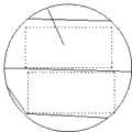
图1为本发明实施例中支座的结构示意图;Fig. 1 is the structural representation of support in the embodiment of the present invention;
图2为图1中清洁装置的结构示意图;Fig. 2 is the structural representation of cleaning device in Fig. 1;
图3为图1的俯视图;Fig. 3 is the top view of Fig. 1;
图4为本发明实施例中支座上的束紧装置的结构示意图;Fig. 4 is a schematic structural view of the tightening device on the support in the embodiment of the present invention;
图5为本发明实施例中支座上的束紧装置和擦拭装置的结构示意图;5 is a schematic structural view of the tightening device and the wiping device on the support in the embodiment of the present invention;
图6为本发明实施例中镊体和主机的结构示意图;Fig. 6 is a schematic structural view of the tweezers and the host in an embodiment of the present invention;
图7为图6中A的放大图。FIG. 7 is an enlarged view of A in FIG. 6 .
具体实施方式Detailed ways
下面结合附图和具体实施例对本发明做进一步的说明。Below in conjunction with accompanying drawing and specific embodiment the present invention will be further described.
如图1、图2和图3所示,支座包括底座1-5,底座1-5上具有与电凝镊两个镊杆2-2相配合的凹槽1-2,凹槽1-2的下部具有容纳镊尖的空腔1-1,底座上还具有主控芯片和位置感应器1-3,两个凹槽1-2的中间设置有阻挡架1-4,阻挡架1-4为中空结构,具有容纳腔1-17,其下部伸入底座内,在阻挡架的外侧面从上至下依次排列有若干位置感应器1-3,底座1-5内还设置有清洁装置,其中清洁装置的整体上呈倒立的T型结构,由水平杆1-8和竖直杆1-13组成,其中竖直杆的上端位于阻挡架的内部,竖直杆1-13的杆身上具有向外的第一凸起,第一凸起和阻挡架的底部内壁之间具有第一弹簧1-14,竖直杆的上部空间设置有被第一电机旋转轴1-16带动的第一椭圆旋转杆1-15,竖直杆1-13的下部连接有水平容纳杆1-12,在水平容纳杆内设置有对称设置的水平杆1-8,两个水平杆1-8的中间设置有由第二电机旋转轴1-6带动的第二椭圆旋转杆1-7,水平杆的杆身上具有第二凸起,在第二凸起和水平容纳杆之间设置有第二弹簧1-9,水平杆的远端伸出水平容纳杆,其端部铰接有具有柔性物质层1-10的清洁擦1-11。As shown in Figure 1, Figure 2 and Figure 3, the support includes a base 1-5, and the base 1-5 has a groove 1-2 that matches the two tweezers bars 2-2 of the electrocoagulation tweezers, and the groove 1- The lower part of the 2 has a cavity 1-1 for accommodating the tip of the tweezers. The base also has a main control chip and a position sensor 1-3. A blocking frame 1-4 is arranged in the middle of the two grooves 1-2. The blocking frame 1- 4 is a hollow structure with an accommodating cavity 1-17, the lower part of which extends into the base, and a number of position sensors 1-3 are arranged in sequence from top to bottom on the outer surface of the blocking frame, and a cleaning device is also arranged in the base 1-5 , wherein the cleaning device is an inverted T-shaped structure as a whole, consisting of a horizontal bar 1-8 and a vertical bar 1-13, wherein the upper end of the vertical bar is located inside the blocking frame, and the shaft of the vertical bar 1-13 There is an outward first protrusion, a first spring 1-14 is provided between the first protrusion and the bottom inner wall of the blocking frame, and the upper space of the vertical rod is provided with a first spring driven by the first motor rotation shaft 1-16. The elliptical rotating rod 1-15, the bottom of the vertical rod 1-13 is connected with a horizontal receiving rod 1-12, and a symmetrically arranged horizontal rod 1-8 is arranged in the horizontal receiving rod, and the middle of the two horizontal rods 1-8 is arranged There is a second elliptical rotating rod 1-7 driven by the second motor rotating shaft 1-6, the shaft of the horizontal rod has a second protrusion, and a second spring 1-7 is arranged between the second protrusion and the horizontal accommodation rod. 9. The far end of the horizontal rod protrudes from the horizontal receiving rod, and the end is hinged with a cleaning wipe 1-11 having a flexible material layer 1-10.
如图4所示,底座上凹槽1-2的入口处设置有束紧装置,束紧装置包括弹性钢丝1-18,弹性钢丝的一端连接有第三弹簧1-19,第三弹簧固定在底座内,弹性钢丝的另一端连接于第三电机的旋转轴1-20。As shown in Figure 4, the entrance of groove 1-2 on the base is provided with tightening device, and tightening device comprises elastic steel wire 1-18, and one end of elastic steel wire is connected with the 3rd spring 1-19, and the 3rd spring is fixed on In the base, the other end of the elastic steel wire is connected to the rotating shaft 1-20 of the third motor.
如图5所示,在束紧装置的竖直面上设置有擦拭装置,其中擦拭装置包括上下设置的第四电机旋转轴1-21和第五电机旋转轴1-22,第四电机旋转轴1-21和第五电机旋转轴1-22上分别缠绕有擦拭布1-23,且擦拭布1-23位于束紧装置围成的圈的内侧。As shown in Figure 5, a wiping device is provided on the vertical surface of the tightening device, wherein the wiping device includes a fourth motor rotation shaft 1-21 and a fifth motor rotation shaft 1-22 arranged up and down, the fourth motor rotation shaft 1-21 and the fifth motor rotating shaft 1-22 are respectively wound with a wiping cloth 1-23, and the wiping cloth 1-23 is located inside the circle formed by the tightening device.
使用时,将电凝镊插入支座中,其中镊杆被阻挡架支撑,位置感应器一旦感应到有镊杆插入停止后,即将信号传递给主控芯片,由主控芯片首先控制第三电机转动拉紧支座上的弹性钢丝,使得电凝镊镊杆位置被固定。然后,第二电机旋转半周,使得水平杆向外伸出,抵在镊尖的内侧,然后主控芯片再控制第一电机不断旋转,将第一椭圆旋转杆旋转,使得将竖直杆上下运动,柔性物质层与镊尖部位上下摩擦,进行擦拭清洁的工作。When in use, insert the electrocoagulation tweezers into the support, where the tweezers rod is supported by the blocking frame. Once the position sensor senses that the tweezers rod is inserted and stops, it will transmit the signal to the main control chip, and the main control chip will first control the third motor. Turn and tighten the elastic steel wire on the support so that the position of the electrocoagulation tweezers is fixed. Then, the second motor rotates half a circle, so that the horizontal rod protrudes outwards and touches the inner side of the tweezers, and then the main control chip controls the first motor to rotate continuously, rotating the first elliptical rotating rod, so that the vertical rod moves up and down , the flexible material layer rubs up and down with the tip of the tweezers to perform the work of wiping and cleaning.
由于清洁擦与水平杆之间为铰接,能够保证清洁擦与接触镊尖后会自动调整位置,保证两者贴紧。Since the cleaning wipe and the horizontal bar are hinged, it can be ensured that the position of the cleaning wipe and the tweezers will be automatically adjusted after touching the tip of the tweezers, so that the two are tightly attached.
清洁工作完成后,第三电机反向转动四分之一圈,然后可拔出电凝镊,当位置传感器发现镊杆抽出时,第四电机和第五电机旋转,使擦拭布运动的方向与镊杆运动的方向相反,这样可以对镊尖达到一个更好的清洁效果,也可以实现对电凝镊镊尖部位的干燥功能。After the cleaning work is completed, the third motor reversely rotates a quarter turn, and then the electrocoagulation tweezers can be pulled out. When the position sensor detects that the tweezers rod is pulled out, the fourth motor and the fifth motor rotate, so that the direction of movement of the wiping cloth is the same as that of the tweezers. The direction of movement of the tweezers rod is opposite, so that a better cleaning effect can be achieved on the tweezers tip, and the function of drying the tweezers tip of the electrocoagulation tweezers can also be realized.
当位置感应器感应到镊杆抽走,会再次将信号传递给主控芯片,由主控芯片控制清洁装置上的水平杆回归原位,并控制第三电机反向转动,完全释放束紧装置,从而完成整个支座的清洁消毒和干燥工作。When the position sensor detects that the tweezers are pulled away, the signal will be transmitted to the main control chip again, and the main control chip will control the horizontal rod on the cleaning device to return to its original position, and control the third motor to rotate in reverse to completely release the tightening device , so as to complete the cleaning, disinfection and drying of the entire bearing.
如图6和图7所示,镊体包括镊尖2-1和镊杆2-2,镊杆2-2后部具有电极座2-3,电极座2-3上具有插头2-4,插头2-4通过电缆与主机2-5相连,主机2-5通过电缆为镊杆提供电力。在镊尖2-1的内侧埋有温度传感器2-6,温度传感器2-6将镊尖的实时温度传送回主机的内部芯片,若温度低于40℃,则加大电流,使得镊尖的温度升高;若温度高于90℃,则减少电流,使得镊尖的温度降低。通过这样的控制,镊尖的温度将保持在最佳的工作状态,保证了血管粘合的效果。As shown in Figures 6 and 7, the tweezers body includes a tweezers tip 2-1 and a tweezers rod 2-2, the rear portion of the tweezers rod 2-2 has an electrode seat 2-3, and the electrode seat 2-3 has a plug 2-4, The plug 2-4 is connected with the host 2-5 through the cable, and the host 2-5 provides power for the tweezers bar through the cable. A temperature sensor 2-6 is buried inside the tweezers tip 2-1, and the temperature sensor 2-6 transmits the real-time temperature of the tweezers tip back to the internal chip of the host. If the temperature is lower than 40°C, the current is increased to make the tweezers tip The temperature rises; if the temperature is higher than 90°C, reduce the current to lower the temperature of the tweezers. Through such control, the temperature of the tip of the tweezers will be kept in the best working state, ensuring the effect of blood vessel bonding.
本发明原理简单,成本低,体积小,效率高,具有很好的实用价值。The invention has simple principle, low cost, small volume, high efficiency and good practical value.
Claims (3)
Priority Applications (1)
| Application Number | Priority Date | Filing Date | Title |
|---|---|---|---|
| CN201210316009.4ACN102846368B (en) | 2012-08-31 | 2012-08-31 | An electrocoagulation tweezers system that can automatically adjust the temperature of the tip of the tweezers and has a support |
Applications Claiming Priority (1)
| Application Number | Priority Date | Filing Date | Title |
|---|---|---|---|
| CN201210316009.4ACN102846368B (en) | 2012-08-31 | 2012-08-31 | An electrocoagulation tweezers system that can automatically adjust the temperature of the tip of the tweezers and has a support |
Related Child Applications (3)
| Application Number | Title | Priority Date | Filing Date |
|---|---|---|---|
| CN201410132804.7ADivisionCN103932781A (en) | 2012-08-31 | 2012-08-31 | Electro-coagulation forceps system capable of automatically adjusting forceps point temperature and provided with support |
| CN201410132803.2ADivisionCN103860262A (en) | 2012-08-31 | 2012-08-31 | Electric coagulation forceps system capable of automatically regulating temperatures of forceps tips and provided with support |
| CN201410132805.1ADivisionCN103860263A (en) | 2012-08-31 | 2012-08-31 | Electric coagulation forceps system capable of automatically regulating temperatures of forceps tips and provided with support |
Publications (2)
| Publication Number | Publication Date |
|---|---|
| CN102846368A CN102846368A (en) | 2013-01-02 |
| CN102846368Btrue CN102846368B (en) | 2014-05-14 |
Family
ID=47393633
Family Applications (1)
| Application Number | Title | Priority Date | Filing Date |
|---|---|---|---|
| CN201210316009.4AExpired - Fee RelatedCN102846368B (en) | 2012-08-31 | 2012-08-31 | An electrocoagulation tweezers system that can automatically adjust the temperature of the tip of the tweezers and has a support |
Country Status (1)
| Country | Link |
|---|---|
| CN (1) | CN102846368B (en) |
Families Citing this family (8)
| Publication number | Priority date | Publication date | Assignee | Title |
|---|---|---|---|---|
| CN105615996A (en)* | 2013-02-28 | 2016-06-01 | 重庆润泽医药有限公司 | Convenient and fast electrocoagulation forceps system |
| CN105286981A (en)* | 2014-06-30 | 2016-02-03 | 重庆润泽医药有限公司 | Medical portable electric coagulation forceps system |
| CN105266889A (en)* | 2014-06-30 | 2016-01-27 | 重庆润泽医药有限公司 | Electric coagulation forceps system having cleaning function |
| CN105213020B (en)* | 2014-06-30 | 2018-11-06 | 重庆润泽医药有限公司 | A kind of multi-functional electric coagulation tweezers system |
| CN105310762B (en)* | 2014-06-30 | 2018-11-06 | 重庆润泽医药有限公司 | A kind of small-sized medical hemostasis electric coagulation forcep system |
| CN105615982A (en)* | 2014-10-28 | 2016-06-01 | 重庆润泽医药有限公司 | Smart electric coagulation forceps system |
| CN105615984A (en)* | 2014-10-28 | 2016-06-01 | 重庆润泽医药有限公司 | Intelligent electric coagulation forceps system |
| CN105615988A (en)* | 2014-10-28 | 2016-06-01 | 重庆润泽医药有限公司 | Operating electrocoagulation forceps system |
Citations (5)
| Publication number | Priority date | Publication date | Assignee | Title |
|---|---|---|---|---|
| DE3511107A1 (en)* | 1985-03-27 | 1986-10-02 | Fischer MET GmbH, 7800 Freiburg | DEVICE FOR BIPOLAR HIGH-FREQUENCY COAGULATION OF BIOLOGICAL TISSUE |
| US20030158549A1 (en)* | 2002-02-19 | 2003-08-21 | Swanson David K. | Apparatus for securing an electrophysiology probe to a clamp |
| CN2735941Y (en)* | 2004-08-19 | 2005-10-26 | 李刚 | Gun shape bipolar electric coagulating forceps with sucking and flushing functions |
| US20060195081A1 (en)* | 2005-02-25 | 2006-08-31 | Boston Scientific Scimed, Inc. | Dual mode lesion formation apparatus, systems and methods |
| CN202859287U (en)* | 2012-08-31 | 2013-04-10 | 重庆润泽医药有限公司 | Electric coagulation forceps system capable of automatically adjusting forceps tip temperature and being provided with support |
- 2012
- 2012-08-31CNCN201210316009.4Apatent/CN102846368B/ennot_activeExpired - Fee Related
Patent Citations (5)
| Publication number | Priority date | Publication date | Assignee | Title |
|---|---|---|---|---|
| DE3511107A1 (en)* | 1985-03-27 | 1986-10-02 | Fischer MET GmbH, 7800 Freiburg | DEVICE FOR BIPOLAR HIGH-FREQUENCY COAGULATION OF BIOLOGICAL TISSUE |
| US20030158549A1 (en)* | 2002-02-19 | 2003-08-21 | Swanson David K. | Apparatus for securing an electrophysiology probe to a clamp |
| CN2735941Y (en)* | 2004-08-19 | 2005-10-26 | 李刚 | Gun shape bipolar electric coagulating forceps with sucking and flushing functions |
| US20060195081A1 (en)* | 2005-02-25 | 2006-08-31 | Boston Scientific Scimed, Inc. | Dual mode lesion formation apparatus, systems and methods |
| CN202859287U (en)* | 2012-08-31 | 2013-04-10 | 重庆润泽医药有限公司 | Electric coagulation forceps system capable of automatically adjusting forceps tip temperature and being provided with support |
Also Published As
| Publication number | Publication date |
|---|---|
| CN102846368A (en) | 2013-01-02 |
Similar Documents
| Publication | Publication Date | Title |
|---|---|---|
| CN102846368B (en) | An electrocoagulation tweezers system that can automatically adjust the temperature of the tip of the tweezers and has a support | |
| CN102909184B (en) | Electric coagulation forceps support with wiping and cleaning functions | |
| CN102961182B (en) | Electric coagulation forceps system with illuminating and automatic wiping functions | |
| CN102846372B (en) | Electric coagulation forceps system with supporting seat and function of automatically adjusting temperature of forceps tips | |
| CN102846380B (en) | Electric coagulation forceps support seat with automatic wiping function | |
| CN202823931U (en) | Electric coagulation forceps support with automatic wiping function | |
| CN202951649U (en) | Electric coagulation forceps supporting seat with rotating shafts | |
| CN102846371B (en) | Electric coagulation forceps system with illumination and suction functions and supporting seat | |
| CN203458615U (en) | Disinfecting-wiping support seat for electric coagulation forceps | |
| CN102846373B (en) | Electric coagulation forceps system with extended illumination device and supporting seat | |
| CN102846367B (en) | Electric coagulation forceps system with suction and water dropping functions and supporting seat | |
| CN102908190B (en) | Electric coagulation forceps system with supporting seat capable of automatically cleaning forceps points | |
| CN102846369B (en) | Electric coagulation forceps system with light-guide fiber illumination device and supporting seat | |
| CN202859291U (en) | Electric coagulation tweezers system with automatic tweezers points cleaning function support seat | |
| CN202821606U (en) | Electric coagulation forceps system with illuminating function and support seat | |
| CN202821604U (en) | Electric coagulation forcep system with functions of drawing and dripping and support seat | |
| CN202859287U (en) | Electric coagulation forceps system capable of automatically adjusting forceps tip temperature and being provided with support | |
| CN202859288U (en) | Automatically forcep tips temperature-adjusting electric coagulation forcep system with support | |
| CN103860262A (en) | Electric coagulation forceps system capable of automatically regulating temperatures of forceps tips and provided with support | |
| CN202821599U (en) | Electric coagulation forceps system with light-guide fiber illuminating device and support seat | |
| CN202823929U (en) | Electric coagulation forceps support seat with wiping and cleaning function | |
| CN203578251U (en) | Electric coagulation forceps scrubbing and drying support | |
| CN103932781A (en) | Electro-coagulation forceps system capable of automatically adjusting forceps point temperature and provided with support | |
| CN202821598U (en) | Electric coagulation forceps system with extending illuminating device and support seat | |
| CN202951656U (en) | Electric coagulation forceps support with rotary scrubbing function |
Legal Events
| Date | Code | Title | Description |
|---|---|---|---|
| C06 | Publication | ||
| PB01 | Publication | ||
| C10 | Entry into substantive examination | ||
| SE01 | Entry into force of request for substantive examination | ||
| C14 | Grant of patent or utility model | ||
| GR01 | Patent grant | ||
| CF01 | Termination of patent right due to non-payment of annual fee | ||
| CF01 | Termination of patent right due to non-payment of annual fee | Granted publication date:20140514 Termination date:20190831 |