CN102844220B - Power supply system and vehicle equipped with power supply system - Google Patents
Power supply system and vehicle equipped with power supply systemDownload PDFInfo
- Publication number
- CN102844220B CN102844220BCN201180018479.6ACN201180018479ACN102844220BCN 102844220 BCN102844220 BCN 102844220BCN 201180018479 ACN201180018479 ACN 201180018479ACN 102844220 BCN102844220 BCN 102844220B
- Authority
- CN
- China
- Prior art keywords
- power
- storage device
- charging
- power storage
- converter
- Prior art date
- Legal status (The legal status is an assumption and is not a legal conclusion. Google has not performed a legal analysis and makes no representation as to the accuracy of the status listed.)
- Active
Links
Images


Classifications
- H—ELECTRICITY
- H02—GENERATION; CONVERSION OR DISTRIBUTION OF ELECTRIC POWER
- H02J—CIRCUIT ARRANGEMENTS OR SYSTEMS FOR SUPPLYING OR DISTRIBUTING ELECTRIC POWER; SYSTEMS FOR STORING ELECTRIC ENERGY
- H02J7/00—Circuit arrangements for charging or depolarising batteries or for supplying loads from batteries
- H02J7/02—Circuit arrangements for charging or depolarising batteries or for supplying loads from batteries for charging batteries from AC mains by converters
- B—PERFORMING OPERATIONS; TRANSPORTING
- B60—VEHICLES IN GENERAL
- B60L—PROPULSION OF ELECTRICALLY-PROPELLED VEHICLES; SUPPLYING ELECTRIC POWER FOR AUXILIARY EQUIPMENT OF ELECTRICALLY-PROPELLED VEHICLES; ELECTRODYNAMIC BRAKE SYSTEMS FOR VEHICLES IN GENERAL; MAGNETIC SUSPENSION OR LEVITATION FOR VEHICLES; MONITORING OPERATING VARIABLES OF ELECTRICALLY-PROPELLED VEHICLES; ELECTRIC SAFETY DEVICES FOR ELECTRICALLY-PROPELLED VEHICLES
- B60L50/00—Electric propulsion with power supplied within the vehicle
- B60L50/10—Electric propulsion with power supplied within the vehicle using propulsion power supplied by engine-driven generators, e.g. generators driven by combustion engines
- B60L50/16—Electric propulsion with power supplied within the vehicle using propulsion power supplied by engine-driven generators, e.g. generators driven by combustion engines with provision for separate direct mechanical propulsion
- B—PERFORMING OPERATIONS; TRANSPORTING
- B60—VEHICLES IN GENERAL
- B60L—PROPULSION OF ELECTRICALLY-PROPELLED VEHICLES; SUPPLYING ELECTRIC POWER FOR AUXILIARY EQUIPMENT OF ELECTRICALLY-PROPELLED VEHICLES; ELECTRODYNAMIC BRAKE SYSTEMS FOR VEHICLES IN GENERAL; MAGNETIC SUSPENSION OR LEVITATION FOR VEHICLES; MONITORING OPERATING VARIABLES OF ELECTRICALLY-PROPELLED VEHICLES; ELECTRIC SAFETY DEVICES FOR ELECTRICALLY-PROPELLED VEHICLES
- B60L50/00—Electric propulsion with power supplied within the vehicle
- B60L50/50—Electric propulsion with power supplied within the vehicle using propulsion power supplied by batteries or fuel cells
- B60L50/51—Electric propulsion with power supplied within the vehicle using propulsion power supplied by batteries or fuel cells characterised by AC-motors
- B—PERFORMING OPERATIONS; TRANSPORTING
- B60—VEHICLES IN GENERAL
- B60L—PROPULSION OF ELECTRICALLY-PROPELLED VEHICLES; SUPPLYING ELECTRIC POWER FOR AUXILIARY EQUIPMENT OF ELECTRICALLY-PROPELLED VEHICLES; ELECTRODYNAMIC BRAKE SYSTEMS FOR VEHICLES IN GENERAL; MAGNETIC SUSPENSION OR LEVITATION FOR VEHICLES; MONITORING OPERATING VARIABLES OF ELECTRICALLY-PROPELLED VEHICLES; ELECTRIC SAFETY DEVICES FOR ELECTRICALLY-PROPELLED VEHICLES
- B60L53/00—Methods of charging batteries, specially adapted for electric vehicles; Charging stations or on-board charging equipment therefor; Exchange of energy storage elements in electric vehicles
- B60L53/10—Methods of charging batteries, specially adapted for electric vehicles; Charging stations or on-board charging equipment therefor; Exchange of energy storage elements in electric vehicles characterised by the energy transfer between the charging station and the vehicle
- B60L53/14—Conductive energy transfer
- B—PERFORMING OPERATIONS; TRANSPORTING
- B60—VEHICLES IN GENERAL
- B60L—PROPULSION OF ELECTRICALLY-PROPELLED VEHICLES; SUPPLYING ELECTRIC POWER FOR AUXILIARY EQUIPMENT OF ELECTRICALLY-PROPELLED VEHICLES; ELECTRODYNAMIC BRAKE SYSTEMS FOR VEHICLES IN GENERAL; MAGNETIC SUSPENSION OR LEVITATION FOR VEHICLES; MONITORING OPERATING VARIABLES OF ELECTRICALLY-PROPELLED VEHICLES; ELECTRIC SAFETY DEVICES FOR ELECTRICALLY-PROPELLED VEHICLES
- B60L58/00—Methods or circuit arrangements for monitoring or controlling batteries or fuel cells, specially adapted for electric vehicles
- B60L58/10—Methods or circuit arrangements for monitoring or controlling batteries or fuel cells, specially adapted for electric vehicles for monitoring or controlling batteries
- B60L58/12—Methods or circuit arrangements for monitoring or controlling batteries or fuel cells, specially adapted for electric vehicles for monitoring or controlling batteries responding to state of charge [SoC]
- B—PERFORMING OPERATIONS; TRANSPORTING
- B60—VEHICLES IN GENERAL
- B60L—PROPULSION OF ELECTRICALLY-PROPELLED VEHICLES; SUPPLYING ELECTRIC POWER FOR AUXILIARY EQUIPMENT OF ELECTRICALLY-PROPELLED VEHICLES; ELECTRODYNAMIC BRAKE SYSTEMS FOR VEHICLES IN GENERAL; MAGNETIC SUSPENSION OR LEVITATION FOR VEHICLES; MONITORING OPERATING VARIABLES OF ELECTRICALLY-PROPELLED VEHICLES; ELECTRIC SAFETY DEVICES FOR ELECTRICALLY-PROPELLED VEHICLES
- B60L58/00—Methods or circuit arrangements for monitoring or controlling batteries or fuel cells, specially adapted for electric vehicles
- B60L58/40—Methods or circuit arrangements for monitoring or controlling batteries or fuel cells, specially adapted for electric vehicles for controlling a combination of batteries and fuel cells
- H—ELECTRICITY
- H02—GENERATION; CONVERSION OR DISTRIBUTION OF ELECTRIC POWER
- H02J—CIRCUIT ARRANGEMENTS OR SYSTEMS FOR SUPPLYING OR DISTRIBUTING ELECTRIC POWER; SYSTEMS FOR STORING ELECTRIC ENERGY
- H02J7/00—Circuit arrangements for charging or depolarising batteries or for supplying loads from batteries
- H02J7/007—Regulation of charging or discharging current or voltage
- H02J7/0071—Regulation of charging or discharging current or voltage with a programmable schedule
- H—ELECTRICITY
- H02—GENERATION; CONVERSION OR DISTRIBUTION OF ELECTRIC POWER
- H02J—CIRCUIT ARRANGEMENTS OR SYSTEMS FOR SUPPLYING OR DISTRIBUTING ELECTRIC POWER; SYSTEMS FOR STORING ELECTRIC ENERGY
- H02J7/00—Circuit arrangements for charging or depolarising batteries or for supplying loads from batteries
- H02J7/34—Parallel operation in networks using both storage and other DC sources, e.g. providing buffering
- H02J7/342—The other DC source being a battery actively interacting with the first one, i.e. battery to battery charging
- B—PERFORMING OPERATIONS; TRANSPORTING
- B60—VEHICLES IN GENERAL
- B60L—PROPULSION OF ELECTRICALLY-PROPELLED VEHICLES; SUPPLYING ELECTRIC POWER FOR AUXILIARY EQUIPMENT OF ELECTRICALLY-PROPELLED VEHICLES; ELECTRODYNAMIC BRAKE SYSTEMS FOR VEHICLES IN GENERAL; MAGNETIC SUSPENSION OR LEVITATION FOR VEHICLES; MONITORING OPERATING VARIABLES OF ELECTRICALLY-PROPELLED VEHICLES; ELECTRIC SAFETY DEVICES FOR ELECTRICALLY-PROPELLED VEHICLES
- B60L2210/00—Converter types
- B60L2210/10—DC to DC converters
- B—PERFORMING OPERATIONS; TRANSPORTING
- B60—VEHICLES IN GENERAL
- B60L—PROPULSION OF ELECTRICALLY-PROPELLED VEHICLES; SUPPLYING ELECTRIC POWER FOR AUXILIARY EQUIPMENT OF ELECTRICALLY-PROPELLED VEHICLES; ELECTRODYNAMIC BRAKE SYSTEMS FOR VEHICLES IN GENERAL; MAGNETIC SUSPENSION OR LEVITATION FOR VEHICLES; MONITORING OPERATING VARIABLES OF ELECTRICALLY-PROPELLED VEHICLES; ELECTRIC SAFETY DEVICES FOR ELECTRICALLY-PROPELLED VEHICLES
- B60L2210/00—Converter types
- B60L2210/30—AC to DC converters
- B—PERFORMING OPERATIONS; TRANSPORTING
- B60—VEHICLES IN GENERAL
- B60L—PROPULSION OF ELECTRICALLY-PROPELLED VEHICLES; SUPPLYING ELECTRIC POWER FOR AUXILIARY EQUIPMENT OF ELECTRICALLY-PROPELLED VEHICLES; ELECTRODYNAMIC BRAKE SYSTEMS FOR VEHICLES IN GENERAL; MAGNETIC SUSPENSION OR LEVITATION FOR VEHICLES; MONITORING OPERATING VARIABLES OF ELECTRICALLY-PROPELLED VEHICLES; ELECTRIC SAFETY DEVICES FOR ELECTRICALLY-PROPELLED VEHICLES
- B60L2220/00—Electrical machine types; Structures or applications thereof
- B60L2220/10—Electrical machine types
- B60L2220/14—Synchronous machines
- H—ELECTRICITY
- H02—GENERATION; CONVERSION OR DISTRIBUTION OF ELECTRIC POWER
- H02J—CIRCUIT ARRANGEMENTS OR SYSTEMS FOR SUPPLYING OR DISTRIBUTING ELECTRIC POWER; SYSTEMS FOR STORING ELECTRIC ENERGY
- H02J2207/00—Indexing scheme relating to details of circuit arrangements for charging or depolarising batteries or for supplying loads from batteries
- H02J2207/20—Charging or discharging characterised by the power electronics converter
- H—ELECTRICITY
- H02—GENERATION; CONVERSION OR DISTRIBUTION OF ELECTRIC POWER
- H02J—CIRCUIT ARRANGEMENTS OR SYSTEMS FOR SUPPLYING OR DISTRIBUTING ELECTRIC POWER; SYSTEMS FOR STORING ELECTRIC ENERGY
- H02J2207/00—Indexing scheme relating to details of circuit arrangements for charging or depolarising batteries or for supplying loads from batteries
- H02J2207/40—Indexing scheme relating to details of circuit arrangements for charging or depolarising batteries or for supplying loads from batteries adapted for charging from various sources, e.g. AC, DC or multivoltage
- H—ELECTRICITY
- H02—GENERATION; CONVERSION OR DISTRIBUTION OF ELECTRIC POWER
- H02J—CIRCUIT ARRANGEMENTS OR SYSTEMS FOR SUPPLYING OR DISTRIBUTING ELECTRIC POWER; SYSTEMS FOR STORING ELECTRIC ENERGY
- H02J2310/00—The network for supplying or distributing electric power characterised by its spatial reach or by the load
- H02J2310/40—The network being an on-board power network, i.e. within a vehicle
- H02J2310/48—The network being an on-board power network, i.e. within a vehicle for electric vehicles [EV] or hybrid vehicles [HEV]
- Y—GENERAL TAGGING OF NEW TECHNOLOGICAL DEVELOPMENTS; GENERAL TAGGING OF CROSS-SECTIONAL TECHNOLOGIES SPANNING OVER SEVERAL SECTIONS OF THE IPC; TECHNICAL SUBJECTS COVERED BY FORMER USPC CROSS-REFERENCE ART COLLECTIONS [XRACs] AND DIGESTS
- Y02—TECHNOLOGIES OR APPLICATIONS FOR MITIGATION OR ADAPTATION AGAINST CLIMATE CHANGE
- Y02T—CLIMATE CHANGE MITIGATION TECHNOLOGIES RELATED TO TRANSPORTATION
- Y02T10/00—Road transport of goods or passengers
- Y02T10/60—Other road transportation technologies with climate change mitigation effect
- Y02T10/70—Energy storage systems for electromobility, e.g. batteries
- Y—GENERAL TAGGING OF NEW TECHNOLOGICAL DEVELOPMENTS; GENERAL TAGGING OF CROSS-SECTIONAL TECHNOLOGIES SPANNING OVER SEVERAL SECTIONS OF THE IPC; TECHNICAL SUBJECTS COVERED BY FORMER USPC CROSS-REFERENCE ART COLLECTIONS [XRACs] AND DIGESTS
- Y02—TECHNOLOGIES OR APPLICATIONS FOR MITIGATION OR ADAPTATION AGAINST CLIMATE CHANGE
- Y02T—CLIMATE CHANGE MITIGATION TECHNOLOGIES RELATED TO TRANSPORTATION
- Y02T10/00—Road transport of goods or passengers
- Y02T10/60—Other road transportation technologies with climate change mitigation effect
- Y02T10/7072—Electromobility specific charging systems or methods for batteries, ultracapacitors, supercapacitors or double-layer capacitors
- Y—GENERAL TAGGING OF NEW TECHNOLOGICAL DEVELOPMENTS; GENERAL TAGGING OF CROSS-SECTIONAL TECHNOLOGIES SPANNING OVER SEVERAL SECTIONS OF THE IPC; TECHNICAL SUBJECTS COVERED BY FORMER USPC CROSS-REFERENCE ART COLLECTIONS [XRACs] AND DIGESTS
- Y02—TECHNOLOGIES OR APPLICATIONS FOR MITIGATION OR ADAPTATION AGAINST CLIMATE CHANGE
- Y02T—CLIMATE CHANGE MITIGATION TECHNOLOGIES RELATED TO TRANSPORTATION
- Y02T10/00—Road transport of goods or passengers
- Y02T10/60—Other road transportation technologies with climate change mitigation effect
- Y02T10/72—Electric energy management in electromobility
- Y—GENERAL TAGGING OF NEW TECHNOLOGICAL DEVELOPMENTS; GENERAL TAGGING OF CROSS-SECTIONAL TECHNOLOGIES SPANNING OVER SEVERAL SECTIONS OF THE IPC; TECHNICAL SUBJECTS COVERED BY FORMER USPC CROSS-REFERENCE ART COLLECTIONS [XRACs] AND DIGESTS
- Y02—TECHNOLOGIES OR APPLICATIONS FOR MITIGATION OR ADAPTATION AGAINST CLIMATE CHANGE
- Y02T—CLIMATE CHANGE MITIGATION TECHNOLOGIES RELATED TO TRANSPORTATION
- Y02T90/00—Enabling technologies or technologies with a potential or indirect contribution to GHG emissions mitigation
- Y02T90/10—Technologies relating to charging of electric vehicles
- Y02T90/12—Electric charging stations
- Y—GENERAL TAGGING OF NEW TECHNOLOGICAL DEVELOPMENTS; GENERAL TAGGING OF CROSS-SECTIONAL TECHNOLOGIES SPANNING OVER SEVERAL SECTIONS OF THE IPC; TECHNICAL SUBJECTS COVERED BY FORMER USPC CROSS-REFERENCE ART COLLECTIONS [XRACs] AND DIGESTS
- Y02—TECHNOLOGIES OR APPLICATIONS FOR MITIGATION OR ADAPTATION AGAINST CLIMATE CHANGE
- Y02T—CLIMATE CHANGE MITIGATION TECHNOLOGIES RELATED TO TRANSPORTATION
- Y02T90/00—Enabling technologies or technologies with a potential or indirect contribution to GHG emissions mitigation
- Y02T90/10—Technologies relating to charging of electric vehicles
- Y02T90/14—Plug-in electric vehicles
- Y—GENERAL TAGGING OF NEW TECHNOLOGICAL DEVELOPMENTS; GENERAL TAGGING OF CROSS-SECTIONAL TECHNOLOGIES SPANNING OVER SEVERAL SECTIONS OF THE IPC; TECHNICAL SUBJECTS COVERED BY FORMER USPC CROSS-REFERENCE ART COLLECTIONS [XRACs] AND DIGESTS
- Y02—TECHNOLOGIES OR APPLICATIONS FOR MITIGATION OR ADAPTATION AGAINST CLIMATE CHANGE
- Y02T—CLIMATE CHANGE MITIGATION TECHNOLOGIES RELATED TO TRANSPORTATION
- Y02T90/00—Enabling technologies or technologies with a potential or indirect contribution to GHG emissions mitigation
- Y02T90/40—Application of hydrogen technology to transportation, e.g. using fuel cells
Landscapes
- Engineering & Computer Science (AREA)
- Power Engineering (AREA)
- Transportation (AREA)
- Mechanical Engineering (AREA)
- Life Sciences & Earth Sciences (AREA)
- Sustainable Development (AREA)
- Sustainable Energy (AREA)
- Charge And Discharge Circuits For Batteries Or The Like (AREA)
- Electric Propulsion And Braking For Vehicles (AREA)
- Secondary Cells (AREA)
Abstract
Translated fromChineseDescription
Translated fromChinese技术领域technical field
本发明涉及电源系统和装有该电源系统的车辆,特别涉及用于以供自外部电源的电力对车辆所搭载的蓄电装置进行充电的充电控制。The present invention relates to a power supply system and a vehicle equipped with the power supply system, and more particularly, to charging control for charging a power storage device mounted on the vehicle with electric power supplied from an external power supply.
背景技术Background technique
近些年来,作为对环境友好的车辆,装有蓄电装置(例如二次电池,电容器或类似物)的蓄电装置并通过由存储在蓄电装置中的电力产生的驱动力进行推进的电动车受到注意。例如,电动车包括电气车辆、混合动力车、燃料电池车辆等。于是,提出了通过具有高发电效率的商用电源对这些电动车所装有的蓄电装置进行充电的技术。In recent years, as an environmentally friendly vehicle, an electric vehicle equipped with an electric storage device such as a secondary battery, a capacitor, or the like and propelled by driving force generated by the electric power stored in the electric storage device The car gets attention. For example, electric vehicles include electric vehicles, hybrid vehicles, fuel cell vehicles, and the like. Then, a technique of charging the power storage devices mounted on these electric vehicles with a commercial power supply having high power generation efficiency has been proposed.
已经知道能够如同电气车辆的情况下一样从车辆外部的电源(下面也简称为“外部电源”)对车内蓄电装置进行充电(下面也简称为“外部充电”)的混合动力车。例如,已经知道所谓的插入式混合动力车,其能够使用普通家庭电源以这样的方式对蓄电装置充电:安装在房屋中的电源墙壁插座经由充电电缆连接到为车辆设置的充电口。通过这样做,可望改善混合动力车的燃料消耗效率。A hybrid vehicle is known that can charge an in-vehicle power storage device (hereinafter also simply referred to as “external charging”) from a power source outside the vehicle (hereinafter also simply referred to as “external power source”) as in the case of an electric vehicle. For example, a so-called plug-in hybrid vehicle is known that can charge a power storage device using a general household power source in such a manner that a power wall outlet installed in a house is connected to a charging port provided for the vehicle via a charging cable. By doing so, it is expected to improve the fuel consumption efficiency of the hybrid vehicle.
日本专利申请公开No.2009-027774(JP-A-2009-027774)介绍了这样的技术:在用于装有允许外部充电的电池的车辆中,在车辆运行期间,连续运行用于降低电池电压以驱动辅机负载以及对辅机电池进行充电的DC/DC转换器,并在外部充电期间间歇地运行DC/DC转换器。Japanese Patent Application Laid-Open No. 2009-027774 (JP-A-2009-027774) introduces a technique in which, in a vehicle equipped with a battery that allows external charging, during vehicle operation, continuous operation is used to lower the battery voltage A DC/DC converter to drive the auxiliary load and charge the auxiliary battery, and to operate the DC/DC converter intermittently during external charging.
使用JP-A-2009-027774中所介绍的技术,与DC/DC转换器在外部充电期间被恒定驱动的情况下相比,DC/DC转换器进行电力转换时的损耗可通过间歇运行而减小,故可以改善充电效率。Using the technique described in JP-A-2009-027774, the loss at the time of power conversion by the DC/DC converter can be reduced by intermittent operation compared to the case where the DC/DC converter is constantly driven during external charging Small, so the charging efficiency can be improved.
在车辆运行期间,这样的DC/DC转换器不仅对辅机电池充电,而且驱动车辆的所有辅机负载,故使用相对较高电力的DC/DC转换器。Such a DC/DC converter not only charges the auxiliary battery but also drives all auxiliary loads of the vehicle during operation of the vehicle, so a relatively high power DC/DC converter is used.
然而,在外部充电期间,相比于在车辆运行期间数量较少的辅机负载被驱动,故驱动DC/DC转换器可表现出过剩的性能。在这种情况下,DC/DC转换器的电力转换效率由于低电力的电力转换而变差。However, during external charging, a smaller number of auxiliary loads are driven than during vehicle operation, so driving the DC/DC converter may exhibit excess performance. In this case, the power conversion efficiency of the DC/DC converter deteriorates due to power conversion of low power.
发明内容Contents of the invention
本发明提供了一种电源系统,其可由外部电源充电,并抑制外部充电期间的充电效率降低,本发明还提供了装有该电源系统的车辆。The present invention provides a power supply system that can be charged by an external power supply and suppresses a decrease in charging efficiency during external charging, and a vehicle equipped with the power supply system.
本发明的第一实施形态提供了一种电源系统。电源系统包含:第一蓄电装置;充电装置,其用供自外部电源的电力对第一蓄电装置充电;第二蓄电装置,其向辅机负载供给与第一蓄电装置的输出电压相比较低的电源电压;第一转换器,其降低供自第一蓄电装置的电力的电压,并向辅机负载和第二蓄电装置供给电源电压;第二转换器,其具有与第一转换器相比较小的容量,并使用供自外部电源的电力对第二蓄电装置充电;控制器,其在电力从外部电源充入时,基于第二蓄电装置的充电状态,对从充电装置到第一蓄电装置的充电电力以及从第二转换器到第二蓄电装置的充电电力进行控制。A first embodiment of the present invention provides a power supply system. The power supply system includes: a first power storage device; a charging device that charges the first power storage device with electric power supplied from an external power source; a second power storage device that supplies an auxiliary load with the output voltage of the first power storage device a relatively low power supply voltage; a first converter which reduces the voltage of electric power supplied from the first power storage device, and supplies the power supply voltage to the auxiliary load and the second power storage device; the second converter which has the same a converter having a relatively small capacity and charging the second power storage device using electric power supplied from the external power source; a controller which, when the electric power is charged from the external power source, Charging power from the charging device to the first power storage device and charging power from the second converter to the second power storage device are controlled.
当要求对第二蓄电装置进行控制时,控制器可对到第一蓄电装置的充电电力以及到第二蓄电装置的充电电力进行设置,使得第二蓄电装置比第一蓄电装置更为优先地充电。When it is required to control the second power storage device, the controller may set the charging power to the first power storage device and the charging power to the second power storage device so that the second power storage device is larger than the first power storage device. Giving priority to charging.
当电力从外部电源充入时,在使得充电装置开始对第一蓄电装置充电之前,控制器可使用第二转换器对第二蓄电装置充电。When electric power is charged from the external power source, the controller may charge the second power storage device using the second converter before causing the charging device to start charging the first power storage device.
当第二蓄电装置的充电状态高于或等于指示满充电的基准值时,控制器可减小到第二蓄电装置的充电电力,并可使用充电装置开始对第一蓄电装置进行充电。When the state of charge of the second power storage device is higher than or equal to a reference value indicating full charge, the controller may reduce charging power to the second power storage device, and may start charging the first power storage device using the charging device .
当第二蓄电装置的充电状态低于或等于与第一阈值相比较高的第二阈值时,控制器可减小到第一蓄电装置的充电电力并可使用第二转换器来增大到第二蓄电装置的充电电流,其中,在第一阈值处或在低于第一阈值时,需要驱动第一转换器。When the state of charge of the second power storage device is lower than or equal to a second threshold higher than the first threshold, the controller may decrease the charging power to the first power storage device and may increase it using the second converter The charging current to the second power storage device, where at or below the first threshold is required to drive the first converter.
当第二蓄电装置的充电状态低于或等于第一阈值时,控制器可使用第一转换器对第二蓄电装置充电,其中,在第一阈值处或在低于第一阈值时,需要驱动第一转换器。The controller may charge the second power storage device using the first converter when the state of charge of the second power storage device is lower than or equal to a first threshold, wherein, at or below the first threshold, Need to drive the first converter.
第一转换器可具有这样的特性:当第一转换器的输出电力下降到低于基准值时,第一转换器的运行效率下降。The first converter may have a characteristic that when the output power of the first converter drops below a reference value, the operating efficiency of the first converter drops.
第二转换器可以为这样的AC/DC转换器:其将供自外部电源的交流电力转换为直流电力。The second converter may be an AC/DC converter that converts AC power supplied from an external power source into DC power.
充电装置可包含这样的整流器电路:其将供自外部电源的交流电力整流为直流电力,第二转换器可以为这样的DC/DC转换器:其对整流器电路整流得到的直流电压进行转换。The charging device may include a rectifier circuit that rectifies AC power supplied from the external power source into DC power, and the second converter may be a DC/DC converter that converts DC voltage rectified by the rectifier circuit.
本发明的第二实施形态提供了一种车辆。该车辆包含:第一蓄电装置;驱动装置,其用供自第一蓄电装置的电力产生用于推进车辆的驱动力;充电装置,其用供自外部电源的电力对第一蓄电装置充电;辅机负载;第二蓄电装置,其向辅机负载供给与第一蓄电装置的输出电压相比较低的电源电压;第一转换器,其对供自第一蓄电装置的电力的电压进行降压,并向辅机负载和第二蓄电装置供给电源电压;第二转换器,其具有与第一转换器相比较小的容量,并使用供自外部电源的电力对第二蓄电装置进行充电;控制器,其在电力从外部电源充入时,基于第二蓄电装置的充电状态,对从充电装置到第一蓄电装置的充电电力以及从第二转换器到第二蓄电装置的充电电力进行控制。A second aspect of the present invention provides a vehicle. The vehicle includes: a first power storage device; a driving device that generates driving force for propelling the vehicle using electric power supplied from the first power storage device; and a charging device that charges the first power storage device with power supplied from an external power source. charging; an auxiliary load; a second power storage device that supplies a power supply voltage lower than the output voltage of the first power storage device to the auxiliary load; a first converter that converts the power supplied from the first power storage device Step down the voltage and supply the power supply voltage to the auxiliary load and the second power storage device; the second converter has a smaller capacity than the first converter, and uses the power supplied from the external power source to the second The power storage device is charged; the controller controls the charging power from the charging device to the first power storage device and from the second converter to the second power storage device based on the state of charge of the second power storage device when electric power is charged from an external power source. The charging power of the second power storage device is controlled.
根据本发明的实施形态,在可由外部电源充电的车辆电源系统中,可以抑制外部充电期间充电效率的降低。According to the embodiments of the present invention, in a vehicle power supply system that can be charged by an external power supply, it is possible to suppress a decrease in charging efficiency during external charging.
附图说明Description of drawings
下面参照附图介绍本发明的特征、优点以及技术与工业显著性,在附图中,类似的标号表示类似的元件,且其中:The features, advantages and technical and industrial significance of the present invention are described below with reference to the accompanying drawings, in which like numerals indicate like elements, and wherein:
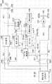
图1为装有根据本发明的实施例的电源系统的车辆的整体框图;1 is an overall block diagram of a vehicle equipped with a power supply system according to an embodiment of the present invention;
图2示出了根据本发明的实施例的PCU的内部构造的实例;Fig. 2 shows the example according to the internal structure of the PCU of the embodiment of the present invention;
图3为一图表,其示出了根据本发明的实施例的DC/DC转换器的输出电力和运行效率之间的相互关系的实例;3 is a graph showing an example of the correlation between output power and operating efficiency of a DC/DC converter according to an embodiment of the present invention;
图4为第一图表,用于示出根据本发明的实施例在外部充电期间在辅机电池上的充电控制的概略;FIG. 4 is a first diagram for illustrating an outline of charge control on an auxiliary battery during external charging according to an embodiment of the present invention;
图5为第二图表,用于示出根据本发明的实施例在外部充电期间在辅机电池上的充电控制的概略;FIG. 5 is a second diagram for illustrating an outline of charge control on an auxiliary battery during external charging according to an embodiment of the present invention;
图6为第三图表,用于示出根据本发明的实施例在外部充电期间在辅机电池上的充电控制的概略;6 is a third diagram for illustrating an outline of charge control on an auxiliary battery during external charging according to an embodiment of the present invention;
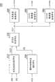
图7为一功能框图,用于示出根据本发明的实施例在外部充电期间在辅机电池上由HV-ECU执行的充电控制;7 is a functional block diagram for illustrating charging control performed by the HV-ECU on the auxiliary battery during external charging according to an embodiment of the present invention;
图8为一流程图,用于示出根据本发明的实施例在外部充电期间在辅机电池上由HV-ECU执行的详细充电控制过程;8 is a flow chart for illustrating a detailed charging control process performed by the HV-ECU on the auxiliary battery during external charging according to an embodiment of the present invention;
图9为装有根据本发明的实施例的替代性实施例的电源系统的车辆的整体框图;以及9 is an overall block diagram of a vehicle equipped with a power supply system according to an alternative embodiment of an embodiment of the present invention; and
图10示出了根据本发明的实施例的整流器电路的内部构造的实例。具体实施方式FIG. 10 shows an example of the internal configuration of a rectifier circuit according to an embodiment of the present invention. Detailed ways
下面将参照附图详细介绍本发明一实施例。注意,相似的参考标号表示相同或对应的部件,不再重复对其进行介绍。Hereinafter, an embodiment of the present invention will be described in detail with reference to the accompanying drawings. Note that like reference numerals designate the same or corresponding components, and their descriptions will not be repeated.
图1为装有根据本发明的实施例的电源系统的车辆100的整体框图。FIG. 1 is an overall block diagram of a
如图1所示,车辆100包含:蓄电装置110;系统主继电器(下面也称为SMR)115;动力控制单元(power control unit)(PCU)120,其用作驱动装置;电动发电机130;动力传送齿轮(power transmission gear)140;驱动轮150和控制器(下面也称为HV-电子控制单元(ECU))300。As shown in FIG. 1 , a
蓄电装置110为电力存储元件,其被配置为可充电以及可放电。蓄电装置110例如由二次电池构成,例如锂离子电池、镍金属氢化物电池和铅酸电池,或者由蓄电元件构成,例如电气双层电容器。The
蓄电装置110经由SMR 115连接到PCU 120,用于驱动电动发电机130。于是,蓄电装置110向PCU 120供给用于产生车辆100的驱动力的电力。另外,蓄电装置110存储由电动发电机130产生的电力。蓄电装置110的输出例如为200V。The
包含在SMR 115中的继电器的一端分别连接到蓄电装置110的正电极端子和负电极端子。包含在SMR 115中的继电器的另一端分别连接到连接到PCU 120的接地线NL1和电力线PL1。于是,SMR 115基于来自HV-ECU 300的控制信号SE1在蓄电装置110和PCU 120之间的电力供给和中断之间进行切换。One end of the relay included in the
图2示出了PCU 120的内部构造的一个实例。如图2所示,PCU 120包含转换器121、变换器122、电容器C1与C2。FIG. 2 shows an example of the internal configuration of the
转换器121基于来自HV-ECU 300的控制信号PWC进行电力线PL1和接地线NL1、电力线HPL和接地线NL1之间的电力转换。Converter 121 performs power conversion between power line PL1 and ground line NL1, power line HPL and ground line NL1 based on control signal PWC from HV-ECU 300.
变换器122被连接到电力线HPL和接地线NL1。基于来自HV-ECU300的控制信号PW1,变换器122将供自转换器121的直流电力转换为交流电力,以便驱动电动发电机130。注意,在当前实施例中,作为实例提供一对电动发电机和变换器,作为替代的是,可提供多对电动发电机和变换器。Inverter 122 is connected to power line HPL and ground line NL1. Based on a control signal PW1 from HV-ECU 300 , inverter 122 converts the DC power supplied from converter 121 into AC power to drive
电容器C1被设置在电力线PL1和接地线NL1之间,以减小电力线PL1和接地线NL1之间的电压的波动。另外,电容器C2被设置在电力线HPL和接地线NL1之间,以便减小电力线HPL和接地线NL1之间的电压波动。Capacitor C1 is provided between power line PL1 and ground line NL1 to reduce fluctuations in voltage between power line PL1 and ground line NL1 . In addition, a capacitor C2 is provided between the power line HPL and the ground line NL1 in order to reduce voltage fluctuations between the power line HPL and the ground line NL1 .
回到图1,电动发电机130为交流旋转电机,例如为永磁型同步电动机,其包含嵌有永磁体的转子。Referring back to FIG. 1 , the
电动发电机130的输出转矩经由动力传送齿轮140被传输到驱动轮150,以便推进车辆100。动力传送齿轮140由减速齿轮和动力分割机构构成。在车辆100的再生制动运行期间,电动发电机130能够使用驱动轮150的旋转力产生电力。于是,所产生的电力被PCU 120转换为充电电力,以便对蓄电装置110进行充电。The output torque of the
另外,在除电动发电机130以外装有发动机(未示出)的混合动力车中,发动机和电动发电机130协同运行,以便产生所需的车辆驱动力。在这种情况下,蓄电装置110可用由发动机的旋转产生的电力充电。Also, in a hybrid vehicle equipped with an engine (not shown) in addition to the
也就是说,根据当前实施例的车辆100为装有用于产生车辆驱动力的电动机的车辆。车辆100包括混合动力车、电气车辆、燃料电池车辆等。混合动力车使用发动机和电动机产生车辆驱动力。电气车辆和燃料电池车辆不具有发动机。That is, the
除了电动发电机130、动力传送齿轮140、驱动轮150以外,图中所示的车辆100的构造的部分构成车辆的电源系统。Except for the
电源系统还包含DC/DC转换器170、辅机电池180和辅机负载190,作为低电压系统(辅机系统)的构造。The power supply system also includes a DC/
DC/DC转换器170被连接到电力线PL1和接地线NL1。基于来自HV-ECU 300的控制信号PWD,DC/DC转换器170对从蓄电装置110供给的直流电压进行降压。于是,DC/DC转换器170经由电力线PL3将电力供到车辆全体的低电压系统,例如辅机电池180、辅机负载190和HV-ECU 300。DC/
辅机电池180典型地由铅酸电池构成。辅机电池180的输出电压低于蓄电装置110的输出电压,例如为大约12V。
例如,辅机负载190包括灯、雨刷、加热器、无线电、导航系统等。For example, auxiliary loads 190 include lights, wipers, heaters, radios, navigation systems, and the like.
HV-ECU 300包含中央处理单元(CPU)、存储装置和输入/输出缓冲器(所有均未在图1中示出)。HV-ECU 300输入来自传感器或类似物的信号,向装置输出控制信号。HV-ECU 300控制车辆100和装置。注意,这些控制不限于软件处理,它们可由专用的硬件(电子电路)处理。The HV-
HV-ECU 300输出用于控制PCU 120、DC/DC转换器170、SMR 115等的控制信号。HV-
HV-ECU 300从包含在蓄电装置110中的传感器(未示出)接收检测到的电压VB1和检测到的电流IB1。HV-ECU 300基于电压VB1和电流IB1计算蓄电装置110的充电状态SOC1。另外,HV-ECU 300接收来自包含在辅机电池180中的传感器(未示出)的检测电压VB2和/或检测电流IB2。HV-ECU 300基于电压VB2和/或电流IB2来计算辅机电池180的充电状态SOC2。HV-
另外,HV-ECU 300接收指示辅机负载190的使用计划和使用状态的信号AUX。信号AUX基于由于到包含在辅机负载190中的装置的驱动信号、所使用的电力等等产生的使用状态以及通过输入单元(未示出)由驾驶者输入的装置的使用计划被设置。在车内蓄电装置正在用车外的电源(下面也简称为“外部电源”)充电(下面也简称为“外部充电”)时,HV-ECU300基于辅机电池180的SOC2以及与辅机负载相关的信号AUX来执行充电控制(其将在后面介绍)。In addition, HV-
电源系统包含充电装置200、AC/DC转换器210、充电ECU 220、充电继电器(CHR)240、连接部分250,作为用于用供自外部电源260的电力对蓄电装置110充电的构造。The power supply system includes charging
充电电缆的充电连接器270被连接到连接部分250。于是,来自外部电源260的电力经由充电电缆被传送到车辆100。A charging
充电装置200经由电力线ACL1、ACL2连接到连接部分250。另外,充电装置200经由CHR 240连接到蓄电装置110。于是,基于来自充电ECU 220的控制信号PWE,充电装置200将供自外部电源260的交流电力转换为直流电力,蓄电装置110可用该直流电力充电。
包含在CHR 240中的继电器的一端分别连接到蓄电装置110的正电极端子和负电极端子。包含在CHR 240中的继电器的另一端分别连接到连接到充电装置200的接地线NL2和电力线PL2。于是,CHR 240基于来自充电ECU 220的控制信号SE2在蓄电装置110和充电装置200间的电力供给和中断之间进行切换。One end of the relay included in
AC/DC转换器210连接到电力线ACL1和ACL2。AC/DC转换器210受到来自HV-ECU 300的控制信号PWF的控制,以便将供自外部电源260的交流电压转换为直流电压。于是,AC/DC转换器210经由电力线PL4将电源电压供到充电ECU 220。另外,电力线PL4也被连接到电力线PL3。于是,在外部充电期间,来自AC/DC转换器210的电力被用于使得对辅机电池180进行充电以及对辅机负载190进行驱动成为可能。AC/DC转换器210基本上用于向充电ECU 220供给电源电压,故AC/DC转换器210的所使用的额定输出低于上面介绍的DC/DC转换器170的额定输出。AC/
充电ECU 220为控制器,用于控制充电装置200和CHR 240。充电ECU 220被配置为可与HV-ECU 300通信。根据来自HV-ECU 300的充电命令CHG,充电ECU 220对充电装置200和CHR 240进行控制,以便进行外部充电。Charging
注意,在图1中,充电ECU 220被设置为与充电装置200分立,然而,充电ECU 220可被包含在控制装置200中。或者,HV-ECU 300可被配置为包含充电ECU 220的功能。Note that, in FIG. Alternatively, HV-
在如此构造的车辆100中,在车辆运行期间,DC/DC转换器170一般恒定运行,以便对辅机电池180进行充电以及对辅机负载190进行驱动。In
甚至在外部充电期间,辅机负载190可能被驾驶者操作,然而,在这种情况下辅机负载190消耗的电力多半低于在车辆运行期间消耗的电力。Even during external charging, the auxiliary load 190 may be operated by the driver, however, the power consumed by the auxiliary load 190 in this case is likely to be lower than that consumed during vehicle operation.
一般使用如上所述具有相对较高容量的DC/DC转换器170,以便在车辆运行期间向辅助系统供给电力。图3为一图表,其示出了运行效率和DC/DC转换器170的输出电力之间的相互关系的实例。在这样的大容量DC/DC转换器中,随着输出电力下降到低于特定的基准值(例如图3中的点P2),运行效率倾向于逐渐降低。于是,如上面所介绍的,在所消耗的电力与车辆运行期间相比较低的外部充电期间,希望尽可能地不运行DC/DC转换器170。A DC/
另一方面,当DC/DC转换器170不运行时,原则上,HV-ECU 300和辅机负载190被供给来自辅机电池180的电源电压。然而,随着电力由HV-ECU 300和辅机负载190消耗,辅机电池180的SOC2逐渐降低。因此,需要对辅机电池180进行充电。On the other hand, when DC/
于是,在当前实施例中,在外部充电期间,基于辅机电池180的充电状态和辅机负载190的状态,执行改变从充电装置200到蓄电装置110的充电电力和从小容量AC/DC转换器210到辅机电池180的充电电力的充电控制。在外部充电期间执行这样的控制,以便使得辅机电池180的充电状态SOC2尽可能地不会变得低于下限阈值。在下限阈值处或在低于下限阈值时,辅机电池180需要由DC/DC转换器170充电。通过这样做,DC/DC转换器170的使用频率降低,以便抑制充电效率的降低。Thus, in the present embodiment, during external charging, changing the charging power from the charging
图4为一图表,示出了在根据当前实施例的外部充电期间在辅机电池上的充电控制的概略。在图4中,横坐标轴代表时间,纵坐标轴代表辅机电池180的充电状态SOC2。FIG. 4 is a graph showing an outline of charge control on the auxiliary battery during external charging according to the present embodiment. In FIG. 4 , the axis of abscissa represents time, and the axis of ordinate represents state of charge SOC2 of
如图1、图4所示,一直到时刻t1,车辆100不运行也不受到外部充电,AC/DC转换器210和DC/DC转换器170停止,辅机电池180的充电状态SOC2也是恒定的。As shown in Fig. 1 and Fig. 4, until the time t1, the
在时刻t1,充电电缆的充电连接器270被连接到车辆100的连接部分,AC/DC转换器210的运行相应地开始。在当前实施例中,在外部充电开始时,首先,辅机电池180在作为主电池的蓄电装置110的充电之前被充电。这是因为下面的原因。At time t1, the charging
一般而言,辅机电池180大部分保持在通常为低电压状态,也就是说,在SOC2相对较低的状态,以便减小由于自放电的损耗并减小内阻。因此,在外部充电开始时,辅机电池180的SOC2多半低,故在蓄电装置110的充电在此状态下开始时,可能在充电开始后立即需要对辅机电池180充电。于是,在某些情况下可能需要运行DC/DC转换器170,故运行可能与通过最小化DC/DC转换器170运行频率来防止充电效率下降的目的相反。因此,在当前实施例中,首先,辅机电池180在外部充电开始后立即被完全充电,此后,开始蓄电装置110的充电,由此,使得DC/DC转换器170的运行频率最小化。In general, the
当辅机电池180在时刻t1与时刻t2之间被AC/DC转换器210充电时,充电装置200不运行,故充电ECU 220也被停止。此时,AC/DC转换器210的输出电力也被设置为最大额定输出电力(例如150W)。通过这样做,几乎所有能由AC/DC转换器210输出的电力可被用作对辅机电池180充电的充电电力(另外,驱动辅机负载190的驱动电力,当辅机负载190被使用时)。When
在AC/DC转换器210对辅机电池180的充电从时刻t1开始后,辅机电池180的充电状态SOC2上升(图4中的线W1)。当充电状态SOC2达到指示满充电的阈值HL时(时刻t2),充电ECU 220根据来自HV-ECU300的充电指令CHG启动。通过这样做,充电装置200对蓄电装置110的充电开始。After AC/
在时刻t2,不需要对辅机电池180充电,AC/DC转换器210的输出电力被设置为驱动充电ECU 200需要的电力(例如100W)。另一方面,充电装置200使用通过将从外部电源260供给的电力(例如1500W)减去AC/DC转换器210使用的电力(也就是说,驱动充电ECU 220需要的电力)获得的电力(例如1400W),以便对蓄电装置110充电。At time t2,
于是,当蓄电装置110的充电在时刻t3完成时,充电装置200的运行和AC/DC转换器210的运行停止。在时刻t3和时刻t4之间,不将充电电力供到辅机电池180,存储在辅机电池180中的电力被辅机负载190以及HV-ECU 300消耗,故SOC2逐渐下降。Then, when the charging of
另外,在图4中,为了比较,虚线W2示出了根据当前实施例的充电控制不应用且蓄电装置110在外部充电在时刻t1开始时马上充电的情况。In addition, in FIG. 4 , for comparison, a dotted line W2 shows a case where charging control according to the present embodiment is not applied and
在这种情况下,在蓄电装置110的充电开始后,没有充电电力被供到辅机电池180,故SOC2逐渐下降。In this case, since charging electric power is not supplied to
此后,在辅机电池180的充电状态SOC2已经下降到指示需要对辅机电池180充电的下限阈值LL时的时间点上(时刻t2A),DC/DC转换器170运行,辅机电池180的充电开始。Thereafter, at a point in time (time t2A) when the state of charge SOC2 of
当辅机电池180的充电在时刻t3A完成时,DC/DC转换器170停止。于是,在时刻t4,蓄电装置110的充电完成。When the charging of
通过这种方式,在图4所示的实例中,应用当前实施例,以便根据辅机电池180的充电状态SOC2调节对蓄电装置110充电的充电电力以及对辅机电池180充电的充电电力,由此使得可以在外部充电期间避免DC/DC转换器170的运行。In this way, in the example shown in FIG. This makes it possible to avoid the operation of the DC/
下面将参照图5、图6来介绍这样的情况:根据当前实施例,在辅机电池180上的充电控制中,在开始蓄电装置110的充电之后,对辅机电池180重新充电。A case where
图5为这样的情况下的时间图:辅机负载190消耗的电力相对较低,可以使用AC/DC转换器210的最大输出电力对辅机电池180进行充电以及对辅机负载190进行驱动。5 is a timing chart in a case where auxiliary load 190 consumes relatively low power and
如图1、图5所示,进行相同的操作,一直到t12,如同图4中一直到t2一样,辅机电池180在对蓄电装置110充电之前被充电。As shown in FIGS. 1 and 5 , the same operation is performed until t12 , and
辅机电池180的充电在时刻t12完成,充电装置200的输出电力增大,优先对蓄电装置110充电。相应地,辅机电池180的SOC2下降,然而,相比于图4,在图5中,辅机负载190消耗的电力高,或者,蓄电装置110的SCO1的水平低,故充电花费时间。因此,在蓄电装置110的充电完成之前,辅机电池180的SOC2下降到另一阈值LL2,其略高于图4中的下限阈值LL1(时刻t13)。Charging of
阈值LL2用于切换到一模式,使得辅机电池180比蓄电装置110更为优先地被充电。在时刻t13,AC/DC转换器210的输出电力被增大到最大额定电力(例如150W)左右。另外,充电装置200的运行和充电ECU 220的运行停止。通过这样做,开始辅机电池180的充电。Threshold LL2 is used to switch to a mode such that
于是,如同在时刻t12的情况一样,当辅机电池180的充电在时刻t14完成时,AC/DC转换器210的输出电力降低到驱动充电ECU 220需要的电力,充电装置200对蓄电装置110的充电被恢复。Then, as in the case of time t12, when the charging of
注意,在时刻13,在充电ECU 220被运行的状态下,在上面的实例中,50W的电力可被供到辅机电池180。如果辅机负载190和HV-ECU 300消耗的电力低于50W,充电装置200的输出电力下降(到例如1350W),使得可以同时对蓄电装置110和辅机电池180充电。Note that at time 13, in the state where charging
图6为这样的情况下的时间图:其中,辅机负载190消耗的电力相对较高(例如200W),AC/DC转换器210的输出电力不满足对辅机电池180充电的电力。FIG. 6 is a timing chart in a case where the power consumed by the auxiliary load 190 is relatively high (for example, 200W), and the output power of the AC/
如图6所示,如同在图4、5的情况下一样,在时刻t21,辅机电池180的充电在对蓄电装置110充电之前开始。然而,在图6的情况下,辅机负载190消耗的电力(例如200W)超过可由AC/DC转换器210供给的电力(例如150W),故辅机电池180不被充电,相反,电力也从辅机电池180输出,以便驱动辅机负载190。因此,SOC2逐渐降低。As shown in FIG. 6 , charging of
在时刻t22,SOC2已经降低到阈值LL2,然而,AC/DC转换器210的最大电力已经被输出,故SOC2进一步降低。于是,在时刻t23,当SOC2已经降低到下限阈值LL1时,DC/DC转换器170被运行,以便对辅机电池180充电(从时刻t23到时刻t24),如同由图4的虚线W2所示的比较性实施例的情况一样。当辅机电池180的充电完成后,DC/DC转换器170停止,蓄电装置110的充电开始。于是,当SOC2在蓄电装置110正在被充电时重新下降到下限阈值LL1时(时刻t25),DC/DC转换器170运行,以便对辅机电池180充电,如同从时刻t23到时刻t24的情况一样(从时刻t25到时刻t26)。注意,在辅机电池180正在用DC/DC转换器170充电时(从时刻t23到时刻t24),蓄电装置110可同时由充电装置200充电。当辅机电池180的充电完成时,蓄电装置110的充电开始,如同时刻t24之后的情况一样。At time t22, SOC2 has decreased to threshold LL2, however, the maximum power of AC/
如同参照图4-图6所介绍的那样,对辅机电池180充电的充电电力和对蓄电装置110充电的充电电力基于辅机电池180的充电状态SOC2以及辅机负载190的使用状态来调节,由此使得可以使DC/DC转换器170的运行最小化,除了如图6所示辅机负载190消耗的电力高的情况以外。结果,在运行效率低的低电力情况下的DC/DC转换器170的运行的频率降低,故可以抑制外部充电期间的充电效率降低。As described with reference to FIGS. 4-6 , the charging power for charging
图7为一功能框图,用于示出根据当前实施例在外部充电期间在辅机电池180上由HV-ECU 300执行的充电控制。图7的功能框图所示的功能框通过HV-ECU 300的软件处理或硬件处理来实现。FIG. 7 is a functional block diagram for illustrating charging control performed by HV-
如图1、图7所示,HV-ECU 300包含充电状态计算单元310、辅机使用状态确定单元320、充电比设置单元330、充电装置控制单元340、AC/DC转换器控制单元350、DC/DC转换器控制单元360。As shown in Figure 1 and Figure 7, the HV-
充电状态计算单元310接收辅机电池180的电压VB2和电流IB2。充电状态计算单元310基于这些信息计算辅机电池180的充电状态(SOC2),并将计算得到的SOC2输出到充电比设置单元330。State of
辅机使用状态确定单元320接收指示辅机负载190的运行计划和运行状态的信号AUX。基于信号AUX,辅机使用状态确定单元320认识到使用状态,包括包含在辅机负载190中的装置的使用计划,以及所消耗的电力。于是,辅机使用状态确定单元320向充电比设置单元330输出与辅机的使用状态相关的信号SIG。The auxiliary machine use
充电比设置单元330从充电状态计算单元310接收充电状态SOC,并从辅机使用状态确定单元320接收辅机的使用状态。基于这些信息,充电比设置单元330设置对辅机电池180充电的充电电力以及蓄电装置110充电的充电电力,并确定DC/DC转换器170是否运行。于是,基于上述结果,充电比设置单元330向充电装置控制单元340、AC/DC转换器控制单元350以及DC/DC转换器控制单元360输出信号RTO,其指示充电装置200、AC/DC转换器210和DC/DC转换器170的输出电力的比。注意,上述比被按照希望地设置为所命令的输出电力与充电装置200、AC/DC转换器210和DC/DC转换器170的相应的额定输出电力的比。The charge
充电装置控制单元340从充电比设置单元330接收信号RTO。于是,充电装置控制单元340基于信号RTO产生用于输出所设置的电力的充电命令CHG,并接着将充电命令CHG输出到充电ECU 220。The charging
AC/DC转换器控制单元350接收来自充电比设置单元330的信号RTO。于是,AC/DC转换器控制单元350基于信号RTO产生用于输出所设置的电力的控制信号PWF,并接着将控制信号PWF输出到AC/DC转换器210。The AC/DC
DC/DC转换器控制单元360接收来自充电比设置单元330的信号RTO。于是,DC/DC转换器控制单元360基于信号RTO产生用于输出所设置的电力的控制信号PWD,并接着将控制信号PWD输出到DC/DC转换器170。The DC/DC
图8为一流程图,用于示出根据当前实施例在外部充电期间在辅机电池180上由HV-ECU 300执行的详细充电控制过程。图8所示的流程图的过程以这样的方式实现:预先存储在HV-ECU 300中的程序由主程序调用,并以预定的间隔执行。或者,所有的步骤或部分步骤的过程可由专用硬件(电子电路)实现。FIG. 8 is a flowchart for showing a detailed charging control process performed by HV-
如图1、图8所示,在步骤(下面,步骤缩写为S)100中,HV-ECU300确定外部电源是否被连接到连接部分250。在步骤S100中,判断仅仅在充电连接器270被首次连接到连接部分250时是肯定的,判断在连接在此后继续的状态下为否。As shown in FIGS. 1 and 8 , in step (hereinafter, step is abbreviated as S) 100 , HV-
当外部电源被首次连接时(S100中的是),S110到S130被跳过,过程进行到S140。于是,HV-ECU 300启动AC/DC转换器210,在对蓄电装置110充电之前开始对辅机电池180充电。When the external power supply is connected for the first time (YES in S100 ), S110 to S130 are skipped, and the process proceeds to S140 . Then, HV-
此后,HV-ECU 300在S150中判断辅机电池180的充电状态SOC2是否高于下限阈值LL1。Thereafter, HV-
当SOC2高于下限阈值LL1时(S150中的是),过程进行到S160,于是,HV-ECU 300判断SOC2是否高于或等于上限阈值HL。When SOC2 is higher than lower threshold LL1 (YES in S150), the process proceeds to S160, whereupon HV-
当SOC2低于下限阈值HL时(S160中的否),HV-ECU 300判断为辅机电池180的充电尚未完成,并将过程返回到S150,以便继续对辅机电池180充电。When SOC2 is lower than lower limit threshold HL (NO in S160), HV-
当SOC2高于或等于上限阈值HL时(S160中的是),HV-ECU 300判断为辅机电池180的充电完成,并将过程返回到主程序。When SOC2 is higher than or equal to upper limit threshold HL (YES in S160), HV-
这里,当SOC2低于或等于下限阈值LL1时(S150中的否),HV-ECU300判断为辅机负载190所消耗的电力高于AC/DC转换器210的额定输出电力,且AC/DC转换器210不能如参照图6所介绍的那样对辅机电池180充电。于是,在S170中,HV-ECU 300运行DC/DC转换器170,并使用从蓄电装置110供给的电力,以便用高于AC/DC转换器210的额定输出电力的电力对辅机电池180充电。此后,过程进行到S160,如上所述地判断辅机电池180的充电是否完成。Here, when SOC2 is lower than or equal to lower limit threshold LL1 (NO in S150 ), HV-
尽管图8没有示出,当DC/DC转换器170运行时,DC/DC转换器170的运行继续,一直到辅机电池180的充电完成,即使在SOC2增大时。Although not shown in FIG. 8, when DC/
另一方面,当外部电源并非第一次连接时(S100中的否),过程进行到S110。于是,HV-ECU 300判断在外部充电期间辅机负载190是否被计划为使用或者辅机负载190是否正在被使用。On the other hand, when the external power supply is not connected for the first time (NO in S100 ), the process proceeds to S110 . Then, HV-
当在外部充电期间辅机负载190被计划为使用或辅机负载190正在被使用时(S110中的是),过程进行到S120,于是,HV-ECU 300判断SOC2是否高于或等于上限阈值,也就是说,辅机电池180是否被完全充电。When auxiliary machine load 190 is scheduled to be used or auxiliary machine load 190 is being used during external charging (YES in S110), the process proceeds to S120, whereupon HV-
当SOC2低于上限阈值(S120中的否)时,过程进行到S130,于是,HV-ECU 300判断SOC2是否高于阈值LL2。When SOC2 is lower than the upper threshold (NO in S120), the process proceeds to S130, whereupon HV-
当SOC2低于或等于阈值LL2(S130中的否)时,HV-ECU 300判断为需要对辅机电池180充电,于是,过程进行到S140。When SOC2 is lower than or equal to threshold LL2 (NO in S130), HV-
在S140中,为了使辅机电池180比蓄电装置110更为优先地充电,HV-ECU 300增大AC/DC转换器210的输出电力,减小充电装置200的输出电力或停止充电装置200,如参照图5、图6所介绍的那样。下面的从S150到S170的过程与上面介绍的相同。In S140, HV-
当辅机负载190既没有在外部充电期间计划为使用又非正在使用时(S110中的否),当SOC2高于或等于上限阈值时(S120中的是)或者当SOC2高于阈值LL2时(S130中的是),HV-ECU 300判断为不需要对辅机电池180充电。于是,过程进行到S180。HV-ECU 300将AC/DC转换器210的输出电力减小到运行充电ECU 220需要的电力,使得蓄电装置110优先被充电装置200充电。另外,HV-ECU 300使得充电装置200的输出电力在外部充电期间车辆100使用的电力不超过可由外部电源260供给的电力的范围内最大化。尽管图中未示出,即使在辅机负载190既没有在外部充电期间计划为使用又非正在使用时(S110中的否),但是当辅机电池180的SOC2低于或等于阈值LL2时,辅机电池180被充电,如同在S140的情况下一样。When the auxiliary load 190 is neither scheduled for use nor in use during external charging (No in S110), when the SOC2 is higher than or equal to the upper threshold (Yes in S120) or when the SOC2 is higher than the threshold LL2 ( Yes in S130), HV-
通过根据上面介绍的过程执行控制,可以基于辅机电池180的充电状态SOC2和辅机负载190的使用状态调节对辅机电池180充电的充电电力和对蓄电装置110充电的充电电力。通过这样做,可以在外部充电期间使得DC/DC转换器170的运行最小化。结果,DC/DC转换器170以运行效率低的低电力运行的频率低,故可以抑制外部充电期间充电效率的降低。By performing control according to the procedure described above, the charging power to charge
替代性实施例alternative embodiment
在上面介绍的实施例中,电力被AC/DC转换器使用来自外部电源的电力供到充电ECU、辅机电池等。In the embodiments described above, electric power is supplied to the charging ECU, the auxiliary battery, etc. by the AC/DC converter using the electric power from the external power source.
顺便提及,用于对蓄电装置充电的某些充电装置包含整流器电路,其将供自外部电源的交流电压转换为直流电压。在这样的充电装置的情况下,代替AC/DC转换器使用对由整流器电路转换的直流电压进行降压的DC/DC转换器也是适用的。Incidentally, some charging devices for charging power storage devices include a rectifier circuit that converts AC voltage supplied from an external power source into DC voltage. In the case of such a charging device, it is also suitable to use a DC/DC converter that steps down a DC voltage converted by a rectifier circuit instead of an AC/DC converter.
在替代性实施例中,将要介绍包含小容量DC/DC转换器而不是AC/DC转换器的构造的实例。In an alternative embodiment, an example of a configuration including a small capacity DC/DC converter instead of an AC/DC converter will be presented.
图9为装有根据对上述实施例的替代性实施例的电源系统的车辆100A的整体框图。在图9中,根据上面的实施例的图1所示配置中的充电装置200用充电装置200A代替,提供小容量DC/DC转换器210A而不是AC/DC转换器210。在图9中,对与图1中的重叠的元件的介绍不再重复。FIG. 9 is an overall block diagram of a
如图9所示,充电装置200A包含整流器电路201和DC/DC转换器202。整流器电路201经由电力线ACL1和ACL2连接到连接部分250。整流器电路201将供自外部电源260的交流电压整流为直流电压,并将直流电压输出到电力线PL5和接地线NL5。As shown in FIG. 9 , charging
图10示出了整流器电路201的内部结构的实例。整流器电路201包含电抗器L1和L2、二极管桥203和电容器C10。二极管桥203包含二极管D1-D4。FIG. 10 shows an example of the internal structure of the
二极管桥203被构建为使得串联连接的二极管D1和D2以及串联连接的二极管D3和D4彼此并联地连接到电力线PL5和接地线NL5。
电抗器L1的一端连接到二极管D1和D2的连接节点,电抗器L1的另一端连接到电力线ACL1。另外,电抗器L2的一端连接到二极管D3、D4的连接节点,电抗器L2的另一端连接到电力线ACL2。One end of reactor L1 is connected to a connection node of diodes D1 and D2 , and the other end of reactor L1 is connected to power line ACL1 . In addition, one end of reactor L2 is connected to the connection node of diodes D3 and D4, and the other end of reactor L2 is connected to power line ACL2.
电容器C10与二极管桥203并联连接在电力线PL5和接地线NL5之间,降低电力线PL5和接地线NL5之间的电压的波动。Capacitor C10 is connected in parallel with
使用上面的构造,整流器电路201将供自外部电源260的交流电压整流为直流电压。注意,整流器电路201的构造不限于图10所示的构造,只要其为能够将交流电压转换为直流电压的电路。作为另一整流器电路的实例,整流器电路的构造可以为例如全桥装换器或半桥转换器,然而,整流器电路可如图10所示地按照希望配置,以便不需要特别的控制,从而使用简单的配置而不增加控制负担。With the above configuration, the
回到图9,DC/DC转换器202经由电力线PL5和接地线NL5被连接到整流器电路201。另外,DC/DC转换器202经由CHR 240由电力线PL2和接地线NL2连接到蓄电装置110。DC/DC转换器202受到来自控制ECU220的控制信号PWE的控制。DC/DC转换器202对从整流器电路201输出的直流电压进行转换,并将充电电力供到蓄电装置110。Returning to FIG. 9 , the DC/
DC/DC转换器210A被连接到电力线PL5和接地线NL5。DC/DC转换器210A受到来自HV-ECU 300的控制信号PWF的控制。DC/DC转换器210A对从整流器电路201输出的直流电压进行降压,并将直流电压输出到电力线PL4。DC/
使用上面的构造,通过执行与上面的实施例相同的控制,高容量DC/DC转换器170的运行在外部充电期间最小化,由此使得可以抑制外部充电期间的充电效率下降。With the above configuration, by performing the same control as the above embodiment, the operation of high-capacity DC/
注意,根据上面的实施例的充电ECU 220和HV-ECU 300为根据本发明的实施形态的控制器的实例。根据上面的实施例的蓄电装置110和辅机电池180分别为根据本发明的实施形态的第一蓄电装置的实例和根据本发明的实施形态的第二蓄电装置的实例。根据上面的实施例的DC/DC转换器170为根据本发明的实施形态的第一转换器的实例。根据上面的实施例的AC/DC转换器210和DC/DC转换器210A为根据本发明的实施形态的第二转换器的实例。Note that charging
上面介绍的实施例在所有方面是说明性而不是限制性的。本发明的范围由所附权利要求书而不是上面的说明书限定。本发明的范围旨在包括落在所附权利要求及其等价内容的范围内的所有变型。The embodiments described above are illustrative and not restrictive in all respects. The scope of the invention is defined by the appended claims rather than the above description. The scope of the present invention is intended to embrace all modifications that come within the scope of the appended claims and equivalents thereof.
Claims (9)
Translated fromChineseApplications Claiming Priority (3)
| Application Number | Priority Date | Filing Date | Title |
|---|---|---|---|
| JP2010093250AJP5168308B2 (en) | 2010-04-14 | 2010-04-14 | Power supply system and vehicle equipped with the same |
| JP093250/2010 | 2010-04-14 | ||
| PCT/IB2011/000758WO2011128750A2 (en) | 2010-04-14 | 2011-04-07 | Power supply system and vehicle equipped with power supply system |
Publications (2)
| Publication Number | Publication Date |
|---|---|
| CN102844220A CN102844220A (en) | 2012-12-26 |
| CN102844220Btrue CN102844220B (en) | 2014-05-07 |
Family
ID=44626714
Family Applications (1)
| Application Number | Title | Priority Date | Filing Date |
|---|---|---|---|
| CN201180018479.6AActiveCN102844220B (en) | 2010-04-14 | 2011-04-07 | Power supply system and vehicle equipped with power supply system |
Country Status (5)
| Country | Link |
|---|---|
| US (1) | US9007001B2 (en) |
| EP (1) | EP2558329B1 (en) |
| JP (1) | JP5168308B2 (en) |
| CN (1) | CN102844220B (en) |
| WO (1) | WO2011128750A2 (en) |
Families Citing this family (38)
| Publication number | Priority date | Publication date | Assignee | Title |
|---|---|---|---|---|
| EP2698270B1 (en)* | 2011-04-13 | 2016-11-16 | Toyota Jidosha Kabushiki Kaisha | Power source apparatus for electrically powered vehicle and control method therefor |
| CN103561999B (en)* | 2011-05-27 | 2016-07-06 | 丰田自动车株式会社 | vehicle |
| WO2013065169A1 (en)* | 2011-11-04 | 2013-05-10 | トヨタ自動車株式会社 | Power source system and vehicle provided therewith, and method of controlling power source system |
| KR101305605B1 (en) | 2011-11-25 | 2013-09-09 | 엘에스산전 주식회사 | Electric Vehicle Power Supply System |
| JP5886734B2 (en)* | 2012-01-10 | 2016-03-16 | 本田技研工業株式会社 | Electric vehicle |
| KR101369052B1 (en)* | 2012-05-21 | 2014-03-04 | 엘에스산전 주식회사 | Inverter-charger combined device for electric vehicles |
| US8981727B2 (en) | 2012-05-21 | 2015-03-17 | General Electric Company | Method and apparatus for charging multiple energy storage devices |
| CN103660967A (en) | 2012-09-24 | 2014-03-26 | 通用电气公司 | Mobile transportation equipment with improved energy supplying mechanism and mobile transportation method |
| JP2014158414A (en)* | 2013-01-21 | 2014-08-28 | Semiconductor Energy Lab Co Ltd | Vehicle having power storage body |
| JP2014176170A (en)* | 2013-03-07 | 2014-09-22 | Toshiba Corp | Power incoming apparatus and charging system |
| US9707856B2 (en)* | 2013-03-11 | 2017-07-18 | Mitsubishi Electric Corporation | Vehicle power management device |
| JP5741635B2 (en) | 2013-06-17 | 2015-07-01 | 三菱自動車工業株式会社 | Auxiliary battery power supply device |
| DE102013219360A1 (en)* | 2013-09-26 | 2015-03-26 | Siemens Aktiengesellschaft | Energy storage device |
| JP5850017B2 (en) | 2013-10-15 | 2016-02-03 | 株式会社デンソー | Battery monitoring device |
| KR102280579B1 (en)* | 2013-12-19 | 2021-07-22 | 삼성전자주식회사 | Charge circuit, Charge system and wireless power receiver |
| CN106165240B (en)* | 2014-03-03 | 2018-09-21 | 罗伯特·博世有限公司 | Topology for mixing storage system and control strategy |
| DE102014209249A1 (en)* | 2014-05-15 | 2015-11-19 | Ford Global Technologies, Llc | Electric charging method for a vehicle and an electric vehicle charging device |
| US9821738B2 (en) | 2014-06-30 | 2017-11-21 | Raymond Anthony Joao | Battery power management apparatus and method |
| DE102014016620B4 (en)* | 2014-10-24 | 2021-08-26 | Audi Ag | Method for operating an energy storage device in a motor vehicle and motor vehicle |
| JP6183411B2 (en)* | 2015-05-26 | 2017-08-23 | トヨタ自動車株式会社 | vehicle |
| JP6269647B2 (en)* | 2015-12-14 | 2018-01-31 | トヨタ自動車株式会社 | Power system |
| US11951769B2 (en) | 2016-01-29 | 2024-04-09 | Semiconductor Energy Laboratory Co., Ltd. | Electric power control system |
| US10128786B2 (en)* | 2017-01-13 | 2018-11-13 | Ford Global Technologies, Llc | Electric vehicle electric drive system |
| CN107017674A (en)* | 2017-04-12 | 2017-08-04 | 蔚来汽车有限公司 | Electric mobile charging vehicle and charging and discharging method based on same |
| EP3671922A4 (en)* | 2017-08-14 | 2020-08-12 | Nissan Motor Co., Ltd. | POWER SUPPLY SYSTEM AND CONTROL PROCEDURES FOR IT |
| JP2019062711A (en)* | 2017-09-28 | 2019-04-18 | 株式会社デンソー | On-vehicle auxiliary machine device |
| JP7010035B2 (en)* | 2018-02-06 | 2022-01-26 | トヨタ自動車株式会社 | Electric vehicle |
| JP7102781B2 (en)* | 2018-02-28 | 2022-07-20 | 株式会社デンソー | Control device |
| JP2019154203A (en)* | 2018-03-06 | 2019-09-12 | トヨタ自動車株式会社 | Electric vehicle charging control device |
| JP7433748B2 (en)* | 2018-05-31 | 2024-02-20 | 矢崎総業株式会社 | power supply unit |
| JP7003855B2 (en)* | 2018-07-05 | 2022-01-21 | 株式会社オートネットワーク技術研究所 | Power system |
| JP2020043708A (en)* | 2018-09-12 | 2020-03-19 | 本田技研工業株式会社 | Power supply |
| JP7382822B2 (en)* | 2019-12-25 | 2023-11-17 | 京セラ株式会社 | RFID tag |
| JP7439663B2 (en)* | 2020-07-07 | 2024-02-28 | トヨタ自動車株式会社 | Vehicle control device, method, program, and vehicle |
| US11929632B2 (en) | 2021-01-27 | 2024-03-12 | Livewire Ev, Llc | On-board charger system with integrated auxiliary power supply |
| US11760227B2 (en) | 2021-02-15 | 2023-09-19 | Raymond Anthony Joao | Battery power management apparatus and method |
| KR20230020165A (en)* | 2021-08-03 | 2023-02-10 | 현대자동차주식회사 | Mobile electric vehicle charging system |
| FR3154660A1 (en)* | 2023-10-26 | 2025-05-02 | Alstom Holdings | VEHICLE DRIVE SYSTEM AND CHARGING METHOD |
Citations (2)
| Publication number | Priority date | Publication date | Assignee | Title |
|---|---|---|---|---|
| CN101682202A (en)* | 2007-06-06 | 2010-03-24 | 丰田自动车株式会社 | Power supply unit of vehicle |
| CN101689768A (en)* | 2007-07-18 | 2010-03-31 | 丰田自动车株式会社 | Power supply unit of vehicle |
Family Cites Families (18)
| Publication number | Priority date | Publication date | Assignee | Title |
|---|---|---|---|---|
| JP2850922B2 (en)* | 1991-04-25 | 1999-01-27 | 株式会社デンソー | DC / DC converter for electric vehicles |
| JPH0715807A (en)* | 1993-06-25 | 1995-01-17 | Sanden Corp | Power source unit for electric vehicle |
| JP3245334B2 (en)* | 1995-08-03 | 2002-01-15 | 本田技研工業株式会社 | Power control device for electric vehicle |
| JPH11164409A (en)* | 1997-11-27 | 1999-06-18 | Suzuki Motor Corp | Method for controlling charging of battery for electric vehicle and its device |
| JP3840057B2 (en)* | 2001-02-28 | 2006-11-01 | 松下電工株式会社 | Charger |
| JP4144646B1 (en)* | 2007-02-20 | 2008-09-03 | トヨタ自動車株式会社 | Electric vehicle, vehicle charging device, and vehicle charging system |
| JP2009027774A (en) | 2007-07-17 | 2009-02-05 | Toyota Motor Corp | vehicle |
| JP4586832B2 (en)* | 2007-08-10 | 2010-11-24 | トヨタ自動車株式会社 | Electric vehicle |
| JP4640391B2 (en)* | 2007-08-10 | 2011-03-02 | トヨタ自動車株式会社 | Power supply system and vehicle equipped with the same |
| JP4479768B2 (en)* | 2007-09-10 | 2010-06-09 | トヨタ自動車株式会社 | Automobile and auto charging method |
| JP4893653B2 (en)* | 2008-02-19 | 2012-03-07 | トヨタ自動車株式会社 | Vehicle, rechargeable battery state of charge estimation method and vehicle control method |
| JP4315232B1 (en)* | 2008-03-17 | 2009-08-19 | トヨタ自動車株式会社 | Electric vehicle |
| JP4488090B2 (en)* | 2008-06-09 | 2010-06-23 | トヨタ自動車株式会社 | Vehicle and vehicle control method |
| JP4715881B2 (en)* | 2008-07-25 | 2011-07-06 | トヨタ自動車株式会社 | Power supply system and vehicle equipped with the same |
| JP4957873B2 (en)* | 2009-08-07 | 2012-06-20 | トヨタ自動車株式会社 | Electric vehicle power supply system and control method thereof |
| DE112009005181B4 (en) | 2009-08-28 | 2018-08-23 | Toyota Jidosha Kabushiki Kaisha | Energy supply system for a vehicle and electrically driven vehicle with the energy supply system |
| JP5487817B2 (en)* | 2009-09-04 | 2014-05-14 | 株式会社オートネットワーク技術研究所 | Auxiliary battery power supply system and auxiliary battery power supply method |
| WO2011036758A1 (en)* | 2009-09-25 | 2011-03-31 | トヨタ自動車株式会社 | Vehicle charging system and electric vehicle equipped with same |
- 2010
- 2010-04-14JPJP2010093250Apatent/JP5168308B2/enactiveActive
- 2011
- 2011-04-07CNCN201180018479.6Apatent/CN102844220B/enactiveActive
- 2011-04-07EPEP11723619.0Apatent/EP2558329B1/enactiveActive
- 2011-04-07WOPCT/IB2011/000758patent/WO2011128750A2/enactiveApplication Filing
- 2011-04-07USUS13/640,376patent/US9007001B2/enactiveActive
Patent Citations (2)
| Publication number | Priority date | Publication date | Assignee | Title |
|---|---|---|---|---|
| CN101682202A (en)* | 2007-06-06 | 2010-03-24 | 丰田自动车株式会社 | Power supply unit of vehicle |
| CN101689768A (en)* | 2007-07-18 | 2010-03-31 | 丰田自动车株式会社 | Power supply unit of vehicle |
Also Published As
| Publication number | Publication date |
|---|---|
| WO2011128750A3 (en) | 2012-01-05 |
| WO2011128750A2 (en) | 2011-10-20 |
| EP2558329B1 (en) | 2014-03-12 |
| CN102844220A (en) | 2012-12-26 |
| US9007001B2 (en) | 2015-04-14 |
| EP2558329A2 (en) | 2013-02-20 |
| JP5168308B2 (en) | 2013-03-21 |
| JP2011223834A (en) | 2011-11-04 |
| US20130134908A1 (en) | 2013-05-30 |
Similar Documents
| Publication | Publication Date | Title |
|---|---|---|
| CN102844220B (en) | Power supply system and vehicle equipped with power supply system | |
| CN102834280B (en) | Power supply system and vehicle equipped with power supply system | |
| JP5459408B2 (en) | Power supply system for electric vehicle, control method therefor, and electric vehicle | |
| CN103339005B (en) | Hybrid vehicle | |
| CN103221246B (en) | vehicle charging device | |
| CN102858582B (en) | Power supply device for electric vehicle and control method thereof | |
| RU2453455C1 (en) | Hybrid transport facility, method of controlling its electric power system | |
| CN103889777B (en) | Including the vehicle of secondary cell with for including the control method of the vehicle of secondary cell | |
| CN103492214B (en) | The supply unit of elec. vehicle and control method thereof | |
| JP5131355B2 (en) | Hybrid vehicle | |
| CN102470770A (en) | Power supply system of electrically driven vehicle | |
| WO2010050038A1 (en) | Power supply system for electric vehicle and control method for the same | |
| JP2014143817A (en) | Vehicle power system | |
| WO2010050045A1 (en) | Electromotive vehicle power supply system, electromotive vehicle, and electromotive vehicle control method | |
| US20160257296A1 (en) | Controller for hybrid vehicle | |
| CN112895933B (en) | Vehicles and vehicle control methods | |
| WO2012063330A1 (en) | Power feeding device and power feeding method |
Legal Events
| Date | Code | Title | Description |
|---|---|---|---|
| C06 | Publication | ||
| PB01 | Publication | ||
| C10 | Entry into substantive examination | ||
| SE01 | Entry into force of request for substantive examination | ||
| C14 | Grant of patent or utility model | ||
| GR01 | Patent grant |