CN102844176A - Selective Adhesion Reduction in Microfluidic Devices - Google Patents
Selective Adhesion Reduction in Microfluidic DevicesDownload PDFInfo
- Publication number
- CN102844176A CN102844176ACN2010800543686ACN201080054368ACN102844176ACN 102844176 ACN102844176 ACN 102844176ACN 2010800543686 ACN2010800543686 ACN 2010800543686ACN 201080054368 ACN201080054368 ACN 201080054368ACN 102844176 ACN102844176 ACN 102844176A
- Authority
- CN
- China
- Prior art keywords
- bonding
- flow cell
- bond
- detection flow
- microfluidic
- Prior art date
- Legal status (The legal status is an assumption and is not a legal conclusion. Google has not performed a legal analysis and makes no representation as to the accuracy of the status listed.)
- Pending
Links
Images


Classifications
- F—MECHANICAL ENGINEERING; LIGHTING; HEATING; WEAPONS; BLASTING
- F04—POSITIVE - DISPLACEMENT MACHINES FOR LIQUIDS; PUMPS FOR LIQUIDS OR ELASTIC FLUIDS
- F04B—POSITIVE-DISPLACEMENT MACHINES FOR LIQUIDS; PUMPS
- F04B19/00—Machines or pumps having pertinent characteristics not provided for in, or of interest apart from, groups F04B1/00 - F04B17/00
- F04B19/006—Micropumps
- B—PERFORMING OPERATIONS; TRANSPORTING
- B01—PHYSICAL OR CHEMICAL PROCESSES OR APPARATUS IN GENERAL
- B01L—CHEMICAL OR PHYSICAL LABORATORY APPARATUS FOR GENERAL USE
- B01L3/00—Containers or dishes for laboratory use, e.g. laboratory glassware; Droppers
- B01L3/50—Containers for the purpose of retaining a material to be analysed, e.g. test tubes
- B01L3/502—Containers for the purpose of retaining a material to be analysed, e.g. test tubes with fluid transport, e.g. in multi-compartment structures
- B01L3/5027—Containers for the purpose of retaining a material to be analysed, e.g. test tubes with fluid transport, e.g. in multi-compartment structures by integrated microfluidic structures, i.e. dimensions of channels and chambers are such that surface tension forces are important, e.g. lab-on-a-chip
- B01L3/502707—Containers for the purpose of retaining a material to be analysed, e.g. test tubes with fluid transport, e.g. in multi-compartment structures by integrated microfluidic structures, i.e. dimensions of channels and chambers are such that surface tension forces are important, e.g. lab-on-a-chip characterised by the manufacture of the container or its components
- B—PERFORMING OPERATIONS; TRANSPORTING
- B01—PHYSICAL OR CHEMICAL PROCESSES OR APPARATUS IN GENERAL
- B01L—CHEMICAL OR PHYSICAL LABORATORY APPARATUS FOR GENERAL USE
- B01L3/00—Containers or dishes for laboratory use, e.g. laboratory glassware; Droppers
- B01L3/50—Containers for the purpose of retaining a material to be analysed, e.g. test tubes
- B01L3/502—Containers for the purpose of retaining a material to be analysed, e.g. test tubes with fluid transport, e.g. in multi-compartment structures
- B01L3/5027—Containers for the purpose of retaining a material to be analysed, e.g. test tubes with fluid transport, e.g. in multi-compartment structures by integrated microfluidic structures, i.e. dimensions of channels and chambers are such that surface tension forces are important, e.g. lab-on-a-chip
- B01L3/502738—Containers for the purpose of retaining a material to be analysed, e.g. test tubes with fluid transport, e.g. in multi-compartment structures by integrated microfluidic structures, i.e. dimensions of channels and chambers are such that surface tension forces are important, e.g. lab-on-a-chip characterised by integrated valves
- B—PERFORMING OPERATIONS; TRANSPORTING
- B29—WORKING OF PLASTICS; WORKING OF SUBSTANCES IN A PLASTIC STATE IN GENERAL
- B29C—SHAPING OR JOINING OF PLASTICS; SHAPING OF MATERIAL IN A PLASTIC STATE, NOT OTHERWISE PROVIDED FOR; AFTER-TREATMENT OF THE SHAPED PRODUCTS, e.g. REPAIRING
- B29C65/00—Joining or sealing of preformed parts, e.g. welding of plastics materials; Apparatus therefor
- B29C65/48—Joining or sealing of preformed parts, e.g. welding of plastics materials; Apparatus therefor using adhesives, i.e. using supplementary joining material; solvent bonding
- B—PERFORMING OPERATIONS; TRANSPORTING
- B29—WORKING OF PLASTICS; WORKING OF SUBSTANCES IN A PLASTIC STATE IN GENERAL
- B29C—SHAPING OR JOINING OF PLASTICS; SHAPING OF MATERIAL IN A PLASTIC STATE, NOT OTHERWISE PROVIDED FOR; AFTER-TREATMENT OF THE SHAPED PRODUCTS, e.g. REPAIRING
- B29C66/00—General aspects of processes or apparatus for joining preformed parts
- B29C66/004—Preventing sticking together, e.g. of some areas of the parts to be joined
- B—PERFORMING OPERATIONS; TRANSPORTING
- B32—LAYERED PRODUCTS
- B32B—LAYERED PRODUCTS, i.e. PRODUCTS BUILT-UP OF STRATA OF FLAT OR NON-FLAT, e.g. CELLULAR OR HONEYCOMB, FORM
- B32B37/00—Methods or apparatus for laminating, e.g. by curing or by ultrasonic bonding
- B32B37/0076—Methods or apparatus for laminating, e.g. by curing or by ultrasonic bonding characterised in that the layers are not bonded on the totality of their surfaces
- F—MECHANICAL ENGINEERING; LIGHTING; HEATING; WEAPONS; BLASTING
- F16—ENGINEERING ELEMENTS AND UNITS; GENERAL MEASURES FOR PRODUCING AND MAINTAINING EFFECTIVE FUNCTIONING OF MACHINES OR INSTALLATIONS; THERMAL INSULATION IN GENERAL
- F16K—VALVES; TAPS; COCKS; ACTUATING-FLOATS; DEVICES FOR VENTING OR AERATING
- F16K99/00—Subject matter not provided for in other groups of this subclass
- F16K99/0001—Microvalves
- B—PERFORMING OPERATIONS; TRANSPORTING
- B01—PHYSICAL OR CHEMICAL PROCESSES OR APPARATUS IN GENERAL
- B01L—CHEMICAL OR PHYSICAL LABORATORY APPARATUS FOR GENERAL USE
- B01L2200/00—Solutions for specific problems relating to chemical or physical laboratory apparatus
- B01L2200/06—Fluid handling related problems
- B01L2200/0689—Sealing
- B—PERFORMING OPERATIONS; TRANSPORTING
- B01—PHYSICAL OR CHEMICAL PROCESSES OR APPARATUS IN GENERAL
- B01L—CHEMICAL OR PHYSICAL LABORATORY APPARATUS FOR GENERAL USE
- B01L2300/00—Additional constructional details
- B01L2300/06—Auxiliary integrated devices, integrated components
- B01L2300/0627—Sensor or part of a sensor is integrated
- B01L2300/0636—Integrated biosensor, microarrays
- B—PERFORMING OPERATIONS; TRANSPORTING
- B01—PHYSICAL OR CHEMICAL PROCESSES OR APPARATUS IN GENERAL
- B01L—CHEMICAL OR PHYSICAL LABORATORY APPARATUS FOR GENERAL USE
- B01L2300/00—Additional constructional details
- B01L2300/06—Auxiliary integrated devices, integrated components
- B01L2300/0681—Filter
- B—PERFORMING OPERATIONS; TRANSPORTING
- B01—PHYSICAL OR CHEMICAL PROCESSES OR APPARATUS IN GENERAL
- B01L—CHEMICAL OR PHYSICAL LABORATORY APPARATUS FOR GENERAL USE
- B01L2300/00—Additional constructional details
- B01L2300/06—Auxiliary integrated devices, integrated components
- B01L2300/069—Absorbents; Gels to retain a fluid
- B—PERFORMING OPERATIONS; TRANSPORTING
- B01—PHYSICAL OR CHEMICAL PROCESSES OR APPARATUS IN GENERAL
- B01L—CHEMICAL OR PHYSICAL LABORATORY APPARATUS FOR GENERAL USE
- B01L2300/00—Additional constructional details
- B01L2300/08—Geometry, shape and general structure
- B01L2300/0809—Geometry, shape and general structure rectangular shaped
- B01L2300/0816—Cards, e.g. flat sample carriers usually with flow in two horizontal directions
- B—PERFORMING OPERATIONS; TRANSPORTING
- B01—PHYSICAL OR CHEMICAL PROCESSES OR APPARATUS IN GENERAL
- B01L—CHEMICAL OR PHYSICAL LABORATORY APPARATUS FOR GENERAL USE
- B01L2300/00—Additional constructional details
- B01L2300/08—Geometry, shape and general structure
- B01L2300/0861—Configuration of multiple channels and/or chambers in a single devices
- B01L2300/0864—Configuration of multiple channels and/or chambers in a single devices comprising only one inlet and multiple receiving wells, e.g. for separation, splitting
- B—PERFORMING OPERATIONS; TRANSPORTING
- B01—PHYSICAL OR CHEMICAL PROCESSES OR APPARATUS IN GENERAL
- B01L—CHEMICAL OR PHYSICAL LABORATORY APPARATUS FOR GENERAL USE
- B01L2300/00—Additional constructional details
- B01L2300/08—Geometry, shape and general structure
- B01L2300/0861—Configuration of multiple channels and/or chambers in a single devices
- B01L2300/0867—Multiple inlets and one sample wells, e.g. mixing, dilution
- B—PERFORMING OPERATIONS; TRANSPORTING
- B01—PHYSICAL OR CHEMICAL PROCESSES OR APPARATUS IN GENERAL
- B01L—CHEMICAL OR PHYSICAL LABORATORY APPARATUS FOR GENERAL USE
- B01L2300/00—Additional constructional details
- B01L2300/08—Geometry, shape and general structure
- B01L2300/0887—Laminated structure
- B—PERFORMING OPERATIONS; TRANSPORTING
- B01—PHYSICAL OR CHEMICAL PROCESSES OR APPARATUS IN GENERAL
- B01L—CHEMICAL OR PHYSICAL LABORATORY APPARATUS FOR GENERAL USE
- B01L2400/00—Moving or stopping fluids
- B01L2400/06—Valves, specific forms thereof
- B01L2400/0605—Valves, specific forms thereof check valves
- B—PERFORMING OPERATIONS; TRANSPORTING
- B01—PHYSICAL OR CHEMICAL PROCESSES OR APPARATUS IN GENERAL
- B01L—CHEMICAL OR PHYSICAL LABORATORY APPARATUS FOR GENERAL USE
- B01L2400/00—Moving or stopping fluids
- B01L2400/06—Valves, specific forms thereof
- B01L2400/0633—Valves, specific forms thereof with moving parts
- B01L2400/0638—Valves, specific forms thereof with moving parts membrane valves, flap valves
- B—PERFORMING OPERATIONS; TRANSPORTING
- B01—PHYSICAL OR CHEMICAL PROCESSES OR APPARATUS IN GENERAL
- B01L—CHEMICAL OR PHYSICAL LABORATORY APPARATUS FOR GENERAL USE
- B01L2400/00—Moving or stopping fluids
- B01L2400/06—Valves, specific forms thereof
- B01L2400/0677—Valves, specific forms thereof phase change valves; Meltable, freezing, dissolvable plugs; Destructible barriers
- B01L2400/0683—Valves, specific forms thereof phase change valves; Meltable, freezing, dissolvable plugs; Destructible barriers mechanically breaking a wall or membrane within a channel or chamber
- B—PERFORMING OPERATIONS; TRANSPORTING
- B01—PHYSICAL OR CHEMICAL PROCESSES OR APPARATUS IN GENERAL
- B01L—CHEMICAL OR PHYSICAL LABORATORY APPARATUS FOR GENERAL USE
- B01L3/00—Containers or dishes for laboratory use, e.g. laboratory glassware; Droppers
- B01L3/50—Containers for the purpose of retaining a material to be analysed, e.g. test tubes
- B01L3/502—Containers for the purpose of retaining a material to be analysed, e.g. test tubes with fluid transport, e.g. in multi-compartment structures
- B01L3/5023—Containers for the purpose of retaining a material to be analysed, e.g. test tubes with fluid transport, e.g. in multi-compartment structures with a sample being transported to, and subsequently stored in an absorbent for analysis
- B—PERFORMING OPERATIONS; TRANSPORTING
- B29—WORKING OF PLASTICS; WORKING OF SUBSTANCES IN A PLASTIC STATE IN GENERAL
- B29C—SHAPING OR JOINING OF PLASTICS; SHAPING OF MATERIAL IN A PLASTIC STATE, NOT OTHERWISE PROVIDED FOR; AFTER-TREATMENT OF THE SHAPED PRODUCTS, e.g. REPAIRING
- B29C65/00—Joining or sealing of preformed parts, e.g. welding of plastics materials; Apparatus therefor
- B29C65/002—Joining methods not otherwise provided for
- B29C65/006—Diffusion joining
- B—PERFORMING OPERATIONS; TRANSPORTING
- B29—WORKING OF PLASTICS; WORKING OF SUBSTANCES IN A PLASTIC STATE IN GENERAL
- B29C—SHAPING OR JOINING OF PLASTICS; SHAPING OF MATERIAL IN A PLASTIC STATE, NOT OTHERWISE PROVIDED FOR; AFTER-TREATMENT OF THE SHAPED PRODUCTS, e.g. REPAIRING
- B29C65/00—Joining or sealing of preformed parts, e.g. welding of plastics materials; Apparatus therefor
- B29C65/002—Joining methods not otherwise provided for
- B29C65/008—Joining methods not otherwise provided for making use of electrostatic charges
- B—PERFORMING OPERATIONS; TRANSPORTING
- B29—WORKING OF PLASTICS; WORKING OF SUBSTANCES IN A PLASTIC STATE IN GENERAL
- B29C—SHAPING OR JOINING OF PLASTICS; SHAPING OF MATERIAL IN A PLASTIC STATE, NOT OTHERWISE PROVIDED FOR; AFTER-TREATMENT OF THE SHAPED PRODUCTS, e.g. REPAIRING
- B29C65/00—Joining or sealing of preformed parts, e.g. welding of plastics materials; Apparatus therefor
- B29C65/02—Joining or sealing of preformed parts, e.g. welding of plastics materials; Apparatus therefor by heating, with or without pressure
- B29C65/08—Joining or sealing of preformed parts, e.g. welding of plastics materials; Apparatus therefor by heating, with or without pressure using ultrasonic vibrations
- B—PERFORMING OPERATIONS; TRANSPORTING
- B29—WORKING OF PLASTICS; WORKING OF SUBSTANCES IN A PLASTIC STATE IN GENERAL
- B29C—SHAPING OR JOINING OF PLASTICS; SHAPING OF MATERIAL IN A PLASTIC STATE, NOT OTHERWISE PROVIDED FOR; AFTER-TREATMENT OF THE SHAPED PRODUCTS, e.g. REPAIRING
- B29C65/00—Joining or sealing of preformed parts, e.g. welding of plastics materials; Apparatus therefor
- B29C65/02—Joining or sealing of preformed parts, e.g. welding of plastics materials; Apparatus therefor by heating, with or without pressure
- B29C65/14—Joining or sealing of preformed parts, e.g. welding of plastics materials; Apparatus therefor by heating, with or without pressure using wave energy, i.e. electromagnetic radiation, or particle radiation
- B29C65/1403—Joining or sealing of preformed parts, e.g. welding of plastics materials; Apparatus therefor by heating, with or without pressure using wave energy, i.e. electromagnetic radiation, or particle radiation characterised by the type of electromagnetic or particle radiation
- B29C65/1406—Ultraviolet [UV] radiation
- B—PERFORMING OPERATIONS; TRANSPORTING
- B29—WORKING OF PLASTICS; WORKING OF SUBSTANCES IN A PLASTIC STATE IN GENERAL
- B29C—SHAPING OR JOINING OF PLASTICS; SHAPING OF MATERIAL IN A PLASTIC STATE, NOT OTHERWISE PROVIDED FOR; AFTER-TREATMENT OF THE SHAPED PRODUCTS, e.g. REPAIRING
- B29C65/00—Joining or sealing of preformed parts, e.g. welding of plastics materials; Apparatus therefor
- B29C65/02—Joining or sealing of preformed parts, e.g. welding of plastics materials; Apparatus therefor by heating, with or without pressure
- B29C65/14—Joining or sealing of preformed parts, e.g. welding of plastics materials; Apparatus therefor by heating, with or without pressure using wave energy, i.e. electromagnetic radiation, or particle radiation
- B29C65/1403—Joining or sealing of preformed parts, e.g. welding of plastics materials; Apparatus therefor by heating, with or without pressure using wave energy, i.e. electromagnetic radiation, or particle radiation characterised by the type of electromagnetic or particle radiation
- B29C65/1409—Visible light radiation
- B—PERFORMING OPERATIONS; TRANSPORTING
- B29—WORKING OF PLASTICS; WORKING OF SUBSTANCES IN A PLASTIC STATE IN GENERAL
- B29C—SHAPING OR JOINING OF PLASTICS; SHAPING OF MATERIAL IN A PLASTIC STATE, NOT OTHERWISE PROVIDED FOR; AFTER-TREATMENT OF THE SHAPED PRODUCTS, e.g. REPAIRING
- B29C65/00—Joining or sealing of preformed parts, e.g. welding of plastics materials; Apparatus therefor
- B29C65/02—Joining or sealing of preformed parts, e.g. welding of plastics materials; Apparatus therefor by heating, with or without pressure
- B29C65/14—Joining or sealing of preformed parts, e.g. welding of plastics materials; Apparatus therefor by heating, with or without pressure using wave energy, i.e. electromagnetic radiation, or particle radiation
- B29C65/1403—Joining or sealing of preformed parts, e.g. welding of plastics materials; Apparatus therefor by heating, with or without pressure using wave energy, i.e. electromagnetic radiation, or particle radiation characterised by the type of electromagnetic or particle radiation
- B29C65/1412—Infrared [IR] radiation
- B—PERFORMING OPERATIONS; TRANSPORTING
- B29—WORKING OF PLASTICS; WORKING OF SUBSTANCES IN A PLASTIC STATE IN GENERAL
- B29C—SHAPING OR JOINING OF PLASTICS; SHAPING OF MATERIAL IN A PLASTIC STATE, NOT OTHERWISE PROVIDED FOR; AFTER-TREATMENT OF THE SHAPED PRODUCTS, e.g. REPAIRING
- B29C65/00—Joining or sealing of preformed parts, e.g. welding of plastics materials; Apparatus therefor
- B29C65/02—Joining or sealing of preformed parts, e.g. welding of plastics materials; Apparatus therefor by heating, with or without pressure
- B29C65/14—Joining or sealing of preformed parts, e.g. welding of plastics materials; Apparatus therefor by heating, with or without pressure using wave energy, i.e. electromagnetic radiation, or particle radiation
- B29C65/1403—Joining or sealing of preformed parts, e.g. welding of plastics materials; Apparatus therefor by heating, with or without pressure using wave energy, i.e. electromagnetic radiation, or particle radiation characterised by the type of electromagnetic or particle radiation
- B29C65/1425—Microwave radiation
- B—PERFORMING OPERATIONS; TRANSPORTING
- B29—WORKING OF PLASTICS; WORKING OF SUBSTANCES IN A PLASTIC STATE IN GENERAL
- B29C—SHAPING OR JOINING OF PLASTICS; SHAPING OF MATERIAL IN A PLASTIC STATE, NOT OTHERWISE PROVIDED FOR; AFTER-TREATMENT OF THE SHAPED PRODUCTS, e.g. REPAIRING
- B29C65/00—Joining or sealing of preformed parts, e.g. welding of plastics materials; Apparatus therefor
- B29C65/02—Joining or sealing of preformed parts, e.g. welding of plastics materials; Apparatus therefor by heating, with or without pressure
- B29C65/14—Joining or sealing of preformed parts, e.g. welding of plastics materials; Apparatus therefor by heating, with or without pressure using wave energy, i.e. electromagnetic radiation, or particle radiation
- B29C65/16—Laser beams
- B29C65/1629—Laser beams characterised by the way of heating the interface
- B29C65/1635—Laser beams characterised by the way of heating the interface at least passing through one of the parts to be joined, i.e. laser transmission welding
- B—PERFORMING OPERATIONS; TRANSPORTING
- B29—WORKING OF PLASTICS; WORKING OF SUBSTANCES IN A PLASTIC STATE IN GENERAL
- B29C—SHAPING OR JOINING OF PLASTICS; SHAPING OF MATERIAL IN A PLASTIC STATE, NOT OTHERWISE PROVIDED FOR; AFTER-TREATMENT OF THE SHAPED PRODUCTS, e.g. REPAIRING
- B29C65/00—Joining or sealing of preformed parts, e.g. welding of plastics materials; Apparatus therefor
- B29C65/02—Joining or sealing of preformed parts, e.g. welding of plastics materials; Apparatus therefor by heating, with or without pressure
- B29C65/14—Joining or sealing of preformed parts, e.g. welding of plastics materials; Apparatus therefor by heating, with or without pressure using wave energy, i.e. electromagnetic radiation, or particle radiation
- B29C65/16—Laser beams
- B29C65/1696—Laser beams making use of masks
- B—PERFORMING OPERATIONS; TRANSPORTING
- B29—WORKING OF PLASTICS; WORKING OF SUBSTANCES IN A PLASTIC STATE IN GENERAL
- B29C—SHAPING OR JOINING OF PLASTICS; SHAPING OF MATERIAL IN A PLASTIC STATE, NOT OTHERWISE PROVIDED FOR; AFTER-TREATMENT OF THE SHAPED PRODUCTS, e.g. REPAIRING
- B29C65/00—Joining or sealing of preformed parts, e.g. welding of plastics materials; Apparatus therefor
- B29C65/48—Joining or sealing of preformed parts, e.g. welding of plastics materials; Apparatus therefor using adhesives, i.e. using supplementary joining material; solvent bonding
- B29C65/4805—Joining or sealing of preformed parts, e.g. welding of plastics materials; Apparatus therefor using adhesives, i.e. using supplementary joining material; solvent bonding characterised by the type of adhesives
- B29C65/481—Non-reactive adhesives, e.g. physically hardening adhesives
- B29C65/4815—Hot melt adhesives, e.g. thermoplastic adhesives
- B—PERFORMING OPERATIONS; TRANSPORTING
- B29—WORKING OF PLASTICS; WORKING OF SUBSTANCES IN A PLASTIC STATE IN GENERAL
- B29C—SHAPING OR JOINING OF PLASTICS; SHAPING OF MATERIAL IN A PLASTIC STATE, NOT OTHERWISE PROVIDED FOR; AFTER-TREATMENT OF THE SHAPED PRODUCTS, e.g. REPAIRING
- B29C65/00—Joining or sealing of preformed parts, e.g. welding of plastics materials; Apparatus therefor
- B29C65/48—Joining or sealing of preformed parts, e.g. welding of plastics materials; Apparatus therefor using adhesives, i.e. using supplementary joining material; solvent bonding
- B29C65/4805—Joining or sealing of preformed parts, e.g. welding of plastics materials; Apparatus therefor using adhesives, i.e. using supplementary joining material; solvent bonding characterised by the type of adhesives
- B29C65/483—Reactive adhesives, e.g. chemically curing adhesives
- B29C65/484—Moisture curing adhesives
- B—PERFORMING OPERATIONS; TRANSPORTING
- B29—WORKING OF PLASTICS; WORKING OF SUBSTANCES IN A PLASTIC STATE IN GENERAL
- B29C—SHAPING OR JOINING OF PLASTICS; SHAPING OF MATERIAL IN A PLASTIC STATE, NOT OTHERWISE PROVIDED FOR; AFTER-TREATMENT OF THE SHAPED PRODUCTS, e.g. REPAIRING
- B29C65/00—Joining or sealing of preformed parts, e.g. welding of plastics materials; Apparatus therefor
- B29C65/48—Joining or sealing of preformed parts, e.g. welding of plastics materials; Apparatus therefor using adhesives, i.e. using supplementary joining material; solvent bonding
- B29C65/4895—Solvent bonding, i.e. the surfaces of the parts to be joined being treated with solvents, swelling or softening agents, without adhesives
- B—PERFORMING OPERATIONS; TRANSPORTING
- B29—WORKING OF PLASTICS; WORKING OF SUBSTANCES IN A PLASTIC STATE IN GENERAL
- B29C—SHAPING OR JOINING OF PLASTICS; SHAPING OF MATERIAL IN A PLASTIC STATE, NOT OTHERWISE PROVIDED FOR; AFTER-TREATMENT OF THE SHAPED PRODUCTS, e.g. REPAIRING
- B29C66/00—General aspects of processes or apparatus for joining preformed parts
- B29C66/50—General aspects of joining tubular articles; General aspects of joining long products, i.e. bars or profiled elements; General aspects of joining single elements to tubular articles, hollow articles or bars; General aspects of joining several hollow-preforms to form hollow or tubular articles
- B29C66/51—Joining tubular articles, profiled elements or bars; Joining single elements to tubular articles, hollow articles or bars; Joining several hollow-preforms to form hollow or tubular articles
- B29C66/54—Joining several hollow-preforms, e.g. half-shells, to form hollow articles, e.g. for making balls, containers; Joining several hollow-preforms, e.g. half-cylinders, to form tubular articles
- B—PERFORMING OPERATIONS; TRANSPORTING
- B29—WORKING OF PLASTICS; WORKING OF SUBSTANCES IN A PLASTIC STATE IN GENERAL
- B29C—SHAPING OR JOINING OF PLASTICS; SHAPING OF MATERIAL IN A PLASTIC STATE, NOT OTHERWISE PROVIDED FOR; AFTER-TREATMENT OF THE SHAPED PRODUCTS, e.g. REPAIRING
- B29C66/00—General aspects of processes or apparatus for joining preformed parts
- B29C66/70—General aspects of processes or apparatus for joining preformed parts characterised by the composition, physical properties or the structure of the material of the parts to be joined; Joining with non-plastics material
- B29C66/71—General aspects of processes or apparatus for joining preformed parts characterised by the composition, physical properties or the structure of the material of the parts to be joined; Joining with non-plastics material characterised by the composition of the plastics material of the parts to be joined
- B—PERFORMING OPERATIONS; TRANSPORTING
- B29—WORKING OF PLASTICS; WORKING OF SUBSTANCES IN A PLASTIC STATE IN GENERAL
- B29C—SHAPING OR JOINING OF PLASTICS; SHAPING OF MATERIAL IN A PLASTIC STATE, NOT OTHERWISE PROVIDED FOR; AFTER-TREATMENT OF THE SHAPED PRODUCTS, e.g. REPAIRING
- B29C66/00—General aspects of processes or apparatus for joining preformed parts
- B29C66/70—General aspects of processes or apparatus for joining preformed parts characterised by the composition, physical properties or the structure of the material of the parts to be joined; Joining with non-plastics material
- B29C66/72—General aspects of processes or apparatus for joining preformed parts characterised by the composition, physical properties or the structure of the material of the parts to be joined; Joining with non-plastics material characterised by the structure of the material of the parts to be joined
- B29C66/721—Fibre-reinforced materials
- B29C66/7212—Fibre-reinforced materials characterised by the composition of the fibres
- B—PERFORMING OPERATIONS; TRANSPORTING
- B29—WORKING OF PLASTICS; WORKING OF SUBSTANCES IN A PLASTIC STATE IN GENERAL
- B29L—INDEXING SCHEME ASSOCIATED WITH SUBCLASS B29C, RELATING TO PARTICULAR ARTICLES
- B29L2031/00—Other particular articles
- B29L2031/756—Microarticles, nanoarticles
- B—PERFORMING OPERATIONS; TRANSPORTING
- B32—LAYERED PRODUCTS
- B32B—LAYERED PRODUCTS, i.e. PRODUCTS BUILT-UP OF STRATA OF FLAT OR NON-FLAT, e.g. CELLULAR OR HONEYCOMB, FORM
- B32B38/00—Ancillary operations in connection with laminating processes
- B32B38/14—Printing or colouring
- B32B38/145—Printing
- F—MECHANICAL ENGINEERING; LIGHTING; HEATING; WEAPONS; BLASTING
- F16—ENGINEERING ELEMENTS AND UNITS; GENERAL MEASURES FOR PRODUCING AND MAINTAINING EFFECTIVE FUNCTIONING OF MACHINES OR INSTALLATIONS; THERMAL INSULATION IN GENERAL
- F16K—VALVES; TAPS; COCKS; ACTUATING-FLOATS; DEVICES FOR VENTING OR AERATING
- F16K99/00—Subject matter not provided for in other groups of this subclass
- F16K2099/0073—Fabrication methods specifically adapted for microvalves
- F16K2099/008—Multi-layer fabrications
- F—MECHANICAL ENGINEERING; LIGHTING; HEATING; WEAPONS; BLASTING
- F16—ENGINEERING ELEMENTS AND UNITS; GENERAL MEASURES FOR PRODUCING AND MAINTAINING EFFECTIVE FUNCTIONING OF MACHINES OR INSTALLATIONS; THERMAL INSULATION IN GENERAL
- F16K—VALVES; TAPS; COCKS; ACTUATING-FLOATS; DEVICES FOR VENTING OR AERATING
- F16K99/00—Subject matter not provided for in other groups of this subclass
- F16K2099/0082—Microvalves adapted for a particular use
- F16K2099/0094—Micropumps
- Y—GENERAL TAGGING OF NEW TECHNOLOGICAL DEVELOPMENTS; GENERAL TAGGING OF CROSS-SECTIONAL TECHNOLOGIES SPANNING OVER SEVERAL SECTIONS OF THE IPC; TECHNICAL SUBJECTS COVERED BY FORMER USPC CROSS-REFERENCE ART COLLECTIONS [XRACs] AND DIGESTS
- Y10—TECHNICAL SUBJECTS COVERED BY FORMER USPC
- Y10T—TECHNICAL SUBJECTS COVERED BY FORMER US CLASSIFICATION
- Y10T428/00—Stock material or miscellaneous articles
- Y10T428/24—Structurally defined web or sheet [e.g., overall dimension, etc.]
- Y10T428/24802—Discontinuous or differential coating, impregnation or bond [e.g., artwork, printing, retouched photograph, etc.]
Landscapes
- Chemical & Material Sciences (AREA)
- Engineering & Computer Science (AREA)
- Mechanical Engineering (AREA)
- Health & Medical Sciences (AREA)
- General Engineering & Computer Science (AREA)
- Dispersion Chemistry (AREA)
- Analytical Chemistry (AREA)
- General Health & Medical Sciences (AREA)
- Hematology (AREA)
- Clinical Laboratory Science (AREA)
- Chemical Kinetics & Catalysis (AREA)
- Micromachines (AREA)
- Solid-Sorbent Or Filter-Aiding Compositions (AREA)
- Physical Or Chemical Processes And Apparatus (AREA)
Abstract
Description
Translated fromChinese相关申请的交叉引用Cross References to Related Applications
本申请要求2009年9月30日提交的美国临时专利申请US61/247,026的优先权,将其全部内容以引用的方式并入本文。This application claims priority to US Provisional Patent Application US 61/247,026, filed September 30, 2009, which is hereby incorporated by reference in its entirety.
技术领域technical field
本发明主要涉及层状复合材料和装置的制造。更具体地,本发明涉及选择性粘结两个表面的方法,该方法通过在粘结之前选择性改性或者涂覆至少一个表面以降低或者防止在所选择区域的粘结。本发明的领域还延伸至聚合物复合材料和装置的制造,特别是用于在微流体应用中使用的那些。The present invention generally relates to the fabrication of layered composite materials and devices. More specifically, the present invention relates to methods of selectively bonding two surfaces by selectively modifying or coating at least one of the surfaces prior to bonding to reduce or prevent bonding in selected areas. The field of the invention also extends to the fabrication of polymer composites and devices, especially for use in microfluidic applications.
本发明还涉及在微流体装置中用于光学成像的结构、装置和制造方法,其在检测流动池内部使用多孔材料。The present invention also relates to structures, devices and fabrication methods for optical imaging in microfluidic devices using porous materials inside the detection flow cell.
背景技术Background technique
多项产业已经开始使用层状材料以利用由这样的复合结构所提供的增强的材料特性和功能。在某些实例中,由层状材料制备的装置可以通过堆叠并粘结多个已经分别被机械制造或者加工的层形成三维(3D)组件来简化制造工艺。在微流体领域中,材料的成层对于密封该微结构是尤其重要的。Various industries have begun to use layered materials to take advantage of the enhanced material properties and functionality offered by such composite structures. In some instances, devices made from layered materials can simplify the manufacturing process by stacking and bonding multiple layers that have been separately machined or processed to form three-dimensional (3D) assemblies. In the field of microfluidics, layering of materials is especially important for sealing the microstructures.
在聚合物微流体的制备中,将很多制造方法限定为形成二维或者二维半的结构。这些方法中最常用的为电脑数字控制(CNC)的微碾磨、注射模塑或者热模压印,其仅可以产生非常有限的特征复杂性。三维复合部件的制备通常需要若干个分别机械制造的部件的组装。然而,这些通常为当组装微部件时具有校准难题的一系列制备工艺,其导致具有相对低的生产能力以及相关的高生产成本的劳动密集型工艺。In the fabrication of polymeric microfluidics, many fabrication methods are limited to the formation of two-dimensional or two-and-a-half-dimensional structures. The most common of these methods are computer numerically controlled (CNC) micromilling, injection molding, or hot stamping, which can only produce very limited feature complexity. The production of three-dimensional composite parts usually requires the assembly of several separately machined parts. However, these are generally a series of fabrication processes with alignment challenges when assembling micro components, resulting in labor intensive processes with relatively low throughput and associated high production costs.
近来另一种制备聚合物微流体装置的方法为堆叠、校准并粘结多个薄的、已经被构造为薄膜的层。该成层的方法允许使用相对简单的二维制造技术(如模压、冲切以及激光加工)以及已有的粘结技术来制造三维复合材料或者装置。这样的三维设计方法特别适合于使用卷盘到卷盘工艺的大体积制造,正如最近由Mehalso(Robert Mehalso,“The Microsystems road in the USA”Mstnews,第4/02卷,6-8页(2002))、Schuenemann等人(Matthias Schuenemann,David Thomson,Micah Atkin,Sebastiaan Gars,Abdiraham Yussuf,Matthew Solomon,Jason Hayes,Erol Harvey,“Packaging of Disposable Chips for Bioanalytical Applications”IEEEElectronic Components & Technology Conference,Nevada,USA 2004)、以及WO2007/085043所描述的。Another recent approach to fabricate polymeric microfluidic devices is to stack, align, and bond multiple thin layers that have been constructed as thin films. This layered approach allows the fabrication of three-dimensional composites or devices using relatively simple two-dimensional fabrication techniques such as molding, die-cutting, and laser machining, as well as established bonding techniques. Such a three-dimensional design approach is particularly well suited for high-volume manufacturing using reel-to-reel processes, as recently reported by Mehalso (Robert Mehalso, "The Microsystems road in the USA" Mstnews, Vol. 4/02, pp. 6-8 (2002 )), Schuenemann et al (Matthias Schuenemann, David Thomson, Micah Atkin, Sebastiaan Gars, Abdiraham Yussuf, Matthew Solomon, Jason Hayes, Erol Harvey, "Packaging of Disposable Chips for Bioanalytical Applications" IEEE Electronic Components & 4A Technology Confer, ), and as described in WO2007/085043.
在聚合物微流体中,由于需要在形成良好密封性的同时保持微结构完整性,因此粘结表现为一个特别难以解决的问题。In polymeric microfluidics, adhesion presents a particularly difficult problem due to the need to form a good seal while maintaining microstructural integrity.
可以将粘结技术主要划分为两种类型:两个基材的整个表面被粘合在一起的面粘结,和表面上选择性区域被粘结在一起的选择性粘结。这两种技术都可以应用于微流体粘结。通常地,选择性粘结对于制造的实施是更为昂贵的技术,但是粘结密封性的空间控制可以更好,从而降低了干扰微结构的风险。Bonding techniques can be mainly divided into two types: area bonding, where the entire surfaces of two substrates are bonded together, and selective bonding, where selective areas on the surfaces are bonded together. Both techniques can be applied to microfluidic bonding. In general, selective bonding is a more expensive technique for fabrication to implement, but spatial control of the bond hermeticity can be better, reducing the risk of disturbing the microstructure.
粘合剂粘结通常是聚合物微流体中最常用的方法。所述方法需要另一种材料作为连接剂将两个表面粘结在一起。典型的粘合剂包括:腈基丙烯酸酯、硅树脂、环氧树脂以及丙烯酸基材料。在制造中,可以通过喷雾、缄锭、刮刀、辊容易地将固化粘合剂涂覆在整个表面上,或者作为片材或条带铺放。此外,寿命性能、毒性以及表面相互作用均为十分重要的考虑因素,特别是对于表面与体积的比值非常大的微流体装置。这些经常会导致将其中的粘合剂暴露于微流体通道的这些装置失败。因此在很多微流体应用中,选择匹配的粘合剂或者能够进行选择性粘合的控制是十分重要的。可以通过印刷技术将有限量的粘合剂选择性地沉积,如使用热熔粘合剂,或者利用图案化(patterned)的粘合剂片材或者条带。然而,由于合适的粘合剂和沉积技术的选择适用性,在成批制造装配(setting)中选择性地沉积粘合剂可能是困难的。众多问题中的一些包括粘合剂粘性的需求、在粘合之前的粘合剂寿命、沉积的速度以及沉积的控制。Adhesive bonding is generally the most commonly used method in polymer microfluidics. The method requires another material to act as a linker to bond the two surfaces together. Typical adhesives include: cyanoacrylates, silicones, epoxies, and acrylic-based materials. In manufacturing, the cured adhesive can be easily applied over an entire surface by spray, pastel, doctor blade, roller, or laid down as a sheet or strip. Additionally, lifetime performance, toxicity, and surface interactions are all important considerations, especially for microfluidic devices with very large surface-to-volume ratios. These often lead to failure of these devices that expose the adhesive therein to the microfluidic channels. Therefore, in many microfluidic applications, it is very important to choose a matching adhesive or to be able to control the selective adhesion. Limited amounts of adhesive may be selectively deposited by printing techniques, such as using hot melt adhesives, or using patterned sheets or strips of adhesive. However, selective deposition of adhesives in batch manufacturing settings can be difficult due to the select availability of suitable adhesives and deposition techniques. Some of the many issues include adhesive tack requirements, adhesive life before bonding, speed of deposition, and control of deposition.
扩散法也常常应用于聚合物微流体中,因为其不需要添加任何可能会负面影响装置性能的化学物质。美国专利US 5,882,465描述了这样的方法,其在真空压力下进行粘结从而减少气泡形成的机会。这种常用的基于间歇式的技术包括将基材的表面置于一起的同时施用压力和温度,并使分子链随着时间从各自材料慢慢地扩散到彼此之中。通常地,其需要分子链具有足够的移动性的相似材料。尽管可以将多个层很快地粘结在一起,但是仍需要注意无效的(void)弱化粘结层以及所施加的压力使结构变形。从制造的角度出发,该工艺需要相当长的加工时间,其限制了生产能力。Diffusion methods are also often applied in polymeric microfluidics because they do not require the addition of any chemicals that could negatively affect device performance. US Patent US 5,882,465 describes a method where bonding is performed under vacuum pressure to reduce the chance of bubble formation. This commonly used batch-based technique involves applying pressure and temperature while bringing the surfaces of substrates together and allowing molecular chains to slowly diffuse from each material into each other over time. Typically, it requires similar materials with sufficient mobility of the molecular chains. Although multiple layers can be bonded together quickly, care needs to be taken to void weakened bond layers and the applied pressure to deform the structure. From a manufacturing point of view, this process requires considerable processing time, which limits throughput.
通过如等离子体、电晕放电或者UV辅助粘结技术进行的表面改性已在文献中有所描述,并且其包括改变表面化学基团来改善粘结性。通常地,通过这些技术中的一种将聚合物暴露在氧气环境中会导致表面含氧基团的增加,其对于很多基材来说增加了表面能量并增强了粘结性。可以使在表面上的其它气体和液体暴露来产生其它的功能性表面基团。通过这些暴露技术所形成的很多反应途径均包括不稳定的自由基类型。然而,这些技术已经被证明仅适用于几种材料。Surface modification by techniques such as plasma, corona discharge or UV assisted bonding has been described in the literature and involves changing the surface chemical groups to improve adhesion. Generally, exposing a polymer to an oxygen environment by one of these techniques results in an increase in surface oxygen-containing groups, which for many substrates increases surface energy and enhances adhesion. Other functional surface groups can be created by exposing other gases and liquids on the surface. Many reaction pathways formed by these exposure techniques involve unstable free radical species. However, these techniques have proven to be suitable for only a few materials.
在受限的情况下,如果使用遮蔽技术,通过表面改性可以实现选择性粘结,从而确保将所暴露的区域限定为该粘结区域。然而,高速生产环境下实施并还保持微结构化装置所要求的严格公差是很难的。In limited cases, selective bonding can be achieved by surface modification if masking techniques are used, ensuring that the exposed area is limited to that bonded area. However, implementing and also maintaining the tight tolerances required for microstructured devices in a high-speed production environment is difficult.
溶剂辅助粘结利用溶剂使聚合物表面膨胀并增强链移动性以使两个表面相互扩散。通常来说,这一技术的主要问题在于,在生产环境中难于处理溶剂。此外,对于流体装置,溶剂的残留物可能提供了污染源,并且该溶剂可以使所述微结构变形。美国专利申请US2008178987中描述了一种用于将弱溶剂和热活化粘结相结合的工艺。Solvent-assisted bonding utilizes solvents to swell the polymer surface and enhance chain mobility to allow the two surfaces to interdiffuse. In general, the main problem with this technique is that it is difficult to handle the solvents in a production environment. Furthermore, for fluidic devices, residues of solvents may provide a source of contamination and the solvents may deform the microstructures. A process for combining weak solvent and heat activated bonding is described in US patent application US2008178987.
激光透射焊接通过一种对其透明的材料和另一种为辐射的激光波长的吸收体的材料来实施。这使得当热量高于玻璃化转变温度时激光束在两种进行局部焊接的材料之间选择性加热。对于整合至生产环境中而言,主要的限制为加工时间、以及匹配的材料和可加工层数的限制。Laser transmission welding is carried out via a material which is transparent to it and a second material which is an absorber of the radiated laser wavelength. This allows the laser beam to selectively heat between the two materials for localized welding when the heat is above the glass transition temperature. For integration into a production environment, the main constraints are processing time, as well as limitations in matching materials and number of layers that can be processed.
逆向传导焊接以类似于透射层焊接的方式操作,除了由激光吸收在背板产生热量之外。在吸收层上方夹紧的聚合物膜从其表面传导热量并局部熔融。由于聚合物内的均匀的热传导限制空间分辨率,因此该技术仅适用于薄膜以及相对大型的结构。Reverse conduction soldering operates in a similar manner to transmissive layer soldering, except that heat is generated at the backplane by laser absorption. The polymer film clamped above the absorbent layer conducts heat from its surface and melts locally. Since homogeneous thermal conduction within the polymer limits the spatial resolution, this technique is only applicable to thin films and relatively large structures.
高频或者电介质加热是一种可以通过使交流电电流穿过其中来粘合极性材料的技术。所述方法对于通常在其软化点附近降解的粘结材料是有效的。这是因为热量在所述材料内均匀地产生,而不是在表面产生然后再向内传导。然而对于微结构,这可能由于该非特定性加热导致变形而带来问题。High frequency or dielectric heating is a technique that can bond polar materials by passing an alternating current through them. The method is effective for bonding materials that typically degrade near their softening point. This is because heat is generated uniformly within the material, rather than being generated at the surface and then conducted inward. For microstructures, however, this can cause problems due to the deformation caused by this non-specific heating.
超声焊接依赖于通过材料传输的振动能量。在该两种材料的界面,振动能量转变为热量。该特征可被用来集中能量,并且用围绕结构化部件的精确的能量控制和几何设计可以获得良好的密封性而不使其余的材料变形。由于这些用于粘结的几何结构的约束,超声密封在其对微流体的应用中受到限制。Ultrasonic welding relies on the transmission of vibrational energy through materials. At the interface of the two materials, the vibrational energy is converted into heat. This feature can be used to concentrate energy and with precise energy control and geometric design around the structured part a good seal can be obtained without deforming the rest of the material. Due to these geometrical constraints for bonding, ultrasonic sealing is limited in its application to microfluidics.
当通过合适的能量源辐射的时候,在接合处附近沉积特定的能量吸收材料也可以用来引发局部熔合并由此选择性地粘结。能量吸收体包括薄膜金属、ClearweldTM、聚苯胺、聚吡咯、聚烷基噻吩、金属纳米颗粒、磁性和顺磁性颗粒以及其它合适的掺杂材料。能量源包括电磁、微波、UV/可见光以及红外辐射。对于密封微结构,该效能通常依赖于并受到沉积技术的限制并均匀地控制吸收的能量。Deposition of specific energy absorbing materials near joints can also be used to induce localized fusion and thus selective bonding when irradiated by a suitable energy source. Energy absorbers include thin film metals, Clearweld™ , polyanilines, polypyrroles, polyalkylthiophenes, metal nanoparticles, magnetic and paramagnetic particles, and other suitable doped materials. Energy sources include electromagnetic, microwave, UV/visible light, and infrared radiation. For hermetic microstructures, the effectiveness is generally dependent and limited by the deposition technique and uniformly controlled absorbed energy.
层压是一种用于粘连塑料膜的十分流行的技术,其通过利用一个或多个具有粘合层的膜将材料置于一起。所述粘合层可以是如上所述的粘合剂,或者是具有较低玻璃化转变温度的聚合物,该聚合物将在一定温度和压力下流动从而粘结至其它的表面。将这些方法广泛地应用在印刷和包装工业的卷盘到卷盘体系中并将其应用于微流体装置(A.Schwarz F.Bianchi R.Ferrigno F.Reymond H.H.Girault J.S.Rossier,.Microchannels Networks for Electrophoresis Separations,20Electrophoresis.727(1999))。以相似的方式,其中那些层中的至少一层为粘合剂层(如压敏粘结剂)的各层的层压常常应用在微流体中(Robert Mehalso,.“TheMicrosystems road in the USA”Mstnews,第4/02卷,6-8页(2002))。然而,这些层压方法为粘结所有接触表面的面粘结技术。对于聚合物装置中的很多微结构,在粘结加工过程中结构的变形使其更复杂化。如果邻接的表面在施加压力的过程中接触,然后粘结就可以形成。在化学上或者生物化学上与很多分析的不相容性以及由这些条带的机器加工所带来的尺寸限制使得用于微流体的粘结剂条带的使用进一步被复杂化。Lamination is a very popular technique for bonding plastic films by using one or more films with an adhesive layer to hold the materials together. The adhesive layer may be an adhesive as described above, or a polymer with a lower glass transition temperature that will flow under temperature and pressure to bond to other surfaces. These methods are widely used in reel-to-reel systems in the printing and packaging industry and applied to microfluidic devices (A. Schwarz F. Bianchi R. Ferrigno F. Reymond H.H. Girault J.S. Rossier,. Microchannels Networks for Electrophoresis Separations, 20 Electrophoresis. 727 (1999)). In a similar manner, lamination of layers wherein at least one of those layers is an adhesive layer (such as a pressure sensitive adhesive) is often applied in microfluidics (Robert Mehalso,. "The Microsystems road in the USA" Mstnews, Vol. 4/02, pp. 6-8 (2002)). However, these lamination methods are surface bonding techniques that bond all contacting surfaces. For many microstructures in polymer devices, deformation of the structure during the bonding process further complicates it. If adjoining surfaces touch during the application of pressure, then a bond can form. The use of adhesive strips for microfluidics is further complicated by chemical or biochemical incompatibility with many assays and the size constraints imposed by the machining of these strips.
层压和其它的面粘结技术对于简化制造是有利的,其改善了速率和成本(WO 2007/085043,将其全部内容以引用的方式并入本文)。然而,所有的这些面粘结技术均会产生问题,即在两个相互接触的表面之间的选择性区域内不需要粘结或者需要不同强度的粘结。在很多情况中,由于材料的相容性、成本、速率和尺寸的限制,选择性粘结并不是一种可选项。微流体生产所需要的是允许与适用于大规模生产的粘结技术匹配的表面选择性失活的技术。Lamination and other surface bonding techniques are advantageous for simplified manufacturing, which improves speed and cost (WO 2007/085043, the entire contents of which are incorporated herein by reference). However, all of these surface bonding techniques create the problem that no bond is required or bonds of different strengths are required in selective areas between the two surfaces in contact with each other. In many cases, selective bonding is not an option due to material compatibility, cost, speed, and size constraints. What is needed for microfluidic production is a technique that allows selective deactivation of surfaces matched with bonding techniques suitable for large-scale production.
对于快速并简单地对体外分析进行床旁检测(point of care)的需求持续快速地增长。该主要需求为迅速、简单(优选一步)、可靠的分析,该分析检测具体的分析物并且可以容易地在实验室环境之外进行,由病人在家中进行、在医生诊室进行或者在任何偏远地点进行。The need for fast and simple point of care in vitro assays continues to grow rapidly. The primary need is a rapid, simple (preferably one-step), reliable assay that detects a specific analyte and that can be easily performed outside of a laboratory setting, by a patient at home, in a doctor's office, or at any remote location conduct.
“浸量尺”、“横向流”、以及“流通”制式系统为目前通常使用的床旁检测系统。这些系统被设计为用于对不同的分析物进行快速的现场检测。浸量尺类型的分析和装置在专利号为US4,059,407;US5,275,785;US5,504,013;US5,602,040;US5,622,871和US5,656,503的美国专利中被示例性说明。"Dip stick", "lateral flow", and "flow through" format systems are currently commonly used point-of-care testing systems. These systems are designed for rapid on-site detection of different analytes. Dip stick type assays and devices are exemplified in US Patent Nos. US 4,059,407; US 5,275,785; US 5,504,013; US 5,602,040; US 5,622,871 and US 5,656,503.
浸量尺床旁检测装置通常由多孔材料的条带构成,其由三个相邻的部分—样品接收端、试剂区域、以及反应区域组成。不同的材料(通常为多孔的)用于不同的区域,但通常被结合为形成单一的条带或者浸量尺。Dip stick point-of-care devices are typically constructed of a strip of porous material consisting of three adjacent sections—a sample receiving end, a reagent area, and a reaction area. Different materials (usually porous) are used for different areas, but are usually combined to form a single strip or dipstick.
可以将液体试样施加至试样区域,或者将试样区域在液体试样中浸蘸。然后,该液体试样通过毛细作用沿着多孔条带进入试剂区域,在该区域所述分析物与已经在该试剂区域中预引入至该条带内的试剂结合,由此形成复合体。该复合体通常为形成标记物的受体/配体或者抗体/抗原对。该标记的复合体接着通过毛细作用移动至反应区域内,在该反应区域所述复合物结合至另一种特定的结合匹配物并被固定。该产物提供了某种可视的信息显示。A liquid sample may be applied to the sample area, or the sample area may be dipped in the liquid sample. The liquid sample then wicks along the porous strip into the reagent zone where the analyte binds to the reagent that has been pre-introduced into the strip in the reagent zone, thereby forming a complex. The complex is usually a receptor/ligand or antibody/antigen pair forming a marker. The labeled complex then moves by capillary action into the reaction zone where it binds to another specific binding partner and becomes immobilized. This artifact provides some sort of visual display of information.
典型的横向流装置使用具有类似于浸量尺的线型构造的多孔材料,其引入所述的三个区域:试样区域、试剂释放区域和反应区域。横向流装置横穿流过多孔材料,而不是试样通过纵向的毛细作用在浸量尺上上升。使用横向流制式的分析和装置的实例可以在专利号为US4,943,522,US5,075,078;US5,096,837;US5,229,073;US5,354,692;US6,316,205;和US6,368,876的美国专利中找到,将其内容以引用的方式并入本文。A typical lateral flow device uses a porous material with a linear configuration similar to a dipstick, which leads into the three zones described: sample zone, reagent release zone and reaction zone. Lateral flow devices flow across the porous material rather than the sample rising up the dipstick by longitudinal capillary action. Examples of assays and devices using a lateral flow format can be found in US Patent Nos. US 4,943,522, US 5,075,078; US 5,096,837; Its content is incorporated herein by reference.
类似组件有时经常在流通和横向流装置中。关键的差别在于在这样的流通装置中的组件,其将一个堆叠在另一个的顶部从而能够单向横向向下流动。在这样的流通装置的绝大多数情况下,试样施加板位于缀合板(conjugate pad)上方并与其直接接触,该缀合板位于分析膜上,在该分析膜下方设置吸收板。Similar components are sometimes often found in flow-through and cross-flow devices. The key difference is the components in a flow-through device that are stacked one on top of the other to enable unidirectional lateral downward flow. In most cases of such flow-through devices, the sample application plate is located above and in direct contact with a conjugate pad, which is located on the analytical membrane, below which an absorber pad is arranged.
在流通分析的其它实例中,流体依靠重力通过具有分离器多孔元件以及光学分析功能的玻璃柱,如在WO2008/145722中。作为具有其它前述的横向和纵向流装置,毛细作用或者重力引导流动的效用被限制为相对简单的实验方案(protocol),因为如来自于不同来源的多股流体以及复杂的流态(如回洗)是不可行的。In other examples of flow-through analysis, fluid is passed by gravity through a glass column with separator porous elements and optical analysis, as in WO2008/145722. As with the other aforementioned lateral and longitudinal flow devices, the utility of capillary or gravity-guided flow is limited to relatively simple protocols because, for example, of multiple streams from different sources and complex flow regimes such as backwash ) is not feasible.
从上文描述的典型的分析物检测装置可以看出,该试样接收区域、试剂区域、反应区域或者分析膜、以及吸收材料均可以由多孔材料(如多孔聚合材料)制成。此类体系的限制包括流体运动对毛细作用或者重力流动的依赖性,其本身导致关于流动速率的再现性问题以及在分析方法的适用性方面的限制。这些毛细作用和重力流动装置被限制在仅执行简单的一步分析方面;其提供了影响整体再现性的对流体体积不精确的处理;其在可以使用的最大体积方面受到限制并由此限制了敏感性;其容易受到基体效应的影响使孔阻塞;并且其通常提供定性或半定量的响应[Analytical and Bioanalytical Chemistry,第393卷,第2期,2009年1月,569-582页(14)]。It can be seen from the typical analyte detection device described above that the sample receiving area, reagent area, reaction area or analysis membrane, and the absorbing material can all be made of porous materials (such as porous polymer materials). Limitations of such systems include the dependence of fluid motion on capillary or gravitational flow, which itself leads to reproducibility problems with flow rates and limitations in the applicability of analytical methods. These capillary action and gravity flow devices are limited in performing only simple one-step analyses; they provide an imprecise treatment of fluid volumes that affects overall reproducibility; they are limited in the maximum volume that can be used and thus sensitive It is susceptible to matrix effects clogging the pores; and it usually provides a qualitative or semi-quantitative response [Analytical and Bioanalytical Chemistry, Vol. 393, No. 2, Jan. 2009, pp. 569-582 (14)] .
微流体技术已经得到发展从而在微细结构中提供精确的流动控制。不得不提供的小型化的优点促成了这些发展。特别地,在自动控制、再现性、速率、成本和尺寸方面,相对于传统的实验室装备来说可以获得性能上的改善。所述快速成长的领域包括微型全分析系统(μTAS),或者“芯片实验室”装置。很多这种早期的工作在硅或者玻璃基材上进行,其使用发展于70年代和80年代的用于半导体工业的已有技术。目前已经具有很多已整合到小型化装置中的不同的泵送和调阀对策很多。Microfluidic technology has been developed to provide precise flow control in microscopic structures. The advantages of miniaturization that had to be offered prompted these developments. In particular, performance improvements can be obtained over conventional laboratory equipment in terms of automation, reproducibility, speed, cost and size. The rapidly growing field includes Micro Total Analysis Systems ([mu]TAS), or "lab-on-a-chip" devices. Much of this early work was performed on silicon or glass substrates, using existing technologies developed for the semiconductor industry in the 1970s and 1980s. There are already many different pumping and valving strategies that have been integrated into miniaturized devices.
在很多应用中,微流体装置可用性的关键在于分析包含在所述微结构中的流体的特性的能力。光学检测方法保持为用于在微流体装置中测量这些特性的最常用的对策之一。这样的光学检测对策包括基于吸收、传递和发光(通常为化学发光和荧光)的测量。Key to the usability of microfluidic devices in many applications is the ability to analyze the properties of the fluids contained within the microstructures. Optical detection methods remain one of the most commonly used strategies for measuring these properties in microfluidic devices. Such optical detection strategies include measurements based on absorption, transmission and luminescence (typically chemiluminescence and fluorescence).
在微结构内的光学测量中的大多数困难由紧密的尺寸限定、缩短的路径长度以及减少的流体体积引起,其导致了小得多的信号反应。用于增强敏感性和动态范围的方法通常包括增加试样体积的用量和/或指示剂试剂的用量。相比于粘结至微流体装置中的毛细管、孔(well)或者室的壁,多孔固相给出了相对高的用于结合的表面积。通常将这样的多孔材料用来结合感兴趣的分析物并将亲和色谱中不想要的试剂(如用于免疫测定和DNA杂交)除去。Most of the difficulties in optical measurements within microstructures arise from tight dimensional constraints, shortened path lengths, and reduced fluid volumes, which result in much smaller signal responses. Methods for enhancing sensitivity and dynamic range typically include increasing the amount of sample volume and/or the amount of indicator reagent used. The porous solid phase presents a relatively high surface area for binding compared to bonding to the wall of a capillary, well or chamber in a microfluidic device. Such porous materials are typically used to bind analytes of interest and to remove unwanted reagents in affinity chromatography (eg, for immunoassays and DNA hybridization).
微流体的一个优点在于,由于溶液中的分析物和传感器表面之间的距离的缩减,更小体积的流体通常导致在检测中速率的提升。然而,微流体装置制造中成问题的方面是,增加了与获得更小的尺寸及与其相关的公差所需的制造工艺相关的成本。已经将聚合物用作用于制造消耗型装置的玻璃和硅的更加廉价的替代品,特别是在二十世纪四十年代之后,并且从二十世纪九十年代早期至中期,已将其用于大规模生产用于测试设备的复合材料和装置。然而对于聚合物装置的制备,众所周知随着装置的空间特征在所需要的尺寸和公差方面的减小,在大规模生产环境中实施的成本和难度极大地增大。在微流体中这是特别突出的问题,其中该公差需求通常为比100微米小得多。通常可以将用于使特征在微流体装置中形成的制造方法的实例划分为两类。第一类使用直接机械制造的方法,其中使所需要特征的图案直接形成在由合适材料构成的基材层的表面上。这些方法包括微碾磨、基于激光的平版印刷和电子束扫描、等离子体蚀刻、使用光致抗蚀剂的湿法化学UV平版印刷、软性平版印刷、X射线平版印刷以及印刷头沉积。第二类方法包括使用主模板来形成所需要的图案的工艺。这些特征复制工艺包括软性平版印刷、冲压、模压、压模、热成型、注射模塑以及反应注射模塑。One advantage of microfluidics is that smaller volumes of fluid generally lead to increased rates in detection due to the reduced distance between the analyte in solution and the sensor surface. However, a problematic aspect of microfluidic device fabrication is the increased cost associated with the fabrication process required to achieve the smaller dimensions and the tolerances associated therewith. Polymers have been used as cheaper alternatives to glass and silicon for the manufacture of consumable devices, especially after the 1940s and from the early to mid 1990s in Mass production of composites and devices for testing equipment. However, for the fabrication of polymeric devices, it is well known that as the spatial features of the devices are reduced in required dimensions and tolerances, the cost and difficulty of implementation in a mass production environment increases enormously. This is a particularly acute problem in microfluidics, where the tolerance requirements are typically much smaller than 100 microns. Examples of fabrication methods for forming features in microfluidic devices can generally be divided into two categories. The first class uses direct mechanical fabrication methods in which a pattern of desired features is formed directly on the surface of a substrate layer of suitable material. These methods include micromilling, laser-based lithography and electron beam scanning, plasma etching, wet chemical UV lithography using photoresists, soft lithography, X-ray lithography, and print head deposition. The second category of methods includes processes that use a master template to form a desired pattern. These feature replication processes include soft lithography, stamping, stamping, compression molding, thermoforming, injection molding, and reaction injection molding.
本发明结合了利用多孔结构、用于在亲和色谱中改善检测方法的微流体的流体操控优势和对于大规模生产经济有效的方法。The present invention combines the advantages of fluid manipulation utilizing porous structures, microfluidics for improved detection methods in affinity chromatography, and cost-effective methods for large-scale production.
所有上文描述的工艺均可应用于根据本发明在本申请中所描述的方法中。All the processes described above can be applied in the method described in this application according to the invention.
在本申请中对任何现有技术的参考均不是,也不应被认为是认同或以任何形式建议该现有技术形成了公知常识。Reference to any prior art in this application is not, and should not be taken as, an acknowledgment or any form of suggestion that such prior art forms common general knowledge.
发明概述Summary of the invention
本发明主要涉及层状复合材料和装置的制造,并且尤其涉及微流体装置的制造。本发明通过提供一种选择性降低材料粘结性的方法来克服被描述为对结构化层的粘结性的限制。The present invention relates generally to the fabrication of layered composite materials and devices, and more particularly to the fabrication of microfluidic devices. The present invention overcomes what has been described as a limitation on the adhesion of structured layers by providing a method of selectively reducing the adhesion of materials.
粘结性降低的材料用于完全地或者部分地防止在空间限定区域内形成粘结,并且可以用于改进微结构中的表面特性。Bond-reducing materials are used to completely or partially prevent bond formation in spatially defined areas and can be used to improve surface properties in microstructures.
一方面,本发明提供一种用于在第一表面和第二表面之间形成空间限定粘结的方法,该方法包括步骤(i)在第一表面上的某一区域印刷粘结性降低的材料,和(ii)在使第一表面粘结至第二表面的条件下使所述第一表面和第二表面接触,其中该粘结性降低的材料基本上防止或者否则干扰该第一表面和第二表面之间在施涂粘结性降低的材料的该区域周围形成粘结,其中由所述第一表面和第二表面的粘结所形成的结构为微流体装置。In one aspect, the present invention provides a method for forming a space-defining bond between a first surface and a second surface, the method comprising the step (i) printing a bond-reducing adhesive on an area of the first surface. material, and (ii) contacting the first surface and the second surface under conditions that cause the first surface to bond to the second surface, wherein the bond-reducing material substantially prevents or otherwise interferes with the first surface A bond is formed between the first surface and the second surface around the area to which the adhesion-reducing material is applied, wherein the structure formed by the bond of the first surface and the second surface is a microfluidic device.
在一种实施方式中,该粘结性降低的材料通过选自如下的工艺来印刷:微点印刷(接触或者不接触);接触印刷;丝网印刷;注射器或者喷墨输送;平版印刷;干燥的或者液体化学品的机器布置;凸版印刷、凹版印刷、胶版印刷或者其它这样的印刷方法;基于接触掩模的沉积方法;基于激光的沉积或者表面改性技术;以及热传递方法,如利用激光、热印以及热感打印带印刷机(thermalribbon printer)。In one embodiment, the reduced adhesion material is printed by a process selected from the group consisting of: microdot printing (contact or non-contact); contact printing; screen printing; syringe or inkjet delivery; machine placement of liquid or liquid chemicals; letterpress, gravure, offset, or other such printing methods; contact mask-based deposition methods; laser-based deposition or surface modification techniques; , thermal printing and thermal ribbon printer (thermalribbon printer).
在一种实施方式中,所述粘结性降低的材料选自以下墨:A)提供颜色对比的着色剂(包括颜料、调色剂和染料);B)载色剂,或者清漆,其结合至印刷表面并且在印刷操作期间可以作为任何着色剂的载体;C)添加剂,其影响印刷适性、膜特性、干燥速度或者最终使用性能,如用于降低粘结性的化学组分的掺杂;D)溶剂,其可以帮助形成载色剂、降低墨的粘度、调整干燥特性、或者树脂相容性。In one embodiment, the adhesion-reducing material is selected from the following inks: A) colorants (including pigments, toners, and dyes) that provide color contrast; B) vehicles, or varnishes, which combine to the printing surface and can act as a carrier for any colorants during the printing operation; c) additives that affect printability, film properties, drying speed or end-use properties, such as doping of chemical components to reduce adhesion ; D) solvents, which can help form a vehicle, reduce ink viscosity, adjust drying characteristics, or resin compatibility.
在一种实施方式中,粘结性降低的材料为固体膜或者箔、粉末、高粘度糊剂、凝胶或者低粘度液体。In one embodiment, the adhesion-reducing material is a solid film or foil, a powder, a high viscosity paste, a gel, or a low viscosity liquid.
在一种实施方式中,所述第一表面通过选自下面的方法粘结至所述第二表面:激光焊接、扩散粘结、表面改性的化学粘结、溶剂辅助粘结、热层压、化学共价或者带电的表面基团粘结、机械联锁、超声焊接、电介质粘结、微波粘结、静电或者磁力吸引、以及粘合剂粘结。In one embodiment, said first surface is bonded to said second surface by a method selected from the group consisting of: laser welding, diffusion bonding, surface modified chemical bonding, solvent assisted bonding, thermal lamination , chemical covalent or charged surface group bonding, mechanical interlocking, ultrasonic welding, dielectric bonding, microwave bonding, electrostatic or magnetic attraction, and adhesive bonding.
在一种实施方式中,所述粘结性降低的材料通过选自蒸发、吸收、化学反应或者施加机械力、气压或者液压的方法来至少部分地被除去。In one embodiment, the adhesion-reducing material is at least partially removed by a method selected from evaporation, absorption, chemical reaction, or application of mechanical, pneumatic or hydraulic force.
在一种实施方式中,通过将所述第一结构空间选择性地粘结至第二结构来形成复合结构,该复合结构在一个区域内具有包括第一结构、粘结性降低的材料以及第二结构的截面布置,并且在另一个区域中具有该第一结构、形成粘结的材料和该第二结构。In one embodiment, a composite structure is formed by spatially selectively bonding said first structure to a second structure, the composite structure having in one region a structure comprising the first structure, the bond-reducing material, and the second structure. A cross-sectional arrangement of two structures and having the first structure, bond-forming material and the second structure in another region.
在另一个方面,本发明提供一种复合结构,其中第一结构或者第二结构为选自以下物质的材料:聚烯烃;环烯烃聚合物;聚丙烯;聚乙烯;低密度聚乙烯;高密度聚乙烯;聚甲基丙烯酸甲酯;聚碳酸酯;聚对苯二甲酸乙二酯;聚对苯二甲酸乙二酯-乙二醇共聚物(polyethylene terephtalate glycol);聚对苯二甲酸丁二酯;聚苯乙烯;聚酰亚胺;聚醚酰亚胺;丙烯腈-丁二烯-苯乙烯共聚物;聚氨酯;聚二甲硅氧烷;醋酸纤维素;聚酰胺;聚醚醚酮;聚氯乙烯;聚偏二氯乙烯;聚偏二氟乙烯;聚甲基戊烯;聚砜;聚四氟乙烯;聚亚甲基氧化物(polyoxide methylene);硝化纤维,尼龙类,丙烯酸树脂类,醋酸酯类,聚丙烯酰胺类,胶乳或者硅石颗粒,玻璃纤维类或其组合。In another aspect, the present invention provides a composite structure, wherein the first structure or the second structure is a material selected from the group consisting of polyolefins; cycloolefin polymers; polypropylene; polyethylene; low-density polyethylene; Polyethylene; polymethyl methacrylate; polycarbonate; polyethylene terephthalate; polyethylene terephthalate glycol copolymer (polyethylene terephtalate glycol); polybutylene terephthalate Ester; Polystyrene; Polyimide; Polyetherimide; Acrylonitrile-Butadiene-Styrene Copolymer; Polyurethane; Dimethicone; Cellulose Acetate; Polyamide; Polyetheretherketone; Polyvinyl chloride; polyvinylidene chloride; polyvinylidene fluoride; polymethylpentene; polysulfone; polytetrafluoroethylene; polyoxide methylene; nitrocellulose, nylon, acrylic resin , acetates, polyacrylamides, latex or silica particles, glass fibers or combinations thereof.
在一种实施方式中,该复合结构通过本申请中所描述的方法来制造。In one embodiment, the composite structure is fabricated by the methods described in this application.
另一方面,本发明提供一种微流体装置,其包括本申请中所描述的复合结构。In another aspect, the present invention provides a microfluidic device comprising the composite structure described in this application.
另一方面,本发明提供一种用于对液体分析物进行亲和色谱分析的基本上平面的微流体装置,该装置包括基本上比连接的微流体通道更大的检测流动池,将该检测流动池设置为基本上垂直于该装置的平面,该流动池包括(i)液体进入孔(ii)多孔区域和(iii)液体排出孔,其中在使用过程中,所述分析物从液体进入孔流入,经过多孔区域并通过液体排出孔排出流动池。In another aspect, the present invention provides a substantially planar microfluidic device for affinity chromatography of a liquid analyte, the device comprising a detection flow cell substantially larger than an attached microfluidic channel, the detection A flow cell is disposed substantially perpendicular to the plane of the device, the flow cell comprising (i) a liquid entry hole (ii) a porous region and (iii) a liquid exit hole, wherein during use, the analyte passes through the liquid entry hole Inflows, passes through the porous area and exits the flow cell through the liquid discharge hole.
在一种实施方式中,将该基本上较大的检测流动池设置为相对于该装置的平面呈约45、50、55、60、65、70、75、80、85或者90度的角度。In one embodiment, the substantially larger detection flow cell is positioned at an angle of about 45, 50, 55, 60, 65, 70, 75, 80, 85, or 90 degrees relative to the plane of the device.
在一种实施方式中,将该基本上较大的检测流动池设置为相对于该装置的平面呈约90度的角度。In one embodiment, the substantially larger detection flow cell is positioned at an angle of about 90 degrees relative to the plane of the device.
在一种实施方式中,该检测流动池能够维持1000微升每分钟的最大流动速率。In one embodiment, the detection flow cell is capable of maintaining a maximum flow rate of 1000 microliters per minute.
在一种实施方式中,该检测流动池的长度为10微米-10毫米。In one embodiment, the detection flow cell has a length of 10 micrometers to 10 millimeters.
在一种实施方式中,该检测流动池的宽度为100微米-10毫米。In one embodiment, the detection flow cell has a width of 100 micrometers to 10 millimeters.
在一种实施方式中,该检测流动池基本上为圆柱形或者矩形的形状。In one embodiment, the detection flow cell is substantially cylindrical or rectangular in shape.
在一种实施方式中,该检测流动池包括聚合物熔块(frit)。In one embodiment, the detection flow cell comprises a polymer frit.
在一种实施方式中,该检测流动池包括亲和性配体。In one embodiment, the detection flow cell includes an affinity ligand.
在一种实施方式中,该检测流动池包括亲和色谱树脂。In one embodiment, the detection flow cell comprises an affinity chromatography resin.
在一种实施方式中,该装置具有的尺寸和检测流动池的设计与基于微量滴定板的标准体系相匹配。In one embodiment, the device has dimensions and detection flow cell design compatible with standard microtiter plate based systems.
在一种实施方式中,该装置具有包括微流体结构的多层层压结构。In one embodiment, the device has a multilayer laminate structure including microfluidic structures.
在一种实施方式中,该装置基本上如附图中所示。In one embodiment, the device is substantially as shown in the drawings.
另一方面,本发明提供一种微流体亲和色谱方法,该方法包括(i)在使分析物中的目标分子结合至亲和性配体的条件下,将分析物引入至根据权利要求12-21中任一项所述的装置的检测流动池内,以及(ii)检测是否存在被结合的目标分子。In another aspect, the present invention provides a microfluidic affinity chromatography method comprising (i) introducing the analyte into the analyte according to claim 12- 21 in the detection flow cell of the device, and (ii) detecting the presence or absence of bound target molecules.
附图说明Description of drawings
图1a和1b图示在粘结之前和之后涂覆在一个基材上的粘结性降低的材料。图1c和1d图示在粘结之前和之后涂覆在两个界面连接的基材上的粘结性降低的材料。Figures 1a and 1b illustrate a bond-reducing material coated on a substrate before and after bonding. Figures 1c and 1d illustrate a bond-reducing material coated on two interfacing substrates before and after bonding.
图2图示降低冲击激光辐射的能量密度的粘结性降低的材料。Figure 2 illustrates a reduced cohesion material that reduces the energy density of shock laser radiation.
图3图示改变界面表面的电荷的粘结性降低的材料。Figure 3 illustrates a reduced cohesion material that alters the charge of the interfacial surface.
图4a和4b图示具有和不具有外加磁场的具有磁性的粘结性降低的材料。Figures 4a and 4b illustrate a magnetically reduced bond material with and without an applied magnetic field.
图5示出在微流体结构的上表面和下表面涂覆的粘结性降低的材料。Figure 5 shows a bond-reducing material coated on the upper and lower surfaces of a microfluidic structure.
图6示出沿着微流体结构的粘结边缘图案化的粘结性降低的材料。Figure 6 shows a bond-reducing material patterned along the bonded edges of a microfluidic structure.
图7图示具有两个变形层的爆破阀。Figure 7 illustrates a burst valve with two deformable layers.
图8图示具有一个变形层的爆破阀。Figure 8 illustrates a burst valve with one deformable layer.
图9图示止回阀或者单通阀。Figure 9 illustrates a check valve or a one-way valve.
图10图示止回阀或者单通阀的主视图。Fig. 10 illustrates a front view of a check valve or a one-way valve.
图11图示止回阀或者单通阀的截面图。Fig. 11 illustrates a cross-sectional view of a check valve or a one-way valve.
图12图示泵结构的截面图。Figure 12 illustrates a cross-sectional view of the pump structure.
图13图示蠕动式泵的施用。Figure 13 illustrates the application of a peristaltic pump.
图14图示设置在具有防护的粘结性降低的层的两个微通道之间的过滤器结构的截面图。Figure 14 illustrates a cross-sectional view of a filter structure disposed between two microchannels with a protective bond-reducing layer.
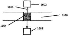
图15图示穿过多孔材料的光路的实施例。Figure 15 illustrates an embodiment of a light path through a porous material.
图16图示用于分析检测器流动池的来源和检测器构造的实施例。Figure 16 illustrates an embodiment of a source and detector configuration for an analytical detector flow cell.
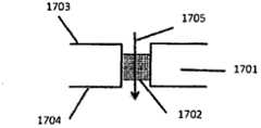
图17图示穿过多孔材料的流动方向的实施例。Figure 17 illustrates an example of flow direction through a porous material.
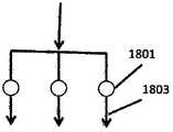
图18描述具有检测流动池的微通道的串联的、并联的和独立的微流体连接。Figure 18 depicts serial, parallel and independent microfluidic connections of microchannels with detection flow cells.
图19图示在基材和密封层内的多孔材料的截面图。Figure 19 illustrates a cross-sectional view of the porous material within the substrate and sealing layer.
图20图示在卡(card)内部的气动分布的实施例。Figure 20 illustrates an embodiment of the pneumatic distribution inside the card.
图21图示具有单通止回阀的分析卡。Figure 21 illustrates an assay card with a one-way check valve.
图22图示具有流动控制的流动控制阀的分析卡。Figure 22 illustrates an assay card with a flow control valve for flow control.
图23为阀控制通道需求的图示。Figure 23 is a graphical representation of valve control channel requirements.
图24为具有串联设置的共享五个共用存储器的检测池的测试卡。Figure 24 is a test card with detection cells arranged in series sharing five common memories.
图25为具有两组并联设置的检测池的测试卡,每组具有一个单独的存储器和四个共用的存储器。Figure 25 is a test card with two sets of detection cells arranged in parallel, each set having a separate memory and four shared memories.
图26图示具有24个检测流动池的微流体卡。Figure 26 illustrates a microfluidic card with 24 detection flow cells.
本发明的详细说明Detailed Description of the Invention
在本文中,将本发明与涉及微流体装置的特别优选的实施方式结合起来描述是方便的。然而,本发明可应用于很广泛的情况和产品中,并且应当理解为其它的构造和设置也被认为落入本发明的范围之中。对本申请中所描述的构造和设置的各种改进、替换、变形和/或添加也被认为落入本发明的领域和范围中。It is convenient herein to describe the invention in conjunction with particularly preferred embodiments relating to microfluidic devices. However, the present invention is applicable to a wide variety of situations and products, and it should be understood that other configurations and arrangements are considered to fall within the scope of the present invention. Various improvements, substitutions, variations and/or additions to the configurations and arrangements described in this application are also considered to fall within the sphere and scope of the present invention.
本发明通过提供一种选择性降低材料粘结性的方法来克服被描述为结构化层的粘结性的限制。在本发明的上下文中,将粘结性降低的材料定义为一种用于降低两个表面之间的粘结强度,或者阻止否则将已经在两个表面之间产生粘结的材料。可以在粘结过程之前或者期间施涂该粘结性降低的材料。在其最通用的形式中,本发明使用结合了印刷方法的粘结技术来改性或者覆盖具有粘结性降低的材料的表面的至少一部分,从而完全地或者部分地防止局部粘结。该结构化工艺可以在将各层粘结之前或者之后作用于所述层。The present invention overcomes the limitations described as adhesion of structured layers by providing a method of selectively reducing the adhesion of materials. In the context of the present invention, an adhesion-reducing material is defined as a material used to reduce the strength of a bond between two surfaces, or to prevent a bond that would otherwise have developed between two surfaces. The adhesion-reducing material can be applied before or during the bonding process. In its most general form, the present invention uses bonding techniques combined with printing methods to modify or cover at least a portion of a surface with a material of reduced adhesion, thereby preventing localized bonding either completely or partially. This structuring process can be applied to the layers before or after bonding the layers.
本发明具有很多用于微流体粘结的优点。首先,其提供一种简化的适于高生产能力生产的制造方法。其还通过使用已知的印刷方法能够实现对粘结工艺更大的空间控制从而提供受控的粘结区域。其还具有额外的优点,即,大量的空间和面粘结技术是可以使用的,否则因为其空间分辨率或者与微流体应用的不相容性致使其不适用。The present invention has many advantages for microfluidic bonding. First, it provides a simplified manufacturing method suitable for high throughput production. It also enables greater spatial control over the bonding process by using known printing methods to provide controlled bonding areas. It also has the added advantage that a large number of spatial and surface bonding techniques are available that would otherwise be unsuitable because of their spatial resolution or incompatibility with microfluidic applications.
粘结性降低的材料的功能在于完全地或者部分地防止粘结在空间限定区域形成和/或改进微结构内的表面特性。该粘结性降低的材料可以造成表面永久性改变,或者在粘结过程期间存在的暂时性改变。在一种实施方式中,该粘结性降低的材料包括永久性涂层。在另一种实施方式中,粘结性降低的材料包括暂时性的易挥发组分,或者在粘结过程之后可物理除去的不挥发组分。在一种实施方式中,暂时性组分的除去在装置的制造或者操作期间通过蒸发、吸收、化学反应或者机械力、气压或者液压的施加来实现。The function of the bond-reducing material is to completely or partially prevent bond formation in spatially defined areas and/or to improve the surface properties within the microstructure. This bond-reducing material can cause permanent changes to the surface, or temporary changes that exist during the bonding process. In one embodiment, the adhesion-reducing material includes a permanent coating. In another embodiment, the bond-reducing material includes a transient volatile component, or a non-volatile component that is physically removable after the bonding process. In one embodiment, removal of the transient component is accomplished by evaporation, absorption, chemical reaction, or application of mechanical, pneumatic, or hydraulic force during manufacture or operation of the device.
在一种实施方式中,该粘结性降低的材料包括一种或多种墨组分,如A)着色剂(包括颜料、调色剂和染料),其提供颜色对比;B)载色剂,或者清漆,其结合至印刷表面并且在印刷操作期间可以作为任何着色剂的载体;C)添加剂,其影响印刷适性、膜特性、干燥速度或者最终使用性能,如用于粘降低结性的化学物质组分的掺杂;D)溶剂,其可以帮助形成载色剂、降低墨的粘度、调节干燥特性、或者树脂相容性。该粘结性降低的材料可以是固体膜或者箔、粉末、高粘度糊剂、凝胶或者低粘度液体。各种干燥、固化或者附着的方法可以包括加热、氧化、UV交联、蒸发、渗透、沉淀、聚合、反应,包括辐射固化、凝胶化、冷固化或者速凝,以及热固化。In one embodiment, the adhesion-reducing material includes one or more ink components, such as A) colorants (including pigments, toners, and dyes), which provide color contrast; B) vehicle , or varnish, which binds to the printing surface and can serve as a carrier for any colorants during the printing operation; C) additives, which affect printability, film properties, drying speed or end-use properties, such as for adhesion reduction Doping of chemical components; D) solvents, which can help to form a vehicle, reduce ink viscosity, adjust drying characteristics, or resin compatibility. The adhesion reducing material may be a solid film or foil, a powder, a high viscosity paste, a gel or a low viscosity liquid. Various methods of drying, curing or attaching may include heating, oxidation, UV crosslinking, evaporation, infiltration, precipitation, polymerization, reaction, including radiation curing, gelation, cold or rapid setting, and thermal curing.
在本发明的一种优选的实施方式中,该粘结性降低的材料通过印刷技术选择性地沉积。这样的印刷技术包括但不限于:In a preferred embodiment of the invention, the adhesion-reducing material is selectively deposited by printing techniques. Such printing techniques include, but are not limited to:
·微点印刷(接触或者不接触)·Micro-dot printing (contact or non-contact)
·接触印刷·Contact printing
·丝网印刷·screen printing
·注射器或者喷墨输送· Syringe or inkjet delivery
·平版印刷· Offset printing
·干燥的或者液体化学品的机器布置· Machine layout for dry or liquid chemicals
·凸版印刷、凹版印刷、胶版或者其它这样的印刷方法Letterpress printing, gravure printing, offset printing or other such printing methods
·基于接触掩模的沉积方法· Deposition method based on contact mask
·基于激光的沉积或者表面改性技术· Laser-based deposition or surface modification techniques
·热传递方法,如利用激光、热印以及热感打印带印刷机Thermal transfer methods, such as using lasers, thermal stamps, and thermal tape printers
粘结性降低或者控制粘结的机制依赖于所使用的具体的粘结方法。这样的方法可以包括但不限于激光焊接、扩散粘结、表面改性的化学粘结、溶剂辅助粘结、热层压、化学共价或者带电的表面基团粘结、机械联锁、超声焊接、电介质粘结、微波粘结、静电或者磁力吸引、以及粘合剂粘结。在基于扩散的粘结中,该印刷的层作为全部的或者部分的阻挡层,其防止了待粘结的各层之间分子的内部扩散。类似地,在形成局部熔融的化学粘结或者机械互锁中,如利用溶剂、激光、超声、电介质、微波以及层压粘结方法,该印刷的层也可以作为阻挡层,其防止两个粘结的表面的一部分接触。替换地,该印刷的层赋予邻接表面不同的化学方面特性以改变粘结强度。The mechanism by which adhesion is reduced or controlled depends on the specific adhesion method used. Such methods may include, but are not limited to, laser welding, diffusion bonding, surface modified chemical bonding, solvent assisted bonding, thermal lamination, chemical covalent or charged surface group bonding, mechanical interlocking, ultrasonic welding , Dielectric bonding, microwave bonding, electrostatic or magnetic attraction, and adhesive bonding. In diffusion-based bonding, the printed layer acts as a full or partial barrier layer, which prevents internal diffusion of molecules between the layers to be bonded. Similarly, the printed layer can also act as a barrier layer in forming a locally fused chemical bond or mechanical interlock, such as with solvent, laser, ultrasonic, dielectric, microwave, and lamination bonding methods, which prevents the two from sticking together. A portion of the surface of the junction is in contact. Alternatively, the printed layer imparts different chemical aspects to the adjoining surfaces to vary the bond strength.
在本发明一种优选的实施方式中,至少待粘结的层之一包括聚合物,如:聚烯烃;环烯烃聚合物;聚丙烯;聚乙烯;低密度聚乙烯;高密度聚乙烯;聚甲基丙烯酸甲酯;聚碳酸酯;聚对苯二甲酸乙二酯;聚对苯二甲酸乙二酯-乙二醇共聚物;聚对苯二甲酸丁二酯;聚苯乙烯;聚酰亚胺;聚醚酰亚胺;丙烯腈-丁二烯-苯乙烯共聚物;聚氨酯;聚二甲硅氧烷;醋酸纤维素;聚酰胺;聚醚醚酮;聚氯乙烯;聚偏二氯乙烯;聚偏二氟乙烯;聚甲基戊烯;聚砜;聚四氟乙烯;聚亚甲基氧化物;硝化纤维,尼龙类,丙烯酸树脂类,醋酸酯类,聚丙烯酰胺类,胶乳或者硅石颗粒,玻璃纤维树脂类或其组合。In a preferred embodiment of the invention, at least one of the layers to be bonded comprises a polymer such as: polyolefin; cycloolefin polymer; polypropylene; polyethylene; low density polyethylene; high density polyethylene; Methyl methacrylate; polycarbonate; polyethylene terephthalate; polyethylene terephthalate-ethylene glycol copolymer; polybutylene terephthalate; polystyrene; polyimide Amine; Polyetherimide; Acrylonitrile-Butadiene-Styrene Copolymer; Polyurethane; Dimethicone; Cellulose Acetate; Polyamide; Polyetheretherketone; Polyvinyl Chloride; Polyvinylidene Chloride polyvinylidene fluoride; polymethylpentene; polysulfone; polytetrafluoroethylene; polymethylene oxide; nitrocellulose, nylons, acrylics, acetates, polyacrylamides, latex or silica Granules, fiberglass resins or combinations thereof.
在一种实施方式中,该印刷的粘结性降低的层在粘结之前仅位于一个表面上。例如,在图1a)和b)中,如粘结之前的图1a)和粘结之后的图1b)所示,该粘结性降低的层103在粘结至表面102上之前仅位于一个表面101上。在替换的实施方式中,该印刷的层可以位于两个邻接的表面上。例如图1c)和d),如粘结之前的图1c)和粘结之后的图1d)所示,粘结性降低的层103位于表面101和102上。In one embodiment, the printed bond-reducing layer is on only one surface prior to bonding. For example, in Figures 1 a) and b), the reduced
在本发明的另一种实施方式中,该印刷的粘结性降低的层位于邻近的表面上,但是没有与粘结区域直接接触,并且作用为在粘结表面的区域内减少粘性工艺。例如,在激光焊接中,该印刷的层可以作为掩膜,其部分地或者完全地有效防护目标区域避开激光束。图2示出通过激光辐射粘结的两个层。印刷的层204可以或者不可以直接与受粘结工艺影响的位于层201和202界面的表面接触。该印刷的层部分地或者完全地反射、吸收、或者扩散激光能量,其导致由该印刷的层所覆盖的界面处的粘结降低。In another embodiment of the invention, the printed adhesion-reducing layer is located on the adjacent surface, but is not in direct contact with the bonding area, and acts as an adhesion-reducing process in the area of the bonding surface. For example, in laser welding, the printed layer can act as a mask, which partially or completely effectively shields the target area from the laser beam. Figure 2 shows two layers bonded by laser radiation. The printed layer 204 may or may not be in direct contact with the surface affected by the bonding process at the interface of layers 201 and 202 . The printed layer partially or completely reflects, absorbs, or diffuses laser energy, which results in reduced adhesion at the interface covered by the printed layer.
在本发明的另一种实施方式中,该粘结性降低的材料可以赋予或者改变表面的静电或者磁性状况从而引起粘结强度的变化。In another embodiment of the invention, the bond-reducing material may impart or alter the electrostatic or magnetic state of the surface to cause a change in bond strength.
在一种实施方式中,该粘结性降低的材料改变了表面的静电特性从而引起粘结强度的变化。图3描述了层301、302相互接触的相邻表面,其带有相反的电荷并且贡献于粘结强度,除了在其中印刷的层303提供了贡献排斥力的电荷并由此在该区域内降低了粘结强度。静电力(F)的大小可以通过库伦定律来计算,其中施加在电荷(q1)上的力由于第二电荷(q2)的存在而产生,该静电力(F)由下式In one embodiment, the bond-reducing material alters the electrostatic properties of the surface causing a change in bond strength. Figure 3 depicts adjacent surfaces where
得到,其中r为两个电荷之间的距离,并且ke为比例常数,其约等于9×10⁹Nm2/C2。正值的力表示相互排斥,而负值力表示相互吸引。, where r is the distance between the two charges and keis a constant of proportionality approximately equal to 9×10⁹ Nm2 /C2 . A positive force indicates mutual repulsion, while a negative force indicates mutual attraction.
在另一种实施方式中,该粘结性降低的材料包括磁性、铁磁性或者顺磁性的特性,其可以有效地用于引起粘结强度的变化。在图4A和4B中示出不具有和具有外加磁场404的实施例。其中,存在具有磁性或者顺磁性特性材料的印刷层403,其在层401和402之间界面连接。能够施加在涂覆表面的机械力可以根据下述方程式增大或者减小。In another embodiment, the bond-reducing material includes magnetic, ferromagnetic, or paramagnetic properties that can be effectively used to induce a change in bond strength. Embodiments without and with an applied
其中A为每个表面的面积,以m2计;H为其磁场,以A/m计;μ0为空间的导磁率,其等于4π×10-7T·m/A;并且B为通量密度,以T计。where A is the area of each surface in m2 ; H is its magnetic field in A/m; μ0 is the magnetic permeability of space, which is equal to 4π×10−7 T·m/A; and B is the flux Quantity density, in T.
该粘结性降低的材料可以延伸超过粘结表面的界面。在本发明的另一种实施方式中,该印刷沉积的粘结性降低的材料延伸超过两个表面之间的粘结区域从而在涂覆表面和微流体结构之间提供界面涂层。这是特别有利的,因为该粘合剂层否则将提供在微结构表面中的一个并导致在微流体应用中不利的表面特性。如此获得的优点可以包括改变表面毒性、可润湿性、非特异性的结合、拓扑结构、透明度或者折射率性能。图5a和5b分别示出主视图和截面图,利用503指出图5b的截面图来自图5a的位置。所示的平行微通道504含有粘结性降低的材料501,其被印刷在微通道504的上表面和下表面,而不是固体表面502之间。The bond-reducing material may extend beyond the interface of the bonding surfaces. In another embodiment of the invention, the print-deposited adhesion-reducing material extends beyond the bonded area between the two surfaces to provide an interfacial coating between the coated surface and the microfluidic structure. This is particularly advantageous since the adhesive layer would otherwise provide one of the microstructured surfaces and lead to unfavorable surface properties in microfluidic applications. Advantages so obtained may include changes in surface toxicity, wettability, non-specific binding, topology, transparency or refractive index properties. Figures 5a and 5b show a front view and a cross-sectional view, respectively, with 503 indicating that the cross-sectional view of Figure 5b is from the location of Figure 5a.
本发明对于面粘结方法是特别有利的,如扩散、表面改性、溶剂以及热层压,从而避免相邻的层在微结构内部以及其附近的粘结。类似地,选择性粘结技术的分辨率可以通过使用这样的印刷层来改进。正下方的表格描述了大致的分辨率以及由当前的卷盘到卷盘的印刷方法可获得的印刷材料的厚度。The present invention is particularly advantageous for surface bonding methods such as diffusion, surface modification, solvent and thermal lamination to avoid bonding of adjacent layers within and adjacent to the microstructure. Similarly, the resolution of selective bonding techniques can be improved through the use of such printed layers. The table directly below describes the approximate resolution and thickness of printed material achievable with current reel-to-reel printing methods.
表:卷盘到卷盘的印刷技术的分辨率Table: Resolution of Reel-to-Reel Printing Technologies

在制造过程中微结构可能产生变形的情况下,粘结性降低的材料可以用来防止粘合,并且由此防止微结构的永久变形。例如,如果在通道宽度大于通道高度的情况下使粘结过程中不发生变形,利用聚合物层(片、膜或者层压制品)密封微通道或者室结构通常是有问题的。这样的有问题的粘结工艺包括通过辊夹持的热扩散和层压。当通道的宽度和压力足够大时,基本上会发生变形并且该微通道相对的表面可能发生接触。如果微结构的上表面和下表面发生接触,可以通过在这些结构的顶部和/或底部涂覆(图5中示出的实施例)来防止形成永久性粘结。Where deformation of the microstructure may occur during fabrication, a bond-reducing material may be used to prevent adhesion, and thus permanent deformation of the microstructure. For example, sealing microchannel or chamber structures with polymer layers (sheets, films or laminates) is often problematic if the channel width is greater than the channel height so that deformation does not occur during bonding. Such problematic bonding processes include thermal diffusion and lamination by roller nip. When the width of the channel and the pressure are large enough, deformation will substantially occur and the opposing surfaces of the microchannel may come into contact. If the upper and lower surfaces of the microstructures come into contact, permanent bonds can be prevented from forming by coating the top and/or bottom of these structures (example shown in Figure 5).
在一种实施方式中,该粘结性降低的层提供邻接于粘结边缘的微流体通道的轮廓。图6a和6b分别表示印刷层601勾画出的沿着基材603的粘结边缘的通道结构602的主视图和侧视图。其对于改善标准粘结技术的公差以确保微通道的化学和结构的完整性是尤其有用的。In one embodiment, the adhesion-reducing layer provides the contours of the microfluidic channel adjacent to the bonded edges. Figures 6a and 6b show a front view and a side view, respectively, of a
在另一种实施方式中,压力泄压或者爆破阀包含粘结性降低的材料。图7a示出由壁部件702隔离的通道701的正视图,该壁部件702具有印刷来避免壁部件702的粘结的粘结性降低的材料703。图7b示出当阀闭合并且可变形层704与具有印刷层703的壁结构702接触时的侧视图。图7c图示在施加力705下该结构所发生的情况,其使得顶部和底部的可变形层704能够变形成凹槽706。In another embodiment, the pressure relief or burst valve comprises a bond-reducing material. FIG. 7 a shows a front view of a
图8a,8b和8c图示使用一个可变形层的压力泄压阀或者爆破阀。图8a图示由壁部件802隔离的通道801的主视图,该壁部件802具有印刷来避免壁部件802的粘结的粘结性降低的材料803。图8b图示该阀闭合并且可变形层804与具有印刷层803的壁结构802相接触的侧视图。图8c图示当该阀通过向室805内施加压力807被开启时,由此使能够通过气压或者液压驱动可变流体控制阀与微流体通道801分离。图8c图示如何将负压力807施加至变形层804之上的室805,从而帮助变形层804移动离开壁结构802,由此能够使流体流806穿过微流体通道801。类似地,可以施加正压来帮助确保该阀闭合或者提供限制性压力来控制通道内流体的流动速率。Figures 8a, 8b and 8c illustrate a pressure relief valve or burst valve using a deformable layer. FIG. 8 a illustrates a front view of a
在本发明的另一种实施方式中,用于存储和释放试剂的爆破阀包括粘结性降低的材料。这有效地使在微结构中、在空间上预限定的点处形成密封,该密封可以一直保持直至使用作用力在这些预限定的点处克服该降低的粘结强度。本发明能够实现对氧气和水传输有效的阻挡层,直至爆破阀被开启,其对于长时间的储存和释放试剂是十分关键的。In another embodiment of the invention, a burst valve for storing and releasing reagents includes a bond-reducing material. This effectively creates a seal at spatially predefined points in the microstructure that can be maintained until the reduced bond strength is overcome at these predefined points using applied force. The present invention enables an effective barrier to oxygen and water transport until the burst valve is opened, which is critical for long-term storage and release of reagents.
在另一种实施方式中,阀结构包括粘结性降低的材料。图9图示在止回阀或者单通阀中使用的粘结性降低的材料901。图9a示出正视图并且图9b和9c分别示出阀闭合和开启时的侧视图。该粘结性降低的材料901确保变形层902没有被粘结至阀结构附近的基材906。当微通道903和904之间的正压差足够大时,变形层902变形进入通道904内并且流体905可以从通道903流至通道904。如果在通道904至903之间反方向存在明显的压力,然后按压可变形层902使其抵住基材906从而防止流体在该方向上流动。In another embodiment, the valve structure includes a bond-reducing material. Figure 9 illustrates an
止回阀或者单通阀的替换的实施方式分别在图10和图11中示出。图10示出具有通孔1003的基材结构1004的主视图,该通孔1003在具有开口1002的可变形层上被印刷的粘结性降低的材料1001覆盖。图11a和11b分别图示相同的阀结构处于闭合和开启时的侧视图。变形层1101包含在阀附近印刷在其表面上的粘结性降低的材料从而确保可变形层1101在阀结构的附近没有被粘结至基材1105,并且当阀开启时穿过可变形层1101的切口1102能够使流体通过。当微通道1103和1104之间的正压差使得可变形层1101变形进入通道1104中时,流体可以如箭头1106和1107所示通过切口1102从通道1103流向通道1104。如果在通道1104至1103之间、在反方向上存在明显的压力,那么按压可变形层1101使其抵住基材1106从而防止流体在该方向上的流动。Alternative embodiments of check valves or one-way valves are shown in FIGS. 10 and 11 , respectively. FIG. 10 shows a front view of a
在本发明的另一方面,形成包含泵和/或阀组件的复合流体处理系统是十分有利的。在本发明的一种实施方式中,微流体泵结构包含粘结性降低的材料。图12和13分别图示使用粘结性降低的材料的注射器泵和蠕动式泵的实施例。图12a图示在共用的泵室1209中施加负压力1201,其通过提升印刷的粘结性降低的层1203附近的可变形层1202来开启入口阀,从而能够使流体从通道1206流进室1209。类似地,图12b图示在共用的泵室1209施加正压力1208,其通过下压在印刷层1204附近的1205来迫使流体流出出口阀,从而能够使流体通过通道1207流出。In another aspect of the present invention, it is highly advantageous to form a composite fluid treatment system that includes pump and/or valve assemblies. In one embodiment of the invention, the microfluidic pump structure comprises a bond-reducing material. 12 and 13 illustrate embodiments of syringe pumps and peristaltic pumps, respectively, using adhesion-reducing materials. Figure 12a illustrates the application of
在另一种实施方式中,图13a示出与图8类型相似的被设置为依次连接微通道1302,1303,1304和1305的三个阀1301的主视图。通过按顺序操作这些阀中的每一个,可以获得蠕动式移动的流体,如在图13b,c和d中所示的。图13b图示当施加负压驱动力1306从而开启第一阀并且施加正压驱动力1308、1309至随后的阀从而保持其闭合时的截面图。然后,流体流动1307可以发生在通道1302和1303之间。图13c图示下一个状态的截面图,其中施加负压驱动力1308、1309以开启第二阀和第三阀然后施加正压驱动力1306以闭合第一阀。来自于第一阀的闭合所迫使的流体的流动1307然后可发生在通道1303和1304之间,并且接下来流体从1304转移到1305。类似地,图13d图示下一个状态的截面图,其中第二阀通过力1308闭合,同时第一阀通过1306保持闭合并且第三阀通过1309开启,从而驱使流体1307从室1304流到1305。然后重复该循环以使泵运转继续。In another embodiment, Fig. 13a shows a front view of three
在本发明的另一方面,将该粘结性降低的材料用来防止粘结至微流体装置内的整合的部件的一部分。当应用于微流体装置结构和整合的部件的材料均与粘结工艺相匹配时,其是尤其重要的。例如,图14示出包含整合的过滤器或者多孔聚烯烃组件1401的聚烯烃微流体装置1400的一部分的截面。将粘结性降低的材料1402涂覆在过滤器的不需要粘结的部分的上部和下部,由此能够在两个通道之间通过过滤器的该部分而使流体连通。In another aspect of the invention, the adhesion-reducing material is used to prevent adhesion to a portion of an integrated component within a microfluidic device. This is especially important when both the materials used in the microfluidic device structure and the integrated components are compatible with the bonding process. For example, FIG. 14 shows a cross-section of a portion of a
在本发明的另一种实施方式中,微流体装置包括泵和/或阀组件的任意组合,其中使用粘结性降低的材料。In another embodiment of the present invention, the microfluidic device comprises any combination of pump and/or valve components, wherein a bond-reducing material is used.
本发明通过提供一种具有包含多孔材料的离散光学检测流动池并且具有用于流体传输和/或除去的连接的微通道的平面基材以及用于制备该基材的方法来克服被描述为亲和色谱的应用中的限制。The present invention overcomes the problems described as hydrophilic by providing a planar substrate having a discrete optical detection flow cell comprising a porous material and having connected microchannels for fluid transport and/or removal and a method for making the substrate. and limitations in chromatographic applications.
本发明使用被插入进平面基材中的多孔材料,其中去向或者来自于多孔介质的流动能够通过至少一个连接的微通道而实现,并且其具有用于分析多孔网络中的分析物的光学检测手段。The present invention uses a porous material inserted into a planar substrate, where flow to or from the porous medium can be achieved through at least one connected microchannel, and which has optical detection means for analyzing analytes in the porous network .
本发明具有多个优点。这些优点包括:The present invention has several advantages. These advantages include:
·涉及表面结合性的分析的分析敏感度的增加,这是由于在多孔结构中可利用的表面积大于用于基于传统的微流体和孔板(well plate)的分析方法的表面积。• Increased analytical sensitivity of assays involving surface binding, due to the fact that the surface area available in porous structures is greater than that used for traditional microfluidic and well plate based analytical methods.
·更快的涉及表面基团的分析反应的反应动力学,这是由于通过多孔网络的试剂流使分析物与表面基团更加接近。• Faster reaction kinetics of analytical reactions involving surface groups due to the closer proximity of the analyte to the surface groups due to the flow of reagents through the porous network.
·降低光学检测位点之间的干扰的离散检测流动池,这是由于其被插入到基材中。• Discrete detection flow cells that reduce interference between optical detection sites due to their insertion into the substrate.
·对于平行结构改进的流动特性,这是由于多孔结构提供的反压,从而确保流动分布受到控制。• Improved flow characteristics for parallel structures due to the back pressure provided by the porous structure ensuring a controlled flow distribution.
·在插入至基材中之前通过间歇法提供离线(offline)多孔网络制备的能力。• Provides the ability for offline porous network preparation by a batch process prior to insertion into a substrate.
本发明能够简化待使用的制造方法并降低其成本,否则需要具有更小公差的更小的结构来提供等同的微结构流动池。具有很多可商用的购自很多供应商的比色的、吸收的、荧光的和化学发光的化合物,其可用于本发明的光学检测。该多孔的光学流动池可以以高敏感度、使用不透明的或者透明的多孔材料操作。可以将穿过多孔网络的光学光路描述为图15中所示的两种情况的变形。图15a)图示本发明光学检测池的一部分的实施例,其中光线1502通过多孔网络1501的孔1503穿过,同时图15b)图示光路1504通过透明的多孔材料1505穿过的实施例。The invention enables to simplify and reduce the cost of the manufacturing method to be used, which would otherwise require smaller structures with tighter tolerances to provide an equivalent microstructured flow cell. There are a number of colorimetric, absorbing, fluorescent and chemiluminescent compounds commercially available from a number of suppliers that can be used in the optical detection of the present invention. The porous optical flow cell can be operated with high sensitivity, using opaque or transparent porous materials. The optical light path through the porous network can be described as a variation of the two cases shown in FIG. 15 . Figure 15a) illustrates an embodiment of a part of an optical detection cell according to the present invention, wherein
可以将该流动池构建为具有任选的光源或者检测光学器件,其位于所述检测流动池的相对侧或者同一侧。在使用化学发光的或者其它种发光的分析的情况中不需要光源体系。在一种实施方式中,该光源和检测系统位于所述平面基材的任一侧。例如,图16a示出光路1601从光源系统1602穿过在基材1605中包含多孔材料1604的检测流动池到达检测器系统1603。在一种替换的实施方式中,该光源和检测器系统位于所述基材的同一侧。例如,图16b)描述来自于光源系统1602的光1601穿过在基材1602中包含多孔材料1604的检测流动池,并通过多孔材料1604和/或反射层1606的组合被反射至检测器系统1603。The flow cell can be constructed with optional light source or detection optics located on the opposite side or on the same side as the detection flow cell. In the case of assays using chemiluminescent or other types of luminescence no light source system is required. In one embodiment, the light source and detection system are located on either side of the planar substrate. For example, FIG. 16 a shows an
在一种优选的实施方式中,将该多孔材料设置为使穿过多孔结构的流动垂直于基材表面。图17描述具有包含多孔材料1702的检测流动池的基材1701的截面,流体穿过检测池1702的流动方向通过箭头1705指示,其垂直于基材表面1703、1704。In a preferred embodiment, the porous material is arranged such that the flow through the porous structure is perpendicular to the surface of the substrate. FIG. 17 depicts a cross-section of a
在本发明的一种优选的实施方式中,一种基材可以具有多个包含多孔材料的检测流动池。需要多个试剂检测的分析实例包括但不限于多个试样的读取,在相同试样中多个分析物的读取,对照试样的使用,校准因数以及分析重复或者重复相同的测试。可以将该多个检测流动池1801以串联的构型1802或者以并联的构型1803设置为具有相互连接的微通道,或者将其设置为具有相互之间独立流动的微通道1804,分别如在图18a),18b),和18c)中所示。该微通道的构型基于分析、界面连接的仪器设备以及使用者需求来建造。可以将实施例的装置制备为床旁检测或者实验室应用,其实施范围可以从具有邮票尺寸的小型测试卡到工业标准版式,例如显微镜载物片或者微量滴定板。In a preferred embodiment of the invention, a substrate can have a plurality of detection flow cells comprising porous material. Examples of assays requiring multiple reagent detection include, but are not limited to, multiple sample reads, multiple analyte reads in the same sample, use of control samples, calibration factors, and assay replicates or repetitions of the same test. The plurality of
在本发明一个优选的方面,提供一种用于改进光学检测的装置,其通过在检测流动池内引入多孔材料从而增加用于结合的表面积。其中的一个实施例为将多孔材料用作在亲和色谱中结合分析物的固定相。在一种实施方式中,该多孔材料可以是聚合物、玻璃或者陶瓷过滤器,其可以是或不是表面改性的以提供用于结合的可控的表面化学。这样的聚合物可以包括但不限于环烯烃聚合物;聚丙烯;聚乙烯;低密度聚乙烯;高密度聚乙烯;聚甲基丙烯酸甲酯;聚碳酸酯;聚对苯二甲酸乙二酯;聚对苯二甲酸乙二酯-乙二醇共聚物;聚对苯二甲酸丁二酯;聚苯乙烯;聚酰亚胺;聚醚酰亚胺;丙烯腈-丁二烯-苯乙烯共聚物;聚氨酯;聚二甲硅氧烷;醋酸纤维素;聚酰胺;聚醚醚酮;聚氯乙烯;聚偏二氯乙烯;聚偏二氟乙烯;聚甲基戊烯;聚砜;聚四氟乙烯;聚亚甲基氧化物;硝化纤维,尼龙类,丙烯酸树脂类,醋酸酯类,聚丙烯酰胺类,胶乳或者硅石颗粒,玻璃纤维类或其组合。In a preferred aspect of the present invention there is provided a device for improving optical detection by introducing a porous material within the detection flow cell to increase the surface area for binding. One example of this is the use of porous materials as stationary phases for binding analytes in affinity chromatography. In one embodiment, the porous material may be a polymer, glass or ceramic filter, which may or may not be surface modified to provide a controlled surface chemistry for binding. Such polymers may include, but are not limited to, cycloolefin polymers; polypropylene; polyethylene; low density polyethylene; high density polyethylene; polymethyl methacrylate; polycarbonate; polyethylene terephthalate; Polyethylene terephthalate-ethylene glycol copolymer; Polybutylene terephthalate; Polystyrene; Polyimide; Polyetherimide; Acrylonitrile-butadiene-styrene copolymer Polyurethane; Polydimethylsiloxane; Cellulose acetate; Polyamide; Polyether ether ketone; Polyvinyl chloride; Polyvinylidene chloride; Polyvinylidene fluoride; Polymethylpentene; Polysulfone; Polytetrafluoroethylene Ethylene; polymethylene oxide; nitrocellulose, nylons, acrylics, acetates, polyacrylamides, latex or silica particles, glass fibers or combinations thereof.
在一种实施方式中,表面化学的改变或者表面涂层与多孔材料的结合可以在将其插入至卡内之前通过基于间歇式的工艺来实现。在一种替换的实施方式中,表面化学的改变或者表面涂层与多孔材料的结合可以在将卡制成之后通过使用如在本申请中所述的流通的实验方案进行。In one embodiment, the modification of the surface chemistry or the bonding of the surface coating to the porous material may be accomplished by a batch-based process prior to its insertion into the card. In an alternative embodiment, the modification of the surface chemistry or the bonding of the surface coating to the porous material can be performed after the card has been fabricated using a flow-through protocol as described in this application.
在一种实施方式中,使用表面活化步骤来活化所述多孔材料的表面。表面活化涉及改变存在于表面上的化学基团,并且其结果依赖于基材以及活化方法。通常的化学粘结改性的实例包括胺、羧酸以及羟基类。用于表面改性的工业标准方法包括电晕放电、湿法化学改性、使用各种气体的等离子体,如氩气、氧气、氮气、环氧乙烷、氨、丙酮、甲醇以及乙二胺。In one embodiment, a surface activation step is used to activate the surface of the porous material. Surface activation involves changing the chemical groups present on the surface, and the results are dependent on the substrate as well as the activation method. Examples of common chemical bonding modifications include amines, carboxylic acids, and hydroxyls. Industry standard methods for surface modification include corona discharge, wet chemical modification, plasma using various gases such as argon, oxygen, nitrogen, ethylene oxide, ammonia, acetone, methanol, and ethylenediamine .
在一种实施方式中,在多孔材料上的表面涂覆为多层涂覆。该层的附着可以是共价键、静电或者由物理包容而导致的并且对生物化学和表面处理领域技术人员是熟知的。这样的层的实例包括当附着至基材或者另一个涂层时整体或者局部带有电荷(阳离子或者阴离子)的或者是能够提供这些电荷的材料、小分子例如盐、生物分子、中性或者带电的聚合物或者聚合电解质、配体、表面活性剂及其组合。多种类型的聚合物经常用于直接粘合至表面。In one embodiment, the surface coating on the porous material is a multilayer coating. Attachment of this layer can be covalent, electrostatic or by physical containment and is well known to those skilled in the art of biochemistry and surface treatment. Examples of such layers include materials, small molecules such as salts, biomolecules, neutral or charged, which are wholly or partially charged (cationic or anionic) or are capable of imparting these charges when attached to a substrate or another coating. polymers or polyelectrolytes, ligands, surfactants, and combinations thereof. Various types of polymers are often used for direct bonding to surfaces.
在一种实施方式中,一种或多种表面涂层可以包括如下的任何物质:表面活性剂,阳离子表面活性剂类、阴离子表面活性剂类、两性表面活性剂类、以及含氟表面活性剂类、磷酸盐、聚乙烯亚胺(PEI)、聚乙烯基咪唑啉、季铵化聚丙烯酰胺、聚乙烯基吡啶、聚乙烯吡咯基烷酮、聚乙烯基胺类、聚烯丙基胺类、脱乙酰壳多糖、聚赖氨酸、聚丙烯酸酯三烷基氨盐酯(poly(acrylate trialkylammonia salt ester))、纤维素、聚丙烯酸(PAA)、聚甲基丙烯酸、聚苯乙烯磺酸、聚乙烯基磺酸、聚甲苯磺酸、甲基乙烯基醚-马来酸共聚物、聚谷氨酸、葡聚糖硫酸酯、透明质酸、肝素、藻酸、己二酸、化学染料、蛋白质、酶、蛋白质类、酶类、脂类、激素类、肽类、核酸类、寡核苷酸类、DNA、RNA、糖类和多糖类、免疫球蛋白G类(IgG类)和白蛋白类,如牛血清白蛋白(BSA)和人血清清蛋白、肽、异氰酸酯封端的聚合物类,其包括聚氨酯、以及聚乙二醇(PEG)、环氧基封端的聚合物类,其包括PEG和聚硅氧烷类、以及羟基琥珀酰亚胺封端的聚合物类或其盐或酯。In one embodiment, the one or more surface coatings may include any of the following: surfactants, cationic surfactants, anionic surfactants, amphoteric surfactants, and fluorosurfactants Classes, phosphates, polyethyleneimine (PEI), polyvinylimidazoline, quaternized polyacrylamide, polyvinylpyridine, polyvinylpyrrolidone, polyvinylamines, polyallylamines , chitosan, polylysine, poly(acrylate trialkylammonia salt ester) (poly(acrylate trialkylammonia salt ester)), cellulose, polyacrylic acid (PAA), polymethacrylic acid, polystyrene sulfonic acid, Polyvinylsulfonic acid, polytoluenesulfonic acid, methyl vinyl ether-maleic acid copolymer, polyglutamic acid, dextran sulfate, hyaluronic acid, heparin, alginic acid, adipic acid, chemical dyes, Proteins, enzymes, proteins, enzymes, lipids, hormones, peptides, nucleic acids, oligonucleotides, DNA, RNA, sugars and polysaccharides, immunoglobulin G (IgG) and white Proteins, such as bovine serum albumin (BSA) and human serum albumin, peptides, isocyanate-terminated polymers including polyurethanes, and polyethylene glycol (PEG), epoxy-terminated polymers including PEGs and polysiloxanes, and hydroxysuccinimide terminated polymers or salts or esters thereof.
在一种实施方式中,可以将生物素或者PEG的层涂覆在多孔材料上,其中该多孔材料具有带电表面,其所带电荷与PEG或者生物素分子的官能团相反。在另一种实施方式中,生物分子,例如蛋白质、酶、肽、DNA或者RNA的层静电吸附在多孔材料的表面。In one embodiment, a layer of biotin or PEG can be coated on a porous material, wherein the porous material has a charged surface opposite to the functional group of the PEG or biotin molecule. In another embodiment, a layer of biomolecules, such as proteins, enzymes, peptides, DNA or RNA, is electrostatically adsorbed to the surface of the porous material.
在卡组装的过程中,将多孔材料插入至基材内。可以将在过滤器的界面处与周围材料的粘合或者局部熔合用来沿着过滤器的边缘形成密封。在一种优选的实施方式中,将压力装配件用来将过滤器压进直径比该过滤器小的孔内。该压进装配件要求没有粘合性并且确保在过滤器材料边缘的周围没有流体泄露。During card assembly, the porous material is inserted into the substrate. Bonding or localized fusing with surrounding material at the interface of the filter may be used to form a seal along the edge of the filter. In a preferred embodiment, a pressure fitting is used to press the filter into a hole of smaller diameter than the filter. The press fit requires no adhesion and ensures no fluid leakage around the edge of the filter material.
该基材可以由任意合适的聚合物制得,如:聚烯烃;环烯烃聚合物;聚丙烯;聚乙烯;低密度聚乙烯;高密度聚乙烯;聚甲基丙烯酸甲酯;聚碳酸酯;聚对苯二甲酸乙二酯;聚对苯二甲酸乙二酯-乙二醇共聚物;聚对苯二甲酸丁二酯;聚苯乙烯;聚酰亚胺;聚醚酰亚胺;丙烯腈-丁二烯-苯乙烯共聚物;聚氨酯;聚二甲硅氧烷;醋酸纤维素;聚酰胺;聚醚醚酮;聚氯乙烯;聚偏二氯乙烯;聚偏二氟乙烯;聚甲基戊烯;聚砜;聚四氟乙烯;聚亚甲基氧化物;硝化纤维,尼龙类,丙烯酸树脂类,醋酸酯类,聚丙烯酰胺类,胶乳或者硅石颗粒,玻璃纤维类或其组合。The substrate can be made of any suitable polymer, such as: polyolefin; cycloolefin polymer; polypropylene; polyethylene; low density polyethylene; high density polyethylene; polymethyl methacrylate; polycarbonate; Polyethylene terephthalate; Polyethylene terephthalate-ethylene glycol copolymer; Polybutylene terephthalate; Polystyrene; Polyimide; Polyetherimide; Acrylonitrile - Butadiene-styrene copolymer; polyurethane; polydimethylsiloxane; cellulose acetate; polyamide; polyether ether ketone; polyvinyl chloride; polyvinylidene chloride; polyvinylidene fluoride; polymethyl Pentene; polysulfone; polytetrafluoroethylene; polymethylene oxide; nitrocellulose, nylons, acrylics, acetates, polyacrylamides, latex or silica particles, glass fibers or combinations thereof.
微流体通道可以形成在基材内,或者形成在连接至该基材的附着层内。图19a)描述了薄的层压密封层1902、1903和具有多孔材料1904的基材1901在组装之前的截面。在某些实施方式中,可以将该薄的层压层1902、1903用来与基材1901形成密封。在一种实施方式中,该装置具有包含微流体结构的多层层压组合物。例如,该薄的密封层1902、1903可以由多层层压材料形成,其包含如在WO 2007/085043中所描述的微通道,其全部内容被以引用的方式并入本文。Microfluidic channels can be formed in the substrate, or in an adhesive layer attached to the substrate. Figure 19a) depicts a cross section of thin
图19b)描述了密封层1905、1906和具有多孔材料1904的基材1901在组装之前的截面。在某些实施方式中,基材1901或者密封层1905、1906包含微通道,其可以通过如下的方法形成,该方法包括但不限于:微碾磨、基于激光的平版印刷和电子束扫描、等离子体蚀刻、使用光致抗蚀剂的湿法化学UV平版印刷、软性平版印刷、X射线平版印刷、印刷头沉积、软性平版印刷、冲压、模压、压模、热成型、注射模塑以及反应注射模塑。Figure 19b) depicts a cross-section of the sealing
对于很多微流体应用,在这些微流体装置中控制泵送、调阀或者消泡是有利的。执行这些操作的组件构造的实例在WO 2007/060523中有所描述,其全部内容被以引用的方式并入本文。图20描述一个实施例的实施,其中可以向卡上的共用的端口2002施加气动驱动力2001,并且之后通过卡内的气动微通道2003分布至入口或者阀的位置2004。For many microfluidic applications, it is advantageous to control pumping, valve regulation, or defoaming in these microfluidic devices. An example of a component configuration to perform these operations is described in WO 2007/060523, the entire contents of which are incorporated herein by reference. Figure 20 depicts the implementation of an embodiment where a
在本发明的一种实施方式中,装置包括多个具有单通阀的入口微通道,和/或消泡器,和/或至少一个检测流动池,其中任选地,由装置外部单独受控的流体管线提供微流体流动的控制。例如,图21的装置描述装置2100,其包含五个具有单通止回阀2102的入口通道2101,其被连接至消泡器2103,接下来是检测池2204,然后是共用的出口2106。对每个通道2101的压力2105都是变化的,从而在每个单独的通道中控制流动和由此控制输送至检测池2104的流体的时间和体积。将单通止回阀2102用来阻止流体从一个入口通道向另一个入口通道的回流。In one embodiment of the invention, the device comprises a plurality of inlet microchannels with one-way valves, and/or defoamers, and/or at least one detection flow cell, which optionally is individually controlled externally from the device The fluidic lines provide control of the microfluidic flow. For example, the device of FIG. 21 depicts a
使用流动控制阀的方法通过对阀进行控制来调节来自于单一来源的流动速率,其对于通过减少复合装置所需要的泵和阀组件的数量来缩减外部器件的成本和尺寸的是特别有利的。The method of using a flow control valve to regulate the flow rate from a single source by controlling the valve is particularly advantageous for reducing the cost and size of external components by reducing the number of pump and valve assemblies required for the compound device.
在本发明的一种实施方式中,该装置包括多个具有可变的流动阀的入口微通道,和/或消泡器,和/或至少一个检测流动池,其中任选地,装置外部的压力源提供压力驱动的流动,该流动通过流动控制阀而改变。例如,图22描述具有施加于穿过入口的一些或者全部流体的共用压力源2205的装置2200,其中该流动在各个通道2201内受到活性流动控制阀2202(其类似于在图8中所示的那些)的外部驱动的控制,以此来调节在每个通道中的流动。在这一实施例中,流动控制阀2202的外部气动控制将提供来自于在2205处的正压力或者施加在共用的出口2206的负压力的流动控制。消泡器2203防止气泡穿过并到达检测池2204。In one embodiment of the invention, the device comprises a plurality of inlet microchannels with variable flow valves, and/or defoamers, and/or at least one detection flow cell, wherein optionally, external A pressure source provides a pressure-driven flow that is varied by a flow control valve. For example, FIG. 22 depicts a
在本发明的一种实施方式中,该装置包括内置试剂,和/或具有可变的流动阀的微通道,和/或消泡器,和/或至少一个检测流动池,其中任选地,装置外部的压力源提供压力驱动的流动,该流动通过流动控制阀而变化。例如,图23示出六个具有四个气动线路2302的流体通道2301通过每条线路使用多个阀2303进行的气动驱动。在这种方式中,可以分别控制每个通道2301,因为每个通道2301具有用于流动控制的两个阀2303。这确保了当一个通道2301在使用中时,每个其它的通道2301具有至少一个气动线路2302,该气动线路2302与激活的通道的控制线路相分离以独立地控制流动。在每个线路中使用更多的阀2303将进一步增加可单独控制的流体通道2301的数量。类似地,更多的气动线路2302极大的增加了阀2303的组合并且由此极大地增加了独立受控的流体通道2301的数量。例如,六个气动端口将允许15个可独立控制的通道2301,每个通道仅使用两个阀2303。In one embodiment of the present invention, the device includes built-in reagents, and/or microchannels with variable flow valves, and/or defoamers, and/or at least one detection flow cell, wherein optionally, A pressure source external to the unit provides a pressure-driven flow that is varied by a flow control valve. For example, FIG. 23 shows the pneumatic actuation of six
在另一种实施例中,微流体卡包括用于试剂储存,和/或混合或者再水合,和/或消泡器,和/或控制剂量,和/或流动控制和被动阀,和/或至少一个包含多孔材料的检测流动池的组件。可以将这些流动处理组件再次构建在不同的卡上以满足不同的分析需要。这样的分析包括但不限于:免疫分析,如间接的、夹层的、竞争的以及反ELISA方法。在图24的实施例中,装置2400将可控剂量的试样通过试样室2403的注射器式泵2404注射入试样混合室2403(通过试样过滤器2406抽取一部分试样)中。该试样混合室还可以包含试剂,例如细胞溶解材料,其用于与试样混合。当水在作用力2411下从水室2408泵出时,该试剂将再水合并将试样混合。随着与流动控制阀2402结合的消泡器在试剂室2401处闭合,水将进入腔室取代穿过消泡器孔口2402的空气,直至将所有的室2401填充。然后可以单独控制该再水合的和混合的试剂以流过检测池2412并流出到具有排放结构2410的废料储室2409。可以通过装置2400上的光学检测器件和/或使用外部器件分析检测池2412。In another embodiment, the microfluidic card includes components for reagent storage, and/or mixing or rehydration, and/or defoamers, and/or dose control, and/or flow control and passive valves, and/or At least one component of the detection flow cell comprising a porous material. These flow processing components can again be built on different cards to meet different analytical needs. Such assays include, but are not limited to, immunoassays such as indirect, sandwich, competition and reverse ELISA methods. In the embodiment of FIG. 24, the device 2400 injects a controlled dose of sample into the
试剂的存储可以是液体的或者干燥的形式。在一种实施方式中,将干燥的冻干试剂置于试剂和重组室(reconstitution chamber)中,并且通过水室存储或者加入水。Storage of reagents can be in liquid or dry form. In one embodiment, the dried lyophilized reagent is placed in a reagent and reconstitution chamber and water is stored or added via the water chamber.
出于存放寿命和稳定性的考虑,在诊断应用中提供的干燥形式的试剂通常是有利的。干燥的试剂以及冻干的方法是本领域技术人员所熟知的。通过低温方法进行冻干的方法在专利号为US3,721,725,US3,932,943,US4,848,094,US4,655,047的美国专利中有所描述。同时,专利号为US4,820,627,US4,678,812,US4,762,857和US4,115,537的美国专利描述适用于制备用于诊断试剂的片剂的颗粒的方法。In diagnostic applications it is often advantageous to provide reagents in dry form for shelf life and stability considerations. Drying reagents and methods of lyophilization are well known to those skilled in the art. Methods of lyophilization by cryogenic methods are described in US Patent Nos. US3,721,725, US3,932,943, US4,848,094, US4,655,047. Meanwhile, US Patent Nos. US4,820,627, US4,678,812, US4,762,857 and US4,115,537 describe methods of granules suitable for preparing tablets for diagnostic reagents.
作为制备冻干试样的实施例,利用蒸馏水制成的1L原液包含如下的物质:0.5mg检测抗体、25.5g作为稳定剂的氯化钠、3g Triton X-100,其作为表面活性剂用来控制溶解过程中气泡的产生、71.5g HEPES,其作为两性离子有机化学缓冲剂、以及84g聚乙二醇(MW 20,000),其用来促使在冻干过程中基质结构的形成并且用于改善分析期间的浊度。冷冻过程是本领域技术人员所熟知的,作为实例,将液滴分散在低温液体中。这些冻干试剂液滴的再水合可以利用约10毫升的水和人类血清的比例为14∶1的混合物实现。As an example of preparing a lyophilized sample, a 1 L stock solution made with distilled water contained the following: 0.5 mg of detection antibody, 25.5 g of sodium chloride as a stabilizer, 3 g of Triton X-100 as a surfactant Controlled generation of air bubbles during dissolution, 71.5g HEPES as a zwitterionic organic chemical buffer, and 84g polyethylene glycol (MW 20,000) to facilitate matrix structure formation during lyophilization and to improve analysis Turbidity during. Freezing processes are well known to those skilled in the art, as an example, dispersing droplets in a cryogenic liquid. Rehydration of these lyophilized reagent droplets can be achieved using about 10 ml of a 14:1 mixture of water and human serum.
在本发明的一种实施方式中,一种用于进行免疫分析的方法包括步骤:a)将一级抗体交联至多孔材料表面上的官能团;f)阻滞非特异性抗体连接位点;g)培养对一级抗体具有蛋白质特异性的试样;h)加入检测抗体;和i)检测该检测抗体。In one embodiment of the invention, a method for performing an immunoassay comprises the steps of: a) cross-linking a primary antibody to a functional group on the surface of a porous material; f) blocking non-specific antibody attachment sites; g ) incubating a sample having protein specificity for the primary antibody; h) adding a detection antibody; and i) detecting the detection antibody.
在一种实施方式中,在已经将该药筒组装之后,该多孔材料的表面活化和结合可以以一种实验方案进行。例如,这样的过程可以包括如下的步骤:i)以25μl/min流动100μl 100%的乙醇;ii)以25μl/min流动100μl乙醇和蒸馏水1∶1的混合物;iii)以25μl/min流动100μl蒸馏水;iv)以25μl/min流动100μl碳酸盐缓冲液(pH=9.5);v)在检测池中培养20μg/ml捕捉抗体45min;vi)以25μl/min利用250μl的封闭缓冲液(0.1%BSA)进行冲洗。In one embodiment, after the cartridge has been assembled, surface activation and binding of the porous material can be performed in a protocol. For example, such a process may include the steps of: i) flowing 100 μl of 100% ethanol at 25 μl/min; ii) flowing 100 μl of a 1:1 mixture of ethanol and distilled water at 25 μl/min; iii) flowing 100 μl of distilled water at 25 μl/min ; iv) flow 100 μl carbonate buffer (pH=9.5) at 25 μl/min; v) incubate 20 μg/ml capture antibody in the detection cell for 45 min; vi) use 250 μl blocking buffer (0.1% BSA) at 25 μl/min ) for flushing.
在一种实施方式中,在所述药筒已经被组装完成之前,该多孔材料的表面活化和结合可以基于间歇式的实验方案进行。例如,这样的过程可以包括利用在室温下完全沉浸在搅拌的溶液中的过滤器来进行如下的步骤:i)100%乙醇10min;ii)乙醇和蒸馏水1∶1混合物10min;iii)蒸馏水10min;iv)碳酸盐缓冲液(pH=9.5)10min;v)对每个过滤器培养20μg/ml捕捉抗体45min;vi)封闭缓冲液(0.1%BSA)10min。In one embodiment, the surface activation and binding of the porous material can be performed on a batch basis before the cartridge has been assembled. For example, such a process may include the following steps using a filter completely submerged in a stirred solution at room temperature: i) 100% ethanol for 10 min; ii) a 1:1 mixture of ethanol and distilled water for 10 min; iii) distilled water for 10 min; iv) Carbonate buffer (pH=9.5) for 10 min; v) 20 μg/ml capture antibody was incubated for 45 min on each filter; vi) Blocking buffer (0.1% BSA) for 10 min.
在一种实施方式中,用于检测肉毒杆菌毒素的实验方案包括通过上文所述的基于流通或者间歇式的实验方案之一制备多孔材料(烧结的HDPE颗粒具有<20微米的平均孔径以及约40%的孔隙率)。然后,进行下面基于流动的通过所述检测流动池的分析,并在视觉上或者利用简单的光敏二极管和LED光源检测系统分析结果。基于流动的检测分析包括i)以25μl/min利用50μl碳酸盐缓冲液(pH=9.5)冲洗;ii)以25μl/min引入100μl试样;iii)以25μl/min加入100μl生物素化的抗BotA;iv)以25μl/min加入100μl的链霉亲和素-聚HRP;v)以25μl/min利用50μl碳酸盐缓冲液(pH=9.5)冲洗;vi)利用并行检测以25μl/min加入100μl TMBN基材。In one embodiment, the protocol for detection of botulinum toxin comprises the preparation of a porous material (sintered HDPE particles with an average pore size of <20 microns and about 40% porosity). The following flow-based analysis through the detection flow cell is then performed and the results analyzed either visually or using a simple photodiode and LED light source detection system. Flow-based assays consisted of i) washing with 50 μl of carbonate buffer (pH=9.5) at 25 μl/min; ii) introduction of 100 μl of sample at 25 μl/min; iii) addition of 100 μl of biotinylated antibody at 25 μl/min BotA; iv) Add 100 μl of streptavidin-poly HRP at 25 μl/min; v) Wash with 50 μl carbonate buffer (pH=9.5) at 25 μl/min; vi) Add at 25 μl/min using parallel detection 100 μl TMBN substrate.
在一种实施方式中,将卡装配为包含试剂存储器和/或与包含流体存储器的头部界面连接。可以在将卡插入至包含检测和/或气动界面的器件之前或者之后填充这些存储器。图25的实施例中示出双通道卡2500,其中,通道2501、2502中的每一个均具有分别的存储器2503以及四个共用的存储器2504。在这一实施例中,在2501、2502方向上的所有的通道与所有的通道2505、2506位于不同的层上。消泡器2507在填充并清空存储器室2503、2504使空气从该存储器中释放。将流动控制阀2508控制为根据驱动控制限制或者释放流体的流动。检测室2509可以包括用于增强结合性的过滤器,单通止回阀2510用于防止从废料室2511至检测室2509的回流。将最终排料口2513装配在废料室中用于释放空气并防止流体从卡结构中漏出。In one embodiment, the card is configured to contain reagent reservoirs and/or interface with a head containing fluid reservoirs. These memories may be filled before or after the card is inserted into the device containing the detection and/or pneumatic interface. In the embodiment of FIG. 25 a
在一种实施方式中,微流体状具有与基于标准微量滴定板的体系(ANSI/SBS 1-2004:微量培养板;ANSI/SBS 2-2004:微量培养板;ANSI/SBS3-2004:微量培养板;ANSI/SBS 4-2004:微量培养板)相匹配的尺寸和检测流动池设计。例如,图26a描述二十四个具有检测流动池2605以及试剂入口2602的回路微流体卡2600的俯视图,该回路微流体卡2600具有基本上类似于96微量滴定板的间隔。该器件界面连接穿过气动控制端口2601从而提供对于流动控制阀的控制,同时流体端口2603、2604提供缓冲液和废料管线的连接。图26b图示一种与各个含有多孔材料2605的检测流动池相关联的各等同的微流体回路的微流体的图的实施方式。将三个试剂存储器2602和一个共用的冲洗缓冲液源2603通过微流体通道2606和流动控制阀2607连接至包含多孔材料2605的检测流动池。该三个端口2602使使用者能够将一组独立的试剂加入每个包含多孔材料2605的检测流动池。当阀2607开启时,由该器件通过废料管线2604供给的负压将试剂吸出。每个通道还可以使用多于一个的流动控制阀2607,如图23所示,其中该气动控制管线对于很多微流体通道是多路传输的。In one embodiment, the microfluidics are compatible with standard microtiter plate-based systems (ANSI/SBS 1-2004: Microplates; ANSI/SBS 2-2004: Microplates; ANSI/SBS3-2004: Microplates). plates; ANSI/SBS 4-2004: Microplates) to match the size and assay flow cell design. For example, Figure 26a depicts a top view of twenty-four
在替换的实施方式中,该微流体装置具有与基于标准微量滴定板的体系相匹配的尺寸和检测流动池设计并结合了内置试剂。例如,图27a描述二十四个具有检测流动池2705以及试剂入口2702的回路微流体卡2700的俯视图,该回路微流体卡2700具有基本上类似于96微量滴定板的间隔。该器件界面连接穿过气动控制端口2701从而提供对于流动控制阀的控制,同时流体端口2703、2704提供缓冲液和废料管线的连接。图26b图示一种与各个含有多孔材料2705的检测流动池相关联的各等同的微流体回路的微流体的图的实施方式。将一个试剂存储器2702装配为外部加入试剂。该两个内部试剂存储器2708包含干燥的试剂,其与从共用的缓冲液源2703加入的缓冲液再水合。将这些存储器2702、2708以及共用的缓冲液管线2703通过微流体通道2706和流动控制阀2707连接至包含多孔材料的检测流动池,该流动控制阀2707可以包括消泡器组件。该三个端口2702使使用者能够将一组独立的试剂加入每个包含多孔材料2705的检测流动池。当阀2707开启时,由该器件通过废料管线2704供给的负压将试剂吸出。每个通道还可以使用多于一个的流动控制阀2707,如图23所示,其中该气动控制管线对于很多微流体通道是多路传输的。In an alternative embodiment, the microfluidic device has dimensions and detection flow cell designs compatible with standard microtiter plate-based systems and incorporates built-in reagents. For example, Figure 27a depicts a top view of twenty-four
贯穿本申请(包括所附的任一项权利要求),除非上下文另外需要,否则术语“包括”以及其变形,如“包含”和“含有”将被理解为意味着包含所叙述的整体或步骤或者各整体或各步骤的组,但是不排除任何其它的整体或步骤或者各整体或各步骤的组。Throughout this application (including any appended claims), unless the context requires otherwise, the term "comprises" and variations thereof, such as "comprises" and "comprises" will be understood to mean inclusion of recited integers or steps or groups of integers or steps, but do not exclude any other integers or steps or groups of integers or steps.
在本申请中对现有技术的引用不是也不应该被视为认同或以任何形式建议该现有技术形成了公知常识的一部分。Reference to prior art in this application is not and should not be taken as an acknowledgment or in any way a suggestion that this prior art forms part of the common general knowledge.
Claims (25)
Translated fromChineseApplications Claiming Priority (3)
| Application Number | Priority Date | Filing Date | Title |
|---|---|---|---|
| US24702609P | 2009-09-30 | 2009-09-30 | |
| US61/247026 | 2009-09-30 | ||
| PCT/AU2010/001283WO2011038458A1 (en) | 2009-09-30 | 2010-09-30 | Selective bond reduction in microfluidic devices |
Publications (1)
| Publication Number | Publication Date |
|---|---|
| CN102844176Atrue CN102844176A (en) | 2012-12-26 |
Family
ID=45998182
Family Applications (1)
| Application Number | Title | Priority Date | Filing Date |
|---|---|---|---|
| CN2010800543686APendingCN102844176A (en) | 2009-09-30 | 2010-09-30 | Selective Adhesion Reduction in Microfluidic Devices |
Country Status (5)
| Country | Link |
|---|---|
| US (1) | US20120184046A1 (en) |
| EP (1) | EP2483075A1 (en) |
| CN (1) | CN102844176A (en) |
| AU (1) | AU2010302952A1 (en) |
| WO (1) | WO2011038458A1 (en) |
Cited By (5)
| Publication number | Priority date | Publication date | Assignee | Title |
|---|---|---|---|---|
| CN107072820A (en)* | 2014-07-23 | 2017-08-18 | 创新疗法公司 | Foam Laminated Dressing |
| CN107206779A (en)* | 2015-01-16 | 2017-09-26 | 普瑞有限公司 | The mechanism that the adhesive surface of first and second coalesced objects substantially congruence is bonded comprehensively |
| CN107379557A (en)* | 2016-05-03 | 2017-11-24 | 利萨·德雷克塞迈尔有限责任公司 | The method and apparatus of welded unit |
| CN109070041A (en)* | 2016-04-12 | 2018-12-21 | 株式会社日立制作所 | Microreactor, chemical manufacturing system, and method for manufacturing microreactor |
| CN113286657A (en)* | 2019-01-17 | 2021-08-20 | 美国西门子医学诊断股份有限公司 | Flow cell using peltier module as prime mover for polymerase chain reaction |
Families Citing this family (18)
| Publication number | Priority date | Publication date | Assignee | Title |
|---|---|---|---|---|
| US8039817B2 (en) | 2008-05-05 | 2011-10-18 | Illumina, Inc. | Compensator for multiple surface imaging |
| US9267618B2 (en) | 2010-05-18 | 2016-02-23 | Samsung Electronics Co., Ltd. | Microvalve device and method of manufacturing the same |
| EP2388500B1 (en)* | 2010-05-18 | 2018-04-25 | Samsung Electronics Co., Ltd. | Microvalve device and method of manufacturing the same |
| DE102011086235A1 (en)* | 2011-11-14 | 2013-05-16 | Robert Bosch Gmbh | Microfluidic filter element for separating sample components from a biological sample fluid |
| WO2013111059A1 (en)* | 2012-01-24 | 2013-08-01 | Koninklijke Philips N.V. | Filter unit for a cartridge |
| JP5894462B2 (en)* | 2012-02-27 | 2016-03-30 | 早川ゴム株式会社 | Laser joining intermediate member and joining method using laser light |
| US9352315B2 (en) | 2013-09-27 | 2016-05-31 | Taiwan Semiconductor Manufacturing Company, Ltd. | Method to produce chemical pattern in micro-fluidic structure |
| US9999546B2 (en) | 2014-06-16 | 2018-06-19 | Illinois Tool Works Inc. | Protective headwear with airflow |
| KR20170072188A (en) | 2014-09-23 | 2017-06-26 | 티어랩 리서치, 인코포레이티드 | Systems and methods for integration of microfluidic tear collection and lateral flow analysis of analytes of interest |
| US10451593B2 (en)* | 2016-08-04 | 2019-10-22 | Aa Holdings, Ltd. | Detection system and method with nanostructure flow cell |
| US11812816B2 (en) | 2017-05-11 | 2023-11-14 | Illinois Tool Works Inc. | Protective headwear with airflow |
| NL2021377B1 (en) | 2018-07-03 | 2020-01-08 | Illumina Inc | Interposer with first and second adhesive layers |
| CA3108278C (en) | 2018-08-24 | 2023-01-17 | Zoetis Services Llc | Microfluidic rotor device |
| US11370177B2 (en)* | 2018-08-24 | 2022-06-28 | Zoetis Services Llc | Systems and methods for manufacturing a microfluidic rotor device |
| JP7508442B2 (en) | 2018-08-24 | 2024-07-01 | ゾエティス・サービシーズ・エルエルシー | Microfluidic Rotor Device |
| AU2019325342B2 (en) | 2018-08-24 | 2024-12-12 | Zoetis Services Llc | Microfluidic rotor device |
| CN112808331B (en)* | 2020-12-15 | 2022-02-11 | 扬州大学 | A pressure porous valve chip and its detection method |
| KR102688766B1 (en)* | 2021-10-28 | 2024-07-25 | 한양대학교 에리카산학협력단 | Mechanical bonding method of heteropolymer and heteropolymer bonding structure |
Citations (4)
| Publication number | Priority date | Publication date | Assignee | Title |
|---|---|---|---|---|
| US6468761B2 (en)* | 2000-01-07 | 2002-10-22 | Caliper Technologies, Corp. | Microfluidic in-line labeling method for continuous-flow protease inhibition analysis |
| CN1742358A (en)* | 2002-11-20 | 2006-03-01 | 瑞威欧公司 | Method and system for fabricating multilayer devices on substrates |
| WO2008032128A1 (en)* | 2006-09-15 | 2008-03-20 | National Center Of Scientific Research ''demokritos'' | Bonding technique |
| CN101282789A (en)* | 2005-10-03 | 2008-10-08 | 奇奥尼公司 | Microfluidic Diaphragm Pumps and Valves |
- 2010
- 2010-09-30EPEP10819743Apatent/EP2483075A1/ennot_activeWithdrawn
- 2010-09-30CNCN2010800543686Apatent/CN102844176A/enactivePending
- 2010-09-30AUAU2010302952Apatent/AU2010302952A1/ennot_activeAbandoned
- 2010-09-30WOPCT/AU2010/001283patent/WO2011038458A1/enactiveApplication Filing
- 2010-09-30USUS13/499,680patent/US20120184046A1/ennot_activeAbandoned
Patent Citations (4)
| Publication number | Priority date | Publication date | Assignee | Title |
|---|---|---|---|---|
| US6468761B2 (en)* | 2000-01-07 | 2002-10-22 | Caliper Technologies, Corp. | Microfluidic in-line labeling method for continuous-flow protease inhibition analysis |
| CN1742358A (en)* | 2002-11-20 | 2006-03-01 | 瑞威欧公司 | Method and system for fabricating multilayer devices on substrates |
| CN101282789A (en)* | 2005-10-03 | 2008-10-08 | 奇奥尼公司 | Microfluidic Diaphragm Pumps and Valves |
| WO2008032128A1 (en)* | 2006-09-15 | 2008-03-20 | National Center Of Scientific Research ''demokritos'' | Bonding technique |
Cited By (9)
| Publication number | Priority date | Publication date | Assignee | Title |
|---|---|---|---|---|
| CN107072820A (en)* | 2014-07-23 | 2017-08-18 | 创新疗法公司 | Foam Laminated Dressing |
| US11007082B2 (en) | 2014-07-23 | 2021-05-18 | Innovative Therapies Inc. | Foam laminate dressing |
| CN107206779A (en)* | 2015-01-16 | 2017-09-26 | 普瑞有限公司 | The mechanism that the adhesive surface of first and second coalesced objects substantially congruence is bonded comprehensively |
| CN109070041A (en)* | 2016-04-12 | 2018-12-21 | 株式会社日立制作所 | Microreactor, chemical manufacturing system, and method for manufacturing microreactor |
| CN109070041B (en)* | 2016-04-12 | 2021-08-24 | 株式会社日立成套设备服务 | Microreactor, chemical manufacturing system, and manufacturing method of microreactor |
| CN107379557A (en)* | 2016-05-03 | 2017-11-24 | 利萨·德雷克塞迈尔有限责任公司 | The method and apparatus of welded unit |
| CN107379557B (en)* | 2016-05-03 | 2021-02-12 | 利萨·德雷克塞迈尔有限责任公司 | Method and device for welding components |
| CN113286657A (en)* | 2019-01-17 | 2021-08-20 | 美国西门子医学诊断股份有限公司 | Flow cell using peltier module as prime mover for polymerase chain reaction |
| CN113286657B (en)* | 2019-01-17 | 2023-04-04 | 美国西门子医学诊断股份有限公司 | Flow cell using peltier module as prime mover for polymerase chain reaction |
Also Published As
| Publication number | Publication date |
|---|---|
| AU2010302952A8 (en) | 2012-09-13 |
| EP2483075A1 (en) | 2012-08-08 |
| AU2010302952A1 (en) | 2012-05-10 |
| US20120184046A1 (en) | 2012-07-19 |
| WO2011038458A8 (en) | 2012-05-03 |
| WO2011038458A1 (en) | 2011-04-07 |
Similar Documents
| Publication | Publication Date | Title |
|---|---|---|
| CN102844176A (en) | Selective Adhesion Reduction in Microfluidic Devices | |
| US9283561B2 (en) | Liquid channel device and production method therefor | |
| AU2009228091B2 (en) | Three-dimensional microfluidic devices | |
| US9415393B2 (en) | Systems and methods for providing microfluidic devices | |
| US8557518B2 (en) | Microfluidic and nanofluidic devices, systems, and applications | |
| WO2001088525A1 (en) | Structurally programmable microfluidic systems | |
| US20070092411A1 (en) | Microfluidic devices and methods of making the same | |
| Nwankire et al. | At-line bioprocess monitoring by immunoassay with rotationally controlled serial siphoning and integrated supercritical angle fluorescence optics | |
| CN101282789A (en) | Microfluidic Diaphragm Pumps and Valves | |
| US9283562B2 (en) | Liquid channel device and production method therefor | |
| Pardon et al. | Rapid mold-free manufacturing of microfluidic devices with robust and spatially directed surface modifications | |
| Ukita et al. | Stacked centrifugal microfluidic device with three-dimensional microchannel networks and multifunctional capillary bundle structures for immunoassay | |
| Tijero et al. | Biomolecule storage on non-modified thermoplastic microfluidic chip by ink-jet printing of ionogels | |
| US9770717B1 (en) | Microfluidic chip with bead integration system | |
| KR100705361B1 (en) | Capillary flow control module and lab-on-a-chip | |
| CN114292734A (en) | Full-process integrated droplet digital PCR chip, preparation method and application | |
| Attia et al. | Integration of functionality into polymer-based microfluidic devices produced by high-volume micro-moulding techniques | |
| JP2013509578A (en) | Siphon aspiration as a cleaning method and device for heterogeneous assays | |
| Puttaraksa et al. | Development of a microfluidic design for an automatic lab-on-chip operation | |
| CN108855264A (en) | A kind of multipurpose multi objective micro-fluidic chip | |
| Azizian | Microfluidics for biosensing with additive manufacturing: simulation model and fabrication | |
| Jeong et al. | Techniques for Paper-Based Devices | |
| Gärtner et al. | SmartHEALTH: a microfluidic multisensor platform for POC cancer diagnostics | |
| JP2015062878A (en) | Method for manufacturing flow channel device and flow channel device |
Legal Events
| Date | Code | Title | Description |
|---|---|---|---|
| C06 | Publication | ||
| PB01 | Publication | ||
| C10 | Entry into substantive examination | ||
| SE01 | Entry into force of request for substantive examination | ||
| AD01 | Patent right deemed abandoned | ||
| AD01 | Patent right deemed abandoned | Effective date of abandoning:20170412 |