CN102843984A - Spine surgery instrument set and method - Google Patents
Spine surgery instrument set and methodDownload PDFInfo
- Publication number
- CN102843984A CN102843984ACN2010800661803ACN201080066180ACN102843984ACN 102843984 ACN102843984 ACN 102843984ACN 2010800661803 ACN2010800661803 ACN 2010800661803ACN 201080066180 ACN201080066180 ACN 201080066180ACN 102843984 ACN102843984 ACN 102843984A
- Authority
- CN
- China
- Prior art keywords
- tissue retractor
- instrument
- bone screw
- lug
- arm
- Prior art date
- Legal status (The legal status is an assumption and is not a legal conclusion. Google has not performed a legal analysis and makes no representation as to the accuracy of the status listed.)
- Pending
Links
Images


Classifications
- A—HUMAN NECESSITIES
- A61—MEDICAL OR VETERINARY SCIENCE; HYGIENE
- A61B—DIAGNOSIS; SURGERY; IDENTIFICATION
- A61B17/00—Surgical instruments, devices or methods
- A61B17/56—Surgical instruments or methods for treatment of bones or joints; Devices specially adapted therefor
- A61B17/58—Surgical instruments or methods for treatment of bones or joints; Devices specially adapted therefor for osteosynthesis, e.g. bone plates, screws or setting implements
- A61B17/68—Internal fixation devices, including fasteners and spinal fixators, even if a part thereof projects from the skin
- A61B17/70—Spinal positioners or stabilisers, e.g. stabilisers comprising fluid filler in an implant
- A61B17/7074—Tools specially adapted for spinal fixation operations other than for bone removal or filler handling
- A—HUMAN NECESSITIES
- A61—MEDICAL OR VETERINARY SCIENCE; HYGIENE
- A61B—DIAGNOSIS; SURGERY; IDENTIFICATION
- A61B17/00—Surgical instruments, devices or methods
- A61B17/04—Surgical instruments, devices or methods for suturing wounds; Holders or packages for needles or suture materials
- A61B17/0401—Suture anchors, buttons or pledgets, i.e. means for attaching sutures to bone, cartilage or soft tissue; Instruments for applying or removing suture anchors
- A—HUMAN NECESSITIES
- A61—MEDICAL OR VETERINARY SCIENCE; HYGIENE
- A61B—DIAGNOSIS; SURGERY; IDENTIFICATION
- A61B17/00—Surgical instruments, devices or methods
- A61B17/56—Surgical instruments or methods for treatment of bones or joints; Devices specially adapted therefor
- A61B17/58—Surgical instruments or methods for treatment of bones or joints; Devices specially adapted therefor for osteosynthesis, e.g. bone plates, screws or setting implements
- A61B17/68—Internal fixation devices, including fasteners and spinal fixators, even if a part thereof projects from the skin
- A61B17/70—Spinal positioners or stabilisers, e.g. stabilisers comprising fluid filler in an implant
- A61B17/7074—Tools specially adapted for spinal fixation operations other than for bone removal or filler handling
- A61B17/7076—Tools specially adapted for spinal fixation operations other than for bone removal or filler handling for driving, positioning or assembling spinal clamps or bone anchors specially adapted for spinal fixation
- A61B17/7077—Tools specially adapted for spinal fixation operations other than for bone removal or filler handling for driving, positioning or assembling spinal clamps or bone anchors specially adapted for spinal fixation for moving bone anchors attached to vertebrae, thereby displacing the vertebrae
- A61B17/7079—Tools requiring anchors to be already mounted on an implanted longitudinal or transverse element, e.g. where said element guides the anchor motion
- A—HUMAN NECESSITIES
- A61—MEDICAL OR VETERINARY SCIENCE; HYGIENE
- A61B—DIAGNOSIS; SURGERY; IDENTIFICATION
- A61B17/00—Surgical instruments, devices or methods
- A61B17/56—Surgical instruments or methods for treatment of bones or joints; Devices specially adapted therefor
- A61B17/58—Surgical instruments or methods for treatment of bones or joints; Devices specially adapted therefor for osteosynthesis, e.g. bone plates, screws or setting implements
- A61B17/68—Internal fixation devices, including fasteners and spinal fixators, even if a part thereof projects from the skin
- A61B17/70—Spinal positioners or stabilisers, e.g. stabilisers comprising fluid filler in an implant
- A61B17/7074—Tools specially adapted for spinal fixation operations other than for bone removal or filler handling
- A61B17/7076—Tools specially adapted for spinal fixation operations other than for bone removal or filler handling for driving, positioning or assembling spinal clamps or bone anchors specially adapted for spinal fixation
- A61B17/7077—Tools specially adapted for spinal fixation operations other than for bone removal or filler handling for driving, positioning or assembling spinal clamps or bone anchors specially adapted for spinal fixation for moving bone anchors attached to vertebrae, thereby displacing the vertebrae
- A61B17/708—Tools specially adapted for spinal fixation operations other than for bone removal or filler handling for driving, positioning or assembling spinal clamps or bone anchors specially adapted for spinal fixation for moving bone anchors attached to vertebrae, thereby displacing the vertebrae with tubular extensions coaxially mounted on the bone anchors
- A—HUMAN NECESSITIES
- A61—MEDICAL OR VETERINARY SCIENCE; HYGIENE
- A61B—DIAGNOSIS; SURGERY; IDENTIFICATION
- A61B17/00—Surgical instruments, devices or methods
- A61B17/56—Surgical instruments or methods for treatment of bones or joints; Devices specially adapted therefor
- A61B17/58—Surgical instruments or methods for treatment of bones or joints; Devices specially adapted therefor for osteosynthesis, e.g. bone plates, screws or setting implements
- A61B17/68—Internal fixation devices, including fasteners and spinal fixators, even if a part thereof projects from the skin
- A61B17/70—Spinal positioners or stabilisers, e.g. stabilisers comprising fluid filler in an implant
- A61B17/7074—Tools specially adapted for spinal fixation operations other than for bone removal or filler handling
- A61B17/7083—Tools for guidance or insertion of tethers, rod-to-anchor connectors, rod-to-rod connectors, or longitudinal elements
- A61B17/7086—Rod reducers, i.e. devices providing a mechanical advantage to allow a user to force a rod into or onto an anchor head other than by means of a rod-to-bone anchor locking element; rod removers
- A—HUMAN NECESSITIES
- A61—MEDICAL OR VETERINARY SCIENCE; HYGIENE
- A61B—DIAGNOSIS; SURGERY; IDENTIFICATION
- A61B17/00—Surgical instruments, devices or methods
- A61B17/56—Surgical instruments or methods for treatment of bones or joints; Devices specially adapted therefor
- A61B17/58—Surgical instruments or methods for treatment of bones or joints; Devices specially adapted therefor for osteosynthesis, e.g. bone plates, screws or setting implements
- A61B17/68—Internal fixation devices, including fasteners and spinal fixators, even if a part thereof projects from the skin
- A61B17/70—Spinal positioners or stabilisers, e.g. stabilisers comprising fluid filler in an implant
- A61B17/7074—Tools specially adapted for spinal fixation operations other than for bone removal or filler handling
- A61B17/7091—Tools specially adapted for spinal fixation operations other than for bone removal or filler handling for applying, tightening or removing longitudinal element-to-bone anchor locking elements, e.g. caps, set screws, nuts or wedges
- A—HUMAN NECESSITIES
- A61—MEDICAL OR VETERINARY SCIENCE; HYGIENE
- A61B—DIAGNOSIS; SURGERY; IDENTIFICATION
- A61B17/00—Surgical instruments, devices or methods
- A61B17/56—Surgical instruments or methods for treatment of bones or joints; Devices specially adapted therefor
- A61B17/58—Surgical instruments or methods for treatment of bones or joints; Devices specially adapted therefor for osteosynthesis, e.g. bone plates, screws or setting implements
- A61B17/68—Internal fixation devices, including fasteners and spinal fixators, even if a part thereof projects from the skin
- A61B17/84—Fasteners therefor or fasteners being internal fixation devices
- A61B17/86—Pins or screws or threaded wires; nuts therefor
- A61B17/865—Packages or dispensers for bone screws or threaded wires
Landscapes
- Health & Medical Sciences (AREA)
- Orthopedic Medicine & Surgery (AREA)
- Neurology (AREA)
- Life Sciences & Earth Sciences (AREA)
- Surgery (AREA)
- Heart & Thoracic Surgery (AREA)
- Engineering & Computer Science (AREA)
- Biomedical Technology (AREA)
- Nuclear Medicine, Radiotherapy & Molecular Imaging (AREA)
- Medical Informatics (AREA)
- Molecular Biology (AREA)
- Animal Behavior & Ethology (AREA)
- General Health & Medical Sciences (AREA)
- Public Health (AREA)
- Veterinary Medicine (AREA)
- Surgical Instruments (AREA)
- Rheumatology (AREA)
Abstract
Description
Translated fromChinese背景技术Background technique
牵开器向外科医生提供通向外科手术部位的进入口或通路,例如在脊椎外科手术过程中,例如椎间盘切除术、椎板切除术、关节面切除术(facectomy)、体间熔合、椎弓根螺钉固定和类似处理过程。普通的脊椎外科手术利用开放处理过程来进行,该开放处理过程导致相对较大的切口、重要软组织的破坏或切除、以及患者的较长恢复时间。微创技术已经越来越普及,特别是用于脊椎外科手术,其中,利用相对较小的切口和外科手术通路来在患者身上进行外科手术处理过程,从而与开放的处理过程相比通常导致更小切口或多个相对较小切口、更少的软组织牵开和切除、以及患者的更短恢复时间。在某些情况下,微创处理过程能够与开放处理过程相比获得相当或提高的长期外科手术结果,并可以提供短期优点,包括减少手术后疼痛、减少手术后麻醉药的使用、减少组织破坏(从而能够减少疤痕组织和具有潜在优点(当需要修正时))、减少血液损失、缩短恢复时间、更短的医院停留时间以及美容要求的更小切口。不过,更小切口减小了外科医生直接观察外科手术部位的视线,因为患者的软组织通常限制了外科医生观察外科手术部位的能力。Retractors provide the surgeon with access or access to the surgical site, for example during spinal surgery procedures such as discectomy, laminectomy, facetomy, interbody fusion, vertebral arch root screw fixation and similar procedures. Common spine surgery is performed using an open procedure that results in relatively large incisions, destruction or excision of important soft tissues, and long recovery times for the patient. Minimally invasive techniques have become increasingly popular, particularly for spinal surgery, where surgical procedures are performed on a patient using relatively small incisions and surgical access, often resulting in more severe surgical procedures than open procedures. Small incision or multiple relatively small incisions, less soft tissue retraction and resection, and shorter recovery time for the patient. In some cases, minimally invasive procedures can achieve comparable or improved long-term surgical outcomes compared to open procedures and may offer short-term advantages, including less postoperative pain, less postoperative anesthetic use, and less tissue destruction (thus enabling less scar tissue and potential advantages (when revisions are required)), less blood loss, shorter recovery times, shorter hospital stays, and smaller incisions for cosmetic requirements. However, smaller incisions reduce the surgeon's direct view of the surgical site because the patient's soft tissues often limit the surgeon's ability to view the surgical site.
在脊椎外科手术中的普通处理过程包括将螺钉固定在多个椎骨上以及通过杆来使得螺钉和椎骨相对彼此固定。这样的脊椎构件通常这样植入,即通过将封闭或基本封闭的套管或套筒安装在螺钉上,以使得封闭套管或套筒产生穿过软组织的外科手术通路,并提供外科医生接近外科手术部位的进口。用于这种处理过程的微创脊椎仪器可能很难装配、限制外科医生观察外科手术部位的能力,并且笨重和伸出患者的皮肤外较大距离,可能在处理过程中与螺钉脱开,且操作复杂,涉及多个步骤,导致处理过程包括拆卸和更换多个仪器、阻止利用C臂或荧光镜来成像(由于它们的尺寸和材料组分),可能在处理过程结束时很难与螺钉脱开。此外,当前在脊椎外科手术中的微创螺钉固定和杆更换通常在外科手术部位中和周围产生沿外科手术通路和在切口附近的、不合适水平的患者软组织损伤。一旦装配用于杆插入,这些普通微创系统通常锁定在预定位置,并阻止外科医生在改变这些外科手术技术以适应特殊患者的解剖结构的方面或者在改变仪器以便以有利于患者的方式植入部件的方面的选择。A common procedure in spinal surgery involves securing screws to multiple vertebrae and securing the screws and vertebrae relative to each other with rods. Such spinal members are typically implanted by mounting a closed or substantially closed sleeve or sleeve over the screw such that the closed sleeve or sleeve creates a surgical pathway through the soft tissue and provides the surgeon with access to the surgical Importation of surgical sites. Minimally invasive spinal instruments used for such procedures can be difficult to assemble, limit the surgeon's ability to view the surgical site, and are bulky and protrude a large distance from the patient's skin, may dislodge from the screws during the procedure, and operate Complicated, involving multiple steps, resulting in a process that involves disassembly and replacement of multiple instruments, prevents imaging with a C-arm or fluoroscope (due to their size and material composition), may be difficult to disengage from the screw at the end of the process . Furthermore, current minimally invasive screw fixation and rod replacement in spinal surgery often results in an unsuitable level of patient soft tissue injury along the surgical approach and in the vicinity of the incision in and around the surgical site. Once assembled for rod insertion, these common minimally invasive systems are typically locked in a predetermined position and prevent the surgeon from altering these surgical techniques to suit a particular patient's anatomy or from altering the instrumentation to implant in a patient-friendly manner. Aspect selection of components.
用于布置椎弓根螺钉和杆的某些普通微创脊椎仪器较笨重和使用复杂,在安装、拆卸、对齐或以其它方式操纵笨重仪器以便将螺钉固定在椎骨中和将杆固定在植入的螺钉上时具有多个工具更换和复杂的步骤。外科医生通常不能直接看见外科手术部位、螺钉和/或杆(一旦它们植入患者体内),因为笨重的仪器和相对较小尺寸的外科手术切口。因此,外科医生通常依赖于荧光镜来证明螺钉和杆合适布置在患者体内和可靠地固定在一起。脊椎外科医生可能很难准确地在手术中看见植入构件以便通过荧光镜来确认,因为附接在构件上的相对笨重金属仪器是辐射不可透过的。Some common minimally invasive spinal instruments used to place pedicle screws and rods are bulky and complicated to use, and the installation, removal, alignment, or otherwise manipulation of bulky instruments to secure the screws in the vertebrae and the rods in the implanted There are multiple tool changes and complicated steps when on the screw. Surgeons often cannot directly see the surgical site, screws and/or rods (once they are implanted in the patient) because of bulky instruments and the relatively small size of the surgical incision. As a result, surgeons often rely on fluoroscopy to demonstrate proper placement of the screws and rods within the patient and secure fixation together. It can be difficult for a spine surgeon to accurately visualize the implanted component intraoperatively for confirmation by fluoroscopy because the relatively bulky metal instruments attached to the component are radiopaque.
此外,用于某些微创脊椎外科手术的复杂处理过程和仪器通常需要通过封闭套管或套筒来拆卸和更换不同仪器,从而使得外科医生疲劳以及延长患者的外科手术时间和进行麻醉的时间。而且,当解释复杂处理过程和仪器时,复杂的处理过程和仪器可能导致外科手术延迟,特别是对于新训练或新手的医务人员和外科医生。例如,某些反力矩工具专门设计成装配在微创脊椎套管或套筒内或套管或套筒上,这可能导致多个工具更换,以便将锁定帽紧固在脊椎杆上。而且,普通的微创脊椎外科手术组的反力矩工具的抓紧手柄能够阻碍外科医生可见性或者防止在处理过程中使用其它仪器。而且,锁定帽通常通过螺丝刀而穿过和引入普通系统的基本封闭套筒或套管中,该螺丝刀必须在处理过程中从套筒或套管中取出多次,以便引入仪器例如反力矩套筒、牵开器、压缩器或类似仪器。螺丝刀通常有自保持尖端,当套筒或套管的侧部与锁定帽碰撞时,该自保持尖端保持锁定帽的能力有限,从而导致锁定帽脱开和落入切口内,因此需要取出螺丝刀以及通过套筒或套管或者通过一个微小切口来取回锁定帽。因此,希望构成一种具有反力矩工具的微创脊椎仪器组,该反力矩工具相对容易固定在螺钉上以便紧固锁定帽,并相对容易取出和更换,使得仪器只是在需要用于紧固目的时处于手术室中。还希望设计和构成一种仪器组,它能够利用比螺丝刀的自保持尖端更牢固的保持特征来将锁定帽插入微创切口内。In addition, the complex procedures and instruments used in some minimally invasive spine surgeries often require the removal and replacement of different instruments through closed cannulae or sleeves, thus tiring the surgeon and prolonging the surgical time and anesthesia time for the patient . Also, complex procedures and instruments, when interpreted, can cause delays in surgical procedures, especially for newly trained or novice medical staff and surgeons. For example, certain counter-torque tools are specifically designed to fit within or on minimally invasive spinal sleeves or sleeves, which can result in multiple tool changes in order to secure the locking cap to the spinal rod. Also, the gripping handles of the anti-torque tools of common minimally invasive spinal surgery groups can obstruct surgeon visibility or prevent use of other instruments during the procedure. Also, the locking cap is typically passed through and introduced into a substantially closed sleeve or sleeve of conventional systems by a screwdriver which must be removed from the sleeve or sleeve several times during processing in order to introduce an instrument such as a torque reaction sleeve , retractor, compressor, or similar instrument. Screwdrivers often have self-retaining tips that have limited ability to retain the locking cap when the side of the socket or sleeve collides with the locking cap, causing the locking cap to dislodge and fall into the cutout, necessitating removal of the screwdriver and The locking cap is retrieved through a sleeve or cannula or through a tiny incision. Accordingly, it would be desirable to form a minimally invasive spinal instrumentation set having a counter-torque tool that is relatively easy to secure on the screw for tightening the locking cap, and that is relatively easy to remove and replace so that the instrument is only used for tightening purposes when needed in the operating room. It would also be desirable to design and construct an instrument set that is capable of inserting a locking cap into a minimally invasive incision using a retention feature that is stronger than the self-retaining tip of a screwdriver.
而且,普通的微创仪器组通常有在切口附近的、不易使用的多个多余凸出件,通常是为了将牵开器固定在多轴线骨螺钉上,这可能阻挡外科医生对部位的观察。这些难使用的部件严重防碍了外科医生观看在外科手术部位的构件的能力,导致基本盲插入和主要依赖于仪器。与仪器的金属组分和笨重尺寸相关联,构件不能够观察,直到在处理结束时所有仪器都从构件和切口中取出。因此,当外科医生不能接受最终植入构件时,可能必须将笨重和难使用的仪器重新附接在构件上,或者外科医生可能需要通过开放处理过程来修补构件。Also, common minimally invasive instrumentation sets often have redundant, unwieldy, multiple protrusions near the incision, usually to secure the retractor to the polyaxial bone screw, which can obstruct the surgeon's view of the site. These difficult-to-use components severely hamper the surgeon's ability to view components at the surgical site, resulting in essentially blind insertion and a major reliance on instrumentation. In connection with the metallic composition and bulky size of the instruments, the components cannot be viewed until all instruments are removed from the components and cutouts at the end of the process. Thus, when the final implanted component is not acceptable to the surgeon, bulky and awkward instruments may have to be reattached to the component, or the surgeon may be required to repair the component through an open procedure.
普通的微创脊椎仪器通常笨重和不易对抗由相对较长和空心的套筒或套管在锁定帽最终紧固于椎弓根螺钉上的过程中遇到的力。空心套筒或套管通常在远端部分处特别笨重和刚性,以便在最终紧固过程中将椎弓根螺钉的臂牢固保持就位,以防止椎弓根螺钉在最终紧固负载作用下张开。此外,空心套筒或套管沿它们的长度笨重和不易使用,以便防止在最终紧固步骤中扭转、张开或破裂。附接在构件上的这种金属块限制了可见性,如上所述。Conventional minimally invasive spinal instruments are often bulky and not easily able to withstand the forces encountered by the relatively long and hollow sleeve or sleeve during the eventual fastening of the locking cap to the pedicle screw. The hollow sleeve or sleeve is usually particularly bulky and rigid at the distal portion in order to hold the arms of the pedicle screw securely in place during final tightening to prevent tension of the pedicle screw under final tightening loads. open. Furthermore, hollow sleeves or sleeves are bulky and difficult to handle along their length in order to prevent twisting, splaying or breaking during the final fastening step. Such a metal mass attached to the member limits visibility, as described above.
发明内容Contents of the invention
希望开发一种微创脊椎仪器组,它相对简单,利用相对较小部件,该相对较小部件提高了螺钉和杆在仪器附接于其上时的荧光镜可视性,且在皮肤切口处有相对较低轮廓,以便允许外科医生有最大的视线可见性。还希望构成一种具有反力矩工具的最小侵入脊椎仪器组,该反力矩工具相对容易固定在螺钉上,用于紧固锁定帽,且相对容易拆卸和更换,因此仪器只有在需要紧固目的时处于手术室中。此外,希望设计和构造一种仪器组,它能够利用比螺丝刀的自保持尖端更牢固的保持特征来将锁定帽插入微创切口中。而且,希望设计和构成一组微创仪器,它提高了在处理过程中或在安装于构件上时的外科医生视线,并能够在将仪器安装于构件上时利用荧光镜来可视。还希望构成一种微创脊椎仪器组,它通过减小仪器的体积来最大化可视性,同时不会削弱在最终紧固步骤中的强度,且防止仪器或椎弓根螺钉张开。还希望设计和构成一种用于微创脊椎外科手术的系统,它使得组织牵开器能够简单地与骨锚固件或椎弓根螺钉连接和脱开,消除了多余的视野阻挡仪器,最小化切口,并限制张开和螺纹错扣,同时减少了多余的工具更换,从而简化了外科手术处理过程。It is desirable to develop a minimally invasive spinal instrument set that is relatively simple, utilizes relatively small components that improve fluoroscopic visibility of the screws and rods when the instruments are Has a relatively low profile in order to allow maximum line-of-sight visibility for the surgeon. It would also be desirable to constitute a minimally invasive spinal instrumentation set with a counter torque tool that is relatively easy to fix on the screw for tightening the locking cap and is relatively easy to remove and replace so the instrument is only used when needed for tightening purposes in the operating room. Additionally, it would be desirable to design and construct an instrument set that is capable of inserting a locking cap into a minimally invasive incision with a stronger retention feature than a screwdriver's self-retaining tip. Furthermore, it would be desirable to design and construct a set of minimally invasive instruments that enhances the surgeon's line of sight during a procedure or while mounted on a component and enables visualization with a fluoroscope while the instrument is mounted on a component. It would also be desirable to form a minimally invasive spinal instrumentation set that maximizes visibility by reducing instrument volume without compromising strength during the final fastening step and preventing instrumentation or pedicle screw flare. It is also desirable to design and construct a system for minimally invasive spinal surgery that enables simple attachment and disengagement of tissue retractors to bone anchors or pedicle screws, eliminates redundant view-blocking instruments, minimizes incision, and simplifies surgical handling by limiting splay and cross-threading while reducing redundant tool changes.
简单地说,用于微创脊椎外科手术的示例仪器组包括多轴线骨螺钉和组织牵开器,该组织牵开器有远端部分和近端部分以及形成于它们之间的局部通路。组织牵开器与骨锚固件可拆卸地连接,并当与骨锚固件连接时可旋转地固定在该骨锚固件上。仪器有远端部分和近端部分以及形成于它们之间的空心空腔,并可拆卸地连接于组织牵开器的局部通路内,且当与组织牵开器连接时可旋转地固定在该组织牵开器上。驱动轴的直径小于仪器的空心空腔的直径,并当位于其中时可相对于仪器旋转。反力矩手柄有抓紧端部部分和互锁端部部分。互锁端部部分包括仪器相接部,在装配结构中,该仪器相接部在它的近端部分处可释放地定位在仪器的空心空腔中,并可旋转地固定于其上。互锁端部部分还包括端部开口狭槽,该端部开口狭槽的宽度大于驱动轴的直径,使得当驱动轴处于空心空腔内时,反力矩手柄可运动至装配结构和离开装配结构。Briefly, an example instrumentation set for minimally invasive spinal surgery includes a polyaxial bone screw and a tissue retractor having a distal portion and a proximal portion and a local passageway formed therebetween. A tissue retractor is removably connected to the bone anchor and is rotatably secured to the bone anchor when connected to the bone anchor. The instrument has a distal portion and a proximal portion with a hollow cavity formed therebetween, and is detachably attachable within a local passageway of a tissue retractor and is rotatably fixed in the passageway when coupled to the tissue retractor. on the tissue retractor. The drive shaft has a diameter smaller than the diameter of the hollow cavity of the instrument and is rotatable relative to the instrument when located therein. Anti-torque handles have gripping end sections and interlocking end sections. The interlocking end portion includes an instrument interface releasably positioned at its proximal end portion in the hollow cavity of the instrument and rotatably secured thereto in the assembled configuration. The interlocking end section also includes an open-ended slot having a width greater than the diameter of the drive shaft such that the counter-torque handle is movable into and out of the assembled configuration when the drive shaft is within the hollow cavity .
用于进行微创脊椎外科手术的仪器组的另一示例实施例包括多轴线骨螺钉和组织牵开器,该组织牵开器有:远端部分,该远端部分设置成接收和可拆卸地连接于多轴线骨螺钉上;近端部分,该近端部分与远端部分相对;以及局部通路,该局部通路形成于远端部分处,并朝着近端部分延伸。组织牵开器的远端部分包括阻挡肋,该阻挡肋凸出至组织牵开器的局部通路中,并有内表面。仪器有远端部分和近端部分以及形成于它们之间的空心空腔。仪器在装配结构中接收于组织牵开器的局部通路中,以使得组织牵开器的局部通路和仪器的空心空腔同轴对齐。仪器的远端部分包括阻挡凸片,该阻挡凸片在装配结构中由组织牵开器的阻挡肋接收。在存在由骨螺钉施加在组织牵开器的内表面上的力的情况下,阻挡凸片与阻挡肋的内表面接触。Another exemplary embodiment of an instrument set for performing minimally invasive spinal surgery includes a polyaxial bone screw and a tissue retractor having a distal end portion configured to receive and removably Attached to the polyaxial bone screw; a proximal portion opposite the distal portion; and a partial passage formed at the distal portion and extending toward the proximal portion. The distal portion of the tissue retractor includes a barrier rib that projects into the localized passageway of the tissue retractor and has an inner surface. The instrument has a distal portion and a proximal portion with a hollow cavity formed therebetween. The instrument is received in the partial passage of the tissue retractor in the assembled configuration such that the partial passage of the tissue retractor and the hollow cavity of the instrument are coaxially aligned. The distal portion of the instrument includes a blocking tab that is received by the blocking rib of the tissue retractor in the assembled configuration. The blocking tab contacts the inner surface of the blocking rib in the presence of a force exerted by the bone screw on the inner surface of the tissue retractor.
用于进行微创脊椎外科手术的仪器组的还一示例实施例包括多轴线骨螺钉,该多轴线骨螺钉有本体和骨螺钉。本体有:杆槽道,该杆槽道有布置在骨螺钉近侧的杆接收部分;以及螺纹部分,该螺纹部分定位成远离骨螺钉。组织牵开器有近端部分、远端部分以及从远端部分朝着近端部分纵向延伸的局部通路。远端部分与多轴线骨螺钉的本体可拆卸地连接。锁定帽有螺纹部分。帽引导件有近端部分、远端部分以及在它们之间纵向延伸的空心空腔。锁定帽可拆卸地插入帽引导件的空心空腔中,并当位于其中时可相对于帽引导件旋转。帽引导件在装配结构中位于组织牵开器的局部通路中,以使得组织牵开器的局部通路和帽引导件的空心空腔同轴对齐,锁定帽与多轴线骨螺钉的本体同轴对齐,以便能够使得锁定帽的螺纹部分与本体的螺纹部分匹配。Yet another example embodiment of an instrumentation set for performing minimally invasive spinal surgery includes a polyaxial bone screw having a body and a bone screw. The body has a rod channel with a rod receiving portion disposed proximally of the bone screw, and a threaded portion positioned away from the bone screw. The tissue retractor has a proximal portion, a distal portion, and a partial passage extending longitudinally from the distal portion toward the proximal portion. The distal portion is detachably connected to the body of the polyaxial bone screw. The locking cap has a threaded portion. The cap guide has a proximal portion, a distal portion, and a hollow cavity extending longitudinally therebetween. The locking cap is removably insertable into the hollow cavity of the cap guide and is rotatable relative to the cap guide when seated therein. The cap guide is positioned in the partial passageway of the tissue retractor in assembled configuration such that the partial passageway of the tissue retractor and the hollow cavity of the cap guide are coaxially aligned and the locking cap is coaxially aligned with the body of the polyaxial bone screw , so as to enable the threaded portion of the locking cap to match the threaded portion of the body.
用于进行微创脊椎外科手术的仪器组的还一示例实施例包括骨锚固件,该骨锚固件有具有至少一个凹口的外表面。组织牵开器在装配结构中与骨锚固件可拆卸地连接,并包括本体,该本体有:近端部分和远端部分,该近端部分和远端部分限定了在它们之间的纵向轴线;局部通路,该局部通路在近端部分和远端部分之间纵向延伸;窗口,该窗口通向局部通路,并在近端部分的近侧形成于本体中;以及在本体中的至少一个切割狭槽,该切割狭槽在远端部分的近侧沿本体的一部分大致纵向延伸。该至少一个切割狭槽有近端部分和远端部分。可弹性运动的臂由该至少一个切割狭槽来限定,在该至少一个切割狭槽的近端部分处可运动地附接在本体上,并有:附接凸片,该附接凸片在该至少一个切割狭槽的远端部分附近大致横过纵向轴线地凸出;以及凸起,该凸起在该至少一个切割狭槽的近端部分附近大致横过纵向轴线地凸出。当骨锚固件和组织牵开器处于装配结构时,该至少一个凸片定位在该至少一个凹口中。拆卸工具有近端部分和远端部分,并在接合位置中接收于组织牵开器的局部通路中。拆卸工具包括本体,该本体有近端部分和远端部分以及在远端部分的近侧从拆卸工具本体伸出的至少一个凸起。该至少一个凸起设置成在接合位置中与组织牵开器的可弹性运动臂的相应凸起接合,以便使得可弹性运动臂的凸片与骨锚固件的凹口间隔开。弹性凸片布置在拆卸工具本体的近端部分的近侧。弹性凸片有:(1)松弛位置,其中,当组织牵开器和拆卸工具处于接合位置时,该弹性凸片从拆卸工具的本体凸出,并定位在组织牵开器的窗口内,从而将组织牵开器和拆卸工具可旋转地固定,以便能够从骨锚固件上拆卸组织牵开器;以及(2)压低位置,其中,弹性凸片朝着拆卸工具的本体压低,以便允许拆卸工具插入组织牵开器的局部通路或从该局部通路中取出。Yet another example embodiment of an instrumentation set for performing minimally invasive spinal surgery includes a bone anchor having an outer surface having at least one indentation. The tissue retractor is removably connected to the bone anchor in an assembled configuration and includes a body having a proximal portion and a distal portion defining a longitudinal axis therebetween a partial passage extending longitudinally between the proximal portion and the distal portion; a window leading to the partial passage and formed in the body proximally of the proximal portion; and at least one cut in the body A slot extending generally longitudinally along a portion of the body proximal of the distal portion. The at least one cutting slot has a proximal portion and a distal portion. An elastically movable arm is defined by the at least one cutting slot, is movably attached to the body at a proximal portion of the at least one cutting slot, and has an attachment tab on the Projecting generally transverse to the longitudinal axis proximate a distal portion of the at least one cutting slot; and a protrusion protruding generally transverse to the longitudinal axis proximate a proximal portion of the at least one cutting slot. The at least one tab is positioned in the at least one recess when the bone anchor and tissue retractor are in the assembled configuration. A removal tool has a proximal portion and a distal portion and is received in the localized passageway of the tissue retractor in the engaged position. The removal tool includes a body having a proximal portion and a distal portion and at least one protrusion extending from the removal tool body proximal to the distal portion. The at least one protrusion is configured to engage a corresponding protrusion of the elastically movable arm of the tissue retractor in the engaged position such that the tab of the elastically movable arm is spaced apart from the notch of the bone anchor. A resilient tab is disposed proximally of the proximal portion of the removal tool body. The resilient tab has: (1) a relaxed position wherein, when the tissue retractor and removal tool are in the engaged position, the resilient tab protrudes from the body of the removal tool and is positioned within the window of the tissue retractor, thereby rotatably securing the tissue retractor and removal tool to enable removal of the tissue retractor from the bone anchor; and (2) a depressed position wherein the resilient tabs are depressed toward the body of the removal tool to allow removal of the tool The local access of the tissue retractor is inserted or removed from the local access.
附图说明Description of drawings
当结合附图阅读时将更好地理解前面的概述以及后面对本申请装置和方法的详细说明。为了示例说明本申请的装置和方法,附图中表示了示例实施例。不过应当知道,示例装置和方法不局限于附图所示的确切结构和手段。附图中:The foregoing summary, together with the following detailed description of the apparatus and methods of the present application, will be better understood when read in conjunction with the accompanying drawings. To illustrate the apparatus and methods of the present application, example embodiments are shown in the drawings. It should be understood, however, that the example devices and methods are not limited to the precise structures and instrumentalities shown in the drawings. In the attached picture:
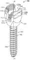
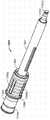
图1是用于微创仪器组的示例实施例的骨锚固件组件或多轴线椎弓根螺钉的第一示例实施例的俯视透视图,其中没有锁定帽(见图11);1 is a top perspective view of a first example embodiment of a bone anchor assembly or polyaxial pedicle screw for an example embodiment of a minimally invasive instrumentation set without a locking cap (see FIG. 11 );
图2是图1的骨锚固件组件或多轴线椎弓根螺钉的正视图;Figure 2 is a front view of the bone anchor assembly or polyaxial pedicle screw of Figure 1;
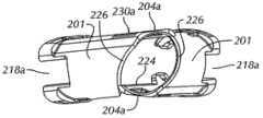
图3是根据仪器组的示例实施例的组织牵开器的侧视透视图;Figure 3 is a side perspective view of a tissue retractor according to an example embodiment of an instrument set;
图4是图3的组织牵开器的侧视透视图,其中,它的可弹性运动臂处于弯曲位置;4 is a side perspective view of the tissue retractor of FIG. 3 with its elastically movable arms in a flexed position;
图5是图1的椎弓根螺钉的侧视透视图,该椎弓根螺钉与图3的组织牵开器连接;5 is a side perspective view of the pedicle screw of FIG. 1 coupled to the tissue retractor of FIG. 3;
图6A是根据仪器组的示例实施例的帽引导仪器的右侧透视图;Figure 6A is a right side perspective view of a cap guiding instrument according to an example embodiment of an instrument set;
图6B是图6A的帽引导仪器的左侧透视图;Figure 6B is a left side perspective view of the cap guiding instrument of Figure 6A;
图7是根据仪器组的示例实施例的反力矩手柄的俯视透视图;7 is a top perspective view of an anti-torque handle according to an example embodiment of the instrument cluster;
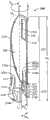
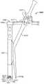
图8是根据仪器组的示例实施例的、图1的椎弓根螺钉、图3的组织牵开器、图6A的帽引导仪器、图7的反力矩手柄和螺丝刀在装配或工作构造中的侧视透视图;8 is a view of the pedicle screw of FIG. 1 , the tissue retractor of FIG. 3 , the cap guide instrument of FIG. 6A , the counter-torque handle of FIG. 7 , and the screwdriver in an assembled or working configuration, according to an example embodiment of an instrument set. side perspective view;
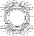
图9是与图3的组织牵开器连接的、图6A的帽引导仪器沿图8中的线9-9的放大剖视图,其中,为了清楚只表示了帽引导仪器和组织牵开器的一部分;9 is an enlarged cross-sectional view of the cap-guiding instrument of FIG. 6A along line 9-9 in FIG. 8 coupled to the tissue retractor of FIG. 3, wherein only a portion of the cap-guiding instrument and tissue retractor are shown for clarity ;
图10A是两个图3的组织牵开器在局部嵌套构造中的侧视透视图;10A is a side perspective view of two tissue retractors of FIG. 3 in a partially nested configuration;
图10B是图11A的两个组织牵开器的俯视透视图;Figure 10B is a top perspective view of the two tissue retractors of Figure 11A;
图10C是在外科手术处理过程中固定在相邻椎骨上的、两个图3的组织牵开器和两个图1的骨锚固件的侧视透视图;10C is a side perspective view of two tissue retractors of FIG. 3 and two bone anchors of FIG. 1 secured to adjacent vertebrae during surgical treatment;
图11是根据示例实施例的、图1的椎弓根螺钉的示例锁定帽的放大正视图;11 is an enlarged front view of an example locking cap of the pedicle screw of FIG. 1 , according to an example embodiment;
图12是根据仪器组的示例实施例的牵开器的正视图,图11的锁定帽安装于其中;Figure 12 is a front view of a retractor according to an example embodiment of the instrument set with the locking cap of Figure 11 installed therein;
图13是根据仪器组的示例实施例的压缩器的正视图,图11的锁定帽安装于其中;FIG. 13 is a front view of a compressor according to an example embodiment of the instrument set, with the locking cap of FIG. 11 installed therein;
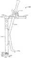
图14是根据示例仪器组的、图1的椎弓根螺钉、图11的组织牵开器以及图12或13的牵开器或压缩器、杆和螺丝刀的侧视图,它们布置成用于外科手术处理过程;14 is a side view of the pedicle screw of FIG. 1 , the tissue retractor of FIG. 11 , and the retractor or compressor, rod, and screwdriver of FIGS. 12 or 13 , arranged for surgical use, according to an example instrument set. surgical procedures;
图15是图1的多轴线骨螺钉的本体的放大俯视图,该多轴线骨螺钉与图3的组织牵开器连接;15 is an enlarged top view of the body of the polyaxial bone screw of FIG. 1 coupled to the tissue retractor of FIG. 3;
图16是用于仪器组的示例实施例的两件式组织牵开器的一个部件的侧视图;16 is a side view of a component of a two-piece tissue retractor for an example embodiment of an instrument set;
图17是与图1的椎弓根螺钉连接的、图16的两件式组织牵开器的侧视透视图;17 is a side perspective view of the two-piece tissue retractor of FIG. 16 coupled with the pedicle screw of FIG. 1;
图18是图6的帽引导仪器的放大仰视图;Figure 18 is an enlarged bottom view of the cap guiding instrument of Figure 6;
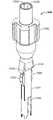
图19A是根据仪器组的示例实施例的剪刀强力工具的侧视透视图;Figure 19A is a side perspective view of a scissors power tool according to an example embodiment of an instrument set;
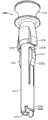
图19B是根据仪器组的示例实施例的螺纹强力工具的侧视透视图;Figure 19B is a side perspective view of a threaded power tool according to an example embodiment of an instrument set;
图20是根据仪器组的示例实施例的拆卸工具的侧视透视图;Figure 20 is a side perspective view of a removal tool according to an example embodiment of the instrument set;
图21A是根据仪器组的示例实施例的螺钉保持器的侧视透视图;21A is a side perspective view of a screw holder according to an example embodiment of an instrument set;
图21B是图21A的螺钉保持器的侧视透视图,其中有处于驱动位置的安全屏蔽件;以及21B is a side perspective view of the screw holder of FIG. 21A with the safety shield in the actuated position; and
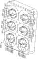
图22是根据仪器组的示例实施例的、用于保持多个图11的锁定帽的帽托盘的俯视透视图。22 is a top perspective view of a cap tray for holding a plurality of locking caps of FIG. 11 according to an example embodiment of an instrument set.
具体实施方式Detailed ways
下面的说明书中使用的某些术语只是为了方便,而不是限定。词语“右”、“左”、“下部”和“上部”表示所参考的图中的方向。词语“内侧”或“远侧”和“外侧”或“近侧”是指分别朝向和远离示例仪器组和它的相关部件的几何中心或方位的方向。词语“前面”、“后面”、“上面”、“下面”、“侧部”、“中间”以及相关词语和/或短语是指所参考的人体中的示例位置和方位,而不是进行限制。术语包括上述词语、其衍生词和类似意思的词。Certain terms used in the following description are for convenience only and not for limitation. The words "right", "left", "lower" and "upper" indicate directions in the drawings to which reference is made. The words "inner" or "distal" and "outer" or "proximal" refer to directions toward and away from, respectively, the geometric center or orientation of the example instrumentation set and its associated components. The words "front", "rear", "above", "below", "side", "middle" and related words and/or phrases refer to example positions and orientations in the human body to which reference is made and are not limiting. The term includes the above words, derivatives thereof and words of similar import.
图1、2和11表示了用于微创脊椎外科手术的示例仪器组的示例骨锚固件组件、多轴线骨螺钉或多轴线椎弓根螺钉100,它包括本体102、锁定帽或骨螺钉帽700和螺纹部分或骨螺钉104。尽管本申请的附图和说明书表示和介绍了示例多轴线骨螺钉100,但是本领域普通技术人员通过阅读本发明申请应当知道,示例仪器组可以变化和改变成用于单轴线骨螺钉(未示出)。示例仪器组还可以变化成操作和用于多种类型的椎弓根螺钉,而并不局限为用于示例椎弓根螺钉100。1, 2 and 11 show an example bone anchor assembly, polyaxial bone screw or
骨螺钉104包括多个螺纹106,用于将多轴线椎弓根螺钉100固定在患者的椎骨V(图14)上。本体102多轴线地安装在骨螺钉104上,以使得骨螺钉104可相对于本体102旋转和枢转。锁定轴环或套夹101安装在本体102内,并在装配结构中定位在本体102和骨螺钉104的头部之间。锁定轴环101方便骨螺钉104相对于本体102进行多轴线运动以及在锁定结构中使得本体102相对于骨螺钉104锁定。可以用于示例微创仪器组的多轴线骨螺钉100的示例在国际专利申请公开No.WO2009/015100(“WO100”)中介绍,该国际专利申请公开No.WO2009/015100的标题为“Polyaxial Bone Fixation Element”,申请日为2009年7月21日,该文献的全部内容结合到本申请中,作为参考。The
多轴线骨螺钉100大致由钛或钛合金构成,例如包括钛、铝和铌的合金(TAN-TI-6Al-6Nb-ASTM F 1295),但是也可以由不锈钢、其它金属合金材料或者几乎任意坚固、刚性、可生物相容的材料(该材料能够呈多轴线骨螺钉100的总体尺寸和形状,并能够承受多轴线骨螺钉100的正常工作状态)来构成。多轴线骨螺钉100(特别是骨螺钉104)可以提供为具有不同长度和/或直径,以便适应特殊患者的解剖学变化和骨结构。骨螺钉104可以沿其中心纵向螺钉轴线X-X为中空插管(未示出),用于将多轴线骨螺钉100定位和布置在Kirschner线或导线(K线)(未示出)(用于将骨螺钉104引导至在椎骨V上的植入部位)上。
本体102包括由两个臂110限定的大致U形杆狭槽或槽道108。套夹101包括杆鞍形件101a,该杆鞍形件101a在装配结构中与杆槽道108对齐,并在锁定结构中接收和接触脊椎杆R(图10C)。杆槽道108在装配结构中终止于套夹101附近,以便形成杆接收部分112,该杆接收部分112的尺寸设置成容纳杆R(图10C)。各臂110包括内表面110a,该内表面110a有螺纹部分114,该螺纹部分114在装配结构中定位成远离骨螺钉104。各臂110的外表面110b通常包括其中的凹口116。
参考图1-5、9和10A-10C,用于微创脊椎外科手术的示例仪器组的组织牵开器200(与骨锚固件组件100一起使用)包括本体201,该本体201有远端部分202、近端部分204以及在该近端和远端部分202、204之间延伸的纵向组织牵开器轴线L-L。本体201包括在远端部分202处的第一狭槽和第二狭槽218a、218b以及第一和第二纵向延伸边缘224、226,该第一和第二纵向延伸边缘224、226在远端部分202处限定了第二狭槽218b。纵向延伸边缘224、226在远端部分202和近端部分204之间延伸。第一纵向延伸边缘224大致平行于组织牵开器200的纵向组织牵开器轴线L-L,但是并不这样限制,它可以沿几乎任意路径延伸,或者包括在沿它的长度的方向上的变化,以便使得组织牵开器200的设计适合特殊用途。第二纵向延伸边缘226在远端部分202处大致平行于纵向组织牵开器轴线L-L,并从在远端部分202附近的弯折点217朝着近端部分204弯曲成螺旋状形状,使得组织牵开器200具有比封闭或基本封闭的套管或套筒更小的结构。这样,组织牵开器200可以在皮肤切口I处向外科医生提供更宽的视线,并限制了组织牵开器202的材料,特别是在皮肤切口I附近。限制组织牵开器200的仪器等级不锈钢或其它很难成像的材料的量将不仅可以向外科医生提供改进的视线,还可以在外科医生对具有安装在多轴线骨螺钉100上的组织牵开器200的脊椎构件进行成像时减少对成像系统(例如荧光镜)的干扰量。而且,减少组织牵开器200的、从皮肤切口I向外伸出的材料量将大大减小皮肤切口I的尺寸。Referring to Figures 1-5, 9 and 10A-10C, a
本体201通常由仪器等级的不锈钢构成,但是也可以由钛、铝、金属合金、聚合物材料、复合材料或者几乎任意相对刚性、坚固的可生物相容的材料(该材料能够呈组织牵开器200的总体形状,并能够承受组织牵开器200的正常工作状态)来构成。局部通路206在远端和近端部分202和204之间纵向延伸,并由第一和第二纵向延伸边缘224、226以及本体201的内表面201a来限定。由于第二纵向延伸边缘226的螺旋形形状,该局部通路206沿组织牵开器200的大部分长度几乎完全暴露,使得组织牵开器200用于牵开组织,如后面更详细所述。The
本体201大致限定了绕纵向组织牵开器轴线L-L的周边。本体201包括:第一部分220,该第一部分220邻近远端部分202;以及第二部分222,该第二部分222从近端部分204纵向延伸至弯折点217。近端部分204的末端部分204a具有大致线性和稍微弯曲的截面。本体201还包括至少一个(但是通常为两个)切割狭槽208,该切割狭槽208沿本体201的、在远端部分202近侧的部分大致纵向延伸。两个切割狭槽208在远端部分202的近侧布置成彼此相对。各切割狭槽208包括一对近端部分208a和远端部分208b。可弹性运动的臂210由各切割狭槽208来限定。臂210通过偏转区域211而在切割狭槽208的近端部分208a处可运动地附接在本体201上,尽管也可以使用其它结构来将臂210附接在本体201上,例如弹簧偏压铰链,或者允许臂210相对于本体201枢转或弯曲的可选机构。本体201还包括在近端部分204附近的窗口230,该窗口230可以用于使得组织牵开器200与各种工具和/或仪器接合或可拆卸地连接,如后面更详细所述。
当在装配结构与多轴线骨螺钉100连接时(图5),组织牵开器200与多轴线骨螺钉100可拆卸地连接,并可旋转地固定在多轴线骨螺钉100上。在装配结构中,本体201的内表面201a的一部分接收和接触本体102的臂110的外表面110b的一部分,从而限制多轴线骨螺钉100的本体102在与纵向轴线L垂直的平面内相对于组织牵开器200运动。组织牵开器200还包括至少一个(通常为4个)螺钉接合肋214(图3-5和8),该螺钉接合肋214从远端部分202朝着纵向组织牵开器轴线L-L纵向向内延伸,并大致朝向局部通路206。多轴线骨螺钉100的本体102包括相应数目的互补轴环槽118(图1和2),该互补轴环槽118从本体102的近端部分102a纵向延伸。当组织牵开器200与多轴线骨螺钉100连接时,各螺钉接合肋214与一个相应轴环槽118匹配,以使得远端部分202包围和抓住臂110,从而限制至少本体102绕纵向轴线L的旋转。不过,当组织牵开器200安装在本体102上时,组织牵开器200和本体102可相对于骨螺钉104枢转和旋转,至少直到本体102相对于骨螺钉104锁定,如后面更详细所述。螺钉接合肋214与轴环槽118的接合提供了相对较大的厚度,特别是在膨大部分203处(相对于本体201的其余部分),使得组织牵开器200的远端部分202和(特别是)螺钉接合肋214能够对抗由于锁定帽700最终紧固在本体102上而产生的最终紧固力,如后面更详细所述。When connected to the
组织牵开器200的臂210包括位于各切割狭槽208的远端部分208b附近的附接凸片212,该附接凸片212朝着纵向组织牵开器轴线L-L大致横向向内凸出。臂210有松弛部分(图3和5),其中,当骨锚固件组件100和组织牵开器200处于装配结构时,附接凸片212位于骨锚固件组件100的本体102的凹口116中(图5)。因此,当组织牵开器200安装在本体102上时,该本体102在局部通路206内沿纵向组织牵开器轴线L的纵向运动将受到限制。臂210还有弯曲位置(图4),其中,臂210从组织牵开器200向外偏转,因此使得附接凸片212与骨锚固件组件100的凹口116间隔开,以便允许组织牵开器200从本体102上纵向拆卸或者允许附接凸片212运动至凹口116中,而并不受到本体102的锁定边缘117的干涉或阻挡。The
当组织牵开器200在螺钉接合肋214位于轴环槽118内的情况下与本体102接合时,组织牵开器200相对于本体102的运动的5个自由度通过接合肋214与轴环槽118的接合而受到限制。具体地说,通过接合肋214与轴环槽118的接合,组织牵开器200大致在任何旋转运动和任何平移运动中受到限制,除了沿纵向组织牵开器轴线L-L离开本体102的运动以外。附接凸片212与凹口116和/或锁定边缘117的接合大致阻止组织牵开器200沿纵向组织牵开器轴线L-L远离本体102的运动以及组织牵开器200相对于本体102的最后可能的运动自由度。附接凸片212的尺寸和形状可以设置成这样,当附接凸片212定位在凹口116中时,该附接凸片212并不向本体102的侧部施加夹持力,因为附接凸片212可以设置成在接合位置中阻止组织牵开器200远离本体102的轴向运动,与任何另外的自由度不同。因此,附接凸片212可以只通过在附接凸片212和凹口116的锁定边缘117之间的干涉来阻止组织牵开器200远离本体的运动。When the
组织牵开器200还大致包括在本体201的远端部分202近侧的至少一个保持凸片216,该保持凸片216从内表面201a凸出至局部通路206中。保持凸片216通常位于活动臂210的内表面上并在附接凸片212的近侧或上面。不过,保持凸片216可以位于局部通路206内的其它位置。当骨锚固件组件100与组织牵开器200连接时,本体102的近端部分102a抵靠保持凸片216(图5),从而防止骨锚固件组件100沿纵向轴线L进一步运动至局部通路206中。The
组织牵开器200还包括形成于远端部分202处的至少一个(通常第一和第二)狭槽218a、218b,该狭槽218a、218b从远端部分202朝着近端部分204纵向延伸。示例实施例的第一狭槽218a并不延伸组织牵开器200的整个长度,并终止于封闭端部部分219处。当多轴线骨螺钉100与组织牵开器200连接时,第一狭槽和第二狭槽218a、218b与本体102的杆槽道108对齐。第二狭槽218b通过本体201的第一和第二纵向延伸边缘224、226而限定于本体201的第一部分220中,该第一和第二纵向延伸边缘224、226绕周边分开第一预定距离D1。在本体201的第二部分222中在弯折点217和近端部分204之间,绕假想周边在第一边缘和第二边缘224、226之间的距离沿纵向组织牵开器轴线L-L从第一预定距离D1增加至在本体201的近端部分204处的第二预定距离D2。第一边缘224大致线性,并沿第二部分222的长度在周边上保持在相对固定位置,而第二边缘226沿第二部分222的长度以曲线或螺旋状方式逐渐远离地运动,以便在近端部分204处或附近产生更大距离D2。例如,图3和4中所示的组织牵开器200对第二边缘226有螺旋状切割部,尽管也可以使用其它切割部,例如线性倾斜部、锥形部、曲线形部等。而且,第一边缘和第二边缘224、226可以有螺旋状形状,而不会明显影响示例仪器组的组织牵开器200的功能。The
参考图3-5和10A-10C,如使用中所示,组织牵开器200可以减小在外科手术处理过程中在运动段M处进行的侵入,该运动段M包括患者脊椎的上部椎骨和下部椎骨V。例如,在示例实施例中,具有局部通路206和螺旋状第二边缘226的两个组织牵开器200安装在多轴线骨螺钉100上,并彼此相向成角度成嵌套或局部嵌套结构(图10A-10C),这可以减小皮肤切口I的尺寸。具体地说,组织牵开器200的相对开口近端部分204能够在皮肤切口I处嵌套,以使得需要相对较小的皮肤切口I。通常,当这些普通的封闭微创套筒或套管的截面在皮肤切口高度处形成至少图形8时,封闭的微创套筒或套管需要容纳至少两倍于单个套筒或套管直径的切口。相反,容纳嵌套的组织牵开器200所需的皮肤切口I可以小于一个组织牵开器200的整个直径,因为在嵌套结构中,组织牵开器200有镜像的弓形或孔眼形形状(图10B)。此外,患者的软组织T将朝着嵌套结构偏压组织牵开器200。而且,组织牵开器200可以由外科医生而从嵌套结构分开,或者以与牵开器类似方式来展开皮肤切口I,或者使得软组织T运动以改变皮肤切口I的位置,从而使得外科医生对于结构元件或外科手术部位的特殊区域的视线最大,只要本体102保持可相对于骨螺钉140进行多轴线旋转。Referring to FIGS. 3-5 and 10A-10C , as shown in use,
组织牵开器200通常具有高度HT,该高度HT稍微大于在椎骨V处的植入多轴线骨螺钉100至皮肤切口I的距离。因此,组织牵开器200只稍微伸出至皮肤切口I的外部,这可以增加进入大致圆锥形切口CI的视线,用于观察外科手术部位和受影响的运动段M。组织牵开器200还相对简单地利用卡扣作用而附接在多轴线骨螺钉100上,如上面所述,且它是单件结构,由外科医生以与牵开器刀片类似的方式附接在本体102上以便使用。The
大致圆锥形的切口CI能够制成为穿过患者的软组织T,以便接近运动段M。由于螺旋状的第二边缘226,大致圆锥形的切口CI由于组织牵开器200在它们的近端部分204处嵌套而成为可能。形成的嵌套能够有相对长圆形或孔眼形的单个皮肤切口I(图10B和10C)。而且,组织牵开器200的尺寸大致设置成只从皮肤切口I稍微伸出,以便进一步限制结构和对外科医生的视线的相对干扰。A generally conical incision CI can be made through the soft tissue T of the patient to access the segment of motion M. As shown in FIG. Due to the helical
两个骨锚固件组件100能够分别通过K线(未示出)而引导穿过大致圆锥形切口CI至上部椎骨和下部椎骨V,并螺纹连接至椎骨V中。外科医生可以通过利用由Longissimus和Multifidus肌引导的手指进行钝器解剖来产生圆锥形切口CI,这可以将外科医生引导向上部椎骨和下部椎骨V的椎弓根。特别参考图10A-10C,组织牵开器200还可以在骨锚固件组件100插入大致圆锥形切口CI内的同时穿过该大致圆锥形切口CI插入,或者可以在将骨锚固件组件100安装在椎骨V上之后与骨锚固件组件100随后连接。骨锚固件组件100可以在组织牵开器200安装或没有安装于其上的情况下穿过圆锥形切口CI插入,但是组织牵开器200通常在插入大致圆锥形切口CI内的过程中安装在骨锚固件组件100上。当组织牵开器200牵开或保持患者的软组织T离开杆R时,该杆R穿过大致圆锥形切口CI插入。使用安装在多轴线骨螺钉100上的组织牵开器200使得外科医生能够枢转和旋转组织牵开器200的近端部分204至多个不同方位和位置,以便最大化通向外科手术部位的视线,因为软组织T稍微有弹性和柔顺性,以使得外科医生可以操纵或以其它方式移动皮肤切口I和圆锥形切口CI。使用普通的微创脊椎仪器(其中,管、套筒或套管以预定结构固定在一起),通常不能这样操纵切口I、CI,因为从多轴线骨螺钉伸出的管、套筒或套管锁定在一起,从而防止操纵切口的位置、尺寸和/或方位。Two
用于利用示例仪器组的一级外科手术的组织牵开器200的切口通常称为微开口切口。示例的微开口切口使得外科医生通过单个大致圆锥形切口CI来工作,且至少两个多轴线骨螺钉100和脊椎杆R包含在构件中。大致圆锥形切口CI的皮肤切口I可以用于通过单个微开口中线切口来将一级、两级或另外级的构件安装至两个侧部椎弓根中,即通过在中线的各侧越过肌肉平面操纵切口I、CI,并沿软组织T的肌肉平面来解剖运动段M。The incision of the
参考图16和17,当外科手术横过至少两个运动段M来进行时,第一和第二组织牵开器300a、300b可以安装在中心骨螺钉100上。在装配结构中,第一和第二组织牵开器300a、300b限定了两件式组织牵开器300,该两件式组织牵开器300可以用于中心或其它内侧定位的骨螺钉100。第一和第二组织牵开器300a、300b与上述单件式牵开器200类似。相同参考标号用于相同元件,除了300系列标号用于第一和第二组织牵开器300a、300b。因此,各组织牵开器300a、300b的完整说明将省略,只介绍区别。在示例实施例中,两件式组织牵开器300包括第一组织牵开器300a和第二组织牵开器300b,各组织牵开器可与多轴线骨螺钉100的本体102的相应一个臂100可拆卸地连接。第一和第二组织牵开器300a、300b各自包括本体301,该本体301有限定纵向轴线L-L的远端部分302和近端部分304以及限定于该近端和远端部分304、302之间的局部通路306。当与多轴线骨螺钉100连接时,第一和第二组织牵开器300a、300b阻挡住软组织T,从而产生空隙307,该空隙307允许杆R插入患者体内。第一和第二组织牵开器300a、300b可以单独用于骨螺钉100,但是一对第一和第二组织牵开器300a、300b用于骨螺钉100将用于限定从切口I至骨螺钉100的空隙,以便适应将杆R引入骨螺钉100中。Referring to Figures 16 and 17, first and
第一和第二组织牵开器300a、300b各自包括内表面301a,该内表面301a的一部分接收和通常接触相应一个臂110的外表面110b的一部分,与上面对于单件式组织牵开器200所述的连接类似。内表面301a可以有曲率,以便限定局部通路306。类似的,第一和第二组织牵开器300a、300b各自包括:可弹性运动的臂310,该臂310由本体301的切割狭槽308来限定;螺钉接合肋314;以及保持凸片316,它们的功能与单件式组织牵开器200的相应部分类似,且不再详细介绍。当与多轴线骨螺钉100连接时,第一和第二组织牵开器300a、300b形成至少一个杆槽道318,该杆槽道318从远端部分302纵向延伸至近端部分304。在装配结构中,装配的第一和第二组织牵开器300a、300b的杆槽道318与杆槽道108对齐。The first and
参考图3-6B、8和9,示例帽引导仪器400包括大致圆柱形套筒401,该圆柱形套筒401有远端部分402、近端部分404以及沿纵向引导轴线G-G在远端和近端部分402、404之间延伸的大致圆柱形空心空腔406。帽引导件400大致由仪器等级不锈钢构成,但是也可以由钛、铝、金属合金、聚合物材料、复合材料或者几乎任意相对刚性、坚固和可生物相容的材料(该材料能够呈帽引导件400的总体形状,并能够承受帽引导件400的正常工作状态)来构成。帽引导件400和示例仪器组的任意附加部件可以特别地由铝、铝合金或聚合物材料来构成,特别是当希望提高成像相容性时。3-6B, 8, and 9, an example
帽引导件400设置成在局部通路206内与组织牵开器200可拆卸地连接,以使得局部通路206和空心空腔406同轴对齐,且纵向组织牵开器轴线L-L和纵向引导轴线G-G同轴(图8)。至少一个狭槽410形成于帽引导件400的远端部分402处,该狭槽410沿该帽引导件的一部分大致纵向延伸。狭槽410由从套筒401向远侧延伸的臂422来限定。各臂422包括弓形空腔424,用于在锁定帽700的插入过程中接触杆R(图19),同时引导(reduction)该杆R进入本体102的杆狭槽108中。当帽引导件400与组织牵开器200连接时,狭槽410与一个可弹性运动的臂210对齐。帽引导件400相对刚性和坚固,特别是当与组织牵开器200相比时,以便对抗该帽引导件400在将锁定帽700最终紧固于本体102上时遇到的负载。相对刚性和坚固的帽引导件400也能够在最终紧固的过程中通过对抗在最终紧固中的相对较高负载而限制对示例仪器组的其它部件的损害,例如组织牵开器200、本体102、锁定帽700或者示例仪器组的任意其它部件。帽引导件400和示例仪器组的其它部件遇到的最大负载和应力是在最终紧固过程中,且帽引导件400构成为承受该负载状态,以便保护示例仪器组的其它部件,这些部件中的某些设计成最大化外科医生的视线,并随后有相对较低的刚性和强度。因此,在处理过程中当需要刚性、坚固的结构来对抗最终紧固力时(而不是在处理过程中当与增加强度相比更希望增加可视性时),期望帽引导件400处在切口I、CI中。
帽引导件400还包括在近端部分404处的两个标记432,这两个标记432与在远端部分402处的弓形空腔424对齐。当锁定帽700插入本体102中以及帽引导件400插入局部通路206中时,标记432向外科医生提供了用于弓形空腔424与杆R对齐的视觉指示,以便保证弓形空腔424与杆R接合以及将该杆R推入本体102的U形杆狭槽或槽道108中。当没有标记432时,外科医生将很难在外科手术过程中使得弓形空腔424与杆R视觉对齐,因为在微创处理过程中帽引导件400、组织牵开器200和患者的软组织T通常阻挡外科医生通向外科手术部位的视线。当锁定帽700与帽引导件400接合时,标记432还帮助使得锁定帽700的鞍形件部分704与杆R对齐。压缩器1100、分散器1000、拆卸器或拆卸工具1200、保持器1300或者引入局部通路206中的其它类似仪器可以包括在它们的近端部分处的类似标记,以便帮助外科医生使得仪器与在外科手术部位处的构件正确对齐。
帽引导件400还包括至少一个(通常4个)阻挡凸片408,该阻挡凸片408在远端部分402的近侧。当与组织牵开器200连接时,阻挡凸片408由组织牵开器200的至少一个(通常4个)阻挡肋228来接收(图9)。在存在由骨螺钉100施加在组织牵开器200的内表面201a上的力的情况下,阻挡凸片408通常与相应阻挡肋228的内表面228a接触。阻挡肋228通常定位成靠近螺纹接合肋214并在组织牵开器200的远端部分202处的相对狭窄膨大部分中。因此,由组织牵开器200对抗的任何最终紧固力从本体102通过螺钉接合肋214、通过组织牵开器200在远端部分202处的较短或较窄膨大部分203、通过阻挡肋228而直接到达帽引导件400的坚固和刚性的圆柱形套筒401中。因此,最终紧固力通过将力立即引导到帽引导件400中(通过使得力传递经过组织牵开器200在远端部分202处的较短膨大部分203),而基本使相对较薄的组织牵开器200不受到该力。因此,在锁定帽700的插入过程中,帽引导件400限制了多轴线骨螺钉100的本体102和组织牵开器200的张开。
间隙可以限定于阻挡凸片408和相应阻挡肋228的内表面228a(图9)之间,以便通过提供用于使得阻挡凸片408插入在阻挡肋228和组织牵开器200的本体201之间的间隙中的空隙而适应帽引导件400滑动插入组织牵开器200内。间隙相对较小,以便当组件受到最终紧固力时限制组织牵开器200和本体102的张开。A gap may be defined between the blocking
引导按钮426在远端部分402的近侧从圆柱形套筒401的侧部径向向外延伸。引导按钮426具有按钮宽度WB,该按钮宽度WB稍微小于第二狭槽218b的狭槽宽度WS(图4)。引导按钮426还包括相对平滑、弓形的角部428,特别是在远端部分上。当帽引导件400插入组织牵开器200的局部通路206中时,引导按钮426自引导和使得帽引导件400定向成与组织牵开器200正确对齐。例如,如果帽引导件400引入局部通路中,以使得引导按钮424初始接触第二纵向螺旋形边缘226,则引导按钮424沿第二螺旋形边缘226向下滑动,直到引导按钮426落入第二狭槽218b中。当引导按钮426在装配结构中位于第二狭槽218b内时,弓形空腔424和标记432与杆R对齐,阻挡凸片408位于阻挡肋228和本体201之间,大致在四个位置,以便限制组织牵开器200和本体102的张开。此外,引导按钮426、臂422和阻挡凸片408可以配合,以便固定帽引导件400相对于组织牵开器200的六个自由度中的五个,除了帽引导件400沿纵向组织牵开器轴线L-L离开组织牵开器200的远端部分202离开局部通路206的运动。A
防张开翼板440在近端部分404附近从套筒401径向向外延伸,并限定在套筒401和远侧翼板端部部分440a之间的捕获槽442。在装配结构中,当帽引导件400定位在局部通路206中,且阻挡凸片408位于阻挡肋228和本体201之间时,在组织牵开器200的近端部分204处的末端部分204a位于捕获槽442内,以便限制近端部分204在使用过程中向外张开。两个防张开翼板440可以例如与两件式牵开器300一起使用,以便分别与第一和第二组织牵开器300a、300b的近端部分接合。
帽引导件400通常还包括在近端部分404附近在各侧的空隙窗口450和捕获槽460。空隙窗口450和捕获槽460与示例仪器组的附加仪器一起使用,以便操纵或使得帽引导件400与其它仪器对齐,这将在后面更详细介绍。The
参考图8和11,螺丝刀500可以用于多轴线骨螺钉100、组织牵开器200和帽引导件400的组件,用于将锁定帽700(图12)螺纹固定在多轴线骨螺钉100的本体102上。螺丝刀500包括手柄502和从该手柄伸出的驱动轴504。驱动轴504的直径小于在帽引导件400内的空心空腔406的直径。因此,当位于帽引导件400中时,驱动轴504可相对于帽引导件400旋转。驱动轴504有末端部分(未示出),该末端部分设置成与以可释放和可旋转固定的方式与在锁定帽700顶部的驱动结构701匹配。Referring to FIGS. 8 and 11 ,
参考图6A-8,反力矩手柄600有抓紧端部部分602和互锁端部部分604。互锁端部部分604包括仪器相接部606,该仪器相接部606可释放地定位在近端部分404处的空心空腔406内(图6B)。当插入空心空腔406内时,仪器相接部606和(因此)反力矩手柄600可旋转地相对于帽引导件400固定。仪器相接部606包括大致平滑内表面606a和在外表面上的至少一个花键606b,该花键606b与在帽引导件400的近端部分404处的空心空腔406中的互补花键412匹配。该至少一个花键606b和互补花键412可以包括八边形花键或具有八个侧部的花键,它们设置成使得抓紧端部部分602与标记432和杆R对齐,定位成与标记432和杆垂直,或者相对于标记432和杆R定向成45度(45°)。因此,外科医生可以使得抓紧端部部分602定向成大致垂直于外科医生、大致离开外科医生指向、大致朝着外科医生指向、或者定向成朝着和/或离开外科医生成45度(45°)。这些方位使得反力矩手柄600能够适合左手和右手的外科医生、由助手握住和/或通常使得外科医生方便。外科医生可以方便地利用这些各种方位,或者使得助手来保持反力矩手柄600。花键606b和互补花键412也可以设置成具有几乎任意数目的侧部,例如可分成4个正方形花键,使得外科医生有至少四个方位来使得反力矩手柄600相对于帽引导件400或其它仪器定位。Referring to FIGS. 6A-8 , the torque reaction handle 600 has a
互锁端部部分604还包括端部开口狭槽610,该端部开口狭槽610的宽度大于驱动轴504的直径。因此驱动轴504不仅可在反力矩手柄600的端部开口狭槽610内旋转,而且当驱动轴504在帽引导件400的空心空腔406内时和当帽引导件400在组织牵开器200的局部通路206内时反力矩手柄600可插入帽引导件400和可从该帽引导件400中取出。因此,锁定帽700的插入、紧固和反力矩操作可以在并不过多取出和更换仪器的情况下进行,且当帽引导件需要最终紧固时,反力矩手柄600能够与帽引导件400接合。此外,由于组织牵开器200和帽引导件400的设置以及它们的相互接合和与本体102的接合,提供于反力矩手柄600和多轴线椎弓根螺钉100的本体102之间的牢固接合相对刚性和坚固。具体地说,组织牵开器200基本上不受到最终紧固负载,除了在远端部分202处在螺纹接合肋214和阻挡肋228之间的膨大部分203处,在该位置处,组织牵开器200包括额外的强度和刚性,以便对抗负载。因此,用于最终紧固所需的仪器(包括组织牵开器200、帽引导件400和反力矩手柄600)在最终紧固处理过程中至少位于大致圆锥形切口CI附近,并可以在处理过程的可选步骤中快速拆卸和改变。帽引导件400并不特别是构件的最终紧固所必须的,因为最终紧固也可以通过分散器1000、压缩器1100、螺纹强制工具(threaded persuader)150或者其它相关仪器(该仪器与本体102接合,接收螺丝刀500和反力矩手柄600,并能够保持锁定帽700)来进行。The interlocking
仪器相接部606还可以设置成使得至少一个花键606b限定于内表面606a中,用于抓住在帽引导件400的外表面上的互补花键412(未示出)。这样的结构使得端部开口狭槽610能够适应反力矩手柄600与帽引导件400的快速接合和释放,而并不从切口I中取出螺丝刀500或其它仪器。The instrument interface 606 may also be configured such that at least one
下面参考图11,锁定帽700通常由钛或钛合金(例如包括钛、铝和铌的合金(TAN-TI-6Al-6Nb-ASTM F 1295))来构成,但是也可以由不锈钢、其它金属合金材料或者几乎任意坚固、刚性和可生物相容的材料(该材料能够呈锁定帽700的总体尺寸和形状,并能够承受锁定帽700的正常工作状态)来构成。锁定帽700包括螺纹部分702和可旋转地安装在该螺纹部分702上的鞍形件704。鞍形件704大致机械加工有柱(未示出),该柱与螺纹部分702中的轴向孔(未示出)匹配,并可旋转地固定在该轴向孔上。锁定帽700大致在WO 100中所示,且并不局限于包括鞍形件704和螺纹部分702的结构。例如,锁定帽700可以包括本领域普通技术人员已知的几乎任意类型或种类的锁定帽。螺纹部分702包括多个螺纹712,该螺纹712与在多轴线骨螺钉100中的本体102的臂110的内表面110a的螺纹部分114匹配。鞍形件部分704包括两个向下延伸的臂706、708,这两个臂706、708形成在它们之间的弓形空腔710。鞍形件704包括有槽表面704a,该有槽表面704a帮助将鞍形件704固定在处于植入和锁定位置的杆R上。当锁定帽700安装在多轴线骨螺钉100上时,空腔710的尺寸和形状设置成互补地接收杆R。Referring now to Figure 11, the locking
参考图6A、6B、11和18,锁定帽700可拆卸地插入帽引导件400的空心空腔406的远端部分中,且当锁定帽700固定在帽引导件400上时,鞍形件704可相对于帽引导件400和螺纹部分702旋转。为了容纳锁定帽700,示例帽引导件400包括可运动帽凸片414(图18),该可运动帽凸片414位于帽引导件400的远端部分402的近侧,并凸出至空心空腔406中。帽凸片414布置在帽引导件400的可弹性运动臂416的远端部分418处(图6)。可运动臂416在它的近端部分420处附接在帽引导件400的套筒401上。帽凸片414可以选择地包括螺纹部分(未示出),该螺纹部分凸出至空心空腔406中,以便与锁定帽700的螺纹部分702接合以及将锁定帽700固定在帽引导件400的远端部分402上。而且,帽引导件400可以包括附加可选机构,以便将锁定帽700暂时固定在帽引导件400的空心空腔406中,例如钩和环材料、粘接剂材料、夹、可释放的紧固件等机构。6A, 6B, 11 and 18, the locking
在示例实施例中,可运动臂416由弹簧钢材料构成,并在近侧周边边缘416a处焊接在帽引导件400上。间隙416b限定于可运动臂416和帽引导件400之间并在可运动臂416的远侧周边处,使得可运动臂416的远端部分418可以弯曲,以便在锁定帽700插入空心空腔406和从该空心空腔406取出的过程中分别接收和释放锁定帽700。锁定帽700通过帽引导件400的狭窄部分409(图18)来防止过度插入空心空腔406中,该狭窄部分409在远端部分402的近侧径向向内延伸到空心空腔406中,并抵靠锁定帽700的顶表面702a,以便使得纵向帽轴线C-C与帽引导件400的纵向引导轴线G-G对齐。当在装配结构中锁定帽700插入和固定在帽引导件400的空心空腔406中时,帽凸片414接收于锁定帽700的螺纹部分702的螺纹712中。In an example embodiment,
在锁定帽700在帽引导件400的空心空腔406中的情况下,帽引导件400定位在组织牵开器200中,以使得局部通路206和空心空腔406同轴对齐,且使得锁定帽700与多轴线骨螺钉100的本体102同轴对齐。在这种装配结构中,纵向帽轴线C-C与纵向组织牵开器轴线L-L和纵向引导轴线G-G大致同轴。这种结构使得锁定帽700的螺纹部分702能够与本体102的螺纹部分114匹配,而不会螺纹错扣等,因为当帽引导件400在组织牵开器200内合适锁定就位时(图8),帽引导件400和锁定帽700的对齐自动提供了锁定帽700的螺纹部分702与本体102的螺纹部分114的竖直对齐。优选是,在该装配结构中(图8),螺丝刀504的驱动轴504也与纵向组织牵开器轴线L-L、纵向引导轴线G-G和纵向帽轴线C-C同轴对齐。With the
参考图6A、6B、8和12-14,其它仪器例如压缩器1100、分散器1000、拆卸工具1200、保持器1300等可以结合示例仪器组来使用,这也限制了在插入和最终紧固锁定帽700(以便将杆R锁定在多轴线骨螺钉组件100中和使得骨螺钉104相对于本体102锁定)时的张开、螺纹错扣和其它不利结果。例如,压缩器1100和/或分散器1000具有多个与帽引导件400类似的结构特征,特别是在它们的远端部分处,以便与组织牵开器200和锁定帽700接合。因此,相同参考标号用于相同元件,除了1000系列标号用于识别分散器1000的特征外,1100系列标号用于识别压缩器1100的特征。因此,省略压缩器1100和分散器1000的示例实施例的完整说明,只介绍值得注意的差异。压缩器1100和分散器1000包括帽引导件400的多个特征,同时保持它们能够在相邻多轴线骨螺钉100之间进行分散和压缩的特殊特征,这些特殊特征为本领域普通技术人员已知,用于压缩器1100和分散器1000的功能。因此,尽管在本申请中介绍了帽引导件仪器400用于在脊椎外科手术中执行多个功能,但是压缩器1100和分散器1000或者其它类似仪器也可以在合适时代替它。Referring to Figures 6A, 6B, 8 and 12-14, other instruments such as
参考图12-14,分散器1000和压缩器1100都包括:棘齿臂1017、1117;枢转臂1019、1119,该枢转臂1019、1119可枢转地安装在圆柱形套筒1001、1101上;以及棘齿机构1021、1121,该棘齿机构1021、1121能够用于使得枢转臂1019、1119相对于圆柱形套筒1001、1101锁定或者使得枢转臂1019、1119相对于圆柱形套筒1001、1101机械运动。分散器1001包括在枢转臂1019的远端部分处的钝头端部部分1019a,压缩器1100包括在它的枢转臂1119的远端部分处的钩形端部部分1119a。在使用中,分散器1000的钝头端部1019a抵靠相邻多轴线螺钉100的锁定帽700的侧表面,而圆柱形套筒1001固定在其它多轴线螺钉100上,螺钉100被彼此远离地推压,通常以便减轻在两个相邻椎骨V之间的神经上的压力。相反,压缩器1100的钩形端部部分1119a对着螺钉100(圆柱形套筒1101附接在该螺钉100上)穿过组织牵开器200的第一狭槽和第二狭槽218a、218b延伸。钩形端部1119a与该螺钉100的锁定帽700接合,并将多轴线螺钉100和相邻椎骨V朝着彼此推压,以便将椎骨V压缩在一起,或者压靠在位于椎骨V之间的间隔件S(图10C)上。12-14, both the
参考图3-6B、8和19A,本申请的示例仪器组包括剪刀强力工具1400,该剪刀强力工具1400有:槽接合臂1402,该槽接合臂1402附接在第一把手1460a上;窗口接合前端1404,该窗口接合前端1404固定在第二把手1460b上;以及释放凸片1406。当多轴线螺钉100在组织牵开器200安装于其上的情况下插入椎骨V中时,杆R定位在杆狭槽108中,且具有锁定帽700(该锁定帽700固定在帽引导件400的远端部分402处)的帽引导件400定位在局部通路206中,杆R可能在某些情况下很难完全设置在杆鞍形件101a中。另外,外科医生只用手或人力可能很难将杆R足够远地推入杆狭槽108中以便使得螺纹部分702的螺纹712与臂110的螺纹部分114初始接合。剪刀强力工具1400可以用于施加机械力,以便将帽引导件400向下推压至组织牵开器200的局部通路206中,从而将杆R推入杆狭槽108内和/或使得螺纹部分702的螺纹712与臂110的螺纹部分114接合。Referring to Figures 3-6B, 8 and 19A, an exemplary instrument set of the present application includes a scissors power tool 1400 having: a slot engaging arm 1402 attached to a first handle 1460a; a window engaging front end 1404, the window engaging front end 1404 is secured to the second handle 1460b; and a release tab 1406. When
在使用中,槽接合臂1402定位在抓取槽460中,窗口接合前端1404与组织牵开器200的窗口230的近端接合。第一和第二把手1460a、1460b挤压在一起,以便将槽接合臂1402推向窗口接合前端1404,并将帽引导件400进一步推入组织牵开器200的局部通路206中。向下推压帽引导件400使得锁定帽700将杆R向下推入杆狭槽108中。剪刀强力工具1400可以在并不阻碍螺丝刀500的驱动轴504插入空心空腔406中和与锁定帽700的驱动结构701接合的情况下使用。此外,剪刀强力工具1400并不阻碍反力矩手柄600与帽引导件400的接合。当迫使帽引导件400相对于组织牵开器200处于装配或工作结构时,强力工具1400锁定就位,以使得外科医生不必继续保持第一和第二把手1460a、1460b以便保持帽引导件400相对于组织牵开器200的位置。为了释放剪刀强力工具1400的锁定,驱动释放凸片1406,且剪刀强力工具1400可以脱开与帽引导件400和组织牵开器200的接合。空隙窗口450与组织牵开器200的窗口230对齐的位置将在操作时提供了用于窗口接合前端1404的空隙。In use, the slot engaging arm 1402 is positioned in the
参考图1-8和19B,通常在剪刀强力工具1400的行程不足以迫使杆R时,螺纹强力工具1500可以用于同样迫使杆R进入杆狭槽108中。螺纹强力工具1500包括:在相对侧的弹簧臂1502;滑动器1504,该滑动器1504以与上述帽引导件400类似的方式与锁定帽700可释放地接合;手促动器1506,该手促动器1506在螺纹强力工具1500的近端处,以便使得滑动器1504相对于圆柱形套筒1501运动;防张开翼板1540;以及内部花键1508,用于与反力矩手柄600的花键606b接合。Referring to FIGS. 1-8 and 19B , typically when the stroke of the scissors power tool 1400 is insufficient to force the rod R, the threaded
在使用时,如果杆R的位置高出杆狭槽108之上足够距离,使得剪刀强力工具1400不能使得帽引导件400与组织牵开器200接合以迫使(persuade)杆R进入,或者剪刀强力工具1400不能施加足够力来迫使杆R进入,则螺纹强力工具1500可以引入局部通路206中,并以与帽引导件400类似的方式在远端部分202的近侧与组织牵开器200接合。当完全装配和设置在组织牵开器200中时,弹簧臂1502向外弹入组织牵开器200的窗口230或单个窗口230中,使得螺纹强力工具1500可沿纵向组织牵开器轴线L-L平移地相对于组织牵开器200和多轴线螺钉100固定。手促动器1506相对于圆柱形套筒1501旋转,以使得滑动器1504向下朝着远端运动,且鞍形件704与杆R接合。手促动器1506的进一步枢转将滑动器1504进一步推向远端,并迫使杆R进入杆狭槽108中,迫使螺纹部分702的螺纹712与臂110的螺纹部分114接合。将杆R推入杆狭槽108中的推压力通过组织牵开器200来对抗以及通过弹簧臂1502传递至圆柱形套筒1501中。当迫使杆R进入足够量,以便使得螺纹部分702的螺纹712与臂110的螺纹部分114接合时,螺丝刀500的驱动轴504通过螺纹强力工具1500的空心中心槽道1510来引入,以便将锁定帽700螺纹连接至本体102中。为了从组织牵开器200中取出螺纹强力工具1500,弹簧臂1502被向内推出窗口230,且螺纹强力工具1500滑出局部通路206。In use, if the position of the rod R is a sufficient distance above the
参考图1-5、10A-10C、13、14、16、17和20,为了从多轴线骨螺钉100或任意其它机构(该机构通过与组织牵开器200、300的可弹性运动臂210类似的装置来与多轴线骨螺钉100接合)上拆卸组织牵开器200、300,拆卸工具1200用于将可弹性运动臂210从松弛位置驱动至弯曲位置。拆卸工具1200包括圆柱形套筒1201、弹簧臂1202、具有倾斜远侧表面1206的驱动臂1204、手柄1208以及防张开翼板1240。1-5, 10A-10C, 13, 14, 16, 17, and 20, in order to extract from
在使用中,在多轴线螺钉100插入椎骨V中之后,锁定帽700被最终紧固,且帽引导件400、反力矩手柄600、螺丝刀500和其它部件已经从局部通路206中取出,拆卸工具1200插入局部通路206中。圆柱形套筒1201的直径稍微小于组织牵开器200的、在远端部分202近侧的内径。圆柱形套筒1201滑入局部通路206中,直到一个弹簧臂1202卡入窗口230、窗口330或者在示例仪器组的其它仪器上的相关特征中,以便使得拆卸工具1200轴向固定在组织牵开器200、300上。在该位置,驱动臂1204与保持凸片216、316接合,以便将可弹性运动臂210、310推压至弯曲位置,其中,附接凸片212、312运动脱开与本体102上的凹口116的接合。倾斜远侧表面1206方便可弹性运动臂210、310向外弯曲至弯曲位置。防张开翼板1240(特别是对于第一和第二组织牵开器300a、300b)相对于圆柱形套筒1201侧向保持组织牵开器200、300。然后,拆卸工具1200和组织牵开器200、300或者相关仪器可以从患者体内取出离开大致圆锥形切口CI外和穿过皮肤切口I。In use, after
弹簧臂1202通常包括倾斜前端1202a和相对成方形或钝角的抵靠端部部分1202b。倾斜前端1202方便当拆卸工具1200的圆柱形套筒1201滑入局部通路206中时使得至少一个弹簧臂1202接合到组织牵开器200的窗口230中。钝角抵靠端部部分1202b大致定位成抵靠窗口230的近端或在近端附近,以便一旦弹簧臂1202与窗口230接合就防止拆卸工具1200滑出局部通路206。弹簧臂1202以类似方式相对于第一和第二组织牵开器300a的窗口330来操作。The
窗口230、330可以包括在本体201、301的外表面上在窗口230、330近侧的粗糙或非均匀表面230a、330a。在窗口230、330近侧的粗糙或非均匀表面230a、330a方便由外科医生和技术人员在手术环境中抓紧和操作组织牵开器200、300。例如,粗糙或非均匀表面230a、330a使得外科医生(该外科医生可以在他们的手上有湿和有粘液的手套)能够用拇指抓紧粗糙或非均匀表面230a、330a,同时将弹簧臂1202推出窗口230、330外和使得拆卸工具1200滑出组织牵开器200、300的局部通路206、306外。外科医生的、湿和粘性的手指可以在本体201、301的外表面上滑动(并不包括粗糙或非均匀表面230a、330a)。粗糙或非均匀表面230a、330a可以包括槽、滚花、空腔、尖头、表面粗糙部分或其它类似特征。The
参考图1-5、16、17、21A和21B,保持器1300用于保持多轴线螺钉100和组织牵开器200、300,以便驱动多轴线螺钉100至椎骨V中。保持器1300包括:圆柱形套筒1301;空心保持轴1302,该空心保持轴1302有螺纹远端部分1302a;在近端处的保持套筒1304;以及安全屏蔽件1306,该安全屏蔽件1306可沿保持套筒1304的外部滑动。保持套筒1304包括在它的远端处的防张开环1340,以便将组织牵开器200、300侧向保持在装配结构中。安全屏蔽件1306包括多个弹簧臂1306a,该弹簧臂1306a可选择地在驱动位置中(图21B)与第一槽1304a接合,并在安全位置中(图21A)与在保持套筒1304的外表面上的第二槽(未示出)接合。保持套筒1304还包括驱动窗口1304c,该驱动窗口1304c使得促动器1302a暴露于保持轴1302的外表面上。1-5, 16, 17, 21A and 21B, the
在使用中,安全屏蔽件1306运动至驱动位置,其中,弹簧臂1306a与第一槽1304a接合,以便将安全屏蔽件1306固定在驱动位置。保持轴1302的螺纹端部部分1302a通过操纵促动器1302a穿过驱动窗口1304c而与臂110的内螺纹部分114接合,当安全屏蔽件1306处于驱动位置时该驱动窗口1304c露出。组织牵开器200、300附接在保持器1300上,以使得近端部分204位于防张开翼板1340下面。多轴线螺钉100和保持器1300通过K线(未示出)而穿过大致圆锥形切口CI被引导到外科手术部位。当骨螺钉104的尖端与椎骨V接触时,螺丝刀500可以沿空心保持轴1302向下插入,以便将多轴线螺钉100驱动至椎骨V内。当螺丝刀500驱动螺钉104至椎骨V内时,安全屏蔽件1306运动至安全位置,从而覆盖驱动窗口1304c和促动器1302a,以便防止外科医生移动促动器1302a和使得保持轴1302与多轴线椎弓根螺钉100脱开。外科医生在安全屏蔽件1306和保持套筒1304处抓住保持器1300,并将多轴线螺钉100驱动至椎骨V内。然后,安全屏蔽件1306从安全位置运动至驱动位置,其中,弹簧臂1306a与第一槽1304a接合,以便将安全屏蔽件1306保持在安全位置。操作促动器1302a以便使得保持轴1302旋转,并使得远侧螺纹1302a与臂110的内螺纹部分114脱开。保持器1300从大致圆锥形切口CI中取出,从而将多轴线螺钉100和组织牵开器200、300留在大致圆锥形切口CI中。In use, the
参考图6A、6B、12和22,示例仪器组还包括帽托盘1600,用于储存和分级(staging)锁定帽700。示例实施例的帽托盘1600包括六个帽站1602,各帽站1602接收各锁定帽700。帽托盘1600并不局限于包括六个帽站1602,并可以包括几乎任意数目的帽站1602,用户希望该任意数目的帽站1602用于储存所需数目的锁定帽700。各帽站1602包括:中心布置的支座1604,该支座1604有弓形顶表面,该弓形顶表面与鞍形件部分704的弓形表面704a匹配;四个对齐肋1606;以及两个按钮槽1608。对齐肋1606与阻挡凸片408和臂422配合,以便使得鞍形件704的臂706、708与标记432大致垂直地对齐,使得当帽引导件400位于局部通路206中时,鞍形件704被对齐,以便与杆R接合。按钮槽1608接收帽引导件400的引导按钮426,以便保证鞍形件704与帽引导件400对齐,用于接收杆R。Referring to FIGS. 6A , 6B, 12 and 22 , the example instrument set also includes a
在使用中,帽引导件400或示例仪器组的任意其它仪器(包括在其中接收和保持锁定帽700的分散器1000或压缩器1100)可以直接从帽盘1600刺入和抓取锁定帽700。具体地说,用户抓紧帽引导件400,并刺入位于一个帽站1602中的锁定帽700。在帽引导件400的远端处的结构与在各帽站1602中的结构配合,以便对齐和将锁定帽700合适定位在帽引导件400的远端部分402处。帽凸片414与锁定帽700的螺纹712接合,以便使得锁定帽700与空心空腔406同轴对齐。因此,当具有固定在远端中的锁定帽700的帽引导件400引入局部通路206中,且鞍形件704与杆R接合时,鞍形件704预先定向成与杆R接合,且螺纹712预先定向成与臂110的螺纹部分114接合。由于锁定帽700相对于本体102预先定向,因此这样的结构可以使得锁定帽700很容易地插入至本体102上,并减小了锁定帽700的螺纹712与臂110的螺纹部分114螺纹错扣的任何可能性。In use, the
参考图1-22,在使用中,多轴线骨螺钉100通过使得组织牵开器200的远端部分202在本体102上面滑动直到附接凸片212与本体102的相应凹口116匹配而与组织牵开器200连接。附接凸片212的下表面或远侧表面以斜面状结构渐缩,使得臂110的顶边缘将附接凸片212从松弛位置推压至弯曲位置,以便允许附接凸片212越过锁定边缘117进入凹口116内。多轴线骨螺钉100固定在患者的椎骨V上(图21),通常由K线引导。多轴线椎弓根螺钉100和组织牵开器200、300利用保持器1300而插入大致圆锥形切口CI内,如上面所述。在外科医生和患者软组织T的推压下,相邻的组织牵开器200运动成嵌套结构(图10B)。杆R的一部分穿过组织牵开器200插入,直到杆R设置于多轴线骨螺钉100的杆接收部分112中。Referring to FIGS. 1-22 , in use,
锁定帽700布置于帽盘1600的一个帽站1602内,使得鞍形件部分704相对于盘1600处于对齐结构。帽引导件400的远端部分402布置在盘1600中的锁定帽700上面,以便接收锁定帽700。由于锁定帽700已经预先在盘1600中对齐,当帽引导件400从盘800接收锁定帽700时,锁定帽700的鞍形件部分704对齐在帽引导件400中。也就是,锁定帽700的臂706、708与帽引导件400中的狭槽410对齐。锁定帽700利用帽引导件400穿过组织牵开器200插入,直到在锁定帽700的鞍形件部分704中的空腔710与杆R匹配,且它的螺纹部分702由多轴线骨螺钉100的本体102的螺纹部分114接收。The locking
如上所述,锁定帽700与组织牵开器200的局部通路206对齐并定位成用于接合在该局部通路206内,而一直不与螺丝刀500接触。尽管螺丝刀500通常包括在与锁定帽700接合时的自保持特征,但是该特征通常比上述在锁定帽700和帽引导件400之间的接合更不稳定。具体地说,当帽引导件400穿过局部通路206向下运动时,锁定帽700大致由帽引导件400的远端部分402环绕和防止其受到脱开力。因此,在穿过组织牵开器200的局部通路206插入在装配和植入位置时锁定帽700与帽引导件400脱开的危险可能比当锁定帽700由螺丝刀500自保持、穿过大致圆锥形切口CI插入成与本体102接合时的情况更小。当在圆锥形切口CI中时锁定帽700与任何仪器的脱开将很不利,因为锁定帽700必须通过微创的大致圆锥形切口CI而取回。锁定帽700与分散器1000、压缩器1100、螺纹强力工具1500或其它类似仪器的接合向锁定帽700提供了类似的保持保护。As noted above, locking
通常,在锁定帽700由本体102接收的同时,通过组织牵开器200的阻挡肋228与帽引导件400的相应阻挡凸片408匹配而使得帽引导件400与组织牵开器200连接,以便使得组织牵开器200可旋转地固定在帽引导件400上。然后,驱动轴504插入帽引导件400的空心空腔406中,以便与锁定帽700匹配。这时,外科医生能够进行将锁定帽700初始紧固在本体102内,以便至少暂时将杆R固定在多轴线螺钉组件100上。Typically,
一旦锁定帽700暂时紧固,多轴线骨螺钉100相对于杆R的任何位置操纵(例如与另一多轴线骨螺钉100的压缩或分散)能够在并不从帽引导件400的空心空腔406中取出驱动轴504的情况下进行,假定锁定帽700分别利用分散器1000或压缩器1100来插入。反力矩手柄600通过将驱动轴504插入反力矩手柄600的端部开口狭槽610中和将仪器相接部606插入帽引导件400的空心空腔406中(通常通过使得反力矩手柄600的花键608b与帽引导件400的互补花键412匹配)而与帽引导件400连接。在该结构中,驱动轴504可在反力矩手柄600内旋转。通过旋转驱动轴504来进行锁定帽700的最终紧固,使得锁定帽700抵靠杆R。然后,杆R相对于多轴线骨螺钉100固定,且通过螺丝刀500输入多轴线椎弓根螺钉组件100的力矩通过本体102、组织牵开器200在阻挡肋228和螺纹接合肋214之间的膨大部分203、帽引导件400的刚性和坚固的套筒401以及反力矩手柄600来对抗。因此,组织牵开器200的相对较薄本体201以及臂110并不对抗最终紧固力的较大部分,而只是在臂110的顶端附近的很短距离上对抗该力。Once the locking
本领域技术人员应当知道,在不脱离本发明的广义概念的情况下可以对上述示例实施例进行变化。因此,应当知道,所述装置和方法并不局限于所述的特殊实施例,而是将覆盖在由附加权利要求限定的示例实施例的精神和范围内的变化。It will be appreciated by those skilled in the art that changes may be made in the above-described exemplary embodiments without departing from the broad concepts of the invention. It is understood, therefore, that the apparatus and methods are not limited to the particular embodiments described, but are intended to cover variations within the spirit and scope of the example embodiments as defined by the appended claims.
Claims (65)
Applications Claiming Priority (1)
| Application Number | Priority Date | Filing Date | Title |
|---|---|---|---|
| PCT/US2010/032157WO2011133160A1 (en) | 2010-04-23 | 2010-04-23 | Spinal surgery instrument sets and methods |
Publications (1)
| Publication Number | Publication Date |
|---|---|
| CN102843984Atrue CN102843984A (en) | 2012-12-26 |
Family
ID=43402071
Family Applications (1)
| Application Number | Title | Priority Date | Filing Date |
|---|---|---|---|
| CN2010800661803APendingCN102843984A (en) | 2010-04-23 | 2010-04-23 | Spine surgery instrument set and method |
Country Status (7)
| Country | Link |
|---|---|
| EP (1) | EP2560564B1 (en) |
| JP (1) | JP5709977B2 (en) |
| KR (1) | KR20130069566A (en) |
| CN (1) | CN102843984A (en) |
| BR (1) | BR112012025806A2 (en) |
| CA (1) | CA2795665A1 (en) |
| WO (1) | WO2011133160A1 (en) |
Cited By (17)
| Publication number | Priority date | Publication date | Assignee | Title |
|---|---|---|---|---|
| CN104042315A (en)* | 2013-03-14 | 2014-09-17 | Ebi有限责任公司 | Torque Multiplier, Limiter, And Counter-torque Combinations And Methods |
| CN106137369A (en)* | 2015-05-15 | 2016-11-23 | 宝亿生技股份有限公司 | Bone nail and percutaneous minimally invasive pedicle fixing system |
| CN107920847A (en)* | 2015-08-27 | 2018-04-17 | 斯潘威公司 | For arranging the surgical operation component of pedicle screw lid |
| CN109953808A (en)* | 2017-12-22 | 2019-07-02 | 比德尔曼技术有限责任两合公司 | Multi-axial bone anchor and system including instrument and multi-axial bone anchor |
| CN110325092A (en)* | 2015-09-04 | 2019-10-11 | 美多斯国际有限公司 | Multi-shield spinal access system |
| CN107847245B (en)* | 2015-07-15 | 2020-10-27 | 华沙整形外科股份有限公司 | Surgical instrument and method of use |
| CN114680962A (en)* | 2022-03-02 | 2022-07-01 | 宜兴市善卷骨科医院 | Vertebral plate drag hook subassembly that cooperation pedicle of vertebral arch screw used |
| CN114746028A (en)* | 2019-12-04 | 2022-07-12 | 美多斯国际有限公司 | Device for drive-specific anti-rollback |
| CN114929130A (en)* | 2020-01-24 | 2022-08-19 | 华沙整形外科股份有限公司 | Spinal implant system and method |
| US11439380B2 (en) | 2015-09-04 | 2022-09-13 | Medos International Sarl | Surgical instrument connectors and related methods |
| US11559328B2 (en) | 2015-09-04 | 2023-01-24 | Medos International Sarl | Multi-shield spinal access system |
| CN115768336A (en)* | 2020-06-09 | 2023-03-07 | 李克特有限公司 | Flexible Headrest for Ophthalmic Instruments |
| US11672562B2 (en) | 2015-09-04 | 2023-06-13 | Medos International Sarl | Multi-shield spinal access system |
| US11744447B2 (en) | 2015-09-04 | 2023-09-05 | Medos International | Surgical visualization systems and related methods |
| US12150636B2 (en) | 2015-09-04 | 2024-11-26 | Medos International Sárl | Surgical instrument connectors and related methods |
| WO2025034651A1 (en)* | 2023-08-04 | 2025-02-13 | Glw, Inc. | Holders, kits, and methods |
| US12440246B2 (en) | 2017-12-22 | 2025-10-14 | Biedermann Technologies Gmbh & Co. Kg | Polyaxial bone anchoring device and system including an instrument and a polyaxial bone anchoring device |
Families Citing this family (26)
| Publication number | Priority date | Publication date | Assignee | Title |
|---|---|---|---|---|
| US9907582B1 (en) | 2011-04-25 | 2018-03-06 | Nuvasive, Inc. | Minimally invasive spinal fixation system and related methods |
| US9295501B2 (en) | 2011-08-02 | 2016-03-29 | Blackstone Medical, Inc. | Bayonet counter-torque wrench |
| US10206723B2 (en)* | 2013-03-14 | 2019-02-19 | Stryker European Holdings I, Llc | Rod inserter and insertion tube |
| US9486256B1 (en) | 2013-03-15 | 2016-11-08 | Nuvasive, Inc. | Rod reduction assemblies and related methods |
| US10136927B1 (en) | 2013-03-15 | 2018-11-27 | Nuvasive, Inc. | Rod reduction assemblies and related methods |
| US9265551B2 (en) | 2013-07-19 | 2016-02-23 | Pro-Dex, Inc. | Torque-limiting screwdrivers |
| US9526529B2 (en) | 2013-09-25 | 2016-12-27 | Blackstone Medical, Inc. | Bone screw systems with pressure caps having biasing members |
| US9480501B2 (en) | 2013-10-21 | 2016-11-01 | Blackstone Medical, Inc. | Modular pedicle screw |
| US9980758B2 (en) | 2013-11-27 | 2018-05-29 | Blackstone Medical, Inc. | Minimally invasive counter-torque wrench system |
| US9795370B2 (en) | 2014-08-13 | 2017-10-24 | Nuvasive, Inc. | Minimally disruptive retractor and associated methods for spinal surgery |
| KR101585988B1 (en)* | 2015-02-11 | 2016-01-15 | 문수정 | Welding jig for pedicle screw, welding apparatus for pedicle screw and welding mehtod for pedicle screw using the same |
| CN106793940B (en)* | 2015-08-06 | 2019-02-12 | 纽文思公司 | Minimally invasive retractor and associated method for spine surgery |
| WO2017214194A1 (en)* | 2016-06-07 | 2017-12-14 | Pro-Dex, Inc. | Torque-limiting screwdriver devices, systems, and methods |
| US10820936B2 (en) | 2016-11-04 | 2020-11-03 | Orthopedic Renovation Technologies, Llc | Pedicle screw removal tool and method of use |
| US11534223B2 (en) | 2016-11-04 | 2022-12-27 | Orthopedic Renovation Technologies, Llc | Pedicle screw removal tool and method of use |
| US10610269B2 (en) | 2017-09-05 | 2020-04-07 | Medos International Sarl | Modular surgical instruments and related methods |
| US11051861B2 (en) | 2018-06-13 | 2021-07-06 | Nuvasive, Inc. | Rod reduction assemblies and related methods |
| CN112566754B (en) | 2018-08-20 | 2023-04-18 | 普罗德克斯有限公司 | Torque limiting device, system and method |
| ES2988747T3 (en)* | 2019-07-02 | 2024-11-21 | Neo Medical Sa | System to prevent lateral tension on bone structures resulting from off-axis forces caused by the screwdriver and screw extender |
| KR102324934B1 (en)* | 2019-10-29 | 2021-11-11 | (주)서한케어 | Vertebral fixation apparatus |
| EP4008284B1 (en)* | 2020-12-02 | 2024-10-23 | Biedermann Technologies GmbH & Co. KG | Connection device for use with extension members of a bone anchor |
| US11826031B2 (en) | 2020-12-09 | 2023-11-28 | Alphatec Spine, Inc. | Surgical retractors and methods of using the same |
| JP2024508548A (en)* | 2021-03-05 | 2024-02-27 | メドス・インターナショナル・エスエイアールエル | sequential reducer |
| US11737795B1 (en)* | 2022-02-28 | 2023-08-29 | Globus Medical, Inc. | System and methods for rod insertion using a screw tower |
| TWI827344B (en)* | 2022-11-04 | 2023-12-21 | 王世仁 | A tool or method for removing polyaxial pedicle screw |
| DE102023107971B4 (en)* | 2023-03-29 | 2025-03-27 | Silony Medical International AG | Bone anchor, in particular bone screw, in particular pedicle screw |
Citations (7)
| Publication number | Priority date | Publication date | Assignee | Title |
|---|---|---|---|---|
| US20060005914A1 (en)* | 2002-09-27 | 2006-01-12 | Norbert Blum | Method for machining a blank or semi-finished product of a future optical element |
| WO2006116662A1 (en)* | 2005-04-28 | 2006-11-02 | Warsaw Orthopedic, Inc. | Instrument and method for guiding surgical implants and instruments during surgery |
| CN1913836A (en)* | 2003-12-17 | 2007-02-14 | 德普伊斯派尔公司 | Instruments and methods for bone anchor engagement and spinal rod reduction |
| WO2007117366A2 (en)* | 2006-02-23 | 2007-10-18 | Vertiflex, Inc. | Systems and methods for stabilization of bone structures |
| WO2008022268A2 (en)* | 2006-08-16 | 2008-02-21 | Pioneer Surgical Technology, Inc. | Spinal rod anchor device and method |
| US20090005814A1 (en)* | 2007-06-28 | 2009-01-01 | Peter Thomas Miller | Stabilization system and method |
| WO2010030916A2 (en)* | 2008-09-12 | 2010-03-18 | Synthes Usa, Llc | Reduction tool |
Family Cites Families (9)
| Publication number | Priority date | Publication date | Assignee | Title |
|---|---|---|---|---|
| AU2003287273C1 (en)* | 2002-10-30 | 2010-01-07 | Zimmer Spine, Inc. | Spinal stabilization system insertion and methods |
| US20060095035A1 (en)* | 2004-11-03 | 2006-05-04 | Jones Robert J | Instruments and methods for reduction of vertebral bodies |
| US7588575B2 (en)* | 2003-10-21 | 2009-09-15 | Innovative Spinal Technologies | Extension for use with stabilization systems for internal structures |
| US7179261B2 (en)* | 2003-12-16 | 2007-02-20 | Depuy Spine, Inc. | Percutaneous access devices and bone anchor assemblies |
| US7160300B2 (en)* | 2004-02-27 | 2007-01-09 | Jackson Roger P | Orthopedic implant rod reduction tool set and method |
| US7666189B2 (en)* | 2004-09-29 | 2010-02-23 | Synthes Usa, Llc | Less invasive surgical system and methods |
| EP1926443B1 (en)* | 2005-09-23 | 2013-04-03 | Synthes GmbH | Bone support apparatus |
| WO2009055026A1 (en)* | 2007-10-23 | 2009-04-30 | Alphatec Spine, Inc. | Systems and methods for spinal fixation |
| US9066763B2 (en)* | 2008-07-31 | 2015-06-30 | Zimmer Spine, Inc. | Surgical instrument with integrated reduction and distraction mechanisms |
- 2010
- 2010-04-23CNCN2010800661803Apatent/CN102843984A/enactivePending
- 2010-04-23KRKR1020127026712Apatent/KR20130069566A/ennot_activeCeased
- 2010-04-23CACA2795665Apatent/CA2795665A1/enactivePending
- 2010-04-23JPJP2013506121Apatent/JP5709977B2/enactiveActive
- 2010-04-23BRBR112012025806Apatent/BR112012025806A2/ennot_activeApplication Discontinuation
- 2010-04-23EPEP10716212.5Apatent/EP2560564B1/enactiveActive
- 2010-04-23WOPCT/US2010/032157patent/WO2011133160A1/enactiveApplication Filing
Patent Citations (9)
| Publication number | Priority date | Publication date | Assignee | Title |
|---|---|---|---|---|
| US20060005914A1 (en)* | 2002-09-27 | 2006-01-12 | Norbert Blum | Method for machining a blank or semi-finished product of a future optical element |
| CN1913836A (en)* | 2003-12-17 | 2007-02-14 | 德普伊斯派尔公司 | Instruments and methods for bone anchor engagement and spinal rod reduction |
| WO2006116662A1 (en)* | 2005-04-28 | 2006-11-02 | Warsaw Orthopedic, Inc. | Instrument and method for guiding surgical implants and instruments during surgery |
| WO2007117366A2 (en)* | 2006-02-23 | 2007-10-18 | Vertiflex, Inc. | Systems and methods for stabilization of bone structures |
| WO2007117366A3 (en)* | 2006-02-23 | 2008-09-12 | Vertiflex Inc | Systems and methods for stabilization of bone structures |
| WO2008022268A2 (en)* | 2006-08-16 | 2008-02-21 | Pioneer Surgical Technology, Inc. | Spinal rod anchor device and method |
| US20090005814A1 (en)* | 2007-06-28 | 2009-01-01 | Peter Thomas Miller | Stabilization system and method |
| WO2010030916A2 (en)* | 2008-09-12 | 2010-03-18 | Synthes Usa, Llc | Reduction tool |
| WO2010030916A3 (en)* | 2008-09-12 | 2010-05-14 | Synthes Usa, Llc | Reduction tool for spinal rod |
Cited By (32)
| Publication number | Priority date | Publication date | Assignee | Title |
|---|---|---|---|---|
| CN104042315A (en)* | 2013-03-14 | 2014-09-17 | Ebi有限责任公司 | Torque Multiplier, Limiter, And Counter-torque Combinations And Methods |
| CN106137369B (en)* | 2015-05-15 | 2021-05-18 | 宝亿生技股份有限公司 | Bone nail and percutaneous minimally invasive pedicle fixing system |
| CN106137369A (en)* | 2015-05-15 | 2016-11-23 | 宝亿生技股份有限公司 | Bone nail and percutaneous minimally invasive pedicle fixing system |
| CN107847245B (en)* | 2015-07-15 | 2020-10-27 | 华沙整形外科股份有限公司 | Surgical instrument and method of use |
| CN107920847A (en)* | 2015-08-27 | 2018-04-17 | 斯潘威公司 | For arranging the surgical operation component of pedicle screw lid |
| CN107920847B (en)* | 2015-08-27 | 2021-06-22 | 斯潘威公司 | Surgical assembly for deploying pedicle screw caps |
| US11672562B2 (en) | 2015-09-04 | 2023-06-13 | Medos International Sarl | Multi-shield spinal access system |
| US11793546B2 (en) | 2015-09-04 | 2023-10-24 | Medos International Sarl | Surgical visualization systems and related methods |
| US11331090B2 (en) | 2015-09-04 | 2022-05-17 | Medos International Sarl | Surgical visualization systems and related methods |
| US11344190B2 (en) | 2015-09-04 | 2022-05-31 | Medos International Sarl | Surgical visualization systems and related methods |
| US12402909B2 (en) | 2015-09-04 | 2025-09-02 | Medos International Sàrl | Multi-shield spinal access system |
| US12383302B2 (en) | 2015-09-04 | 2025-08-12 | Medos International Sàrl | Surgical visualization systems and related methods |
| US12193704B2 (en) | 2015-09-04 | 2025-01-14 | Medos International Sàrl | Multi-shield spinal access system |
| US11439380B2 (en) | 2015-09-04 | 2022-09-13 | Medos International Sarl | Surgical instrument connectors and related methods |
| US11559328B2 (en) | 2015-09-04 | 2023-01-24 | Medos International Sarl | Multi-shield spinal access system |
| US12150636B2 (en) | 2015-09-04 | 2024-11-26 | Medos International Sárl | Surgical instrument connectors and related methods |
| US11950766B2 (en) | 2015-09-04 | 2024-04-09 | Medos International Sàrl | Surgical visualization systems and related methods |
| US11712264B2 (en) | 2015-09-04 | 2023-08-01 | Medos International Sarl | Multi-shield spinal access system |
| US11744447B2 (en) | 2015-09-04 | 2023-09-05 | Medos International | Surgical visualization systems and related methods |
| CN110325092A (en)* | 2015-09-04 | 2019-10-11 | 美多斯国际有限公司 | Multi-shield spinal access system |
| US11801070B2 (en) | 2015-09-04 | 2023-10-31 | Medos International Sarl | Surgical access port stabilization |
| US11806043B2 (en) | 2015-09-04 | 2023-11-07 | Medos International Sarl | Devices and methods for providing surgical access |
| US11883064B2 (en) | 2015-09-04 | 2024-01-30 | Medos International Sarl | Multi-shield spinal access system |
| CN109953808B (en)* | 2017-12-22 | 2024-03-19 | 比德尔曼技术有限责任两合公司 | Multi-axis bone anchoring device and system comprising an instrument and a multi-axis bone anchoring device |
| CN109953808A (en)* | 2017-12-22 | 2019-07-02 | 比德尔曼技术有限责任两合公司 | Multi-axial bone anchor and system including instrument and multi-axial bone anchor |
| US12440246B2 (en) | 2017-12-22 | 2025-10-14 | Biedermann Technologies Gmbh & Co. Kg | Polyaxial bone anchoring device and system including an instrument and a polyaxial bone anchoring device |
| CN114746028A (en)* | 2019-12-04 | 2022-07-12 | 美多斯国际有限公司 | Device for drive-specific anti-rollback |
| CN114929130A (en)* | 2020-01-24 | 2022-08-19 | 华沙整形外科股份有限公司 | Spinal implant system and method |
| CN115768336A (en)* | 2020-06-09 | 2023-03-07 | 李克特有限公司 | Flexible Headrest for Ophthalmic Instruments |
| CN114680962B (en)* | 2022-03-02 | 2024-09-06 | 宜兴市善卷骨科医院 | Vertebral plate drag hook assembly matched with pedicle screw for use |
| CN114680962A (en)* | 2022-03-02 | 2022-07-01 | 宜兴市善卷骨科医院 | Vertebral plate drag hook subassembly that cooperation pedicle of vertebral arch screw used |
| WO2025034651A1 (en)* | 2023-08-04 | 2025-02-13 | Glw, Inc. | Holders, kits, and methods |
Also Published As
| Publication number | Publication date |
|---|---|
| JP2013524929A (en) | 2013-06-20 |
| WO2011133160A1 (en) | 2011-10-27 |
| EP2560564B1 (en) | 2017-05-24 |
| CA2795665A1 (en) | 2011-10-27 |
| EP2560564A1 (en) | 2013-02-27 |
| BR112012025806A2 (en) | 2017-11-28 |
| KR20130069566A (en) | 2013-06-26 |
| JP5709977B2 (en) | 2015-04-30 |
Similar Documents
| Publication | Publication Date | Title |
|---|---|---|
| US11389213B2 (en) | Minimally invasive instrument set, devices, and related methods | |
| CN102843984A (en) | Spine surgery instrument set and method | |
| AU2005292286B2 (en) | Less invasive surgical system and methods | |
| JP5009899B2 (en) | Percutaneous spinal fixation system | |
| US8097026B2 (en) | Minimally invasive retraction device having removable blades | |
| US8382802B2 (en) | Systems, methods and devices for placement of bone anchors and connectors | |
| JP6021638B2 (en) | Device and method for inserting a spinal fixation member | |
| US9393055B2 (en) | Spacer insertion instrument | |
| US8231661B2 (en) | Systems and methods for minimally invasive facet fusion | |
| US7909830B2 (en) | Methods of spinal fixation and instrumentation | |
| US20200030010A1 (en) | Devices and methods for inserting a vertebral fixation member | |
| CN110072481A (en) | Bone anchor assemblies and related equipment | |
| US20090221877A1 (en) | Minimally Invasive Retraction Device Having Detachable Blades | |
| US20090187220A1 (en) | Pedicle dart system | |
| US8956284B2 (en) | Minimally invasive retractor and posted screw | |
| US12440248B2 (en) | Minimally invasive instrument set, devices, and related methods |
Legal Events
| Date | Code | Title | Description |
|---|---|---|---|
| C06 | Publication | ||
| PB01 | Publication | ||
| C10 | Entry into substantive examination | ||
| SE01 | Entry into force of request for substantive examination | ||
| AD01 | Patent right deemed abandoned | Effective date of abandoning:20160706 | |
| C20 | Patent right or utility model deemed to be abandoned or is abandoned |