CN102841371A - Compound intelligent vibration sensor and vibration source test and location method - Google Patents
Compound intelligent vibration sensor and vibration source test and location methodDownload PDFInfo
- Publication number
- CN102841371A CN102841371ACN201210353274XACN201210353274ACN102841371ACN 102841371 ACN102841371 ACN 102841371ACN 201210353274X ACN201210353274X ACN 201210353274XACN 201210353274 ACN201210353274 ACN 201210353274ACN 102841371 ACN102841371 ACN 102841371A
- Authority
- CN
- China
- Prior art keywords
- sensor
- vibration
- axis
- range
- acceleration
- Prior art date
- Legal status (The legal status is an assumption and is not a legal conclusion. Google has not performed a legal analysis and makes no representation as to the accuracy of the status listed.)
- Granted
Links
Images


Landscapes
- Geophysics And Detection Of Objects (AREA)
Abstract
Translated fromChineseDescription
Translated fromChinese技术领域technical field
本发明属于分布式爆破震动测试技术、无源定位技术和传感器技术领域,具体来说是涉及一种复合式智能震动传感器及震源测试定位方法。The invention belongs to the field of distributed blasting vibration testing technology, passive positioning technology and sensor technology, and specifically relates to a composite intelligent vibration sensor and a seismic source testing and positioning method.
背景技术Background technique
基于无线传感器网络的地下震源定位技术是在地下震源近场监测区域内,由大量不同埋设深度的传感器节点,通过自组织和多跳方式构成得无线网络,协作地感知、监测、采集、处理以及传输震源产生的震动信号(如在爆破近区传播的是冲击波信号、在中区冲击波逐渐转换为应力波信号,其传播速度近似声波速度,在远区近似弹性震动的地震波信号),并通过分析各个节点收集到的震动信息的特征,以实现震源的定位。The underground seismic source positioning technology based on the wireless sensor network is a wireless network composed of a large number of sensor nodes with different buried depths in the near-field monitoring area of the underground seismic source through self-organization and multi-hop methods. Transmit the vibration signal generated by the seismic source (such as the shock wave signal propagating in the near area of blasting, the shock wave in the middle area is gradually converted into a stress wave signal, its propagation speed is similar to the speed of sound wave, and the seismic wave signal in the far area is similar to elastic vibration), and through analysis The characteristics of the vibration information collected by each node are used to locate the source of the earthquake.
本发明所涉及的地下震源定位技术属于近场震源定位技术,即在震源的近区进行定位。该技术可以有效地解决地下石油勘探、煤层采空区监测、隧道空洞检测、兵器试验场炮弹炸点定位等各种震源定位问题,并在工程爆破、国防军事、环境监测、煤矿安全生产等领域有着非常广泛的应用前景。The underground seismic source positioning technology involved in the present invention belongs to the near-field seismic source positioning technology, that is, the positioning is performed in the near area of the seismic source. This technology can effectively solve various seismic source positioning problems such as underground oil exploration, coal seam goaf monitoring, tunnel cavity detection, and bomb blast point positioning in weapon testing grounds. It has a very broad application prospect.
地下震源定位主要采用基于波到达方向定位法(DOA,Direct of Angle)和基于时间差定位法(TDOA,Time Difference of Arrival)。其中基于波到达方向定位法主要是通过传感器节点接受信号时到达方向角的不同来实现对目标源的定位;时差定位法主要是通过各传感器节点接收信号的时间延迟实现对目标源定位。随着无源定位技术的发展,同时为了满足高精度的定位要求,采用DOA和TDOA相结合的混合定位方法成为了目前地下震源定位技术研究的热点。Underground seismic source location mainly adopts location method based on wave direction of arrival (DOA, Direct of Angle) and location method based on time difference (TDOA, Time Difference of Arrival). Among them, the positioning method based on the direction of arrival of the wave mainly realizes the positioning of the target source through the difference of the arrival direction angle when the sensor nodes receive the signal; the time difference positioning method mainly realizes the positioning of the target source through the time delay of each sensor node receiving the signal. With the development of passive positioning technology, and in order to meet the high-precision positioning requirements, the hybrid positioning method combining DOA and TDOA has become a hot spot in the research of underground seismic source positioning technology.
在地下震源定位的过程中,不同的定位方法需要选择不同特点的传感器。当采用DOA进行定位时,要求震动传感器能够有效获取三维震动信号的幅值、方向等矢量信息,同时具有很好的线性度、横向灵敏度和轴间抑制比。当采用TDOA进行定位时,并不要求震动传感器能够获取震动信号的矢量信息,但要求震动传感器具有较高的频率响应,能够获取极为精确的峰值-时间信息。可见,在地下震源定位过程中,震动传感器特点和性能是实现DOA和TDOA融合定位法的前提和保障。In the process of locating underground seismic sources, different locating methods require the selection of sensors with different characteristics. When DOA is used for positioning, the vibration sensor is required to be able to effectively obtain vector information such as the amplitude and direction of the three-dimensional vibration signal, and at the same time have good linearity, lateral sensitivity and inter-axis rejection ratio. When TDOA is used for positioning, it is not required that the vibration sensor can obtain the vector information of the vibration signal, but it is required that the vibration sensor has a high frequency response and can obtain extremely accurate peak-time information. It can be seen that in the process of underground seismic source location, the characteristics and performance of the vibration sensor are the premise and guarantee for the realization of DOA and TDOA fusion location method.
目前,在地下震动定位过程中,主要将地震检波器安装于地表面,实现远距离的震源定位,如一种三分量光电混合集成加速度地震检波器(专利号:CN201417314Y),智能三分量地震检波器(专利号:CN1387050A),动圈式地震检波器(专利号:CN201514488U)等,但在地下近场震源定位过程中,还没有一种现有的震动传感器适合于安装在地下,进行高精度的DOA和TDOA融合定位。当把现有的震动传感器应用于地下进行基于DOA和TDOA的定位时,存在如下问题:At present, in the process of underground vibration positioning, the geophone is mainly installed on the ground surface to realize long-distance source positioning, such as a three-component photoelectric hybrid integrated acceleration geophone (patent number: CN201417314Y), an intelligent three-component geophone (Patent No.: CN1387050A), moving coil geophone (Patent No.: CN201514488U), etc., but in the process of underground near-field source positioning, there is no existing vibration sensor suitable for installation underground for high-precision Fusion positioning of DOA and TDOA. When the existing vibration sensors are applied underground for positioning based on DOA and TDOA, there are the following problems:
1、震动传感器(包括检波器),通常将敏感单元安装在具有一定外形结构的防护壳内(一般为长方形、圆柱形或锥形),在近场环境中,由于应力波径向衰减快,而通常的传感器外形结构(如方形,圆柱形等)很难保证其以波线为轴线对称,传感器在受力过程中会产生不平衡力矩,传感器及外壳的受力方向与应力波传播方向会不一致,使得震动传感器三个轴向检测到的震动信息矢量和与实际应力波传播方向之间出现偏差,造成在地下震源的定位过程中,无法真实的获取波到达的角度信息,造成DOA定位出现不可避免的误差。1. For vibration sensors (including detectors), the sensitive unit is usually installed in a protective shell with a certain shape and structure (usually rectangular, cylindrical or conical). In the near-field environment, due to the rapid radial attenuation of the stress wave, However, it is difficult to ensure that the general sensor shape structure (such as square, cylindrical, etc.) is symmetrical with the wave line as the axis. The sensor will generate an unbalanced moment during the stress process, and the force direction of the sensor and the shell and the stress wave propagation direction will be different. Inconsistencies lead to deviations between the vibration information vectors detected by the three axes of the vibration sensor and the actual stress wave propagation direction, resulting in the inability to truly obtain the wave arrival angle information during the positioning of the underground seismic source, resulting in DOA positioning. Unavoidable errors.
2、传感器在地下安装过程中,为了最大程度不破坏被测场地性质,需要通过深孔将传感器安装到预定位置,由于距地有一定深度,人为无法将震动传感器的三轴固定到预设方向上,造成在测试场内,各个震动传感器节点都存在一个自身的三轴震动坐标系,而很难修正到一个人为设定的统一坐标系下,从而不能将波到达的震动信息转换为有效地波到达的角度信息,无法实现DOA定位算法,同时也不能有效地研究应力波(包括横波、纵波等多种波形成分)在测试场中的传播特性。2. During the underground installation of the sensor, in order not to damage the nature of the measured site to the greatest extent, it is necessary to install the sensor to a predetermined position through a deep hole. Due to a certain depth from the ground, it is impossible to artificially fix the three axes of the vibration sensor to the preset direction In fact, in the test field, each vibration sensor node has its own three-axis vibration coordinate system, and it is difficult to correct it to an artificially set unified coordinate system, so that the vibration information of the arrival of the wave cannot be converted into an effective The arrival angle information of the wave cannot realize the DOA positioning algorithm, and at the same time, it cannot effectively study the propagation characteristics of stress waves (including shear waves, longitudinal waves and other waveform components) in the test field.
3、在地下震源定位过程中,为了提高震动信号的采集精度,需要在震动测试场不同范围的测试区内安装不同量程的传感器,但由于实际震动强度和理论计算存在偏差,造成在实际震动传感器选型后测试时,出现某个节点的震动传感器没有信号,或出现信号满幅的现象。3. In the process of locating underground seismic sources, in order to improve the acquisition accuracy of vibration signals, it is necessary to install sensors with different ranges in the test areas of different ranges in the vibration test field. However, due to the deviation between the actual vibration intensity and theoretical calculation, the actual vibration sensor During the test after selection, the shock sensor at a certain node has no signal, or the signal is full.
4、采用TDOA进行定位时,要求传感器具有极高的频率响应、高过载,并不要求传感器能够获取震动的矢量信息,只需获取震动强度峰值对应的峰值-时间信息即可(即标量信息),因此,这种高频响的传感器主要为单轴,将敏感轴指向探测方向即可,但在地下安装过程中,无法可靠地将敏感轴指向震动方向,因此无法获得最为精准的时间信息。4. When TDOA is used for positioning, the sensor is required to have extremely high frequency response and high overload. It is not required that the sensor can obtain the vector information of the vibration, but only the peak-time information corresponding to the peak value of the vibration intensity (that is, scalar information) Therefore, this kind of high-response sensor is mainly single-axis, and it is enough to point the sensitive axis to the detection direction, but during the underground installation process, it is impossible to reliably point the sensitive axis to the vibration direction, so the most accurate time information cannot be obtained.
发明内容Contents of the invention
本发明的目的是针对以上现有技术所存在的问题,提供一种在地下震源近场监测区域内使用的复合式智能震动传感器与震源测试定位方法,以实现在地下震源定位。The purpose of the present invention is to solve the above existing problems in the prior art, and provide a composite intelligent vibration sensor and a seismic source testing and positioning method used in the near-field monitoring area of the underground seismic source, so as to realize the positioning of the underground seismic source.
为实现上述发明目的,本发明的技术方案是:For realizing above-mentioned purpose of the invention, technical scheme of the present invention is:
一种复合式智能震动传感器,其特征是:该震动传感器为球形结构,球形结构包括由底壳1与顶壳2构成的球形外壳、灌封材料4、外部接口5、电源及信号调理电路板9、传感器与姿态测试电路板10、控制电路板11与铜柱12;其中:A composite intelligent vibration sensor, characterized in that: the vibration sensor is a spherical structure, and the spherical structure includes a spherical shell composed of a bottom shell 1 and a top shell 2, a potting material 4, an
所述的底壳1与顶壳2的外部为半球体并连接成一体,在所述的底壳与顶壳外部装有半球壳状压电陶瓷6;压电陶瓷的两面镀有金属电极8,两个半球壳状压电陶瓷6的金属电极的两极并联,并引入壳内的电源及信号调理电路板9上;所述的顶壳上端装有外部接口5;The outside of the bottom shell 1 and the top shell 2 are hemispherical and connected into one body, and the outside of the bottom shell and the top shell is equipped with a hemispherical piezoelectric ceramic 6; the two sides of the piezoelectric ceramic are plated with metal electrodes 8 , the two poles of the metal electrodes of the two hemispherical shell-shaped
所述的电源及信号调理电路板9、传感器与姿态测试电路板10、控制电路板11通过电路板安装孔16与铜柱12从上至下固定在球形外壳内部;The power supply and signal conditioning circuit board 9, the sensor and attitude testing circuit board 10, and the control circuit board 11 are fixed inside the spherical shell from top to bottom through the circuit board mounting holes 16 and copper pillars 12;
在所述的底壳1和顶壳2组成的球形外壳上设有X轴标定孔14、Y轴标定孔15及Z轴标定孔13;所述的X轴标定安装孔14、Y轴标定安装孔15分别位于用于震动测试的高、低量程加速度传感器X、Y轴延长线与顶壳2、底壳1交界面的相交处;Z轴标定安装孔13位于用于震动测试的高、低量程加速度传感器Z轴与底壳的相交处。The spherical housing composed of the bottom shell 1 and the top shell 2 is provided with an
所述的传感器与姿态测试电路板10有上、下面板,在上面板装用于姿态测试的三轴磁阻传感器17、用于姿态测试的三轴加速度传感器18、用于震动测试的低量程三轴加速度传感器19;在下面板上装用于震动测试的高量程三轴加速度传感器20;其中:Described sensor and attitude test circuit board 10 has upper and lower panels, and the three-axis magnetoresistive sensor 17 that is used for attitude test, the three-
(1)所述的用于震动测试的低量程三轴加速度传感器19与用于震动测试的高量程三轴加速度传感器20分别安装在上、下两面板的中心位置;(1) The low-range three-
(2)所述的用于姿态测试的三轴磁阻传感器17、用于姿态测试的三轴加速度传感器18位于低量程加速度传感器的X轴延长线上;(2) The three-axis magnetoresistive sensor 17 for attitude testing and the three-
(3)所述的用于姿态测试的三轴磁阻传感器17的X轴、用于姿态测试的三轴加速度传感器18的X轴与用于震动测试的低量程加速度传感器19的X轴、用于震动测试的高量程加速度传感器20的X轴位于同一轴线上;(3) The X-axis of the three-axis magnetoresistive sensor 17 for attitude testing, the X-axis of the three-
以上所述的所有的传感器的Y轴、Z轴相互平行。The Y axis and Z axis of all the sensors mentioned above are parallel to each other.
所述的一种复合式智能震动传感器,其特征是:该震动传感器还包括智能控制系统,智能控制系统包含外部接口5、半球壳状压电陶瓷6、用于姿态测试的三轴磁阻传感器17、用于姿态测试的三轴加速度传感器18、用于震动测试的低量程三轴加速度传感器19、用于震动测试的高量程三轴加速度传感器20、微控制器21、串口通信单元22、适配放大器23、抗混叠滤波器24、电压跟随器25、电荷放大器26、电源模块27;The composite intelligent vibration sensor is characterized in that: the vibration sensor also includes an intelligent control system, the intelligent control system includes an
所述的三轴磁阻传感器、三轴加速度传感器通过串行总线与微控制器连接,并通过串口通信单元与外部接口连接,所述的低量程三轴加速度传感器、高量程三轴加速度传感器通过适配放大器、抗混叠滤波器、电压跟随器后与外部接口连接;The three-axis magnetoresistive sensor and the three-axis acceleration sensor are connected to the microcontroller through the serial bus, and are connected to the external interface through the serial communication unit. The low-range three-axis acceleration sensor and the high-range three-axis acceleration sensor are connected through the After adapting the amplifier, anti-aliasing filter and voltage follower, it is connected to the external interface;
所述的压电陶瓷通过电荷放大器、适配放大器、抗混叠滤波器、电压跟随器后与外部接口连接。The piezoelectric ceramic is connected to an external interface after passing through a charge amplifier, a matching amplifier, an anti-aliasing filter and a voltage follower.
所述的电源模块为三轴磁阻传感器、三轴加速度传感器、用于震动测试的低量程三轴加速度传感器、用于震动测试的高量程三轴加速度传感器、适配放大器、抗混叠滤波器、电荷放大器、电压跟随器、微控制器以及串口通信单元提供电源。The power module is a three-axis magnetoresistive sensor, a three-axis acceleration sensor, a low-range three-axis acceleration sensor for vibration testing, a high-range three-axis acceleration sensor for vibration testing, an adaptive amplifier, and an anti-aliasing filter , charge amplifier, voltage follower, microcontroller and serial communication unit provide power.
所述的三轴磁阻传感器和三轴加速度传感器组成姿态检测模块,用于检测高、低量程加速度传感器自身三轴坐标系与以磁北方向和重力方向组成的大地坐标系的之间的夹角。The three-axis magnetoresistive sensor and the three-axis acceleration sensor form an attitude detection module, which is used to detect the angle between the three-axis coordinate system of the high-range and low-range acceleration sensors and the earth coordinate system composed of the magnetic north direction and the gravity direction. .
所述的底壳1和顶壳2为与土壤密度相匹配的低密度复合材料;所述的灌封材料4同样为与土壤密度相匹配的低密度复合材料;所述的外部接口5为复用接口。复用接口作用是:The bottom shell 1 and the top shell 2 are low-density composite materials matching the soil density; the potting material 4 is also a low-density composite material matching the soil density; the
(1)传感器节点在地下安装完成后,地上控制部分经地上到地下的传输电缆线,通过串口通信读取三轴磁阻传感器和三轴加速度传感器检测到夹角信息,同时为传感器提供电源;(1) After the sensor node is installed underground, the above-ground control part reads the angle information detected by the three-axis reluctance sensor and the three-axis acceleration sensor through the serial port communication through the transmission cable from the ground to the ground, and provides power for the sensor at the same time;
(2)在震动测试过程中,地上控制部分通过地上到地下的传输电缆线,采集高、低量程加速度传感器及压电陶瓷获取的震动信号。(2) During the vibration test, the above-ground control part collects vibration signals from high- and low-range acceleration sensors and piezoelectric ceramics through the transmission cable from the ground to the ground.
一种复合式智能震动传感器的震源测试定位方法,其特征是:在地下震源定位过程中,围绕震源至少布置四个检测点,即检测点又称为震动探测节点,由地上控制部分和地下震动传感器组成。将震动传感器埋设在地下,每个检测点的震动传感器轴向上都有磁阻传感器和加速度传感器,分别用于检测震动传感器的敏感轴偏离磁北方向和重力方向的夹角,用检测点的地上控制部分通过外部接口5对地下震动传感器的夹角信息、震动加速度信息和压电陶瓷获取的压力信息进行采集;利用所述的夹角信息、震动加速度信息和压电陶瓷获取的压力信息实现震源定位的方法包括以下三部分:A method for testing and locating a seismic source of a composite intelligent vibration sensor, which is characterized in that: in the process of locating an underground seismic source, at least four detection points are arranged around the seismic source, that is, the detection points are also called vibration detection nodes, and the above-ground control part and the underground vibration sensor composition. Buried the vibration sensor underground, the vibration sensor at each detection point has a magnetoresistive sensor and an acceleration sensor in the axial direction, which are used to detect the angle between the sensitive axis of the vibration sensor and the magnetic north direction and the direction of gravity respectively. The control part collects the included angle information, vibration acceleration information and pressure information obtained by the piezoelectric ceramics of the underground vibration sensor through the
(1)基于TDOA的震源定位(1) Seismic source location based on TDOA
以一个检测点作为参考点,将其余检测点的压电陶瓷获取的压力-时间信号与参考检测点获取的压力-时间信号进行基于相关分析或自适应滤波的时差测量LMS,得到时间差信息,通过目标定位算法确定震源位置。Taking one detection point as a reference point, the pressure-time signal obtained by the piezoelectric ceramics of the remaining detection points and the pressure-time signal obtained by the reference detection point are subjected to time difference measurement LMS based on correlation analysis or adaptive filtering to obtain time difference information, through The target location algorithm determines the source location.
(2)基于DOA的震源定位(2) Seismic source location based on DOA
1)利用高、低量程加速度传感器探测到的加速度信息,通过能量比法获取各检测点探测到的震动信号初至波的加速度峰值;1) Using the acceleration information detected by the high-range and low-range acceleration sensors, the peak acceleration of the first wave of the vibration signal detected by each detection point is obtained through the energy ratio method;
2)传感器自身坐标系与震动场坐标系的转换;坐标系进行转换是将磁北方向和重力加速度方向组成的笛卡尔坐标系作为震动场的统一坐标系,通过复合式旋转矩阵算法,利用所述的夹角信息,将各节点在自身坐标系下探测到的爆破震动信号初至波的加速度峰值转换成震动场统一坐标系下的加速度峰值;2) Transformation between the sensor’s own coordinate system and the vibration field coordinate system; the coordinate system conversion is to use the Cartesian coordinate system composed of the magnetic north direction and the gravitational acceleration direction as the unified coordinate system of the vibration field, and use the composite rotation matrix algorithm to use the The included angle information is used to convert the acceleration peak value of the first arrival wave of the blasting vibration signal detected by each node in its own coordinate system into the acceleration peak value in the unified coordinate system of the vibration field;
3)基于DOA定位算法,在震动场统一坐标系下,将上述各节点探测到的爆破震动信号初至波的加速度峰值转换为各节点相对于震源的方位角和俯仰角,并利用现有的DOA多点测向交叉定位算法确定震源位置;3) Based on the DOA positioning algorithm, in the unified coordinate system of the vibration field, the acceleration peak value of the first wave of the blasting vibration signal detected by the above nodes is converted into the azimuth and elevation angle of each node relative to the source, and the existing DOA multi-point direction finding cross-location algorithm to determine the source location;
(3)TDOA与DOA定位结果数据融合(3) Data fusion of TDOA and DOA positioning results
将TDOA震源位置结果和DOA震源位置结果进行数据融合;采用现有的融合算法实现最终震源定位;其中:Data fusion of TDOA source location results and DOA source location results; use the existing fusion algorithm to achieve the final source location; where:
TDOA为基于时间差定位法,主要是通过各传感器节点接收信号的时间延迟实现对目标源定位;TDOA is based on the time difference positioning method, which mainly realizes the positioning of the target source through the time delay of the signal received by each sensor node;
DOA为基于波到达方向定位法,主要是通过传感器节点接受信号时到达方向角的不同来实现对目标源的定位。DOA is based on the direction of arrival positioning method of waves, which mainly realizes the positioning of the target source through the difference in the direction of arrival angle when the sensor node receives the signal.
本发明其与现有技术相比,具有如下优点:Compared with the prior art, the present invention has the following advantages:
1、采用与土壤密度相匹配的低密度复合材料设计球形外壳,并用与土壤密度相匹配的灌封材料将MEMS加速度计悬架在球心,在保证结构一体化的同时,传感器与震动信号的传播方向始终保持一致,与现有技术相比,本发明能够让MEMS加速度计最大程度的保证震动传感器的振动幅度、方向与震动信号传播到该质点的振动幅度、方向相同,相位差趋于零,并将获取的震动信息转换为真实的波到达的角度信息,从而提高DOA的定位精度。1. The spherical shell is designed with a low-density composite material that matches the soil density, and the MEMS accelerometer is suspended at the center of the sphere with a potting material that matches the soil density. While ensuring the structural integration, the sensor and the vibration signal The propagation direction is always consistent. Compared with the prior art, the present invention enables the MEMS accelerometer to ensure that the vibration amplitude and direction of the vibration sensor are the same as the vibration amplitude and direction of the vibration signal propagating to the particle, and the phase difference tends to zero. , and convert the acquired vibration information into real wave arrival angle information, thereby improving the positioning accuracy of DOA.
2、在MEMS加速度计所处电路板上,安装了由三轴磁阻传感器和三轴加速度传感器组成的姿态测试系统,当各个传感器节点安装在震动测试场的地下预定位置后,姿态测试系统可以在地下震源定位前,检测到传感器的三轴方向与以磁北方向和重力方向组成的大地坐标系之间的夹角。并在完成震动测试后,通过复合式旋转矩阵算法,将各个传感器节点三轴获取的加速度分量修正到大地三轴笛卡尔坐标系下,与现有技术相比,可以有效的统一震动场,减小实际安装的难度,提高DOA定位精度,同时可以更好的研究分布式震动测试场的相关理论。2. On the circuit board where the MEMS accelerometer is located, an attitude test system consisting of a three-axis magnetoresistive sensor and a three-axis acceleration sensor is installed. When each sensor node is installed in the underground predetermined position of the vibration test field, the attitude test system can Before the underground seismic source is located, the angle between the three-axis direction of the sensor and the geodetic coordinate system composed of the magnetic north direction and the gravity direction is detected. And after the vibration test is completed, the acceleration components obtained by the three axes of each sensor node are corrected to the three-axis Cartesian coordinate system of the earth through the compound rotation matrix algorithm. Compared with the existing technology, the vibration field can be effectively unified and the vibration field can be reduced. Minimize the difficulty of actual installation, improve the positioning accuracy of DOA, and at the same time better study the related theory of distributed vibration test field.
3、将高量程的MEMS加速度计与低量程的MEMS加速度计集成在同一个结构内,形成具有大动态范围的复合式加速度传感器,这样传感器节点不论位于震动场的什么位置,都能有效获取爆破震动数据,提高DOA的定位精度。3. Integrate the high-range MEMS accelerometer and the low-range MEMS accelerometer in the same structure to form a composite acceleration sensor with a large dynamic range, so that no matter where the sensor node is located in the vibration field, it can effectively obtain blasting data. Vibration data to improve the positioning accuracy of DOA.
4、将球形结构的压电陶瓷贴于外壳表面,由于压电陶瓷频响极高,可以拾取非常陡峭的压力峰值-时间信息,实现高精度的TDOA定位,同时球形压电陶瓷的任意位置都是敏感面,可以实现全向震动信号的接收,极大地减少了震动传感器在地下安装地难度。4. The piezoelectric ceramic with a spherical structure is attached to the surface of the shell. Due to the extremely high frequency response of the piezoelectric ceramic, it can pick up very steep pressure peak-time information and realize high-precision TDOA positioning. At the same time, any position of the spherical piezoelectric ceramic It is a sensitive surface, which can realize the reception of omnidirectional vibration signals, which greatly reduces the difficulty of installing vibration sensors underground.
本发明由压电陶瓷和高、低量程MEMS加速度计构成震动探测单元,实现全向高频标量震动信息和高、低量程矢量震动信息的获取,从而提高了基于TDOA和DOA的地下震源定位的精度,配置上三轴磁阻传感器和三轴加速度传感器组成的姿态测试模块及坐标场统一算法后,可以将传感器节点三轴自身坐标自主修正到震动场坐标系中,极大的解决地下安装的难度,最为关键的是可以解决基于TDOA和DOA的地下震源定位过程中,如上文所提及的关于在工程实践和信息获取等方面出现的问题。The invention consists of piezoelectric ceramics and high and low range MEMS accelerometers to form a vibration detection unit to realize the acquisition of omnidirectional high frequency scalar vibration information and high and low range vector vibration information, thus improving the accuracy of underground seismic source positioning based on TDOA and DOA Accuracy, after configuring the attitude test module composed of three-axis magnetoresistive sensors and three-axis acceleration sensors and the unified algorithm of the coordinate field, the three-axis coordinates of the sensor nodes can be automatically corrected to the vibration field coordinate system, which greatly solves the problem of underground installation. Difficulty, the most important thing is that it can solve the problems in engineering practice and information acquisition in the process of underground seismic source location based on TDOA and DOA, as mentioned above.
通过本发明探测到的高频响的压力-时间信息和真实的波到达的加速度信息,结合所述的TDOA和DOA混合定位方法,即可实现高精度的地下震源定位。本发明所述的复合式传感器配合所述的混合定位算法,可以有效的实现煤层采空区监测、隧道空洞检测、靶场弹着点等各种震源定位,同时可以有效地研究应力波在震动测试场中的相关理论。By combining the high-frequency pressure-time information detected by the present invention and the real wave arrival acceleration information with the TDOA and DOA hybrid positioning method, high-precision underground seismic source positioning can be realized. The composite sensor of the present invention cooperates with the hybrid positioning algorithm, which can effectively realize the positioning of various seismic sources such as coal seam goaf monitoring, tunnel cavity detection, shooting range impact point, etc., and can effectively study the stress wave in the vibration test field related theories.
附图说明Description of drawings
图1为本发明的结构剖示图。Fig. 1 is a structural sectional view of the present invention.
图2为本发明的3D结构示意图。Fig. 2 is a schematic diagram of the 3D structure of the present invention.
图3为本发明的传感器与姿态测试模块安装布局图。Fig. 3 is an installation layout diagram of the sensor and attitude testing module of the present invention.
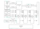
图4为本发明的控制系统原理框图。Fig. 4 is a functional block diagram of the control system of the present invention.
图5为本发明的震动场坐标变换流程图。Fig. 5 is a flow chart of the vibration field coordinate transformation of the present invention.
图6为本发明的无源定位方法流程图Fig. 6 is a flow chart of the passive positioning method of the present invention
图中:底壳1、顶壳2、安装螺口3、灌封材料4、、外部接口5、半球壳状压电陶瓷6、粘接层7、金属电极8、电源及信号调理电路板9、传感器与姿态测试电路板10、控制电路板11、铜柱12、Z轴标定安装孔13、X轴标定安装孔14、Y轴标定安装孔15、电路板安装孔16、用于姿态测试的三轴磁阻传感器17、用于姿态测试的三轴加速度传感器18、用于震动测试的低量程三轴加速度传感器19、用于震动测试的高量程三轴加速度传感器20、微控制器21、串口通信单元22、适配放大器23、抗混叠滤波器24、电压跟随器25、电荷放大器26、电源模块27。In the figure: bottom shell 1, top shell 2, mounting screw 3, potting material 4,
具体实施方式Detailed ways
以下结合附图详细说明本发明的技术方案。The technical solution of the present invention will be described in detail below in conjunction with the accompanying drawings.
一、一种复合式智能震动传感器1. A compound intelligent vibration sensor
一种复合式智能震动传感器,由球形结构和智能控制系统两部分组成。A composite intelligent vibration sensor is composed of two parts, a spherical structure and an intelligent control system.
1、球形安装结构1. Spherical mounting structure
图1与图2所示,球形结构包括:底壳1、顶壳2、安装螺口3、灌封材料4、外部接口5、半球状压电陶瓷6、粘接层7、金属电极8、电源及信号调理电路板9、传感器与姿态测试电路板10、控制电路板11、铜柱12、Z轴标定安装孔13、X轴标定安装孔14、Y轴标定安装孔15。As shown in Figure 1 and Figure 2, the spherical structure includes: bottom shell 1, top shell 2, mounting screw 3, potting material 4,
所述的底壳1、顶壳2通过安装螺口3连接,形成球形外壳。在顶壳2上部安装有外部接口5,用于与后续采集设备以及上位机连接。The bottom shell 1 and the top shell 2 are connected through the mounting screw 3 to form a spherical shell. An
所述的电源及信号调理电路板9、传感器与姿态测试电路板10、控制电路板11从上至下通过电路板安装孔16用铜柱12固定,底壳1和顶壳2内部的球形空腔填充有灌封材料4,通过现有灌封工艺以及模具技术,将上述电路板固定于空腔内,并保持传感器与姿态测试电路板10位于球形结构的中间平面,使电路板、灌封材料与外壳组成一体化的刚性结构。The power supply and signal conditioning circuit board 9, sensor and attitude testing circuit board 10, and control circuit board 11 are fixed with copper pillars 12 through circuit board mounting holes 16 from top to bottom, and the spherical hollow inside bottom shell 1 and top shell 2 The cavity is filled with potting material 4, and the above-mentioned circuit board is fixed in the cavity through the existing potting process and mold technology, and the sensor and attitude test circuit board 10 are kept in the middle plane of the spherical structure, so that the circuit board, potting The material and the shell form an integrated rigid structure.
所述的灌封材料是与土壤密度相匹配的低密度复合材料(如玻璃微珠与环氧树脂按一定比例的混合物),所述的顶壳和底壳是与土壤密度相匹配的复合材料或者非磁性金属合金。由于内部电路板及片上元器件的体积、质量远小于腔体内的灌封材料。因此,由电路板、灌封材料组成的腔体可以认为是由单一灌封材料组成的,这样由外壳、灌封材料和内部加速度传感器组成的多轴震动传感器的整体密度与土壤密度近似匹配。The potting material is a low-density composite material that matches the soil density (such as a mixture of glass microspheres and epoxy resin in a certain proportion), and the top shell and bottom shell are composite materials that match the soil density or non-magnetic metal alloys. Because the volume and quality of the internal circuit board and on-chip components are much smaller than the potting material in the cavity. Therefore, the cavity composed of the circuit board and potting material can be considered to be composed of a single potting material, so that the overall density of the multi-axis vibration sensor composed of the shell, potting material and internal acceleration sensor approximately matches the soil density.
本发明制成的实物是直径为5cm的球体,当在黏土这一背景下,平均土场参数如下:纵波传播速度为2000m/s,极限震动频率为6kHz时,传感器的波长小于震动信号波长的六分之一。根据相关声学理论:当传感器波长小于震动信号波长的六分之一,同时传感器整体密度与土壤密度近似相等时,震动传感器可以视为震动场中的一个质点,震动传感器的振动幅度、方向与震动信号传播到该质点的振动幅度、方向相同,相位差趋于零。当震动源近场产生的是应力波或冲击波等高频响震动信号时,传感器不能视为质点,在这种情况下,由于整个传感器采用球形设计,密度与土体匹配,加速度传信号处入球形结构的中心,能够最大程度的避免应力波在传感器结构内部出现折射、反射等现象,有效获取波到达的方向信息,提高DOA定位的精度。The actual object made by the present invention is a sphere with a diameter of 5cm. Under the background of clay, the average soil field parameters are as follows: the longitudinal wave propagation velocity is 2000m/s, and when the limit vibration frequency is 6kHz, the wavelength of the sensor is less than the wavelength of the vibration signal. one-sixth. According to the relevant acoustic theory: when the wavelength of the sensor is less than one-sixth of the wavelength of the vibration signal, and the overall density of the sensor is approximately equal to the density of the soil, the vibration sensor can be regarded as a particle in the vibration field, and the vibration amplitude, direction and vibration of the vibration sensor The vibration amplitude and direction of the signal propagating to the particle are the same, and the phase difference tends to zero. When the near-field of the vibration source produces high-frequency vibration signals such as stress waves or shock waves, the sensor cannot be regarded as a particle. The center of the spherical structure can avoid the refraction and reflection of the stress wave inside the sensor structure to the greatest extent, effectively obtain the direction information of the wave arrival, and improve the accuracy of DOA positioning.
所述的底壳1与顶壳2外部装有半球状压电陶瓷6,半球状压电陶瓷6的两面镀有金属电极8,半球状压电陶瓷6通过粘接层7(如环氧树脂)固定于底壳1、顶壳2表面,通过胶合剂将两个半球粘结成整球。上下两边的半球状压电陶瓷6两极并联,并将信号引入壳内的电源与信号调理电路上。The bottom shell 1 and the top shell 2 are equipped with hemispherical
图3所示,为标定安装孔、高、低量程加速度传感器、姿态测试模块之间的安装布局示意图。用于震动测试的低量程三轴加速度传感器19、用于震动测试的高量程三轴加速度传感器20是实现波到达的方向信息即矢量信息的关键,但所述的用于震动测试的低量程三轴加速度传感器19、用于震动测试的高量程三轴加速度传感器20外部存在由压电陶瓷、外壳和灌封材料组成的传递系统,其特性会随着传递系统的变化而发生变化。通过有限元对所述的压电陶瓷、外壳、灌封材料和加速度传感器组成的一体化结构进行模态分析,在分析时采用自由划分网格技术对模型进行网格划分,网格单元采用C3D10M(即修正的四面体二次缩减积分单元),通过中轴算法仿真,得出这种复合结构的频响能达到17kHz以上,满足震动信号频率的范围。同时通过现有灌封工艺,可以保证本发明的抗过载大于几万g,即可以在近场探测高强度的冲击信号。As shown in Figure 3, it is a schematic diagram of the installation layout among the calibration installation hole, the high and low range acceleration sensors, and the attitude test module. The low-range three-
其中,低量程加速度传感器、三轴磁阻传感器、三轴加速度传感器布局在传感器与姿态测试电路板的上面板上,高量程加速度传感器位于传感器与姿态测试电路板的下面板上。所述的低量程加速度传感器安装于电路板的中心,用于有效检测震动幅度小、频率响应低的爆破震动信号,高量程加速度传感器安装于低量程加速度传感器的正背面,用于有效检测震动幅度高、频率响应宽的震动信号。Among them, the low-range acceleration sensor, three-axis magnetoresistive sensor, and three-axis acceleration sensor are arranged on the upper panel of the sensor and attitude test circuit board, and the high-range acceleration sensor is located on the lower panel of the sensor and attitude test circuit board. The low-range acceleration sensor is installed in the center of the circuit board for effectively detecting blasting vibration signals with small vibration amplitude and low frequency response, and the high-range acceleration sensor is installed on the front and back of the low-range acceleration sensor for effective detection of vibration amplitude High vibration signal with wide frequency response.
所述的三轴磁阻传感器、三轴加速度传感器位于低量程加速度传感器X轴延长线上,三轴磁阻传感器的X轴、三轴加速度传感器的X轴与低量程加速度传感器X轴、高量程加速度传感器X轴位于同一轴线上,并且所有传感器的Y轴、Z轴都相互平行。The three-axis magnetoresistive sensor and the three-axis acceleration sensor are located on the X-axis extension line of the low-range acceleration sensor, the X-axis of the three-axis magnetoresistive sensor, the X-axis of the three-axis acceleration sensor and the X-axis and high-range The X axes of the acceleration sensors are on the same axis, and the Y axes and Z axes of all the sensors are parallel to each other.
所述的X轴标定安装孔、Y轴标定安装孔位于高低量程加速度传感器X、Y轴延长线与顶壳、底壳交界面的相交处。Z轴标定安装孔位于高低量程加速度传感器Z轴与底壳的相交处。The X-axis calibration mounting hole and the Y-axis calibration mounting hole are located at the intersection of the X-axis and Y-axis extension lines of the high and low range acceleration sensor and the interface between the top shell and the bottom shell. The Z-axis calibration mounting hole is located at the intersection of the Z-axis of the high and low range acceleration sensor and the bottom case.
所述的X轴标定安装孔14、Y轴标定安装孔15和Z轴标定安装孔13、用于对本发明进行动静态性能测试时,与标定设备刚性连接。The X-axis
2、智能控制系统2. Intelligent control system
图4所示,为智能控制系统的系统框图,智能控制系统包括:用于姿态测试的三轴磁阻传感器17、用于姿态测试的三轴加速度传感器18、用于震动测试的低量程三轴加速度传感器19、用于震动测试的高量程三轴加速度传感器20、微控制器21、串口通信单元22、适配放大器23、抗混叠滤波器24、电压跟随器25、电荷放大器26、电源模块27。As shown in Fig. 4, it is a system block diagram of an intelligent control system. The intelligent control system includes: a three-axis magnetoresistive sensor 17 for attitude testing, a three-
所述的用于姿态测试的三轴磁阻传感器17、用于姿态测试的三轴加速度传感器18经微控制器、串口通信单元与外部接口连接;所述的用于震动测试的高、低量程加速度传感器经适配放大器、抗混叠滤波器、电压跟随器与外部接口连接。所述的压电陶瓷经电荷放大器、适配放大器、抗混叠滤波器、电压跟随器与外部接口连接。所述的电源模块为三轴磁阻传感器、三轴加速度传感器、用于爆破震动测试的低量程三轴加速度传感器、用于爆破震动测试的高量程三轴加速度传感器、电荷放大器、适配放大器、抗混叠滤波器、电压跟随器、微控制器、串口通信单元提供电源。The described three-axis magnetoresistive sensor 17 for attitude test, the three-
所述的用于姿态测试的三轴磁阻传感器采用Honeywell公司的数字输出的三轴磁阻传感器HMC5883L,通过IIC总线与微控制器连接,用于检测高、低量程加速度传感器X轴偏离磁北的夹角(方位角)。所述的用于姿态测试的三轴加速度传感器采用ADI公司的数字输出的三轴加速度传感器ADXL345,通过IIC总线与微控制器连接,一方面,用于检测高、低量程加速度传感器偏离震动场坐标系下水平面的夹角(俯仰角、滚转角);另一方面,当高、低量程加速度传感器,安装在地下非水平状态时,补偿磁阻传感器三轴分量,提高磁阻传感器检测精度。The three-axis magnetoresistive sensor used for attitude testing adopts the three-axis magnetoresistive sensor HMC5883L of Honeywell Company's digital output, which is connected with the microcontroller through the IIC bus, and is used to detect whether the X-axis of the high-range and low-range acceleration sensors deviates from magnetic north. Angle (Azimuth). The three-axis acceleration sensor ADXL345 for the attitude test adopts the three-axis acceleration sensor ADXL345 of ADI Company's digital output, and is connected with the microcontroller through the IIC bus. The included angle (pitch angle, roll angle) of the lower horizontal plane; on the other hand, when the high-range and low-range acceleration sensors are installed underground in a non-horizontal state, the three-axis component of the magnetoresistive sensor is compensated to improve the detection accuracy of the magnetoresistive sensor.
所述的微控制器采用TI公司的MSP430F149,这是一款具有超低功耗的微控制器,可以使本发明的功耗降至最低。一方面,用于配置三轴磁阻传感器和三轴加速度传感器;另一方面,通过IIC总线,读取三轴磁阻传感器和三轴加速度传感器检测到的地磁信息和重力加速度信息,并通过内部运算,将地磁信息装换为方位角,将重力加速度信息转换为滚转角、俯仰角,并通过串口通信单元,将方位角、滚转角、俯仰角信息发送给地上控制部分。The microcontroller adopts MSP430F149 of TI Company, which is a microcontroller with ultra-low power consumption, which can minimize the power consumption of the present invention. On the one hand, it is used to configure the three-axis magnetoresistive sensor and the three-axis acceleration sensor; on the other hand, through the IIC bus, read the geomagnetic information and gravitational acceleration information detected by the three-axis magnetoresistive sensor and the three-axis acceleration sensor, and pass the internal Operation, convert the geomagnetic information into azimuth, convert the gravitational acceleration information into roll angle and pitch angle, and send the azimuth, roll angle, and pitch angle information to the ground control part through the serial port communication unit.
所述的低量程三轴加速度传感器采用ST公司模拟信号输出的三轴加速度传感器LIS344ALH,用于检测爆破震动测试过程中,低频响,低振幅的爆破震动信号。所述的高量程三轴加速度传感器采用Measurement公司模拟信号输出的三轴加速度传感器Model832M1,用于检测爆破震动测试过程中,高频响、大振幅的爆破震动信号。The low-range three-axis acceleration sensor adopts the three-axis acceleration sensor LIS344ALH with analog signal output by ST Company, which is used to detect blasting vibration signals with low frequency response and low amplitude during the blasting vibration test process. The high-range three-axis acceleration sensor adopts the three-axis acceleration sensor Model832M1 with analog signal output from Measurement Company, which is used to detect blasting vibration signals with high frequency response and large amplitude during the blasting vibration test process.
所述的适配放大器、抗混叠滤波器和电压跟随器用于将高、低量程加速度传感器输出的电压范围、阻抗值满足用户的要求。The adaptation amplifier, anti-aliasing filter and voltage follower are used to make the output voltage range and impedance value of the high-range and low-range acceleration sensors meet the user's requirements.
所述的电荷放大器采用运算放大器搭建,将压电陶瓷输出的电荷量转为电压量,由于此时输出的电压信号比较微弱,通过适配放大器,提高其信噪比。通过抗混叠滤波器和电压跟随器将压电陶瓷输出的信号满足用户的要求。The charge amplifier is built with an operational amplifier, which converts the charge output by the piezoelectric ceramic into a voltage. Since the output voltage signal is relatively weak at this time, the signal-to-noise ratio is improved by adapting the amplifier. Through the anti-aliasing filter and voltage follower, the output signal of the piezoelectric ceramic meets the user's requirements.
外部接口为复用接口,传感器在地下安装完成后,地上控制部分经过地上到地下的传输电缆线,利用RS485总线,读取方位角、滚转角和俯仰角,同时为传感器提供电源;在爆破震动测试过程中,地上控制部分通过所述的传输电缆线对高、低量程加速度传感器及压电陶瓷探测到的爆破震动信号进行采集。The external interface is a multiplex interface. After the sensor is installed underground, the ground control part passes through the transmission cable from the ground to the ground, and uses the RS485 bus to read the azimuth, roll angle and pitch angle, and provide power for the sensor at the same time; During the test, the ground control part collects the blasting vibration signals detected by the high- and low-range acceleration sensors and piezoelectric ceramics through the transmission cables.
二、使用复合式智能震动传感器的震源测试定位方法2. The source test and positioning method using the composite intelligent vibration sensor
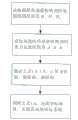
震源测试定位方法采用该震动传感器实现震源定位,围绕震源布置多个检测点,即检测点又称为震动探测节点,由地上控制部分和地下震动传感器组成。将该复合式震动传感器埋设在地下,每个检测点的震动传感器轴向上都有磁阻传感器和加速度传感器,分别用于检测震动传感器敏感轴偏离磁北方向和重力方向的夹角。在震源产生震动信号时,多个复合式智能震动传感器同时获取信号,通过获取的信号以及所述的夹角信息实现震源定位。基于本发明的震源定位方法具体流程如图6所示,主要包括三部分。The seismic source testing and positioning method adopts the vibration sensor to realize the positioning of the seismic source, and arranges a plurality of detection points around the seismic source, that is, the detection point is also called a vibration detection node, which is composed of an above-ground control part and an underground vibration sensor. The composite vibration sensor is buried underground, and the vibration sensor at each detection point has a magnetoresistive sensor and an acceleration sensor in the axial direction, which are used to detect the angle between the sensitive axis of the vibration sensor and the magnetic north direction and the gravity direction. When the seismic source generates a vibration signal, multiple composite intelligent vibration sensors acquire the signal at the same time, and realize the positioning of the seismic source through the acquired signal and the included angle information. The specific process of the seismic source location method based on the present invention is shown in Fig. 6, which mainly includes three parts.
1、基于TDOA的震源定位1. Seismic source location based on TDOA
将本发明压电陶瓷部分获取的压力-时间信号进行小波阈值去噪,去除有效信号中夹杂的噪声,以其中一个检测点作为参考点,将其余检测点获取的压力-时间信号与参考检测点获取的压力-时间信号进行基于相关分析或自适应滤波的时差测量LMS,得到时间差信息,通过现有的基于时间差的目标定位算法确定震源位置(x1,y1,z1)。其中目标算法:如传统的chan+taylor算法或基于粒子群的目标定位算法等。The pressure-time signal obtained by the piezoelectric ceramic part of the present invention is subjected to wavelet threshold denoising to remove the noise mixed in the effective signal, and one of the detection points is used as a reference point, and the pressure-time signal obtained by the remaining detection points is compared with the reference detection point The obtained pressure-time signal is subjected to time difference measurement LMS based on correlation analysis or adaptive filtering to obtain time difference information, and the source position (x1 , y1 , z1 ) is determined by the existing target location algorithm based on time difference. Among them, the target algorithm: such as the traditional chan+taylor algorithm or the target positioning algorithm based on particle swarm.
2、基于DOA的震源定位2. Seismic source location based on DOA
(1)获取各节点探测到的震动信号初至波的加速度峰值(1) Obtain the acceleration peak value of the first arrival wave of the vibration signal detected by each node
将所述的用于震动测试的高、低量程三轴加速度传感器获取的加速度信号进行基于HHT的信号去噪,通过能量比法,获取震动信号初至波的加速度峰值。设其中第i个传感器的高量程加速度传感器对应的加速度峰值为(ahix,ahiy,ahiz),低量程加速度传感器对应的加速度峰值为(alix,aliy,aliz),若第i个高量程加速度传感器探测到的震动信号加速度峰值大于低量程加速度传感器的探测范围,则震动信号初至波的加速度峰值(aix,aiy,aiz)=(ahix,ahiy,ahiz)即采用高量程探测到的加速度峰值进行下一步DOA定位;若高量程加速度传感器探测到的震动信号加速度峰值小于或等于低量程加速度传感器的探测范围,即将(ahix,ahiy,ahiz)和(alix,aliy,aliz)进行数据融合(如加权平均算法),得到震动信号初至波的三轴加速度峰值(aix,aiy,aiz)。The acceleration signals obtained by the high-range and low-range triaxial acceleration sensors used for the vibration test are subjected to HHT-based signal denoising, and the acceleration peak value of the first arrival wave of the vibration signal is obtained through the energy ratio method. Assume that the peak value of acceleration corresponding to the high-range acceleration sensor of the i-th sensor is (ahix , ahiy , ahiz ), and the peak value of acceleration corresponding to the low-range acceleration sensor is (alix , aliy , aliz ), if the i-th The peak acceleration of the vibration signal detected by a high-range acceleration sensor is greater than the detection range of the low-range acceleration sensor, then the peak acceleration of the first wave of the vibration signal (aix ,aiy ,aiz )=(ahix ,ahiy ,ahiz ) means to use the acceleration peak value detected by the high-range acceleration sensor for the next DOA positioning; if the acceleration peak value of the vibration signal detected by the high-range acceleration sensor is less than or equal to the detection range of the low-range acceleration sensor, then (ahix , ahiy , ahiz ) and (alix , aliy , aliz ) for data fusion (such as weighted average algorithm), to obtain the peak triaxial acceleration (aix , aiy , aiz ) of the first wave of the shock signal.
(2)传感器节点自身坐标系与震动场坐标系的转换(2) Transformation of the sensor node's own coordinate system and the vibration field coordinate system
坐标系进行转换是采用磁北方向和重力加速度方向组成的笛卡尔坐标系,并作为震动场的统一坐标系,通过复合式旋转矩阵算法,将各节点在自身坐标系下探测到的爆破震动信号初至波的加速度峰值信息转换成震动场的统一坐标系下的加速度峰值信息。The coordinate system conversion is to use the Cartesian coordinate system composed of the magnetic north direction and the gravitational acceleration direction as the unified coordinate system of the vibration field. Through the compound rotation matrix algorithm, the blasting vibration signal detected by each node in its own coordinate system is initially The acceleration peak information of the arrival wave is converted into the acceleration peak information in the unified coordinate system of the vibration field.
在地下震源定位过程中,每个传感器节点都通过深孔安装于地下,由于距地有一定的高度,人为无法将各个传感器节点内部的三轴自身坐标系都统一到一个坐标系下,因此,在震源定位过程中,无法通过各节点获取得波到达的方向信息,直接实现DOA定位,针对这一问题,本发明提出一种传感器节点自身坐标系与震动场坐标系的转换方法。In the process of underground seismic source positioning, each sensor node is installed underground through a deep hole. Due to a certain height from the ground, it is artificially impossible to unify the three-axis self-coordinate system inside each sensor node into one coordinate system. Therefore, In the process of seismic source positioning, it is impossible to obtain the direction information of wave arrival through each node and directly realize DOA positioning. To solve this problem, the present invention proposes a conversion method between the sensor node's own coordinate system and the vibration field coordinate system.
在震动测试场中,每个传感器节点都会受到地磁场和重力加速度的影响,在一定的区域范围内,地磁场的磁场强度和重力加速度的大小、方向可以近似恒定不变,因此设定震动场为笛卡尔坐标系,以磁北方向作为X轴、在大地水平面内与磁北相垂直的方向作为Y轴、地球重力方向作为Z轴。In the vibration test field, each sensor node will be affected by the geomagnetic field and the acceleration of gravity. Within a certain area, the magnetic field strength of the geomagnetic field and the magnitude and direction of the acceleration of gravity can be approximately constant. Therefore, the vibration field is set It is a Cartesian coordinate system, with the magnetic north direction as the X-axis, the direction perpendicular to magnetic north in the geodetic plane as the Y-axis, and the earth's gravity direction as the Z-axis.
各个震动传感器节点上安装有三轴加速度传感器和三轴地磁传感器,所述的三轴加速度传感器用于检测重力加速度在其三个轴向上的加速度分量设为AX、AY、AZ,并通过现有算法公式(1.1)(1.2)即可得出三轴加速度传感器X轴偏离大地水平面的垂直夹角


HY'=HY cosθ+HZ sinθ (1.4)HY '=HY cosθ+HZ sinθ (1.4)
γ=arctan(HY'/HX′) (1.5)γ=arctan(HY '/HX ′) (1.5)
三轴地磁传感器、三轴加速度传感器和用于震动测试的高、低量程加速度传感器的安装位置如图3所示,所述的三轴磁阻传感器、三轴加速度传感器位于低量程加速度传感器X轴延长线上,三轴磁阻传感器的X轴、三轴加速度传感器的X轴与低量程加速度传感器X轴、高量程加速度传感器X轴位于同一轴线上,并且所有传感器的Y轴、Z轴都相互平行。由所述的安装位置示意图可得,利用地磁传感器计算得到的方位角,即为所述的高、低量程加速度传感器X轴偏离震动场X轴的水平夹角;利用加速度传感器计算得到的俯仰角即为所述的高、低量程加速度传感器X轴偏离震动场X轴的垂直夹角;计算得到的滚转角即为所述的高、低量程加速度传感器Y轴偏离震动场Y轴的垂直夹角。The installation positions of the three-axis geomagnetic sensor, the three-axis acceleration sensor and the high and low range acceleration sensors used for vibration testing are shown in Figure 3. The three-axis magnetoresistive sensor and the three-axis acceleration sensor are located on the X-axis of the low-range acceleration sensor On the extension line, the X-axis of the three-axis magnetoresistive sensor, the X-axis of the three-axis acceleration sensor, the X-axis of the low-range acceleration sensor, and the X-axis of the high-range acceleration sensor are located on the same axis, and the Y-axis and Z-axis of all sensors are mutually parallel. It can be obtained from the schematic diagram of the installation position that the azimuth angle calculated by the geomagnetic sensor is the horizontal angle at which the X-axis of the high-range and low-range acceleration sensors deviates from the X-axis of the vibration field; the pitch angle calculated by the acceleration sensor That is, the vertical angle between the X-axis of the high-range and low-range acceleration sensors deviating from the X-axis of the vibration field; the calculated roll angle is the vertical angle between the Y-axis of the high-range and low-range acceleration sensors deviating from the Y-axis of the vibration field .
以第i个传感器为例,设(aix,aiy,aiz)为第i个传感器在地下安装完成后,在自身坐标系下,探测到爆破震动信号初至波的加速度分量;(aix′,aiy′,aiz′)为第i个传感器在震动场统一坐标系下,探测到爆破震动信号初至波的加速度分量。利用所述的俯仰角

(3)基于DOA定位算法(3) Based on DOA positioning algorithm
在震动场统一坐标系下,将上述各节点探测到的爆破震动信号初至波的加速度分量转换为各节点相对于震源的方位角和俯仰角,并利用现有的DOA多点测向交叉定位算法(如基于牛顿迭代的最小二乘交叉定位法),实现震源定位(x2,y2,z2)。In the unified coordinate system of the shock field, the acceleration component of the first arrival wave of the blasting vibration signal detected by each node above is converted into the azimuth and elevation angle of each node relative to the seismic source, and the existing DOA multi-point direction finding is used for cross positioning Algorithms (such as least squares cross-location method based on Newton iteration) to realize source location (x2 , y2 , z2 ).
3、定位结果数据融合3. Data fusion of positioning results
将TDOA定位结果(x1,y1,z1)和DOA定位结果(x2,y2,z2)进行数据融合。采用现有的融合算法(如基于泰勒序列展开式的混合定位或加权最小二乘融合算法),实现最终震源定位,得到震源位置(x,y,z)。其中:The TDOA positioning results (x1 , y1 , z1 ) and DOA positioning results (x2 , y2 , z2 ) are fused together. Use existing fusion algorithms (such as hybrid positioning based on Taylor sequence expansion or weighted least squares fusion algorithm) to achieve the final source location and obtain the source location (x, y, z). in:
TDOA为基于时间差定位法,主要是通过各传感器节点接收信号的时间延迟实现对目标源定位;TDOA is based on the time difference positioning method, which mainly realizes the positioning of the target source through the time delay of the signal received by each sensor node;
DOA为基于波到达方向定位法,主要是通过传感器节点接受信号时到达方向角的不同来实现对目标源的定位。DOA is based on the direction of arrival positioning method of waves, which mainly realizes the positioning of the target source through the difference in the direction of arrival angle when the sensor node receives the signal.
在传感器安装完成之后,利用地上控制系统,读取方位角、俯仰角和滚转角等姿态信息,在震动测试过程中,地上控制系统采集本发明高、低量程加速度传感器探测到的震动信号和压电陶瓷探测到的压力信息。在完成震动测试后,在上位机上,利用所述的高频响的压力-时间信息进行基于TDOA的震源定位,利用所述的姿态信息和震动加速度信息进行基于DOA的震源定位,并将两者的定位结果通过数据融合实现高精度的混合定位。本发明所述的复合式传感器配合所述的混合定位算法,可以实现煤层采空区监测、隧道空洞检测、靶场弹着点等多种震源定位,同时可以有效地研究应力波在震动测试场中的相关理论。在工程爆破、国防军事、环境监测、煤矿安全生产等领域有着非常广泛的应用前景。After the installation of the sensor is completed, the ground control system is used to read attitude information such as azimuth, pitch angle and roll angle. Pressure information detected by electroceramics. After completing the vibration test, on the host computer, use the high-frequency response pressure-time information to perform TDOA-based seismic source positioning, use the described attitude information and vibration acceleration information to perform DOA-based seismic source positioning, and combine the two The positioning results achieve high-precision hybrid positioning through data fusion. The composite sensor of the present invention cooperates with the hybrid positioning algorithm, which can realize multiple seismic source positioning such as coal seam goaf monitoring, tunnel cavity detection, shooting range impact point, etc., and can effectively study the correlation of stress waves in the vibration test field. theory. It has a very broad application prospect in engineering blasting, national defense and military, environmental monitoring, coal mine safety production and other fields.
Claims (5)
Translated fromChinesePriority Applications (1)
| Application Number | Priority Date | Filing Date | Title |
|---|---|---|---|
| CN201210353274.XACN102841371B (en) | 2012-09-20 | 2012-09-20 | Compound intelligent vibration sensor and vibration source test and location method |
Applications Claiming Priority (1)
| Application Number | Priority Date | Filing Date | Title |
|---|---|---|---|
| CN201210353274.XACN102841371B (en) | 2012-09-20 | 2012-09-20 | Compound intelligent vibration sensor and vibration source test and location method |
Publications (2)
| Publication Number | Publication Date |
|---|---|
| CN102841371Atrue CN102841371A (en) | 2012-12-26 |
| CN102841371B CN102841371B (en) | 2015-03-25 |
Family
ID=47368904
Family Applications (1)
| Application Number | Title | Priority Date | Filing Date |
|---|---|---|---|
| CN201210353274.XAExpired - Fee RelatedCN102841371B (en) | 2012-09-20 | 2012-09-20 | Compound intelligent vibration sensor and vibration source test and location method |
Country Status (1)
| Country | Link |
|---|---|
| CN (1) | CN102841371B (en) |
Cited By (24)
| Publication number | Priority date | Publication date | Assignee | Title |
|---|---|---|---|---|
| CN105160821A (en)* | 2015-08-03 | 2015-12-16 | 福建星网锐捷通讯股份有限公司 | Earthquake alarming method of building intercom system and building intercom system |
| CN105403192A (en)* | 2015-12-17 | 2016-03-16 | 中国地震局地壳应力研究所 | Ball-type random-orientation deformation measurement instrument |
| CN105606141A (en)* | 2016-02-29 | 2016-05-25 | 汉得利(常州)电子股份有限公司 | Omnibearing spherical ultrasonic sensor |
| CN106646378A (en)* | 2017-01-03 | 2017-05-10 | 中北大学 | Method for determining underground excavation position |
| CN106706107A (en)* | 2017-03-30 | 2017-05-24 | 中国环境监测总站 | Deep vibration testing signal collector and deep vibration testing device |
| CN106768759A (en)* | 2016-12-21 | 2017-05-31 | 江苏安纳金机械有限公司 | Vibration test positioning tool |
| CN106839967A (en)* | 2017-04-10 | 2017-06-13 | 中国有色金属工业昆明勘察设计研究院 | Spherical ess-strain monitoring device that is a kind of multi-direction and can combining |
| CN107561590A (en)* | 2017-08-11 | 2018-01-09 | 武汉中岩科技有限公司 | A kind of soil layer shearing wave test device and its method |
| CN108592973A (en)* | 2018-07-23 | 2018-09-28 | 中国华能集团清洁能源技术研究院有限公司 | Casing and the equipment conveying vibration with it and attitude monitoring device |
| CN109798917A (en)* | 2018-12-19 | 2019-05-24 | 成佳颖 | A kind of positioning accuracy method for inspecting |
| CN109856371A (en)* | 2019-04-18 | 2019-06-07 | 宁波高新区阶梯科技有限公司 | A kind of soil testing assemblies |
| CN110414675A (en)* | 2019-09-02 | 2019-11-05 | 中北大学 | A Deep Learning-Based Method for Locating Shallow Underground Seismic Sources |
| CN110737017A (en)* | 2019-10-18 | 2020-01-31 | 钱荣毅 | Advanced forecasting and collecting device for coal roadways |
| CN111736109A (en)* | 2020-07-01 | 2020-10-02 | 易思维(天津)科技有限公司 | Indoor positioning system receiver and method for evaluating precision by using same |
| CN112051611A (en)* | 2020-09-07 | 2020-12-08 | 中北大学 | Deep reinforcement learning-based method for localization of subsurface initiation points |
| CN112857468A (en)* | 2021-03-10 | 2021-05-28 | 中国科学院宁波材料技术与工程研究所 | Dual-mode sensor for measuring strain and magnetic field and preparation method thereof |
| CN112924932A (en)* | 2021-01-25 | 2021-06-08 | 吉林大学 | Vehicle positioning method and system based on grid search Newton iterative algorithm |
| CN112945362A (en)* | 2021-01-29 | 2021-06-11 | 长安大学 | Dynamic sensing device and measuring method for axle weight and vehicle speed |
| US11313745B2 (en)* | 2019-04-25 | 2022-04-26 | United States Of America As Represented By The Secretary Of The Air Force | Solid instrumented spherical blast impulse recording device (SISBIRD) |
| CN114514414A (en)* | 2019-10-31 | 2022-05-17 | Vega格里沙贝两合公司 | Measuring device for process automation in an industrial environment |
| CN114624761A (en)* | 2022-03-31 | 2022-06-14 | 辽宁工程技术大学 | A mine earthquake location method and device, and storage medium |
| US11378476B2 (en)* | 2019-04-22 | 2022-07-05 | United States Of America As Represented By The Secretary Of The Air Force | Instrumented spherical blast impulse recording device (ISBIRD) |
| CN115046578A (en)* | 2021-04-15 | 2022-09-13 | 深圳中云创新技术有限公司 | Circuit structure integrating multiple sensing assemblies and terminal comprising circuit structure |
| CN116233780A (en)* | 2022-12-26 | 2023-06-06 | 郑州丰嘉科技有限公司 | Open-air intelligent historical relic monitored control system based on vibration sensor |
Citations (4)
| Publication number | Priority date | Publication date | Assignee | Title |
|---|---|---|---|---|
| JPH0933250A (en)* | 1995-07-24 | 1997-02-07 | Tokyu Constr Co Ltd | Method and apparatus for measuring discontinuous plane of geology |
| CN101436046A (en)* | 2008-12-08 | 2009-05-20 | 东南大学 | Integrated multichannel synchronous oscillation data acquiring and monitoring and analysis diagnostic device |
| US20120089373A1 (en)* | 2010-10-07 | 2012-04-12 | Electronics And Telecommuincations Research Institute | Apparatus and method for controlling sensor node using vibration sensor and magnetic sensor |
| WO2012039681A8 (en)* | 2010-09-22 | 2012-05-24 | National University Of Singapore | Vibration detector and method |
- 2012
- 2012-09-20CNCN201210353274.XApatent/CN102841371B/ennot_activeExpired - Fee Related
Patent Citations (4)
| Publication number | Priority date | Publication date | Assignee | Title |
|---|---|---|---|---|
| JPH0933250A (en)* | 1995-07-24 | 1997-02-07 | Tokyu Constr Co Ltd | Method and apparatus for measuring discontinuous plane of geology |
| CN101436046A (en)* | 2008-12-08 | 2009-05-20 | 东南大学 | Integrated multichannel synchronous oscillation data acquiring and monitoring and analysis diagnostic device |
| WO2012039681A8 (en)* | 2010-09-22 | 2012-05-24 | National University Of Singapore | Vibration detector and method |
| US20120089373A1 (en)* | 2010-10-07 | 2012-04-12 | Electronics And Telecommuincations Research Institute | Apparatus and method for controlling sensor node using vibration sensor and magnetic sensor |
Non-Patent Citations (2)
| Title |
|---|
| 乔梁: "基于TDOA和DOA测量的单站无源定位方法研究", 《沈阳工程学院学报(自然科学版)》* |
| 郭华: "TDOA定位技术的基本原理和算法", 《西安邮电学院学报》* |
Cited By (29)
| Publication number | Priority date | Publication date | Assignee | Title |
|---|---|---|---|---|
| CN105160821A (en)* | 2015-08-03 | 2015-12-16 | 福建星网锐捷通讯股份有限公司 | Earthquake alarming method of building intercom system and building intercom system |
| CN105403192B (en)* | 2015-12-17 | 2019-04-09 | 中国地震局地壳应力研究所 | A kind of ball-type is arbitrarily to earth deformation measurement instrument |
| CN105403192A (en)* | 2015-12-17 | 2016-03-16 | 中国地震局地壳应力研究所 | Ball-type random-orientation deformation measurement instrument |
| CN105606141A (en)* | 2016-02-29 | 2016-05-25 | 汉得利(常州)电子股份有限公司 | Omnibearing spherical ultrasonic sensor |
| CN106768759A (en)* | 2016-12-21 | 2017-05-31 | 江苏安纳金机械有限公司 | Vibration test positioning tool |
| CN106646378A (en)* | 2017-01-03 | 2017-05-10 | 中北大学 | Method for determining underground excavation position |
| CN106706107A (en)* | 2017-03-30 | 2017-05-24 | 中国环境监测总站 | Deep vibration testing signal collector and deep vibration testing device |
| CN106839967A (en)* | 2017-04-10 | 2017-06-13 | 中国有色金属工业昆明勘察设计研究院 | Spherical ess-strain monitoring device that is a kind of multi-direction and can combining |
| CN107561590A (en)* | 2017-08-11 | 2018-01-09 | 武汉中岩科技有限公司 | A kind of soil layer shearing wave test device and its method |
| CN108592973A (en)* | 2018-07-23 | 2018-09-28 | 中国华能集团清洁能源技术研究院有限公司 | Casing and the equipment conveying vibration with it and attitude monitoring device |
| CN108592973B (en)* | 2018-07-23 | 2024-04-16 | 中国华能集团清洁能源技术研究院有限公司 | Casing and equipment transport vibration and attitude monitor having the same |
| CN109798917A (en)* | 2018-12-19 | 2019-05-24 | 成佳颖 | A kind of positioning accuracy method for inspecting |
| CN109856371A (en)* | 2019-04-18 | 2019-06-07 | 宁波高新区阶梯科技有限公司 | A kind of soil testing assemblies |
| US11378476B2 (en)* | 2019-04-22 | 2022-07-05 | United States Of America As Represented By The Secretary Of The Air Force | Instrumented spherical blast impulse recording device (ISBIRD) |
| US11313745B2 (en)* | 2019-04-25 | 2022-04-26 | United States Of America As Represented By The Secretary Of The Air Force | Solid instrumented spherical blast impulse recording device (SISBIRD) |
| CN110414675A (en)* | 2019-09-02 | 2019-11-05 | 中北大学 | A Deep Learning-Based Method for Locating Shallow Underground Seismic Sources |
| CN110414675B (en)* | 2019-09-02 | 2022-05-27 | 中北大学 | Underground shallow seismic source positioning method based on deep learning |
| CN110737017A (en)* | 2019-10-18 | 2020-01-31 | 钱荣毅 | Advanced forecasting and collecting device for coal roadways |
| CN110737017B (en)* | 2019-10-18 | 2021-10-22 | 钱荣毅 | Advanced forecasting and collecting device for coal roadway |
| CN114514414A (en)* | 2019-10-31 | 2022-05-17 | Vega格里沙贝两合公司 | Measuring device for process automation in an industrial environment |
| US12399043B2 (en) | 2019-10-31 | 2025-08-26 | Vega Grieshaber Kg | Measuring device for process automation in the industrial environment |
| CN111736109A (en)* | 2020-07-01 | 2020-10-02 | 易思维(天津)科技有限公司 | Indoor positioning system receiver and method for evaluating precision by using same |
| CN112051611A (en)* | 2020-09-07 | 2020-12-08 | 中北大学 | Deep reinforcement learning-based method for localization of subsurface initiation points |
| CN112924932A (en)* | 2021-01-25 | 2021-06-08 | 吉林大学 | Vehicle positioning method and system based on grid search Newton iterative algorithm |
| CN112945362A (en)* | 2021-01-29 | 2021-06-11 | 长安大学 | Dynamic sensing device and measuring method for axle weight and vehicle speed |
| CN112857468A (en)* | 2021-03-10 | 2021-05-28 | 中国科学院宁波材料技术与工程研究所 | Dual-mode sensor for measuring strain and magnetic field and preparation method thereof |
| CN115046578A (en)* | 2021-04-15 | 2022-09-13 | 深圳中云创新技术有限公司 | Circuit structure integrating multiple sensing assemblies and terminal comprising circuit structure |
| CN114624761A (en)* | 2022-03-31 | 2022-06-14 | 辽宁工程技术大学 | A mine earthquake location method and device, and storage medium |
| CN116233780A (en)* | 2022-12-26 | 2023-06-06 | 郑州丰嘉科技有限公司 | Open-air intelligent historical relic monitored control system based on vibration sensor |
Also Published As
| Publication number | Publication date |
|---|---|
| CN102841371B (en) | 2015-03-25 |
Similar Documents
| Publication | Publication Date | Title |
|---|---|---|
| CN102841371B (en) | Compound intelligent vibration sensor and vibration source test and location method | |
| CN103605151B (en) | Based on the Distributed Cluster ripple shallow-layer microseism localization method of phase measurement | |
| CN108431637B (en) | Multi-axis single-mass accelerometer | |
| AU2012334818B2 (en) | Vibration analysis for blasting | |
| CN109001829B (en) | Strapdown underwater dynamic gravity measuring instrument | |
| CN201280927Y (en) | Underground pipeline detecting and prewarning apparatus | |
| CN109490966A (en) | A kind of crustal magnetotelluric measurement system | |
| WO2012018118A1 (en) | False ore, and analysis system using same | |
| Scudero et al. | MEMS technology in seismology: A short review | |
| CN103513273B (en) | The land digital seismoreceivers of four components | |
| CN201397397Y (en) | Track detecting instrument of multi-parameter underground pipeline | |
| CN101750629A (en) | Differential positioning seismometer while drilling | |
| CN102628960B (en) | Velocity and acceleration two-parameter digital geophone | |
| Geng et al. | Design and fabrication of hollow mushroom-like cilia MEMS vector hydrophone | |
| CN107092018A (en) | Portable acoustic positioning system and localization method for dykes and dams waters | |
| CN1256597C (en) | Three-component digital seismic exploration wave detector | |
| CN113917549A (en) | Airborne electromagnetic data acquisition system and acquisition method based on optical fiber sensing technology | |
| CN108120439B (en) | A three-component induction coil attitude measurement method and device | |
| Ali Bakir et al. | Low Cost MEMS accelerograph: structure, operation and application to seismology | |
| CN207007874U (en) | Three-dimensional ultrasonic wind meter based on nonopiate survey wind formation | |
| CN210072106U (en) | Land multi-parameter physical data acquisition device | |
| CN104391320A (en) | MEMS (micro-electro-mechanical systems) omnidirectional vibration sensor | |
| CN103575383A (en) | Low-frequency multi-output passive servo vibration sensor capable of simultaneously measuring acceleration and velocity | |
| CN104111063B (en) | A kind of Wireless 3 D obliquity sensor based on magnetic field and detection method thereof | |
| CN102182449B (en) | Measuring device adopting solid-state vibration angular rate sensor group to realize north-seeking underground |
Legal Events
| Date | Code | Title | Description |
|---|---|---|---|
| C06 | Publication | ||
| PB01 | Publication | ||
| C10 | Entry into substantive examination | ||
| SE01 | Entry into force of request for substantive examination | ||
| C14 | Grant of patent or utility model | ||
| GR01 | Patent grant | ||
| CF01 | Termination of patent right due to non-payment of annual fee | Granted publication date:20150325 | |
| CF01 | Termination of patent right due to non-payment of annual fee |