CN102830793A - Sight tracking method and sight tracking device - Google Patents
Sight tracking method and sight tracking deviceDownload PDFInfo
- Publication number
- CN102830793A CN102830793ACN2011101672182ACN201110167218ACN102830793ACN 102830793 ACN102830793 ACN 102830793ACN 2011101672182 ACN2011101672182 ACN 2011101672182ACN 201110167218 ACN201110167218 ACN 201110167218ACN 102830793 ACN102830793 ACN 102830793A
- Authority
- CN
- China
- Prior art keywords
- eye
- pupil
- center
- dimensional coordinates
- mrow
- Prior art date
- Legal status (The legal status is an assumption and is not a legal conclusion. Google has not performed a legal analysis and makes no representation as to the accuracy of the status listed.)
- Granted
Links
Images


Landscapes
- Image Analysis (AREA)
- Image Processing (AREA)
Abstract
Translated fromChinese
Description
Translated fromChinese技术领域technical field
本发明涉及计算机视觉和图像处理技术,具体涉及一种视线跟踪方法和设备。The invention relates to computer vision and image processing technology, in particular to a line of sight tracking method and device.
背景技术Background technique
视线方向跟踪技术具有非常广泛的应用,如在认知科学、心理学、医学、残疾人辅助等领域。随着计算机技术的发展,视线跟踪技术还被用于人机交互、虚拟现实等方面。例如,一些研究工作尝试使用视线或视点检测装置作为计算机的输入接口,以获得更迅速的响应,在一定程度上取代鼠标和键盘。另外,通过获取观察者的视线,得到其感兴趣的位置,以进行网页、广告等的设计优化。Gaze direction tracking technology has a very wide range of applications, such as in cognitive science, psychology, medicine, assisting the disabled and other fields. With the development of computer technology, eye-tracking technology is also used in human-computer interaction, virtual reality and other aspects. For example, some research works try to use line-of-sight or point-of-view detection devices as the input interface of the computer to obtain faster response and replace the mouse and keyboard to a certain extent. In addition, by obtaining the viewer's line of sight, the position of interest is obtained, so as to optimize the design of web pages and advertisements.
使用不同的分类方法,视线跟踪技术可以被分为很多类别,如接触式、非接触式,光学方法、电子方法、基于穿着设备的方法和远距离跟踪等。下面介绍几种比较典型的视线跟踪方法或系统。Using different classification methods, gaze tracking technology can be divided into many categories, such as contact, non-contact, optical methods, electronic methods, wearable device-based methods, and long-distance tracking. Several typical gaze tracking methods or systems are introduced below.
最早的视线跟踪系统使用与眼球直接接触的器件,跟随眼球的运动。通过光学方法或者电磁传感器,得到其运动信息,也就得到了眼球的运动信息,经过校准,就可以获得视线方向。这类方法通常具有较高的灵敏性和精度,但由于采用侵入式获取信息的方式,用户使用非常不便,设备的价格较高。The earliest eye-tracking systems used devices that made direct contact with the eyeball, following the eye's movement. Through optical methods or electromagnetic sensors, the movement information of the eyeball is obtained, and the eyeball movement information is obtained. After calibration, the line of sight direction can be obtained. This type of method usually has high sensitivity and precision, but due to the intrusive way of obtaining information, it is very inconvenient for users to use, and the price of the equipment is relatively high.
另一种接触式检测方法基于眼球运动时眼部区域电势场变化的原理,在眼睛周围粘贴一些电子传感探头,测量电子信号的变化。与基于光学的方法相比,这种方法对使用环境的光照条件没有任何要求。Another contact detection method is based on the principle of changes in the electric potential field in the eye area during eye movements. Some electronic sensing probes are pasted around the eyes to measure the changes in electronic signals. Compared with optical-based methods, this method does not have any requirements on the lighting conditions of the use environment.
在基于光学观测的各种方法和系统中,最常用的手段是使用一个或多个近红外或可见光光源,以及一个或多个图像传感器,得到眼部图像,测量反光位置以及虹膜、瞳孔的几何参数来估计视线方向。眼球结构中,有多个可以产生反光的位置,如角膜内外表面,晶状体内外表面。另外,使用特殊设备,还可以直接捕获视网膜表面的图像,用于眼球运动和视线跟踪。使用光学观测的方法可以使传感器不与用户直接接触,使用比较方便,所以成为应用范围最广泛的一种方式。Among the various methods and systems based on optical observation, the most commonly used method is to use one or more near-infrared or visible light sources, and one or more image sensors to obtain eye images, measure the reflective position and the geometry of the iris and pupil. parameter to estimate the gaze direction. In the structure of the eyeball, there are multiple locations that can produce reflections, such as the inner and outer surfaces of the cornea, and the inner and outer surfaces of the lens. Alternatively, with special equipment, images of the retinal surface can be captured directly for eye movement and gaze tracking. The method of using optical observation can make the sensor not in direct contact with the user, and it is more convenient to use, so it has become the most widely used method.
视线方向可以看作头部方向与眼球方向的合成。如果使用固定在头部的跟踪方法和系统,为了得到视线方向,通常还需测量头部的运动。使用不依附于头部的远距离跟踪方法和系统,通常可以直接得到视线方向。在这类系统中,一部分要求用户的头部固定,另外一部分则允许用户的头部在一定范围内运动。The gaze direction can be regarded as the synthesis of the head direction and the eyeball direction. If head-fixed tracking methods and systems are used, in order to obtain the gaze direction, it is usually necessary to measure the movement of the head. Using long-distance tracking methods and systems that are not attached to the head, it is often possible to obtain the gaze direction directly. Among these systems, some require the user's head to be fixed, while others allow the user's head to move within a certain range.
大部分现有的技术依赖于专用设备,如电压传感器、红外光源、高分辨率摄像头、微距镜头、头戴固定装置等。在增加成本的同时,限制了这一技术的应用范围。在精度要求不十分严格的应用中,使用常见的普通分辨率摄像头实现视线方向跟踪,尤其是只使用一个摄像头实现视线方向跟踪,是非常必要的。在很多视线跟踪系统中,用户的头部被限制为不能移动,或者仅允许平移,不允许旋转,或者仅允许在很小的范围内旋转,或者不允许面部表情变化,这些都降低了用户使用的舒适性和跟踪系统的应用范围。部分技术只根据头部方位来确定视线方向,大大降低了精度。另外,大部分视线跟踪系统需要校准环节,降低了易用性。Most existing technologies rely on specialized equipment such as voltage sensors, infrared light sources, high-resolution cameras, macro lenses, head-mounted fixtures, etc. While increasing the cost, the application range of this technology is limited. In applications where accuracy requirements are not very strict, it is necessary to use a common ordinary resolution camera to track the line of sight, especially to use only one camera to track the line of sight. In many eye-tracking systems, the user's head is restricted from moving, or only allowed to translate, not allowed to rotate, or only allowed to rotate within a small range, or not allowed to change facial expressions, which all reduce the user's ability to use The comfort and application range of the tracking system. Some technologies determine the line of sight direction only based on the orientation of the head, which greatly reduces the accuracy. In addition, most eye-tracking systems require a calibration process, which reduces ease of use.
发明内容Contents of the invention
本发明的目的在于提供一种视线跟踪方法和设备,其能够仅使用一个摄像头捕获的视频图像就可实现对视线的跟踪。The object of the present invention is to provide a line of sight tracking method and device, which can realize line of sight tracking using only a video image captured by a camera.
本发明的目的还在于提供一种视线跟踪方法和设备,其能够在用户面部表情和/或头部姿态发生变化的情况下也可以实现对视线的跟踪。The object of the present invention is also to provide a gaze tracking method and device, which can realize gaze tracking even when the user's facial expression and/or head posture changes.
本发明的一方面在于提供一种视线跟踪方法,其特征在于包括:获取包含用户头部的图像作为输入图像;根据输入图像对面部关键点进行跟踪;根据跟踪到的面部关键点,对瞳孔中心和眼球中心进行定位,以确定瞳孔中心的三维坐标和眼球中心的三维坐标;使用瞳孔中心的三维坐标和眼球中心的三维坐标,计算用户的视线方向。One aspect of the present invention is to provide a line of sight tracking method, which is characterized in that it includes: acquiring an image containing the user's head as an input image; tracking facial key points according to the input image; tracking the pupil center according to the tracked facial key points Positioning with the eyeball center to determine the three-dimensional coordinates of the pupil center and the three-dimensional coordinates of the eyeball center; using the three-dimensional coordinates of the pupil center and the three-dimensional coordinates of the eyeball center to calculate the user's line of sight direction.
此外,对瞳孔中心进行定位的步骤可包括:根据面部关键点的二维坐标或三维坐标获得眼部纹理图像,并计算形状归一化的眼部纹理图像;从形状归一化的眼部纹理图像中检测实际瞳孔区域;根据实际瞳孔区域确定瞳孔中心的坐标,并通过对瞳孔中心的坐标进行逆形状归一化,来计算瞳孔中心在输入图像中的坐标,其中,通过将瞳孔中心在输入图像中的坐标映射到面部关键点的三维坐标所在的坐标系来获得瞳孔中心的三维坐标。In addition, the step of locating the pupil center may include: obtaining an eye texture image according to two-dimensional or three-dimensional coordinates of facial key points, and calculating a shape-normalized eye texture image; Detect the actual pupil area in the image; determine the coordinates of the pupil center according to the actual pupil area, and calculate the coordinates of the pupil center in the input image by performing inverse shape normalization on the coordinates of the pupil center, wherein, by putting the pupil center in the input The coordinates in the image are mapped to the coordinate system where the 3D coordinates of facial key points are located to obtain the 3D coordinates of the pupil center.
此外,计算形状归一化的眼部纹理图像的步骤可包括:将眼部纹理图像所覆盖的像素变换到规范化的纹理模板中,以获得形状归一化的眼部纹理图像,其中,通过将在眼部处于预定形状的条件下获得的眼部关键点投影到输入图像所在的平面上得到规范化的纹理模板。In addition, the step of calculating the shape-normalized eye texture image may include: transforming the pixels covered by the eye texture image into a normalized texture template to obtain a shape-normalized eye texture image, wherein, by The key points of the eye obtained under the condition that the eye is in a predetermined shape are projected onto the plane of the input image to obtain a normalized texture template.
此外,从形状归一化的眼部纹理图像中检测实际瞳孔区域的步骤可包括:从眼部纹理图像中检测多个瞳孔候选区域;从检测的多个瞳孔候选区域中选择瞳孔区域;根据瞳孔区域确定实际瞳孔区域。In addition, the step of detecting the actual pupil region from the shape-normalized eye texture image may include: detecting a plurality of pupil candidate regions from the eye texture image; selecting a pupil region from the detected plurality of pupil candidate regions; Region determines the actual pupil region.
此外,从眼部纹理图像中检测多个瞳孔候选区域的步骤可包括:使用窗口对眼部纹理图像进行扫描以获得多个窗口区域;使用下面的等式计算每个窗口区域的分数值In addition, the step of detecting a plurality of pupil candidate regions from the eye texture image may include: scanning the eye texture image using a window to obtain a plurality of window regions; calculating a score value for each window region using the following equation
其中,R表示窗口区域,ER表示窗口边缘区域,x表示像素坐标,I(x)为在像素坐标x处的像素的亮度,▽I(x)表示在像素坐标x处的亮度梯度,N为窗口区域内像素的个数,
此外,从检测的多个瞳孔候选区域中选择瞳孔区域的步骤可包括:根据左瞳孔候选区域在左眼的形状归一化的眼部纹理图像中的相对位置和右瞳孔候选区域在右眼的形状归一化的眼部纹理图像中的相对位置,从左瞳孔候选区域和右瞳孔候选区域中确定出一对左右瞳孔区域。In addition, the step of selecting the pupil region from the detected plurality of pupil candidate regions may include: according to the relative position of the left pupil candidate region in the shape-normalized eye texture image of the left eye and the right pupil candidate region in the right eye The relative positions in the shape-normalized eye texture image determine a pair of left and right pupil regions from the left pupil candidate region and the right pupil candidate region.
此外,从检测的多个瞳孔候选区域中选择瞳孔区域的步骤还可包括:从所有的左瞳孔候选区域与所有的右瞳孔候选区域的所有配对中,去除相对位置差别大于预定阈值的配对,从剩余的配对中选出分数值之和最小的一对左右瞳孔候选区域作为一对左右瞳孔区域。In addition, the step of selecting the pupil region from the detected plurality of pupil candidate regions may further include: from all pairs of all left pupil candidate regions and all right pupil candidate regions, removing pairs whose relative position difference is greater than a predetermined threshold, from A pair of left and right pupil candidate areas with the smallest sum of scores is selected from the remaining pairings as a pair of left and right pupil areas.
此外,眼部纹理图像可包括左眼的眼部纹理图像和右眼的眼部纹理图像,计算形状归一化的眼部纹理图像的步骤包括计算左眼的形状归一化的眼部纹理图像和右眼的形状归一化的眼部纹理图像,其中,通过将在眼部处于预定形状条件下的眼部关键点的三维坐标投影到一个平面上并连接映射到该平面上的关键点形成网格,来得到规范化的纹理模板。In addition, the eye texture image may include an eye texture image for the left eye and an eye texture image for the right eye, and the step of calculating the shape-normalized eye texture image includes calculating the shape-normalized eye texture image for the left eye and the shape-normalized eye texture image of the right eye, in which, the eye is formed by projecting the three-dimensional coordinates of the key points of the eye under the condition that the eye is in a predetermined shape onto a plane and connecting the key points mapped to the plane grid to get a normalized texture template.
此外,所述平面可以为由眼部关键点在空间中形成的眼部所正对或背对的一个平面。In addition, the plane may be a plane formed by the key points of the eyes in space, facing or facing away from the eyes.
此外,根据瞳孔区域确定实际瞳孔区域的步骤可包括:(a)根据当前的瞳孔区域中像素的亮度均值,设置大于等于亮度均值的拒绝阈值,并设置小于等于亮度均值的接受阈值;(b)确定在当前的瞳孔区域内部的与当前的瞳孔区域的边缘相邻的像素中是否存在亮度大于拒绝阈值的像素,并确定在当前的瞳孔区域外部的与当前瞳孔区域的边缘相邻的像素中是否存在亮度小于接受阈值的像素;(c)当存在亮度大于拒绝阈值的像素时,将亮度大于拒绝阈值的像素从当前的瞳孔区域移除;当存在亮度小于接受阈值的像素时,将亮度小于接受阈值的像素添加到当前的瞳孔区域中;(d)对当前的瞳孔区域的轮廓进行平滑,并进行操作(a);(e)当不存在亮度大于拒绝阈值的像素并且不存在亮度小于接受阈值的像素时,当前的瞳孔区域为实际瞳孔区域。In addition, the step of determining the actual pupil area according to the pupil area may include: (a) according to the average brightness value of pixels in the current pupil area, setting a rejection threshold greater than or equal to the average brightness value, and setting an acceptance threshold value smaller than or equal to the average brightness value; (b) Determining whether there is a pixel with a brightness greater than a rejection threshold among pixels adjacent to the edge of the current pupil area inside the current pupil area, and determining whether there is a pixel adjacent to the edge of the current pupil area outside the current pupil area There are pixels whose brightness is less than the acceptance threshold; (c) when there is a pixel whose brightness is greater than the rejection threshold, remove the pixel whose brightness is greater than the rejection threshold from the current pupil area; when there is a pixel whose brightness is less than the acceptance threshold, remove the pixel whose brightness is less than the acceptance threshold Threshold pixels are added to the current pupil area; (d) smooth the contour of the current pupil area, and perform operation (a); (e) when there is no pixel with a brightness greater than the rejection threshold and no brightness less than the acceptance threshold When the pixels are , the current pupil area is the actual pupil area.
此外,对当前的瞳孔区域的轮廓进行平滑的步骤可包括:将四邻域都为当前的瞳孔区域外像素的像素设置为瞳孔区域外像素,将四邻域都为当前的瞳孔区域内像素的像素设置为瞳孔区域内像素。In addition, the step of smoothing the contour of the current pupil region may include: setting pixels whose four neighbors are all pixels outside the current pupil region as pixels outside the pupil region, and setting pixels whose four neighbors are all pixels in the current pupil region is the pixel in the pupil region.
此外,可基于眼球中心与头部关键点的位置关系来确定眼球中心的三维坐标。In addition, the three-dimensional coordinates of the eyeball center can be determined based on the positional relationship between the eyeball center and the key points of the head.
此外,对眼球中心进行定位的步骤包括利用下面的等式来计算眼球中心的三维坐标:In addition, the step of locating the center of the eye includes calculating the three-dimensional coordinates of the center of the eye using the following equation:
xM=xB+α(xK-xB),xM =xB +α(xK -xB ),
其中,xK为左右眼角的连线的中点的坐标;xB为上下眼眶的中点的连线的中点的坐标,α等于3.5,其中,左眼角、右眼角、眼眶中点是面部关键点。Among them, xK is the coordinates of the midpoint of the line connecting the left and right eye corners; xB is the coordinates of the midpoint of the line connecting the midpoints of the upper and lower eye sockets, and α is equal to 3.5. Among them, the left eye corner, right eye corner, and eye socket midpoint are facial key point.
此外,计算用户的视线方向的步骤可包括:根据左眼的瞳孔中心的三维坐标和左眼的眼球中心的三维坐标,计算左眼的瞳孔中心与左眼的眼球中心确定的直线作为左眼的视线方向,根据右眼的瞳孔中心的三维坐标和右眼的眼球中心的三维坐标,计算右眼的瞳孔中心与右眼的眼球中心确定的直线作为右眼的视线方向;根据左眼的视线方向与右眼的视线方向确定用户的视线方向,其中,当左眼的视线方向与右眼的视线方向共面时,用户的视线方向为左右眼的视线方向的交点与左右眼的眼球中心的中点确定的直线;当左眼的视线方向与右眼的视线方向异面时,用户的视线方向为左右眼视线方向的公垂线中点与左右眼的眼球中心的中点确定的直线。In addition, the step of calculating the user's line of sight direction may include: according to the three-dimensional coordinates of the pupil center of the left eye and the three-dimensional coordinates of the eyeball center of the left eye, calculating a straight line determined by the pupil center of the left eye and the eyeball center of the left eye as the line of sight of the left eye. Line of sight direction, according to the three-dimensional coordinates of the pupil center of the right eye and the three-dimensional coordinates of the eyeball center of the right eye, calculate the straight line determined by the pupil center of the right eye and the eyeball center of the right eye as the line of sight direction of the right eye; according to the line of sight direction of the left eye The line of sight of the user and the line of sight of the right eye determine the line of sight of the user. Wherein, when the line of sight of the left eye and the line of sight of the right eye are in the same plane, the line of sight of the user is the center of the intersection point of the line of sight of the left and right eyes and the center of the eyeball of the left and right eyes. point; when the line of sight of the left eye and the line of sight of the right eye are in different planes, the user's line of sight is a straight line determined by the midpoint of the common vertical line of the line of sight of the left and right eyes and the midpoint of the center of the eyeball of the left and right eyes.
此外,对眼球中心进行定位的步骤可包括:在空间中设置至少两个标定点;当用户注视每一个标定点时,记录标定点的三维坐标以及当时对应的面部关键点的三维坐标和左右瞳孔中心的三维坐标;利用每个标定点的三维坐标以及对应的左右瞳孔中心的三维坐标,确定由标定点与左瞳孔中心确定的左眼标定视线以及由标定点与右瞳孔中心确定的右眼标定视线;基于左眼标定视线的交点,确定左眼眼球中心的三维坐标,基于右眼标定视线的交点,确定右眼眼球中心的三维坐标。In addition, the step of locating the center of the eyeball may include: setting at least two calibration points in space; when the user looks at each calibration point, record the three-dimensional coordinates of the calibration points and the three-dimensional coordinates of the corresponding facial key points and the left and right pupils The three-dimensional coordinates of the center; use the three-dimensional coordinates of each calibration point and the corresponding three-dimensional coordinates of the left and right pupil centers to determine the calibration line of sight of the left eye determined by the calibration point and the center of the left pupil and the calibration of the right eye determined by the calibration point and the center of the right pupil Line of sight: determine the three-dimensional coordinates of the center of the eyeball of the left eye based on the intersection point of the calibrated line of sight of the left eye, and determine the three-dimensional coordinates of the center of the eyeball of the right eye based on the intersection point of the calibrated line of sight of the right eye.
此外,可使用面部关键点的三维坐标来表示左右瞳孔中心的三维坐标。In addition, the three-dimensional coordinates of the facial key points may be used to represent the three-dimensional coordinates of the centers of the left and right pupils.
此外,当某侧眼的标定视线为异面直线时,通过最小化下面的目标函数来获得该侧眼的眼球中心M的三维坐标:In addition, when the calibrated line of sight of a certain side eye is a straight line with different planes, the three-dimensional coordinates of the eyeball center M of the side eye are obtained by minimizing the following objective function:
其中,D(TiUi,M)表示M到Ti与Ui确定的直线的距离,Ti表示标定点的三维坐标,Ui为用户注视Ti时该侧眼的瞳孔中心点的三维坐标,i表示标定点的标号。Among them, D(Ti Ui , M) represents the distance from M to the straight line determined by Ti and Ui , Ti represents the three-dimensional coordinates of the calibration point, and Ui is the distance between the center of the pupil of the side eye when the user looks at Ti Three-dimensional coordinates, i represents the label of the calibration point.
此外,使用可变形的三维头部模型来获取面部关键点的三维坐标。Furthermore, a deformable 3D head model is used to obtain the 3D coordinates of facial keypoints.
此外,通过将瞳孔中心在输入图像中的坐标映射到可变形的三维头部模型来获得瞳孔中心的三维坐标。Furthermore, the 3D coordinates of the pupil center are obtained by mapping the coordinates of the pupil center in the input image to a deformable 3D head model.
本发明的另一方面在于提供一种视线跟踪设备,其特征在于包括:视频采集模块,获取包含用户头部的图像作为输入图像;头部视频处理模块,根据输入图像对面部关键点进行跟踪;眼部视频处理模块,根据跟踪到的面部关键点,对瞳孔中心和眼球中心进行定位,以确定瞳孔中心的三维坐标和眼球中心的三维坐标;视线方向计算模块,使用瞳孔中心的三维坐标和眼球中心的三维坐标,计算用户的视线方向。Another aspect of the present invention is to provide a line of sight tracking device, which is characterized in that it includes: a video acquisition module, which acquires an image containing the user's head as an input image; a head video processing module, which tracks key points of the face according to the input image; The eye video processing module locates the pupil center and the eyeball center according to the tracked facial key points, so as to determine the three-dimensional coordinates of the pupil center and the three-dimensional coordinates of the eyeball center; the gaze direction calculation module uses the three-dimensional coordinates of the pupil center and the eyeball center The three-dimensional coordinates of the center to calculate the user's line of sight direction.
此外,眼部视频处理模块可包括:形状归一化模块,根据面部关键点的二维坐标或三维坐标获得眼部纹理图像,并计算形状归一化的眼部纹理图像;实际瞳孔区域检测模块,从形状归一化的眼部纹理图像中检测实际瞳孔区域;瞳孔中心获取模块,根据实际瞳孔区域确定瞳孔中心的坐标,并通过对瞳孔中心的坐标进行逆形状归一化,来计算瞳孔中心在输入图像中的坐标,其中,通过将瞳孔中心在输入图像中的坐标映射到面部关键点的三维坐标所在的坐标系来获得瞳孔中心的三维坐标。In addition, the eye video processing module may include: a shape normalization module, which obtains eye texture images according to the two-dimensional coordinates or three-dimensional coordinates of facial key points, and calculates the shape-normalized eye texture images; the actual pupil area detection module , detect the actual pupil area from the shape-normalized eye texture image; the pupil center acquisition module determines the coordinates of the pupil center according to the actual pupil area, and calculates the pupil center by performing inverse shape normalization on the coordinates of the pupil center Coordinates in the input image, wherein the three-dimensional coordinates of the pupil center are obtained by mapping the coordinates of the pupil center in the input image to the coordinate system where the three-dimensional coordinates of facial key points are located.
此外,可以将眼部纹理图像所覆盖的像素变换到规范化的纹理模板中,以获得形状归一化的眼部纹理图像,其中,通过将在眼部处于预定形状的条件下获得的眼部关键点投影到输入图像所在的平面上得到规范化的纹理模板。In addition, the pixels covered by the eye texture image can be transformed into a normalized texture template to obtain a shape-normalized eye texture image, wherein the eye key obtained under the condition that the eye is in a predetermined shape The points are projected onto the plane of the input image to obtain a normalized texture template.
此外,视线方向计算模块可包括:左右眼视线检测模块,根据左眼的瞳孔中心的三维坐标和左眼的眼球中心的三维坐标,计算左眼的瞳孔中心与左眼的眼球中心确定的直线作为左眼的视线方向,根据右眼的瞳孔中心的三维坐标和右眼的眼球中心的三维坐标,计算右眼的瞳孔中心与右眼的眼球中心确定的直线作为右眼的视线方向;用户视线检测模块,根据左眼的视线方向与右眼的视线方向确定用户的视线方向,其中,当左眼的视线方向与右眼的视线方向共面时,用户的视线方向为左右眼的视线方向的交点与左右眼的眼球中心的中点确定的直线;当左眼的视线方向与右眼的视线方向异面时,用户的视线方向为左右眼视线方向的公垂线中点与左右眼的眼球中心的中点确定的直线。In addition, the line of sight direction calculation module may include: left and right eye line of sight detection modules, according to the three-dimensional coordinates of the pupil center of the left eye and the three-dimensional coordinates of the eyeball center of the left eye, calculate the straight line determined by the pupil center of the left eye and the eyeball center of the left eye as For the sight direction of the left eye, according to the three-dimensional coordinates of the pupil center of the right eye and the three-dimensional coordinates of the eyeball center of the right eye, calculate the straight line determined by the pupil center of the right eye and the eyeball center of the right eye as the sight direction of the right eye; user sight detection A module that determines the user's line of sight direction according to the line of sight direction of the left eye and the line of sight direction of the right eye, wherein, when the line of sight direction of the left eye and the line of sight direction of the right eye are in the same plane, the line of sight direction of the user is the intersection point of the line of sight directions of the left and right eyes A straight line determined by the midpoint of the center of the eyeballs of the left and right eyes; when the line of sight of the left eye and the line of sight of the right eye are in different planes, the user's line of sight is the midpoint of the common vertical line of the line of sight of the left and right eyes and the center of the eyeballs of the left and right eyes The straight line determined by the midpoint of .
根据本发明的视线跟踪方法和设备,简化了现有视线跟踪系统的硬件需求,同时对用户不产生干扰,其只使用一个普通摄像头捕获的视频图像就可以准确跟踪用户的视线方向。另外,在视线跟踪过程中,用户的头部可以在较大的范围内平移和旋转,并且允许面部表情改变。According to the eye-tracking method and device of the present invention, the hardware requirements of the existing eye-tracking system are simplified, and at the same time, no interference is generated to the user, and the user's eye-line direction can be accurately tracked only by using a video image captured by an ordinary camera. In addition, the user's head can be translated and rotated within a large range during gaze tracking, and facial expressions are allowed to change.
将在接下来的描述中部分阐述本发明另外的方面和/或优点,还有一部分通过描述将是清楚的,或者可以经过本发明的实施而得知。Additional aspects and/or advantages of the present invention will be set forth in part in the following description, and some will be clear from the description, or can be learned through practice of the present invention.
附图说明Description of drawings
通过下面结合附图进行的详细描述,本发明的上述和其它目的、特点和优点将会变得更加清楚,其中:The above and other objects, features and advantages of the present invention will become more clear through the following detailed description in conjunction with the accompanying drawings, wherein:
图1示出根据本发明实施例的视线跟踪设备的框图;FIG. 1 shows a block diagram of a gaze tracking device according to an embodiment of the present invention;
图2示出根据本发明实施例的头部视频处理模块的处理的流程图;Fig. 2 shows the flow chart of the processing of the head video processing module according to an embodiment of the present invention;
图3示出根据本发明实施例的计算瞳孔中心坐标的处理的流程图;Fig. 3 shows the flow chart of the processing of calculating pupil center coordinates according to an embodiment of the present invention;
图4示出扫描窗口的示例;Figure 4 shows an example of a scanning window;
图5示出对瞳孔区域进行优化的过程的一个示例;Figure 5 shows an example of a process for optimizing the pupil region;
图6示出视线方向计算模块计算视线方向的操作的流程图;Fig. 6 shows the flow chart of the operation of calculating the line of sight direction calculation module;
图7示出根据本发明实施例的对瞳孔区域进行优化的处理的流程图;Fig. 7 shows a flow chart of the process of optimizing the pupil area according to an embodiment of the present invention;
图8示出根据本发明实施例的计算眼球中心的三维坐标的一个示例;Fig. 8 shows an example of calculating the three-dimensional coordinates of the eyeball center according to an embodiment of the present invention;
图9示出根据本发明实施例的通过标定的方式来确定眼球中心的三维坐标的流程图;Fig. 9 shows a flow chart of determining the three-dimensional coordinates of the center of the eye by means of calibration according to an embodiment of the present invention;
图10示出标定原理的示意图;Figure 10 shows a schematic diagram of the calibration principle;
图11示出通过面部关键点的三维坐标来确定一个眼球中心的三维坐标的一个实施例;Fig. 11 shows an embodiment of determining the three-dimensional coordinates of an eyeball center through the three-dimensional coordinates of facial key points;
图12示出根据本发明实施例的计算视线方向的示意图;Fig. 12 shows a schematic diagram of calculating the gaze direction according to an embodiment of the present invention;
图13示出根据本发明实施例的眼部视频处理模块的框图;13 shows a block diagram of an eye video processing module according to an embodiment of the present invention;
图14示出根据本发明实施例的视线方向计算模块的框图。Fig. 14 shows a block diagram of a gaze direction calculation module according to an embodiment of the present invention.
具体实施方式Detailed ways
现在,将参照附图更充分地描述不同的示例实施例。Various example embodiments will now be described more fully with reference to the accompanying drawings.
图1示出根据本发明实施例的视线跟踪设备100的框图。如图1所示,根据本发明的视线跟踪设备100包括:视频采集模块110、头部视频处理模块120、眼部视频处理模块130、视线方向计算模块140。FIG. 1 shows a block diagram of a
视频采集模块110获取包含用户头部的图像作为输入图像。例如,可使用设置在用户前方的摄像头来获取该图像。The
头部视频处理模块120基于视频采集模块110获取的图像,对用户的面部关键点(例如,人脸轮廓、面部器官部位等)进行跟踪。The head
可利用已有的各种人脸跟踪方法来跟踪用户面部关键点。例如,可使用现有技术的可变形的三维头部模型来进行跟踪。该三维头部模型的部分顶点与面部器官的关键点对应。在跟踪过程中,该三维头部模型可跟随用户的头部姿态和表情的变化(也即,获取的图像中用户的头部姿态和表情的变化)发生相应的运动和变形。这样,头部视频处理模块120可根据该头部模型得到用户面部关键点的二维或三维坐标,并且可得到用户头部的姿态。Various existing face tracking methods can be used to track key points of the user's face. For example, state-of-the-art deformable 3D head models can be used for tracking. Some vertices of the three-dimensional head model correspond to key points of facial organs. During the tracking process, the three-dimensional head model can follow the changes of the user's head posture and expression (that is, the changes of the user's head posture and expression in the acquired images) and undergo corresponding movements and deformations. In this way, the head
眼部视频处理模块130根据头部视频处理模块120跟踪到的头部,对用户瞳孔中心和眼球中心进行定位,以确定瞳孔中心和眼球中心的三维坐标。The eye
视线方向计算模块140使用眼部视频处理模块130得到的用户瞳孔中心和眼球中心的坐标,计算用户的视线方向。The gaze
下面示出一个根据可变形的头部模型进行头部跟踪,以得到用户面部关键点的二维坐标和三维坐标的示例。应该理解,下面的示出仅是示例性的,可以使用其他的可变形的三维头部模型。The following shows an example of performing head tracking according to a deformable head model to obtain two-dimensional coordinates and three-dimensional coordinates of key points of the user's face. It should be understood that the following illustrations are exemplary only, and other deformable three-dimensional head models may be used.
可通过对手工标定的样本进行训练来得到可变形的头部模型。该头部模型包括三个部分,即,二维头部模型、三维头部模型和表观模型。二维头部模型包含多个对应于面部器官位置的关键点的二维坐标。三维头部模型包含多个对应于面部器官位置的关键点的三维坐标。表观模型包含人脸面部原始纹理或对原始纹理进行变换(例如,如提取边缘,提取角点等)后的表达。A deformable head model can be obtained by training on hand-labeled samples. The head model includes three parts, namely, a two-dimensional head model, a three-dimensional head model and an appearance model. The 2D head model contains multiple 2D coordinates of keypoints corresponding to the positions of facial organs. The 3D head model contains a number of 3D coordinates of key points corresponding to the positions of facial organs. The appearance model includes the original texture of the face or the expression after transforming the original texture (for example, extracting edges, extracting corners, etc.).
二维头部模型可表示为:The two-dimensional head model can be expressed as:
其中,p=(p0,p1,...,pi,...)T为二维形状系数,q为二维刚性几何变换的参数,S0为二维平均形状,Si为二维形状基,Q( )表示二维刚性几何变换,S(p,q)为经过非刚性变形和刚性几何变换后的形状,在下文中可简写为S。Among them, p=(p0 , p1 ,..., pi ,...)T is the two-dimensional shape coefficient, q is the parameter of the two-dimensional rigid geometric transformation, S0 is the two-dimensional average shape, Si is Two-dimensional shape base, Q( ) represents two-dimensional rigid geometric transformation, S(p, q) is the shape after non-rigid deformation and rigid geometric transformation, which can be abbreviated as S in the following.
三维头部模型可表示为:The 3D head model can be expressed as:
其中,为三维形状系数,q′为三维刚性几何变换的参数,

表观模型可表示为:The appearance model can be expressed as:
其中,a0为平均表观向量,ai为表观模型的基,λi为表观模型系数,a为表观向量实例。Among them, a0 is the average apparent vector, ai is the basis of the apparent model, λi is the coefficient of the apparent model, and a is the instance of the apparent vector.
在训练过程中,首先对训练样本图像中的面部关键点进行手工标定,然后对所有训练样本的二维形状、三维形状和表观向量分别进行主成份分析,以得到S0,Si,
E=‖I(G(p,q))-a‖2+k‖S(p,q)-Z(S′(p′,q′))‖2 (4)E=‖I(G(p,q))-a‖2 +k‖S(p,q)-Z(S'(p',q'))‖2 (4)
其中,I(G(p,q))表示G(p,q)的亮度,G(p,q)表示表观向量中的每个元素在参数p,q的条件下反变换到输入图像中的坐标,Z(S′(p′,q′))表示通过透视投影将三维形状S′(p′,q′)投影到输入图像中,k为第二个代价函数项的权重,‖·‖2表示向量二范数的平方。在下文中,Z(S′(p′,q′))可简写为Z。Among them, I(G(p, q)) represents the brightness of G(p, q), and G(p, q) represents that each element in the apparent vector is inversely transformed into the input image under the conditions of parameters p and q The coordinates of , Z(S'(p', q')) means that the three-dimensional shape S'(p', q') is projected into the input image through perspective projection, k is the weight of the second cost function item, ‖· ‖2 means the square of the two-norm of the vector. Hereinafter, Z(S'(p',q')) may be abbreviated as Z.
采用迭代的方式求解这个最小化问题,即每次计算一个待求解变量的增量(Δp,Δq,Δp′,Δq′),然后根据增量更新待求解变量p,q,p′,q′,反复多次这样的过程,直到迭代收敛。计算增量Δp,Δq,Δp′,Δq′可以通过解下面的线性方程实现:Solve this minimization problem in an iterative way, that is, calculate the increment (Δp, Δq, Δp′, Δq′) of a variable to be solved each time, and then update the variables p, q, p′, q′ to be solved according to the increment , repeat this process many times until the iteration converges. Calculation of increments Δp, Δq, Δp', Δq' can be achieved by solving the following linear equations:
图2示出利用上述头部模型对头部和关键点进行跟踪的流程图。FIG. 2 shows a flow chart of tracking the head and key points using the above-mentioned head model.
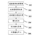
在操作201,在输入图像中进行人脸检测。In
在操作202,根据人脸所在位置初始化待求解的变量,即模型参数p,q,p′,q′。In
在操作203,根据公式(5),计算待求解变量的增量。In
在操作204,使用求出的增量更新待求解的变量。In
在操作205,确定迭代过程是否收敛。当确定没有收敛时,返回步骤203。At
当确定收敛时,在操作206,根据收敛后的模型参数,判断跟踪是否成功。当判断跟踪成功时,在操作207,使用迭代收敛后的模型参数计算模型中的顶点坐标S和S′。当判断跟踪没有成功时,在操作208,忽略当前帧输入图像。When the convergence is determined, in
在操作205中,判断迭代过程收敛的条件可以是待求解变量的在连续若干步迭代后的变化幅度小于预定阈值,也可以是代价函数E或组成代价函数E的两项(即,‖I(G(p,q))-a‖2和k‖S(p,q)-P(S′(p′,q′))‖2)中的某一项的值小于预定阈值,也可以是代价函数E或组成代价函数E的两项中的某一项的在连续若干步迭代后的变化幅度小于预定阈值,也可以是迭代次数达到预定阈值,也可以是其他可以判断迭代是否应该结束的条件。In
在操作206中,判断跟踪是否成功,判断跟踪是否成功的条件为是代价函数E或组成代价函数E的两项中的某一项的值小于预定阈值。In
在对输入图像的序列进行处理时,如果前一帧的跟踪结果是成功的,则可以不对当前帧进行操作201和202,而使用前一帧收敛后的模型参数作为当前帧的初始值,或者使用前若干帧收敛后的模型参数进行预测,使用预测的值作为当前帧的初始值。When processing the sequence of input images, if the tracking result of the previous frame is successful,
通过使用头部视频处理模块进行头部跟踪,可以得到用户面部关键点在图像中的二维坐标S和在空间中的三维坐标S′。By using the head video processing module for head tracking, the two-dimensional coordinates S of the key points of the user's face in the image and the three-dimensional coordinates S' in space can be obtained.
上面示出了一个利用形状可变的头部模型对头部进行跟踪以获得面部关键点的坐标的示例。然而,本领域的技术人员应该理解,其他任何形状可变的头部模型或头部跟踪方法都可以应用于本发明来获得面部跟踪点的坐标。例如,上面了示例在使用三维头部模型的同时还使用了二维头部模型和表观模型辅助跟踪以获得更准确的跟踪结果,然而可仅使用现有技术的形状可变的三维头部模型来进行跟踪。The above shows an example of using a shape-variable head model to track the head to obtain the coordinates of facial key points. However, those skilled in the art should understand that any other shape-variable head model or head tracking method can be applied to the present invention to obtain the coordinates of the face tracking points. For example, the above example uses a 2D head model and an appearance model to assist tracking while using a 3D head model to obtain more accurate tracking results. However, only the shape-variable 3D head of the prior art can be used model to track.
图13示出根据本发明实施例的眼部视频处理模块130的框图。FIG. 13 shows a block diagram of an eye
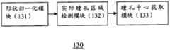
眼部视频处理模块130可包括形状归一化模块131、实际瞳孔区域检测模块132、瞳孔中心获取模块133。The eye
形状归一化模块131根据面部关键点的二维坐标或三维坐标获得眼部纹理图像,并计算形状归一化的眼部纹理图像。实际瞳孔区域检测模块132从形状归一化的眼部纹理图像中检测实际瞳孔区域。瞳孔中心获取模块133根据实际瞳孔区域确定瞳孔中心的坐标,并通过对瞳孔中心的坐标进行逆形状归一化,来计算瞳孔中心在输入图像中的坐标。The shape normalization module 131 obtains the eye texture image according to the two-dimensional or three-dimensional coordinates of the facial key points, and calculates the shape-normalized eye texture image. The actual pupil region detection module 132 detects the actual pupil region from the shape-normalized eye texture image. The pupil center acquisition module 133 determines the coordinates of the pupil center according to the actual pupil area, and calculates the coordinates of the pupil center in the input image by performing inverse shape normalization on the coordinates of the pupil center.
图3示出根据本发明实施例的计算瞳孔中心坐标的处理的流程图。Fig. 3 shows a flowchart of a process of calculating pupil center coordinates according to an embodiment of the present invention.
在操作301,形状归一化模块131根据面部关键点的二维坐标或三维坐标获得左右眼的眼部纹理图像并计算左右眼的形状归一化的眼部纹理图像。In
将包括在面部关键点中的眼部关键点映射到输入图像上,连接映射到输入图像上的关键点形成网格(例如,三角形网格、多边形网格等),这些网格所覆盖的像素作为眼部纹理,这些像素构成的图像称为眼部纹理图像。可分别通过对左眼和右眼的眼部关键点进行上述映射操作来分别得到左眼和右眼的眼部纹理图像。Map the eye key points included in the face key points to the input image, connect the key points mapped to the input image to form a grid (for example, triangular grid, polygonal grid, etc.), and the pixels covered by these grids As an eye texture, the image formed by these pixels is called an eye texture image. The eye texture images of the left eye and the right eye can be respectively obtained by performing the above mapping operations on the eye key points of the left eye and the right eye.
这里,形状归一化的眼部纹理图像是指去除了由变形和/或大小形状导致的个体差异的眼部纹理图像。可通过将眼部纹理图像所覆盖的像素变换到规范化的纹理模板中来获得形状归一化的眼部纹理图像。Here, the shape-normalized eye texture image refers to the eye texture image from which individual differences caused by deformation and/or size and shape have been removed. The shape-normalized eye texture image can be obtained by transforming the pixels covered by the eye texture image into a normalized texture template.
具体地说,对于每个网格,根据网格的顶点(即,眼部关键点)的坐标与该网格所覆盖的像素的位置关系,将该网格所覆盖的像素变换到规范化的纹理模板中对应的网格中,从而得到归一化的纹理图像。可通过将在眼部处于预定形状(例如,平均形状)的条件下的眼部关键点的三维坐标投影到一个平面上,并连接映射到该平面上的关键点形成网格,来得到规范化的纹理模板。Specifically, for each grid, according to the coordinates of the vertices of the grid (i.e., eye keypoints) and the positional relationship between the pixels covered by the grid, the pixels covered by the grid are transformed into a normalized texture In the corresponding grid in the template, a normalized texture image is obtained. The normalized can be obtained by projecting the 3D coordinates of key points of the eye under the condition that the eye is in a predetermined shape (eg, average shape) onto a plane, and connecting the key points mapped to the plane to form a grid. texture template.
优选地,该平面为由眼部关键点在空间中形成的眼部所正对或背对的一个平面(也即,面部关键点在空间中形成的面部所正对或背对的一个平面)。此时,归一化的纹理图像也可以更好的消除由于姿态引起的形变。Preferably, the plane is a plane facing or facing away from the eyes formed by the key points of the eyes in space (that is, a plane facing or facing away from the face formed by the key points of the face in space) . At this time, the normalized texture image can also better eliminate the deformation caused by pose.
例如,可将眼部处于预定形状的三维头部模型的眼部关键点投影到三维头部模型的脸部所正对或背对的平面上,并连接映射到该平面上的关键点形成网格来得到规范化的纹理模板。For example, the key points of the eyes of the 3D head model whose eyes are in a predetermined shape can be projected onto the plane facing or facing away from the face of the 3D head model, and the key points mapped to the plane can be connected to form a network. grid to get a normalized texture template.
此外,也可直接使用眼部处于预定形状的二维头部模型作为规范化的纹理模板。In addition, a two-dimensional head model with eyes in a predetermined shape can also be directly used as a normalized texture template.
换句话说,由于处于不同变形和/或形状时面部关键点被投影到所述平面上的坐标是不同的,相应地得到的纹理也是不同的。通过上述处理,纹理(即,各个网格内覆盖的像素)被归一化,从而消除了变形和/或形状的个体差异。例如,在形状归一化的眼部纹理图像中,用户头部姿态产生的变形以及用户眼睛大小形状的个体差异都可被消除。这样,在视线跟踪过程中,即使用户的面部表情和/或姿态发生变化,也能精确地进行视线跟踪。In other words, since the coordinates at which facial key points are projected onto the plane are different in different deformations and/or shapes, correspondingly obtained textures are also different. Through the above processing, textures (ie, pixels covered within each grid) are normalized, thereby eliminating individual differences in deformation and/or shape. For example, in the shape-normalized eye texture image, the deformation caused by the user's head posture and the individual differences in the size and shape of the user's eyes can be eliminated. In this way, gaze tracking can be accurately performed even if the user's facial expression and/or posture changes during the gaze tracking process.
在操作302,对归一化的纹理图像进行预处理,例如,进行灰度调整(如直方图均衡化)、图像噪声去除(如高斯平滑)等。在本发明中,操作302也可以省略。In
在操作303,实际瞳孔区域检测模块132从左右眼的纹理图像中检测左右瞳孔候选区域。In
在检测瞳孔候选区域时,采用窗口对纹理图像进行扫描。可以选择不同的窗口的形状,如图4所示。在图4示出的每个窗口中,实线以内的区域称为窗口区域,阴影区域称为窗口边缘区域。窗口的尺寸、长宽比以及位置需要遍历所有合理范围内的值。在扫描过程中,对于每一组尺寸、长宽比以及位置参数,可以按照下式的定义计算一个分数值:When detecting pupil candidate regions, a window is used to scan the texture image. Different window shapes can be selected, as shown in Figure 4. In each window shown in FIG. 4 , the area inside the solid line is called the window area, and the shaded area is called the window edge area. The size, aspect ratio, and position of the window need to traverse all reasonable values. During the scanning process, for each set of size, aspect ratio and position parameters, a fractional value can be calculated according to the definition of the following formula:
其中,R表示窗口区域,ER表示窗口边缘区域,x表示像素坐标,I(x)为在像素坐标x处的像素的亮度,▽I(x)表示在像素坐标x处的亮度梯度,N为窗口区域内像素的个数,
在操作304,实际瞳孔区域检测模块132从检测的左右瞳孔候选区域中确定左右瞳孔区域。In
因为用户的双眼注视方向是相同的,所以左右瞳孔位置在左右眼的眼部纹理图像中的相对位置应该是非常接近的。这样,可以根据左右瞳孔候选区域在左右眼的归一化的纹理图像中的相对位置,从左右瞳孔候选区域中确定出一对真正的左右瞳孔区域。Because the gaze direction of the user's eyes is the same, the relative positions of the left and right pupils in the eye texture images of the left and right eyes should be very close. In this way, a pair of true left and right pupil regions can be determined from the left and right pupil candidate regions according to the relative positions of the left and right pupil candidate regions in the normalized texture image of the left and right eyes.
在一个实施例中,从所有的左瞳孔候选区域与所有的右瞳孔候选区域的所有配对中,去除相对位置差别大于预定阈值的配对。然后,从剩下的配对中选出分数值之和最小的一对候选区域,作为真实的左右瞳孔区域的确定结果。In one embodiment, from all pairs of all left pupil candidate areas and all right pupil candidate areas, pairs whose relative position difference is greater than a predetermined threshold are removed. Then, a pair of candidate regions with the smallest sum of scores is selected from the remaining pairings as the determination result of the real left and right pupil regions.
在操作305,实际瞳孔区域检测模块132根据左右瞳孔区域确定与实际的左右瞳孔区域对应的区域(即,实际瞳孔区域)。In
由于扫描窗口的形状与左右瞳孔实际可见的区域的形状不一定完全一致,所以需要从中提取与实际的左右瞳孔区域对应的区域。由于瞳孔与眼球的其他区域在颜色、亮度等方面有显著的区别,因此可以采用其他的模式识别方法来进行提取。Since the shape of the scan window is not necessarily completely consistent with the shape of the area actually visible to the left and right pupils, it is necessary to extract areas corresponding to the actual left and right pupil areas. Since the pupil is significantly different from other areas of the eyeball in terms of color and brightness, other pattern recognition methods can be used for extraction.
在本发明的另一个实施例中,为了解决扫描窗口可能比实际的左右瞳孔区域对应的区域小或与实际的左右瞳孔区域对应的区域形状不一致的问题,在已经确定左右瞳孔区域的条件下,对瞳孔区域进行优化,即调整扫描窗口的轮廓形状使其与实际的瞳孔区域一致,从而得到与实际的左右瞳孔区域对应的区域。In another embodiment of the present invention, in order to solve the problem that the scanning window may be smaller than the area corresponding to the actual left and right pupil areas or the shape of the area corresponding to the actual left and right pupil areas is inconsistent, under the condition that the left and right pupil areas have been determined, Optimizing the pupil area means adjusting the contour shape of the scan window to be consistent with the actual pupil area, so as to obtain areas corresponding to the actual left and right pupil areas.
图7示出根据本发明实施例的对瞳孔区域进行优化的处理的流程图。Fig. 7 shows a flowchart of the process of optimizing the pupil area according to an embodiment of the present invention.
在操作701,根据当前瞳孔区域中像素亮度均值,设置大于等于亮度均值的拒绝阈值、以及小于等于亮度均值的接受阈值。在开始时,当前瞳孔区域即为扫描窗口覆盖的范围。In operation 701 , according to the pixel brightness average value in the current pupil region, a rejection threshold value greater than or equal to the brightness average value and an acceptance threshold value smaller than or equal to the brightness average value are set. At the beginning, the current pupil area is the area covered by the scan window.
在操作702,确定在当前瞳孔区域的内部与当前瞳孔区域的边缘相邻的像素中是否存在亮度大于拒绝阈值的像素,并确定在当前瞳孔区域的外部与当前瞳孔区域的边缘相邻的像素中是否存在亮度小于接受阈值的像素。In operation 702, it is determined whether there is a pixel having a brightness greater than a rejection threshold among the pixels adjacent to the edge of the current pupil area inside the current pupil area, and it is determined whether there is a pixel adjacent to the edge of the current pupil area outside the current pupil area Whether there are pixels with brightness less than the acceptance threshold.
当存在亮度大于拒绝阈值的像素时,在操作703,将亮度大于拒绝阈值的像素从窗口范围中移除。当存在亮度小于接受阈值的像素时,在操作703,将亮度小于接受阈值的像素添加到窗口区域中。在操作703之后进行操作704。When there are pixels with luminance greater than the rejection threshold, in operation 703, the pixels with luminance greater than the rejection threshold are removed from the window range. When there are pixels with brightness less than the acceptance threshold, in operation 703, the pixels with brightness less than the acceptance threshold are added to the window area. Operation 704 is performed after operation 703 .
当不存在亮度大于拒绝阈值的像素并且不存在亮度小于接受阈值的像素时,结束优化处理。When there are no pixels with luminance greater than the reject threshold and no pixels with luminance less than the acceptance threshold, the optimization process ends.
在操作704,对当前瞳孔区域的轮廓进行平滑。具体地,将四邻域(即,上、下、左、右邻域)都为瞳孔区域外像素的像素置为瞳孔区域外像素,将四邻域都为瞳孔区域内像素的像素置为瞳孔区域内像素。在操作704之后进行操作701。In operation 704, the contour of the current pupil region is smoothed. Specifically, the pixels whose four neighborhoods (that is, upper, lower, left, and right neighborhoods) are all pixels outside the pupil area are set as pixels outside the pupil area, and the pixels whose four neighborhoods are all pixels in the pupil area are set as inside the pupil area pixels. Operation 701 is performed after operation 704 .
图5示出对瞳孔区域进行优化的过程的一个示例。在图5的每幅图中,阴影矩形表示亮度小于接受阈值的像素,白色矩形表示亮度大于拒绝阈值的像素,粗黑线表示当前瞳孔区域轮廓。图5(a)为第一步迭代,标有“+”的像素为将要添加到瞳孔区域中的像素,标有“-”的像素为将要从瞳孔区域中移除的像素。经过添加和移除处理后的瞳孔区域如图5(b)所示。经过平滑操作后的瞳孔区域如图5(c)所示。图5(c)示出了在第二步迭代中将要添加或移除的像素。图5(d)为两步迭代后的瞳孔区域。Figure 5 shows an example of a process for optimizing the pupil region. In each plot of Fig. 5, shaded rectangles represent pixels with brightness less than the acceptance threshold, white rectangles represent pixels with brightness greater than the rejection threshold, and thick black lines represent the current pupil region outline. Figure 5(a) is the first iteration, the pixels marked with "+" are the pixels to be added to the pupil area, and the pixels marked with "-" are the pixels to be removed from the pupil area. The pupil region after adding and removing is shown in Fig. 5(b). The pupil region after the smoothing operation is shown in Fig. 5(c). Figure 5(c) shows the pixels to be added or removed in the second iteration. Figure 5(d) shows the pupil area after two iterations.
在操作306,瞳孔中心获取模块133从实际左右瞳孔区域确定左右瞳孔中心,并计算左右瞳孔中心在输入图像中的坐标。In
对实际瞳孔区域,使用如下公式计算其中心位置:For the actual pupil area, use the following formula to calculate its center position:
其中C为瞳孔中心坐标,x为瞳孔区域内像素的横坐标,y为瞳孔区域内像素的纵坐标,N为瞳孔区域内像素的个数。Where C is the center coordinate of the pupil, x is the abscissa of the pixel in the pupil area, y is the ordinate of the pixel in the pupil area, and N is the number of pixels in the pupil area.
随后,将瞳孔中心坐标进行逆形状归一化来计算瞳孔中心在输入图像中的坐标。具体地说,根据瞳孔中心所在网格的顶点坐标,将瞳孔中心坐标C反变换到输入图像中,得到瞳孔中心在输入图像中的坐标。Then, the coordinates of the pupil center are subjected to inverse shape normalization to calculate the coordinates of the pupil center in the input image. Specifically, according to the vertex coordinates of the grid where the pupil center is located, the pupil center coordinate C is inversely transformed into the input image, and the coordinates of the pupil center in the input image are obtained.
操作303-305示出了一个检测实际瞳孔区域的示例。然而,本领域的技术人员应该理解,也可以使用其他的模式识别方法来检测实际瞳孔区域,例如,可以通过训练分类器的方式来从归一化的眼部纹理图像中检测际瞳孔区域。Operations 303-305 illustrate an example of detecting the actual pupil area. However, those skilled in the art should understand that other pattern recognition methods can also be used to detect the actual pupil area, for example, the inter-pupil area can be detected from the normalized eye texture image by training a classifier.
图14示出根据本发明实施例的视线方向计算模块140的框图。FIG. 14 shows a block diagram of the gaze
视线方向计算模块140包括左右眼视线检测模块141和用户视线检测模块142。The gaze
左右眼视线检测模块141根据左眼的瞳孔中心的三维坐标和左眼的眼球中心的三维坐标,计算左眼的瞳孔中心与左眼的眼球中心确定的直线作为左眼的视线方向,根据右眼的瞳孔中心的三维坐标和右眼的眼球中心的三维坐标,计算右眼的瞳孔中心与右眼的眼球中心确定的直线作为右眼的视线方向。The left and right eyes sight detection module 141 calculates the straight line determined by the pupil center of the left eye and the eyeball center of the left eye as the line of sight direction of the left eye according to the three-dimensional coordinates of the pupil center of the left eye and the three-dimensional coordinates of the eyeball center of the left eye. The three-dimensional coordinates of the pupil center and the three-dimensional coordinates of the eyeball center of the right eye are calculated, and the straight line determined by the pupil center of the right eye and the eyeball center of the right eye is calculated as the line of sight direction of the right eye.
用户视线检测模块142根据左眼的视线方向与右眼的视线方向确定用户的视线方向。The user gaze detection module 142 determines the gaze direction of the user according to the gaze direction of the left eye and the gaze direction of the right eye.
图6示出视线方向计算模块140计算视线方向的操作的流程图。FIG. 6 shows a flowchart of the operation of the gaze
在操作601,根据左右瞳孔中心在输入图像中的二维坐标计算左右瞳孔中心在空间中的三维坐标。可通过将瞳孔中心的二维坐标映射到面部关键点的三维坐标所在的坐标系来获得瞳孔中心的三维坐标。In
例如,当使用三维头部模型获得面部关键点的三维坐标时,将该二维坐标映射到三维头部模型可以获得瞳孔中心的三维坐标。由于从输入图像跟踪头部,而输入图像中的头部姿态是以视频采集模块110为参考的(例如,当用户的头部正对着视频采集模块110时,输入图像中的头部姿态看起来也是正对着观众),因此,在进行跟踪时的三维头部模型的三维坐标也是以视频采集模块110为参考的。这样,为了获得瞳孔中心的三维坐标,根据每个瞳孔中心在输入图像中的二维坐标,确定每个瞳孔中心在视频采集模块110的图像传感器(例如,CCD传感器、CMOS传感器)上的成像位置的三维坐标。此时,存在连接视频采集模块110的镜头的光心和一个瞳孔中心的成像位置的一条直线,该直线与三维头部模型的交点即为瞳孔中心,该交点的三维坐标即为瞳孔中心的三维坐标。For example, when using a 3D head model to obtain the 3D coordinates of facial key points, mapping the 2D coordinates to the 3D head model can obtain the 3D coordinates of the pupil center. Since the head is tracked from the input image, the head pose in the input image is based on the video capture module 110 (for example, when the user's head is facing the
在操作602,计算左右眼球中心在空间中的三维坐标。In
下面,示出计算眼球中心的三维坐标的几个示例。Next, several examples of calculating the three-dimensional coordinates of the eyeball center are shown.
在一个实施例中,可基于眼球中心与头部关键点的位置关系来确定眼球中心的三维坐标。对于不同的个体,在三维头部模型中,眼球中心与用于表示眼睛轮廓的几个点的相对位置关系是很接近的。在精度要求不高的使用条件下,可以使用经验值来计算眼球中心在空间中的三维坐标。In one embodiment, the three-dimensional coordinates of the eyeball center can be determined based on the positional relationship between the eyeball center and the key points of the head. For different individuals, in the three-dimensional head model, the relative positional relationship between the center of the eyeball and several points used to represent the outline of the eye is very close. Under the conditions of use where the precision is not high, empirical values can be used to calculate the three-dimensional coordinates of the eyeball center in space.
例如,可利用下面的等式来计算眼球中心在空间中的三维坐标:For example, the following equation can be used to calculate the three-dimensional coordinates of the eyeball center in space:
xM=xB+α(xK-xB),xM =xB +α(xK -xB ),
其中,xK为左右眼角的连线的中点的坐标;xB为上下眼眶的中点的连线的中点的坐标,α近似地取3.5左右的值。左右眼角、眼眶中点通常作为面部关键点,其坐标可以由头部视频处理模块120得到。例如,xK和xB可以从三维头部模型得到。Among them, xK is the coordinates of the midpoint of the line connecting the left and right eye corners; xB is the coordinates of the midpoint of the line connecting the midpoints of the upper and lower eye sockets, and α approximately takes a value of about 3.5. The left and right eye corners and the midpoint of the orbit are usually used as facial key points, and their coordinates can be obtained by the head
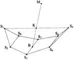
如图8所示,S1到S8为对应于一只眼睛轮廓的8个顶点(即,关键点),B为上眼眶的中点S3和下眼眶的中点S7的连线的中点,B的坐标对应于xB;K为左眼角S1和右眼角S5的连线的中点,K的坐标对应于xK;M为眼球中心,M的坐标xM可使用上面的等式计算。As shown in Figure 8, S1 to S8 are 8 vertices (that is, key points) corresponding to the outline of an eye, and B is the connection line between the midpoint S3 of the upper orbit and the midpoint S7 of the lower orbit. Midpoint, the coordinates of B correspond to xB ; K is the midpoint of the line connecting the left eye cornerS1 and the right eye cornerS5 , and the coordinates of K correspond to xK ; M is the eyeball center, and the coordinate xM of M can use the above equation calculation.
在操作603,根据确定的左右瞳孔中心和左右眼球中心计算左右眼的视线方向,左眼的瞳孔中心与左眼的眼球中心确定的直线为左眼的视线方向;右眼的瞳孔中心与右眼的眼球中心确定的直线为右眼的视线方向。如图12所示,每只眼的视线方向即瞳孔中心U与眼球中心M这两个点确定的直线,U和M的坐标在前面的步骤中都已经求出,所以左眼和右眼的视线方程都可以得到。In
在操作604,对在操作603计算的左右眼的视线方向进行融合。如果左右眼视线共面,则最终的视线为左右眼视线交点与左右眼球中心中点确定的直线;如果左右眼视线异面,则最终的视线为左右眼视线公垂线中点与左右眼球中心的中点确定的直线。In
在上面的实施例中,通过使用经验值来计算眼球中心在空间中的三维坐标。为了获得更高的精度,在操作602中也可通过校准的方式来确定眼球中心的三维坐标。In the above embodiments, the three-dimensional coordinates of the eyeball center in space are calculated by using empirical values. In order to obtain higher precision, in
图9示出根据本发明实施例的通过标定的方式来确定眼球中心的三维坐标的流程图。Fig. 9 shows a flow chart of determining the three-dimensional coordinates of the eyeball center by means of calibration according to an embodiment of the present invention.
视线跟踪之前进行标定。在标定过程中,用户的头部姿态应保持不变。Calibration before eye tracking. During the calibration process, the user's head pose should remain unchanged.
在操作901,在空间中设置至少两个标定点。In
在操作902,用户依次注视这些标定点,注视每一个标定点时,记录下标定点的三维坐标以及当时的面部关键点的三维坐标和左右瞳孔中心的三维坐标。可通过前面描述的方式来计算面部关键点的三维坐标和左右瞳孔中心的三维坐标。In
在操作903,利用每个标定点三维坐标以及对应的左右瞳孔中心的三维坐标,得到由标定点与左瞳孔中心确定的左眼标定视线以及由标定点与右瞳孔中心确定的右眼标定视线。In
在操作904,分别基于左眼标定视线的交点和右眼标定视线的交点,估算左右眼球中心的三维坐标。In
图10示出标定原理的示意图。在图10中,存在三个标定点T1、T2和T3。这样,对于每个眼球,在标定过程中可以得到相应的三个瞳孔中心的三维坐标U1、U2和U3。此时,直线T1-U1、T2-U2、T3-U3的交点即为眼球中心M。Fig. 10 shows a schematic diagram of the calibration principle. In Fig. 10, there are three calibration pointsT1 ,T2 andT3 . In this way, for each eyeball, the three-dimensional coordinates U1 , U2 and U3 of the corresponding three pupil centers can be obtained during the calibration process. At this time, the intersection of the straight lines T1 -U1 , T2 -U2 , and T3 -U3 is the center M of the eyeball.
应该理解,在标定点的数量大于等于2时,都可以实现标定。It should be understood that when the number of calibration points is greater than or equal to 2, calibration can be implemented.
在操作903,可利用部分面部关键点(例如,对应于眼睛轮廓的几个关键点)的坐标来表示左右眼球中心的三维坐标。In
在视线方向跟踪过程中,由于用户头部姿态是运动的,眼球中心在空间中的位置也会发生改变。而上述标定过程是在头部姿态不变的情况下得到的。因此,在操作902得到的左右眼球中心的三维坐标不能用于其它头部姿态。这样,需要使用面部关键点的坐标来表示左右眼球中心的三维坐标。在视线跟踪过程中,可根据头部视频处理模块120跟踪的面部关键点的三维坐标来确定左右眼球中心的三维坐标。During the gaze direction tracking process, since the user's head posture is moving, the position of the eyeball center in space will also change. The above calibration process is obtained under the condition that the head pose remains unchanged. Therefore, the three-dimensional coordinates of the left and right eyeball centers obtained in
图11示出通过面部关键点的三维坐标来确定一个眼球中心的三维坐标的另一个实施例。Fig. 11 shows another embodiment of determining the three-dimensional coordinates of an eyeball center through the three-dimensional coordinates of facial key points.
如图11所示,S1到S8为对应于一只眼睛轮廓的8个关键点。定义向量KS5为e1,向量BK为e2,向量BS7为e3,其中K为S1S5的中点,B为S3S7的中点。用e1,e2,e3的线性组合表示眼球中心的坐标xM,系数用向量b表示,则b可以通过求解下述方程获得:As shown in Figure 11, S1 to S8 are 8 key points corresponding to the outline of an eye. Define vector KS5 as e1 , vector BK as e2 , and vector BS7 as e3 , where K is the midpoint of S1 S5 and B is the midpoint of S3 S7 . Use the linear combination of e1 , e2 , e3 to represent the coordinate xM of the center of the eyeball, and the coefficient is represented by vector b, then b can be obtained by solving the following equation:
[e1 e2 e3]b=xM (8)[e1 e2 e3 ]b=xM (8)
在视线方向跟踪过程中,关键点的坐标及按照上述方式定义的向量e1,e2,e3随用户头部的运动而变化,但系数向量b不变。这样,眼球中心的坐标可以用当前帧的向量e1,e2,e3与系数向量b相乘获得。During the gaze direction tracking process, the coordinates of the key points and the vectors e1 , e2 , and e3 defined in the above manner change with the movement of the user's head, but the coefficient vector b remains unchanged. In this way, the coordinates of the eyeball center can be obtained by multiplying the vector e1 , e2 , e3 of the current frame with the coefficient vector b.
以上,利用多条视线估算眼球中心在空间的三维坐标的原理,在图10中进行了说明。其中,Ti(i为标定点的编号,i=0,1,...)为手工布置的标定点的三维坐标,Ui为用户注视Ti时的左(或右)瞳孔中心点的三维坐标。如果Ti与Ui的连线在空间中相交于一点,则这一点即为左(或右)眼眼球中心。在一些情况下,由于对瞳孔中心的定位存在一定误差,这些左(或右)眼标定视线为空间异面直线。可用参数方程表示这些直线:Above, the principle of estimating the three-dimensional coordinates of the eyeball center in space by using multiple lines of sight is illustrated in FIG. 10 . Among them, Ti (i is the number of the calibration point, i=0, 1, ...) is the three-dimensional coordinates of the calibration point arranged manually, Ui is the center point of the left (or right) pupil when the user looks at Ti 3D coordinates. If the line connecting Ti and Ui intersects at a point in space, then this point is the eyeball center of the left (or right) eye. In some cases, due to a certain error in the positioning of the pupil center, these left (or right) eyes mark the line of sight as a spatially different plane straight line. These lines can be represented by parametric equations:
Ui+ti(Ti-Ui) (9)Ui +ti (Ti -Ui ) (9)
其中ti为直线方程的参数。左(或右)眼眼球的中心M通过最小化下面的目标函数的方法计算:Where ti is the parameter of the straight line equation. The center M of the left (or right) eyeball is calculated by minimizing the following objective function:
其中D(TiUi,M)表示M到Ti与Ui确定的直线的距离。Wherein D(Ti Ui , M) represents the distance from M to the straight line determined by Ti and Ui .
在一个实施例中,这个最小化问题可以通过求解下面的线性方程得到最优解:In one embodiment, this minimization problem can be optimally solved by solving the following linear equation:

其中,K为左(或右)眼标定视线的数量。Among them, K is the number of calibrated sight lines of the left (or right) eye.
应该理解,其他的最小化优化方法也可以可行的。It should be understood that other minimization optimization methods may also work.
上面示出了计算眼球中心的三维坐标的几个实施例。应该理解,其他已知的确定眼球中心的三维坐标的方法也可应用于本发明中。Several embodiments for calculating the three-dimensional coordinates of the eyeball center are shown above. It should be understood that other known methods for determining the three-dimensional coordinates of the eyeball center can also be applied in the present invention.
在上面的示例中,针对每只眼睛对瞳孔中心和眼球中心进行定位,通过融合左右眼视线来确定最终的用户视线方向。然而,在用户仅使用一只眼睛(左眼或右眼)的时候,可仅针对该眼睛对瞳孔中心和眼球中心进行定位,该眼睛的视线方向为最终的用户视线方向。In the above example, the pupil center and eyeball center are positioned for each eye, and the final user's line of sight direction is determined by fusing the line of sight of the left and right eyes. However, when the user only uses one eye (left eye or right eye), the pupil center and eyeball center can be positioned only for this eye, and the line of sight direction of this eye is the final line of sight direction of the user.
根据本发明的视线跟踪方法和设备,其只使用一个普通摄像头捕获的视频图像就可以准确跟踪用户的视线方向。另外,在视线跟踪过程中,用户的头部可以在较大的范围内平移和旋转,并且允许面部表情改变。According to the eye-tracking method and device of the present invention, it can accurately track the user's eye-line direction only by using a video image captured by a common camera. In addition, the user's head can be translated and rotated within a large range during gaze tracking, and facial expressions are allowed to change.
在此使用的术语“模块”的意思是(但不限于)软件或硬件组件。本领域的技术人员根据对相应的“模块”的描述,可以通过诸如可执行特定任务的现场可编程门阵列(FPGA)或专用集成电路(ASIC)来实现相应的模块。The term "module" as used herein means, but is not limited to, a software or hardware component. Those skilled in the art may realize the corresponding modules through, for example, a Field Programmable Gate Array (FPGA) or an Application Specific Integrated Circuit (ASIC) capable of performing specific tasks according to the description of the corresponding "module".
尽管已经参照其示例性实施例具体显示和描述了本发明,但是本领域的技术人员应该理解,在不脱离权利要求所限定的本发明的精神和范围的情况下,可以对其进行形式和细节上的各种改变。While the invention has been particularly shown and described with reference to exemplary embodiments thereof, it will be understood by those skilled in the art that changes may be made in form and detail without departing from the spirit and scope of the invention as defined by the claims. various changes.
Claims (16)

Priority Applications (1)
| Application Number | Priority Date | Filing Date | Title |
|---|---|---|---|
| CN201110167218.2ACN102830793B (en) | 2011-06-16 | 2011-06-16 | Sight tracing and equipment |
Applications Claiming Priority (1)
| Application Number | Priority Date | Filing Date | Title |
|---|---|---|---|
| CN201110167218.2ACN102830793B (en) | 2011-06-16 | 2011-06-16 | Sight tracing and equipment |
Publications (2)
| Publication Number | Publication Date |
|---|---|
| CN102830793Atrue CN102830793A (en) | 2012-12-19 |
| CN102830793B CN102830793B (en) | 2017-04-05 |
Family
ID=47333962
Family Applications (1)
| Application Number | Title | Priority Date | Filing Date |
|---|---|---|---|
| CN201110167218.2AExpired - Fee RelatedCN102830793B (en) | 2011-06-16 | 2011-06-16 | Sight tracing and equipment |
Country Status (1)
| Country | Link |
|---|---|
| CN (1) | CN102830793B (en) |
Cited By (72)
| Publication number | Priority date | Publication date | Assignee | Title |
|---|---|---|---|---|
| CN104036586A (en)* | 2014-06-09 | 2014-09-10 | 京东方科技集团股份有限公司 | Eye-controlled display device and display method thereof and ATM (Automatic Teller Machine) machine system |
| CN104615978A (en)* | 2015-01-23 | 2015-05-13 | 清华大学 | Sight direction tracking method and device |
| CN104808778A (en)* | 2014-01-24 | 2015-07-29 | 北京奇虎科技有限公司 | Device and method for determining validity of operation of head-wearing intelligent device |
| CN104822005A (en)* | 2014-01-30 | 2015-08-05 | 京瓷办公信息系统株式会社 | Electronic device and operation picture display method |
| CN104834381A (en)* | 2015-05-15 | 2015-08-12 | 中国科学院深圳先进技术研究院 | Wearable device for sight focus positioning and sight focus positioning method |
| CN104837049A (en)* | 2014-02-06 | 2015-08-12 | 三星电子株式会社 | User terminal apparatus, display apparatus, and control methods thereof |
| CN104905764A (en)* | 2015-06-08 | 2015-09-16 | 四川大学华西医院 | High-speed sight tracking method based on FPGA |
| CN104951808A (en)* | 2015-07-10 | 2015-09-30 | 电子科技大学 | 3D (three-dimensional) sight direction estimation method for robot interaction object detection |
| CN105184246A (en)* | 2015-08-28 | 2015-12-23 | 北京旷视科技有限公司 | Living body detection method and living body detection system |
| CN105512119A (en)* | 2014-09-22 | 2016-04-20 | 中兴通讯股份有限公司 | Image ranking method and terminal |
| CN105828699A (en)* | 2013-12-17 | 2016-08-03 | 埃西勒国际通用光学公司 | Device And Method For Measuring Subjective Refraction |
| CN105892632A (en)* | 2015-11-16 | 2016-08-24 | 乐视致新电子科技(天津)有限公司 | Method and device for judging the selection of UI (User Interface) widgets of virtual reality application |
| CN106127552A (en)* | 2016-06-23 | 2016-11-16 | 北京理工大学 | A kind of virtual scene display method, Apparatus and system |
| CN106249870A (en)* | 2015-06-15 | 2016-12-21 | 哈曼国际工业有限公司 | Passive magnetic head-tracker |
| CN106462869A (en)* | 2014-05-26 | 2017-02-22 | Sk 普兰尼特有限公司 | Apparatus and method for providing advertisement using pupil tracking |
| CN106462733A (en)* | 2014-05-19 | 2017-02-22 | 微软技术许可有限责任公司 | Gaze detection calibration |
| CN106504271A (en)* | 2015-09-07 | 2017-03-15 | 三星电子株式会社 | Method and apparatus for eye tracking |
| CN106575152A (en)* | 2014-07-23 | 2017-04-19 | 微软技术许可有限责任公司 | Alignable user interface |
| CN106598221A (en)* | 2016-11-17 | 2017-04-26 | 电子科技大学 | Eye key point detection-based 3D sight line direction estimation method |
| CN106599994A (en)* | 2016-11-23 | 2017-04-26 | 电子科技大学 | Sight line estimation method based on depth regression network |
| CN106774950A (en)* | 2017-03-10 | 2017-05-31 | 中国地质大学(武汉) | Spatial data immersion exchange method based on eyeball tracking |
| CN106814846A (en)* | 2016-10-24 | 2017-06-09 | 上海青研科技有限公司 | A kind of eye movement analysis method based on sight line and collision body intersection point in VR |
| CN107111381A (en)* | 2015-11-27 | 2017-08-29 | Fove股份有限公司 | Line-of-sight detection systems, fixation point confirmation method and fixation point confirm program |
| CN107223082A (en)* | 2017-04-21 | 2017-09-29 | 深圳前海达闼云端智能科技有限公司 | A kind of robot control method, robot device and robot device |
| CN107247571A (en)* | 2017-06-26 | 2017-10-13 | 京东方科技集团股份有限公司 | A kind of display device and its display methods |
| CN107577959A (en)* | 2017-10-11 | 2018-01-12 | 厦门美图移动科技有限公司 | A kind of method for secret protection and mobile terminal |
| CN104822005B (en)* | 2014-01-30 | 2018-02-09 | 京瓷办公信息系统株式会社 | Electronic equipment and operation screen display methods |
| CN107991775A (en)* | 2016-10-26 | 2018-05-04 | 中国科学院深圳先进技术研究院 | It can carry out the wear-type visual device and human eye method for tracing of people's ocular pursuit |
| CN108156387A (en)* | 2018-01-12 | 2018-06-12 | 深圳奥比中光科技有限公司 | Terminate the device and method of camera shooting automatically by detecting eye sight line |
| CN108229284A (en)* | 2017-05-26 | 2018-06-29 | 北京市商汤科技开发有限公司 | Eye-controlling focus and training method and device, system, electronic equipment and storage medium |
| CN108289151A (en)* | 2018-01-29 | 2018-07-17 | 维沃移动通信有限公司 | A kind of operating method and mobile terminal of application program |
| CN108345848A (en)* | 2018-01-31 | 2018-07-31 | 广东欧珀移动通信有限公司 | User gaze direction identification method and related product |
| CN108427926A (en)* | 2018-03-16 | 2018-08-21 | 西安电子科技大学 | A kind of pupil positioning method in gaze tracking system |
| CN108509029A (en)* | 2018-03-09 | 2018-09-07 | 苏州佳世达电通有限公司 | Contactless input method and contactless input system |
| CN108592865A (en)* | 2018-04-28 | 2018-09-28 | 京东方科技集团股份有限公司 | Geometric measurement method and its device, AR equipment based on AR equipment |
| CN108696732A (en)* | 2017-02-17 | 2018-10-23 | 北京三星通信技术研究有限公司 | Wear the method for adjusting resolution and equipment of display equipment |
| CN109008944A (en)* | 2017-06-09 | 2018-12-18 | 爱信精机株式会社 | Sight measuring device, sight measuring program and sight measuring method |
| CN109145864A (en)* | 2018-09-07 | 2019-01-04 | 百度在线网络技术(北京)有限公司 | Determine method, apparatus, storage medium and the terminal device of visibility region |
| CN109343700A (en)* | 2018-08-31 | 2019-02-15 | 深圳市沃特沃德股份有限公司 | Eye movement controls calibration data acquisition methods and device |
| CN109375765A (en)* | 2018-08-31 | 2019-02-22 | 深圳市沃特沃德股份有限公司 | Eyeball tracking exchange method and device |
| CN109409173A (en)* | 2017-08-18 | 2019-03-01 | 安徽三联交通应用技术股份有限公司 | Driver's state monitoring method, system, medium and equipment based on deep learning |
| CN109446892A (en)* | 2018-09-14 | 2019-03-08 | 杭州宇泛智能科技有限公司 | Human eye notice positioning method and system based on deep neural network |
| CN109583292A (en)* | 2018-10-11 | 2019-04-05 | 杭州电子科技大学 | A kind of visibility region detection method |
| CN109697392A (en)* | 2017-10-23 | 2019-04-30 | 北京京东尚科信息技术有限公司 | Draw the method and device of target object thermodynamic chart |
| CN109726613A (en)* | 2017-10-27 | 2019-05-07 | 虹软科技股份有限公司 | A kind of method and apparatus for detection |
| WO2019085519A1 (en)* | 2017-11-01 | 2019-05-09 | 宁波视睿迪光电有限公司 | Method and device for facial tracking |
| CN109740491A (en)* | 2018-12-27 | 2019-05-10 | 北京旷视科技有限公司 | A human eye sight recognition method, device, system and storage medium |
| CN109902630A (en)* | 2019-03-01 | 2019-06-18 | 上海像我信息科技有限公司 | A kind of attention judgment method, device, system, equipment and storage medium |
| CN110046546A (en)* | 2019-03-05 | 2019-07-23 | 成都旷视金智科技有限公司 | A kind of adaptive line of sight method for tracing, device, system and storage medium |
| CN110045834A (en)* | 2019-05-21 | 2019-07-23 | 广东工业大学 | Detection method, device, system, equipment and storage medium for sight locking |
| CN110051319A (en)* | 2019-04-23 | 2019-07-26 | 七鑫易维(深圳)科技有限公司 | Adjusting method, device, equipment and the storage medium of eyeball tracking sensor |
| CN110244853A (en)* | 2019-06-21 | 2019-09-17 | 四川众信互联科技有限公司 | Gestural control method, device, intelligent display terminal and storage medium |
| CN110335266A (en)* | 2019-07-04 | 2019-10-15 | 五邑大学 | A kind of intelligent traditional Chinese medicine visual diagnosis image processing method and device |
| CN110363555A (en)* | 2018-04-10 | 2019-10-22 | 深圳市阿西莫夫科技有限公司 | Recommended method and device based on eye tracking vision algorithm |
| CN110363133A (en)* | 2019-07-10 | 2019-10-22 | 广州市百果园信息技术有限公司 | A kind of method, apparatus, equipment and the storage medium of line-of-sight detection and video processing |
| CN110381368A (en)* | 2019-07-11 | 2019-10-25 | 北京字节跳动网络技术有限公司 | Video cover generation method, device and electronic equipment |
| CN110503068A (en)* | 2019-08-28 | 2019-11-26 | Oppo广东移动通信有限公司 | Sight estimation method, terminal and storage medium |
| CN110516553A (en)* | 2019-07-31 | 2019-11-29 | 北京航空航天大学 | Working state monitoring method and device |
| CN110555426A (en)* | 2019-09-11 | 2019-12-10 | 北京儒博科技有限公司 | Sight line detection method, device, equipment and storage medium |
| CN110648369A (en)* | 2019-09-23 | 2020-01-03 | 京东方科技集团股份有限公司 | Calibration method and device for sight line calculation model parameters |
| CN110758237A (en)* | 2018-07-27 | 2020-02-07 | 深圳富泰宏精密工业有限公司 | Electronic device and driving safety reminding method |
| TWI691907B (en)* | 2018-06-12 | 2020-04-21 | 網銀國際股份有限公司 | Mobile device and its positioning method in space |
| CN111070214A (en)* | 2018-10-18 | 2020-04-28 | Lg电子株式会社 | Robot |
| CN111723716A (en)* | 2020-06-11 | 2020-09-29 | 深圳地平线机器人科技有限公司 | Method, apparatus, system, medium and electronic device for determining the orientation of a target object |
| CN113129112A (en)* | 2021-05-11 | 2021-07-16 | 杭州海康威视数字技术股份有限公司 | Article recommendation method and device and electronic equipment |
| CN113688733A (en)* | 2021-08-25 | 2021-11-23 | 深圳龙岗智能视听研究院 | Eye detection and tracking method, system, equipment and application based on event camera |
| WO2021249187A1 (en)* | 2020-06-09 | 2021-12-16 | 京东方科技集团股份有限公司 | Gaze tracking method, gaze tracking apparatus, computing device, and medium |
| CN113850145A (en)* | 2021-08-30 | 2021-12-28 | 中国科学院上海微系统与信息技术研究所 | Hand-eye orientation cooperative target positioning method |
| CN114155280A (en)* | 2021-11-30 | 2022-03-08 | 中汽创智科技有限公司 | A binocular gaze tracking method, device and device |
| WO2022193809A1 (en)* | 2021-03-18 | 2022-09-22 | 魔珐(上海)信息科技有限公司 | Gaze capturing method and apparatus, storage medium, and terminal |
| US11487360B1 (en) | 2021-12-21 | 2022-11-01 | Industrial Technology Research Institute | Gaze tracking method and gaze tracking device using ihe same |
| CN119788832A (en)* | 2025-03-04 | 2025-04-08 | 成都工业学院 | A method for fast stereoscopic image conversion |
Citations (4)
| Publication number | Priority date | Publication date | Assignee | Title |
|---|---|---|---|---|
| US20080049186A1 (en)* | 2003-11-07 | 2008-02-28 | Neuro Kinetics, Inc. | Portable high speed head mounted pupil dilation tracking system |
| CN101763636A (en)* | 2009-09-23 | 2010-06-30 | 中国科学院自动化研究所 | Method for tracing position and pose of 3D human face in video sequence |
| CN101901485A (en)* | 2010-08-11 | 2010-12-01 | 华中科技大学 | 3D free head moving type gaze tracking system |
| CN101964111A (en)* | 2010-09-27 | 2011-02-02 | 山东大学 | Method for improving sight tracking accuracy based on super-resolution |
- 2011
- 2011-06-16CNCN201110167218.2Apatent/CN102830793B/ennot_activeExpired - Fee Related
Patent Citations (4)
| Publication number | Priority date | Publication date | Assignee | Title |
|---|---|---|---|---|
| US20080049186A1 (en)* | 2003-11-07 | 2008-02-28 | Neuro Kinetics, Inc. | Portable high speed head mounted pupil dilation tracking system |
| CN101763636A (en)* | 2009-09-23 | 2010-06-30 | 中国科学院自动化研究所 | Method for tracing position and pose of 3D human face in video sequence |
| CN101901485A (en)* | 2010-08-11 | 2010-12-01 | 华中科技大学 | 3D free head moving type gaze tracking system |
| CN101964111A (en)* | 2010-09-27 | 2011-02-02 | 山东大学 | Method for improving sight tracking accuracy based on super-resolution |
Non-Patent Citations (1)
| Title |
|---|
| 汪晓妍等: "综合鲁棒特征和在线学习的自适应三维人脸多特征跟踪", 《计算机科学》* |
Cited By (114)
| Publication number | Priority date | Publication date | Assignee | Title |
|---|---|---|---|---|
| CN105828699A (en)* | 2013-12-17 | 2016-08-03 | 埃西勒国际通用光学公司 | Device And Method For Measuring Subjective Refraction |
| CN104808778B (en)* | 2014-01-24 | 2019-03-01 | 北京奇虎科技有限公司 | Judge the device and method of head-wearing type intelligent equipment operation validity |
| CN104808778A (en)* | 2014-01-24 | 2015-07-29 | 北京奇虎科技有限公司 | Device and method for determining validity of operation of head-wearing intelligent device |
| CN104822005A (en)* | 2014-01-30 | 2015-08-05 | 京瓷办公信息系统株式会社 | Electronic device and operation picture display method |
| CN104822005B (en)* | 2014-01-30 | 2018-02-09 | 京瓷办公信息系统株式会社 | Electronic equipment and operation screen display methods |
| CN104837049A (en)* | 2014-02-06 | 2015-08-12 | 三星电子株式会社 | User terminal apparatus, display apparatus, and control methods thereof |
| US10248199B2 (en) | 2014-05-19 | 2019-04-02 | Microsoft Technology Licensing, Llc | Gaze detection calibration |
| CN106462733B (en)* | 2014-05-19 | 2019-09-20 | 微软技术许可有限责任公司 | A method and computing device for line-of-sight detection calibration |
| CN106462733A (en)* | 2014-05-19 | 2017-02-22 | 微软技术许可有限责任公司 | Gaze detection calibration |
| CN106462869B (en)* | 2014-05-26 | 2020-11-27 | Sk 普兰尼特有限公司 | Apparatus and method for serving advertisements using pupil tracking |
| CN106462869A (en)* | 2014-05-26 | 2017-02-22 | Sk 普兰尼特有限公司 | Apparatus and method for providing advertisement using pupil tracking |
| CN104036586A (en)* | 2014-06-09 | 2014-09-10 | 京东方科技集团股份有限公司 | Eye-controlled display device and display method thereof and ATM (Automatic Teller Machine) machine system |
| CN104036586B (en)* | 2014-06-09 | 2017-01-18 | 京东方科技集团股份有限公司 | Eye-controlled display device and display method thereof and ATM (Automatic Teller Machine) machine system |
| CN106575152B (en)* | 2014-07-23 | 2019-09-27 | 微软技术许可有限责任公司 | The user interface that can be aligned |
| CN106575152A (en)* | 2014-07-23 | 2017-04-19 | 微软技术许可有限责任公司 | Alignable user interface |
| CN105512119A (en)* | 2014-09-22 | 2016-04-20 | 中兴通讯股份有限公司 | Image ranking method and terminal |
| CN104615978B (en)* | 2015-01-23 | 2017-09-22 | 清华大学 | Direction of visual lines tracking and device |
| CN104615978A (en)* | 2015-01-23 | 2015-05-13 | 清华大学 | Sight direction tracking method and device |
| CN104834381A (en)* | 2015-05-15 | 2015-08-12 | 中国科学院深圳先进技术研究院 | Wearable device for sight focus positioning and sight focus positioning method |
| CN104905764A (en)* | 2015-06-08 | 2015-09-16 | 四川大学华西医院 | High-speed sight tracking method based on FPGA |
| CN106249870A (en)* | 2015-06-15 | 2016-12-21 | 哈曼国际工业有限公司 | Passive magnetic head-tracker |
| CN104951808B (en)* | 2015-07-10 | 2018-04-27 | 电子科技大学 | A kind of 3D direction of visual lines methods of estimation for robot interactive object detection |
| CN104951808A (en)* | 2015-07-10 | 2015-09-30 | 电子科技大学 | 3D (three-dimensional) sight direction estimation method for robot interaction object detection |
| CN105184246A (en)* | 2015-08-28 | 2015-12-23 | 北京旷视科技有限公司 | Living body detection method and living body detection system |
| CN106504271A (en)* | 2015-09-07 | 2017-03-15 | 三星电子株式会社 | Method and apparatus for eye tracking |
| CN106504271B (en)* | 2015-09-07 | 2022-01-25 | 三星电子株式会社 | Method and apparatus for eye tracking |
| CN105892632A (en)* | 2015-11-16 | 2016-08-24 | 乐视致新电子科技(天津)有限公司 | Method and device for judging the selection of UI (User Interface) widgets of virtual reality application |
| CN107111381A (en)* | 2015-11-27 | 2017-08-29 | Fove股份有限公司 | Line-of-sight detection systems, fixation point confirmation method and fixation point confirm program |
| CN106127552A (en)* | 2016-06-23 | 2016-11-16 | 北京理工大学 | A kind of virtual scene display method, Apparatus and system |
| CN106127552B (en)* | 2016-06-23 | 2019-12-13 | 北京理工大学 | A virtual scene display method, device and system |
| CN106814846A (en)* | 2016-10-24 | 2017-06-09 | 上海青研科技有限公司 | A kind of eye movement analysis method based on sight line and collision body intersection point in VR |
| CN107991775A (en)* | 2016-10-26 | 2018-05-04 | 中国科学院深圳先进技术研究院 | It can carry out the wear-type visual device and human eye method for tracing of people's ocular pursuit |
| CN107991775B (en)* | 2016-10-26 | 2020-06-05 | 中国科学院深圳先进技术研究院 | Head-mounted visual device capable of human eye tracking and human eye tracking method |
| CN106598221B (en)* | 2016-11-17 | 2019-03-15 | 电子科技大学 | 3D direction of visual lines estimation method based on eye critical point detection |
| CN106598221A (en)* | 2016-11-17 | 2017-04-26 | 电子科技大学 | Eye key point detection-based 3D sight line direction estimation method |
| CN106599994B (en)* | 2016-11-23 | 2019-02-15 | 电子科技大学 | A Line of Sight Estimation Method Based on Deep Regression Network |
| CN106599994A (en)* | 2016-11-23 | 2017-04-26 | 电子科技大学 | Sight line estimation method based on depth regression network |
| CN108696732A (en)* | 2017-02-17 | 2018-10-23 | 北京三星通信技术研究有限公司 | Wear the method for adjusting resolution and equipment of display equipment |
| CN108696732B (en)* | 2017-02-17 | 2023-04-18 | 北京三星通信技术研究有限公司 | Resolution adjustment method and device for head-mounted display device |
| CN106774950A (en)* | 2017-03-10 | 2017-05-31 | 中国地质大学(武汉) | Spatial data immersion exchange method based on eyeball tracking |
| CN107223082A (en)* | 2017-04-21 | 2017-09-29 | 深圳前海达闼云端智能科技有限公司 | A kind of robot control method, robot device and robot device |
| US11325255B2 (en) | 2017-04-21 | 2022-05-10 | Cloudminds Robotics Co., Ltd. | Method for controlling robot and robot device |
| CN107223082B (en)* | 2017-04-21 | 2020-05-12 | 深圳前海达闼云端智能科技有限公司 | Robot control method, robot device and robot equipment |
| CN108229284A (en)* | 2017-05-26 | 2018-06-29 | 北京市商汤科技开发有限公司 | Eye-controlling focus and training method and device, system, electronic equipment and storage medium |
| CN108229284B (en)* | 2017-05-26 | 2021-04-09 | 北京市商汤科技开发有限公司 | Sight tracking and training method and device, system, electronic equipment and storage medium |
| CN109008944A (en)* | 2017-06-09 | 2018-12-18 | 爱信精机株式会社 | Sight measuring device, sight measuring program and sight measuring method |
| CN109008944B (en)* | 2017-06-09 | 2022-03-25 | 爱信精机株式会社 | Sight line measuring device, ROM, and sight line measuring method |
| CN107247571B (en)* | 2017-06-26 | 2020-07-24 | 京东方科技集团股份有限公司 | A display device and display method thereof |
| CN107247571A (en)* | 2017-06-26 | 2017-10-13 | 京东方科技集团股份有限公司 | A kind of display device and its display methods |
| US10535324B2 (en) | 2017-06-26 | 2020-01-14 | Boe Technology Group Co., Ltd. | Display device and display method thereof |
| CN109409173A (en)* | 2017-08-18 | 2019-03-01 | 安徽三联交通应用技术股份有限公司 | Driver's state monitoring method, system, medium and equipment based on deep learning |
| CN107577959A (en)* | 2017-10-11 | 2018-01-12 | 厦门美图移动科技有限公司 | A kind of method for secret protection and mobile terminal |
| CN109697392A (en)* | 2017-10-23 | 2019-04-30 | 北京京东尚科信息技术有限公司 | Draw the method and device of target object thermodynamic chart |
| US11017557B2 (en) | 2017-10-27 | 2021-05-25 | Arcsoft Corporation Limited | Detection method and device thereof |
| CN109726613A (en)* | 2017-10-27 | 2019-05-07 | 虹软科技股份有限公司 | A kind of method and apparatus for detection |
| CN109726613B (en)* | 2017-10-27 | 2021-09-10 | 虹软科技股份有限公司 | Method and device for detection |
| WO2019085519A1 (en)* | 2017-11-01 | 2019-05-09 | 宁波视睿迪光电有限公司 | Method and device for facial tracking |
| CN108156387A (en)* | 2018-01-12 | 2018-06-12 | 深圳奥比中光科技有限公司 | Terminate the device and method of camera shooting automatically by detecting eye sight line |
| CN108289151A (en)* | 2018-01-29 | 2018-07-17 | 维沃移动通信有限公司 | A kind of operating method and mobile terminal of application program |
| CN108345848A (en)* | 2018-01-31 | 2018-07-31 | 广东欧珀移动通信有限公司 | User gaze direction identification method and related product |
| CN108509029B (en)* | 2018-03-09 | 2021-07-02 | 苏州佳世达电通有限公司 | Non-contact input method and non-contact input system |
| CN108509029A (en)* | 2018-03-09 | 2018-09-07 | 苏州佳世达电通有限公司 | Contactless input method and contactless input system |
| CN108427926A (en)* | 2018-03-16 | 2018-08-21 | 西安电子科技大学 | A kind of pupil positioning method in gaze tracking system |
| CN110363555A (en)* | 2018-04-10 | 2019-10-22 | 深圳市阿西莫夫科技有限公司 | Recommended method and device based on eye tracking vision algorithm |
| CN110363555B (en)* | 2018-04-10 | 2024-04-09 | 释空(上海)品牌策划有限公司 | Recommendation method and device based on vision tracking visual algorithm |
| WO2019206187A1 (en)* | 2018-04-28 | 2019-10-31 | 京东方科技集团股份有限公司 | Geometric measurement method and apparatus, augmented reality device, and storage medium |
| CN108592865A (en)* | 2018-04-28 | 2018-09-28 | 京东方科技集团股份有限公司 | Geometric measurement method and its device, AR equipment based on AR equipment |
| US11385710B2 (en) | 2018-04-28 | 2022-07-12 | Boe Technology Group Co., Ltd. | Geometric parameter measurement method and device thereof, augmented reality device, and storage medium |
| TWI691907B (en)* | 2018-06-12 | 2020-04-21 | 網銀國際股份有限公司 | Mobile device and its positioning method in space |
| CN110758237A (en)* | 2018-07-27 | 2020-02-07 | 深圳富泰宏精密工业有限公司 | Electronic device and driving safety reminding method |
| CN109375765A (en)* | 2018-08-31 | 2019-02-22 | 深圳市沃特沃德股份有限公司 | Eyeball tracking exchange method and device |
| CN109343700B (en)* | 2018-08-31 | 2020-10-27 | 深圳市沃特沃德股份有限公司 | Eye movement control calibration data acquisition method and device |
| CN109375765B (en)* | 2018-08-31 | 2020-10-09 | 深圳市沃特沃德股份有限公司 | Eyeball tracking interaction method and device |
| CN109343700A (en)* | 2018-08-31 | 2019-02-15 | 深圳市沃特沃德股份有限公司 | Eye movement controls calibration data acquisition methods and device |
| CN109145864A (en)* | 2018-09-07 | 2019-01-04 | 百度在线网络技术(北京)有限公司 | Determine method, apparatus, storage medium and the terminal device of visibility region |
| CN109446892A (en)* | 2018-09-14 | 2019-03-08 | 杭州宇泛智能科技有限公司 | Human eye notice positioning method and system based on deep neural network |
| CN109446892B (en)* | 2018-09-14 | 2023-03-24 | 杭州宇泛智能科技有限公司 | Human eye attention positioning method and system based on deep neural network |
| CN109583292A (en)* | 2018-10-11 | 2019-04-05 | 杭州电子科技大学 | A kind of visibility region detection method |
| CN111070214A (en)* | 2018-10-18 | 2020-04-28 | Lg电子株式会社 | Robot |
| CN111070214B (en)* | 2018-10-18 | 2023-04-14 | Lg电子株式会社 | Robot |
| CN109740491A (en)* | 2018-12-27 | 2019-05-10 | 北京旷视科技有限公司 | A human eye sight recognition method, device, system and storage medium |
| CN109902630B (en)* | 2019-03-01 | 2022-12-13 | 上海像我信息科技有限公司 | Attention judging method, device, system, equipment and storage medium |
| CN109902630A (en)* | 2019-03-01 | 2019-06-18 | 上海像我信息科技有限公司 | A kind of attention judgment method, device, system, equipment and storage medium |
| CN110046546A (en)* | 2019-03-05 | 2019-07-23 | 成都旷视金智科技有限公司 | A kind of adaptive line of sight method for tracing, device, system and storage medium |
| CN110051319A (en)* | 2019-04-23 | 2019-07-26 | 七鑫易维(深圳)科技有限公司 | Adjusting method, device, equipment and the storage medium of eyeball tracking sensor |
| CN110045834A (en)* | 2019-05-21 | 2019-07-23 | 广东工业大学 | Detection method, device, system, equipment and storage medium for sight locking |
| CN110244853A (en)* | 2019-06-21 | 2019-09-17 | 四川众信互联科技有限公司 | Gestural control method, device, intelligent display terminal and storage medium |
| CN110335266B (en)* | 2019-07-04 | 2023-04-07 | 五邑大学 | Intelligent traditional Chinese medicine visual inspection image processing method and device |
| CN110335266A (en)* | 2019-07-04 | 2019-10-15 | 五邑大学 | A kind of intelligent traditional Chinese medicine visual diagnosis image processing method and device |
| CN110363133B (en)* | 2019-07-10 | 2021-06-01 | 广州市百果园信息技术有限公司 | Method, device, equipment and storage medium for sight line detection and video processing |
| CN110363133A (en)* | 2019-07-10 | 2019-10-22 | 广州市百果园信息技术有限公司 | A kind of method, apparatus, equipment and the storage medium of line-of-sight detection and video processing |
| WO2021004257A1 (en)* | 2019-07-10 | 2021-01-14 | 广州市百果园信息技术有限公司 | Line-of-sight detection method and apparatus, video processing method and apparatus, and device and storage medium |
| US12039752B2 (en) | 2019-07-10 | 2024-07-16 | Bigo Technology Pte. Ltd. | Method for determining line-of-sight, method for processing video, device, and storage medium |
| RU2782543C1 (en)* | 2019-07-10 | 2022-10-31 | Биго Текнолоджи Пте. Лтд. | Method and device for sight line detection, method and device for video data processing, device and data carrier |
| CN110381368A (en)* | 2019-07-11 | 2019-10-25 | 北京字节跳动网络技术有限公司 | Video cover generation method, device and electronic equipment |
| CN110516553A (en)* | 2019-07-31 | 2019-11-29 | 北京航空航天大学 | Working state monitoring method and device |
| US11361590B2 (en) | 2019-07-31 | 2022-06-14 | Beihang University | Method and apparatus for monitoring working state |
| CN110503068A (en)* | 2019-08-28 | 2019-11-26 | Oppo广东移动通信有限公司 | Sight estimation method, terminal and storage medium |
| CN110555426A (en)* | 2019-09-11 | 2019-12-10 | 北京儒博科技有限公司 | Sight line detection method, device, equipment and storage medium |
| CN110648369A (en)* | 2019-09-23 | 2020-01-03 | 京东方科技集团股份有限公司 | Calibration method and device for sight line calculation model parameters |
| US11301039B2 (en) | 2019-09-23 | 2022-04-12 | Beijing Boe Optoelectronics Technology Co., Ltd. | Method and device for calculating parameters of gaze-point calculation model |
| CN110648369B (en)* | 2019-09-23 | 2022-07-19 | 京东方科技集团股份有限公司 | Method and device for calibrating parameters of line-of-sight calculation model |
| WO2021249187A1 (en)* | 2020-06-09 | 2021-12-16 | 京东方科技集团股份有限公司 | Gaze tracking method, gaze tracking apparatus, computing device, and medium |
| CN111723716B (en)* | 2020-06-11 | 2024-03-08 | 深圳地平线机器人科技有限公司 | Methods, devices, systems, media and electronic equipment for determining the orientation of target objects |
| CN111723716A (en)* | 2020-06-11 | 2020-09-29 | 深圳地平线机器人科技有限公司 | Method, apparatus, system, medium and electronic device for determining the orientation of a target object |
| WO2022193809A1 (en)* | 2021-03-18 | 2022-09-22 | 魔珐(上海)信息科技有限公司 | Gaze capturing method and apparatus, storage medium, and terminal |
| CN113129112A (en)* | 2021-05-11 | 2021-07-16 | 杭州海康威视数字技术股份有限公司 | Article recommendation method and device and electronic equipment |
| CN113688733A (en)* | 2021-08-25 | 2021-11-23 | 深圳龙岗智能视听研究院 | Eye detection and tracking method, system, equipment and application based on event camera |
| CN113850145A (en)* | 2021-08-30 | 2021-12-28 | 中国科学院上海微系统与信息技术研究所 | Hand-eye orientation cooperative target positioning method |
| CN113850145B (en)* | 2021-08-30 | 2024-10-25 | 中国科学院上海微系统与信息技术研究所 | Hand-eye orientation cooperative target positioning method |
| CN114155280A (en)* | 2021-11-30 | 2022-03-08 | 中汽创智科技有限公司 | A binocular gaze tracking method, device and device |
| US11487360B1 (en) | 2021-12-21 | 2022-11-01 | Industrial Technology Research Institute | Gaze tracking method and gaze tracking device using ihe same |
| CN119788832A (en)* | 2025-03-04 | 2025-04-08 | 成都工业学院 | A method for fast stereoscopic image conversion |
| CN119788832B (en)* | 2025-03-04 | 2025-05-13 | 成都工业学院 | Image three-dimensional method |
Also Published As
| Publication number | Publication date |
|---|---|
| CN102830793B (en) | 2017-04-05 |
Similar Documents
| Publication | Publication Date | Title |
|---|---|---|
| CN102830793B (en) | Sight tracing and equipment | |
| CN111414798B (en) | Head posture detection method and system based on RGB-D image | |
| US11215845B2 (en) | Method, device, and computer program for virtually adjusting a spectacle frame | |
| Itoh et al. | Interaction-free calibration for optical see-through head-mounted displays based on 3d eye localization | |
| EP3413234B1 (en) | Gaze-tracking device, gaze-tracking method, program, and computer-readable medium | |
| CN106066696B (en) | Sight tracing under natural light based on projection mapping correction and blinkpunkt compensation | |
| CN106598221B (en) | 3D direction of visual lines estimation method based on eye critical point detection | |
| US11908150B2 (en) | System and method for mobile 3D scanning and measurement | |
| Smolyanskiy et al. | Real-time 3D face tracking based on active appearance model constrained by depth data | |
| CN101901485B (en) | 3D free head moving type gaze tracking system | |
| EP0907144A2 (en) | Method for extracting a three-dimensional model from a sequence of images | |
| US20150029322A1 (en) | Method and computations for calculating an optical axis vector of an imaged eye | |
| CN102930252A (en) | Sight tracking method based on neural network head movement compensation | |
| Cheng et al. | Gazing point dependent eye gaze estimation | |
| CN106485735A (en) | Human body target recognition and tracking method based on stereovision technique | |
| CN106796449A (en) | sight tracking method and device | |
| Draelos et al. | Intel realsense= real low cost gaze | |
| CN104766059A (en) | Rapid and accurate human eye positioning method and sight estimation method based on human eye positioning | |
| JP2005339288A (en) | Image processing apparatus and method | |
| CN112232128A (en) | A method of identifying the care needs of the elderly with disabilities based on eye tracking | |
| Cao et al. | Gaze tracking on any surface with your phone | |
| Kanaujia et al. | 3D human pose and shape estimation from multi-view imagery | |
| Chen et al. | A particle filtering framework for joint video tracking and pose estimation | |
| Liu et al. | An Improved Cross-Ratio Based Gaze Estimation Method Using Weighted Average and Polynomial Compensation | |
| JP4682372B2 (en) | Gaze direction detection device, gaze direction detection method, and program for causing computer to execute gaze direction detection method |
Legal Events
| Date | Code | Title | Description |
|---|---|---|---|
| C06 | Publication | ||
| PB01 | Publication | ||
| C10 | Entry into substantive examination | ||
| SE01 | Entry into force of request for substantive examination | ||
| GR01 | Patent grant | ||
| GR01 | Patent grant | ||
| CF01 | Termination of patent right due to non-payment of annual fee | Granted publication date:20170405 | |
| CF01 | Termination of patent right due to non-payment of annual fee |