CN102821717A - Cruciate-retaining knee prosthesis - Google Patents
Cruciate-retaining knee prosthesisDownload PDFInfo
- Publication number
- CN102821717A CN102821717ACN2011800167023ACN201180016702ACN102821717ACN 102821717 ACN102821717 ACN 102821717ACN 2011800167023 ACN2011800167023 ACN 2011800167023ACN 201180016702 ACN201180016702 ACN 201180016702ACN 102821717 ACN102821717 ACN 102821717A
- Authority
- CN
- China
- Prior art keywords
- tibial
- medial
- lateral
- tibial prosthesis
- articular surface
- Prior art date
- Legal status (The legal status is an assumption and is not a legal conclusion. Google has not performed a legal analysis and makes no representation as to the accuracy of the status listed.)
- Granted
Links
Images


Classifications
- A—HUMAN NECESSITIES
- A61—MEDICAL OR VETERINARY SCIENCE; HYGIENE
- A61F—FILTERS IMPLANTABLE INTO BLOOD VESSELS; PROSTHESES; DEVICES PROVIDING PATENCY TO, OR PREVENTING COLLAPSING OF, TUBULAR STRUCTURES OF THE BODY, e.g. STENTS; ORTHOPAEDIC, NURSING OR CONTRACEPTIVE DEVICES; FOMENTATION; TREATMENT OR PROTECTION OF EYES OR EARS; BANDAGES, DRESSINGS OR ABSORBENT PADS; FIRST-AID KITS
- A61F2/00—Filters implantable into blood vessels; Prostheses, i.e. artificial substitutes or replacements for parts of the body; Appliances for connecting them with the body; Devices providing patency to, or preventing collapsing of, tubular structures of the body, e.g. stents
- A61F2/02—Prostheses implantable into the body
- A61F2/30—Joints
- A61F2/38—Joints for elbows or knees
- A61F2/389—Tibial components
- A—HUMAN NECESSITIES
- A61—MEDICAL OR VETERINARY SCIENCE; HYGIENE
- A61F—FILTERS IMPLANTABLE INTO BLOOD VESSELS; PROSTHESES; DEVICES PROVIDING PATENCY TO, OR PREVENTING COLLAPSING OF, TUBULAR STRUCTURES OF THE BODY, e.g. STENTS; ORTHOPAEDIC, NURSING OR CONTRACEPTIVE DEVICES; FOMENTATION; TREATMENT OR PROTECTION OF EYES OR EARS; BANDAGES, DRESSINGS OR ABSORBENT PADS; FIRST-AID KITS
- A61F2/00—Filters implantable into blood vessels; Prostheses, i.e. artificial substitutes or replacements for parts of the body; Appliances for connecting them with the body; Devices providing patency to, or preventing collapsing of, tubular structures of the body, e.g. stents
- A61F2/02—Prostheses implantable into the body
- A61F2/30—Joints
- A61F2/38—Joints for elbows or knees
- A61F2/3859—Femoral components
- A—HUMAN NECESSITIES
- A61—MEDICAL OR VETERINARY SCIENCE; HYGIENE
- A61F—FILTERS IMPLANTABLE INTO BLOOD VESSELS; PROSTHESES; DEVICES PROVIDING PATENCY TO, OR PREVENTING COLLAPSING OF, TUBULAR STRUCTURES OF THE BODY, e.g. STENTS; ORTHOPAEDIC, NURSING OR CONTRACEPTIVE DEVICES; FOMENTATION; TREATMENT OR PROTECTION OF EYES OR EARS; BANDAGES, DRESSINGS OR ABSORBENT PADS; FIRST-AID KITS
- A61F2/00—Filters implantable into blood vessels; Prostheses, i.e. artificial substitutes or replacements for parts of the body; Appliances for connecting them with the body; Devices providing patency to, or preventing collapsing of, tubular structures of the body, e.g. stents
- A61F2/02—Prostheses implantable into the body
- A61F2/28—Bones
- A61F2002/2892—Tibia
- A—HUMAN NECESSITIES
- A61—MEDICAL OR VETERINARY SCIENCE; HYGIENE
- A61F—FILTERS IMPLANTABLE INTO BLOOD VESSELS; PROSTHESES; DEVICES PROVIDING PATENCY TO, OR PREVENTING COLLAPSING OF, TUBULAR STRUCTURES OF THE BODY, e.g. STENTS; ORTHOPAEDIC, NURSING OR CONTRACEPTIVE DEVICES; FOMENTATION; TREATMENT OR PROTECTION OF EYES OR EARS; BANDAGES, DRESSINGS OR ABSORBENT PADS; FIRST-AID KITS
- A61F2/00—Filters implantable into blood vessels; Prostheses, i.e. artificial substitutes or replacements for parts of the body; Appliances for connecting them with the body; Devices providing patency to, or preventing collapsing of, tubular structures of the body, e.g. stents
- A61F2/02—Prostheses implantable into the body
- A61F2/30—Joints
- A61F2002/30001—Additional features of subject-matter classified in A61F2/28, A61F2/30 and subgroups thereof
- A61F2002/30316—The prosthesis having different structural features at different locations within the same prosthesis; Connections between prosthetic parts; Special structural features of bone or joint prostheses not otherwise provided for
- A61F2002/30317—The prosthesis having different structural features at different locations within the same prosthesis
- A61F2002/30324—The prosthesis having different structural features at different locations within the same prosthesis differing in thickness
- A—HUMAN NECESSITIES
- A61—MEDICAL OR VETERINARY SCIENCE; HYGIENE
- A61F—FILTERS IMPLANTABLE INTO BLOOD VESSELS; PROSTHESES; DEVICES PROVIDING PATENCY TO, OR PREVENTING COLLAPSING OF, TUBULAR STRUCTURES OF THE BODY, e.g. STENTS; ORTHOPAEDIC, NURSING OR CONTRACEPTIVE DEVICES; FOMENTATION; TREATMENT OR PROTECTION OF EYES OR EARS; BANDAGES, DRESSINGS OR ABSORBENT PADS; FIRST-AID KITS
- A61F2/00—Filters implantable into blood vessels; Prostheses, i.e. artificial substitutes or replacements for parts of the body; Appliances for connecting them with the body; Devices providing patency to, or preventing collapsing of, tubular structures of the body, e.g. stents
- A61F2/02—Prostheses implantable into the body
- A61F2/30—Joints
- A61F2002/30001—Additional features of subject-matter classified in A61F2/28, A61F2/30 and subgroups thereof
- A61F2002/30316—The prosthesis having different structural features at different locations within the same prosthesis; Connections between prosthetic parts; Special structural features of bone or joint prostheses not otherwise provided for
- A61F2002/30317—The prosthesis having different structural features at different locations within the same prosthesis
- A61F2002/30326—The prosthesis having different structural features at different locations within the same prosthesis differing in height or in length
- A—HUMAN NECESSITIES
- A61—MEDICAL OR VETERINARY SCIENCE; HYGIENE
- A61F—FILTERS IMPLANTABLE INTO BLOOD VESSELS; PROSTHESES; DEVICES PROVIDING PATENCY TO, OR PREVENTING COLLAPSING OF, TUBULAR STRUCTURES OF THE BODY, e.g. STENTS; ORTHOPAEDIC, NURSING OR CONTRACEPTIVE DEVICES; FOMENTATION; TREATMENT OR PROTECTION OF EYES OR EARS; BANDAGES, DRESSINGS OR ABSORBENT PADS; FIRST-AID KITS
- A61F2/00—Filters implantable into blood vessels; Prostheses, i.e. artificial substitutes or replacements for parts of the body; Appliances for connecting them with the body; Devices providing patency to, or preventing collapsing of, tubular structures of the body, e.g. stents
- A61F2/02—Prostheses implantable into the body
- A61F2/30—Joints
- A61F2002/30001—Additional features of subject-matter classified in A61F2/28, A61F2/30 and subgroups thereof
- A61F2002/30316—The prosthesis having different structural features at different locations within the same prosthesis; Connections between prosthetic parts; Special structural features of bone or joint prostheses not otherwise provided for
- A61F2002/30535—Special structural features of bone or joint prostheses not otherwise provided for
- A61F2002/30604—Special structural features of bone or joint prostheses not otherwise provided for modular
- A61F2002/30616—Sets comprising a plurality of prosthetic parts of different sizes or orientations
- A—HUMAN NECESSITIES
- A61—MEDICAL OR VETERINARY SCIENCE; HYGIENE
- A61F—FILTERS IMPLANTABLE INTO BLOOD VESSELS; PROSTHESES; DEVICES PROVIDING PATENCY TO, OR PREVENTING COLLAPSING OF, TUBULAR STRUCTURES OF THE BODY, e.g. STENTS; ORTHOPAEDIC, NURSING OR CONTRACEPTIVE DEVICES; FOMENTATION; TREATMENT OR PROTECTION OF EYES OR EARS; BANDAGES, DRESSINGS OR ABSORBENT PADS; FIRST-AID KITS
- A61F2/00—Filters implantable into blood vessels; Prostheses, i.e. artificial substitutes or replacements for parts of the body; Appliances for connecting them with the body; Devices providing patency to, or preventing collapsing of, tubular structures of the body, e.g. stents
- A61F2/02—Prostheses implantable into the body
- A61F2/30—Joints
- A61F2002/30001—Additional features of subject-matter classified in A61F2/28, A61F2/30 and subgroups thereof
- A61F2002/30667—Features concerning an interaction with the environment or a particular use of the prosthesis
- A61F2002/30688—Means for allowing passage or sliding of tendons or ligaments
- A—HUMAN NECESSITIES
- A61—MEDICAL OR VETERINARY SCIENCE; HYGIENE
- A61F—FILTERS IMPLANTABLE INTO BLOOD VESSELS; PROSTHESES; DEVICES PROVIDING PATENCY TO, OR PREVENTING COLLAPSING OF, TUBULAR STRUCTURES OF THE BODY, e.g. STENTS; ORTHOPAEDIC, NURSING OR CONTRACEPTIVE DEVICES; FOMENTATION; TREATMENT OR PROTECTION OF EYES OR EARS; BANDAGES, DRESSINGS OR ABSORBENT PADS; FIRST-AID KITS
- A61F2/00—Filters implantable into blood vessels; Prostheses, i.e. artificial substitutes or replacements for parts of the body; Appliances for connecting them with the body; Devices providing patency to, or preventing collapsing of, tubular structures of the body, e.g. stents
- A61F2/02—Prostheses implantable into the body
- A61F2/30—Joints
- A61F2/30767—Special external or bone-contacting surface, e.g. coating for improving bone ingrowth
- A61F2/30771—Special external or bone-contacting surface, e.g. coating for improving bone ingrowth applied in original prostheses, e.g. holes or grooves
- A61F2002/30878—Special external or bone-contacting surface, e.g. coating for improving bone ingrowth applied in original prostheses, e.g. holes or grooves with non-sharp protrusions, for instance contacting the bone for anchoring, e.g. keels, pegs, pins, posts, shanks, stems, struts
- A61F2002/30884—Fins or wings, e.g. longitudinal wings for preventing rotation within the bone cavity
- A—HUMAN NECESSITIES
- A61—MEDICAL OR VETERINARY SCIENCE; HYGIENE
- A61F—FILTERS IMPLANTABLE INTO BLOOD VESSELS; PROSTHESES; DEVICES PROVIDING PATENCY TO, OR PREVENTING COLLAPSING OF, TUBULAR STRUCTURES OF THE BODY, e.g. STENTS; ORTHOPAEDIC, NURSING OR CONTRACEPTIVE DEVICES; FOMENTATION; TREATMENT OR PROTECTION OF EYES OR EARS; BANDAGES, DRESSINGS OR ABSORBENT PADS; FIRST-AID KITS
- A61F2/00—Filters implantable into blood vessels; Prostheses, i.e. artificial substitutes or replacements for parts of the body; Appliances for connecting them with the body; Devices providing patency to, or preventing collapsing of, tubular structures of the body, e.g. stents
- A61F2/02—Prostheses implantable into the body
- A61F2/30—Joints
- A61F2/38—Joints for elbows or knees
- A61F2002/3895—Joints for elbows or knees unicompartimental
Landscapes
- Health & Medical Sciences (AREA)
- Orthopedic Medicine & Surgery (AREA)
- Physical Education & Sports Medicine (AREA)
- Cardiology (AREA)
- Oral & Maxillofacial Surgery (AREA)
- Transplantation (AREA)
- Engineering & Computer Science (AREA)
- Biomedical Technology (AREA)
- Heart & Thoracic Surgery (AREA)
- Vascular Medicine (AREA)
- Life Sciences & Earth Sciences (AREA)
- Animal Behavior & Ethology (AREA)
- General Health & Medical Sciences (AREA)
- Public Health (AREA)
- Veterinary Medicine (AREA)
- Prostheses (AREA)
Abstract
Translated fromChineseDescription
Translated fromChinese相关申请的交叉引用Cross References to Related Applications
本申请要求2010年8月11日申请的名称为“Cruciate-Retaining Knee Prosthesis”的美国临时申请序列号61/372,556、2010年9月13日申请的名称为“Cruciate-Retaining Knee Prosthesis”的美国临时申请序列号61/382,287以及2010年1月29日申请的名称为“Bi-Cruciate Retaining Tibial Implant”的美国临时申请序列号61/299,835的优先权,全部三者的内容通过引用合并于本文中。This application claims U.S. Provisional Application Serial No. 61/372,556, filed August 11, 2010, entitled "Cruciate-Retaining Knee Prosthesis," U.S. Provisional Application Serial No. 61/372,556, filed September 13, 2010, entitled Application Serial No. 61/382,287 and priority to U.S. Provisional Application Serial No. 61/299,835, filed January 29, 2010, entitled "Bi-Cruciate Retaining Tibial Implant," the contents of all three are incorporated herein by reference.
技术领域technical field
用在膝关节成形术中的假体,比如胫骨和/或股骨植入物,在一些情况中可促进十字韧带之一或两者的固位。Prostheses used in knee arthroplasty, such as tibial and/or femoral implants, may in some cases facilitate retention of one or both of the cruciate ligaments.
背景技术Background technique
在全膝关节成形术中,常规方式是切除整个近侧胫骨以形成能够在其上植入胫骨基部假体的平台表面。这样的常规切除技术通常牺牲掉前十字韧带(ACL)和后十字韧带(PCL)之一或两者,因为这些切除去掉了那些韧带的骨附着部位(“胫骨隆凸”)。通常,PCL和ACL的功能被所述假体替代,所述假体可以利用胫骨插入物上的稳定柱和股骨部件上的对应插座或者增强的矢面顺应性。虽然这些假体大体上恢复了前-后稳定性,但它们在感觉上可能不如“正常”膝盖那样自然并且在组织保存方面较差。In total knee arthroplasty, the conventional approach is to resect the entire proximal tibia to create a platform surface on which a tibial base prosthesis can be implanted. Such conventional resection techniques typically sacrifice one or both of the anterior cruciate ligament (ACL) and posterior cruciate ligament (PCL), because these resections remove the bony attachments of those ligaments (the "tibial eminence"). Typically, the functions of the PCL and ACL are replaced by such prostheses, which may utilize stabilizing posts on the tibial insert and corresponding sockets on the femoral component or enhanced sagittal compliance. While these prostheses generally restore anterior-posterior stability, they may not feel as natural as a "normal" knee and may be less tissue-preserving.
如果所述十字韧带之一或两者都是可以挽救的,为了保存正常的生物力学、活动范围及感觉,有时候(尤其是对年轻和活跃的患者)希望保存所述ACL和PCL中任一个或两者。If one or both of the cruciate ligaments are salvageable, sometimes (especially in young and active patients) it is desirable to preserve either the ACL or the PCL in order to preserve normal biomechanics, range of motion, and sensation or both.
在当前的PCL保留的膝植入物中,胫骨插入物的后部和/或胫骨基部构件可以有轻微的切去以给胫骨隆凸剩余部分上的PCL及其附着部位提供空间。外科医生必须保持小心不要切除邻近于PCL附着区域的骨骼部分。当使用这些所谓的后十字固位假体时ACL通常是被牺牲掉的。In current PCL-retaining knee implants, the posterior portion of the tibial insert and/or the tibial base member may be slightly cut away to allow room for the PCL and its attachment site on the remainder of the tibial eminence. The surgeon must be careful not to resect the portion of bone adjacent to the area where the PCL is attached. The ACL is usually sacrificed when using these so-called posterior cruciate-retained prostheses.
替代地,外科医生可能试图将ACL和PCL都保留下来,其有时是通过安装两个单髁植入物而实现。胫骨隆凸和附着于它的十字韧带被留着未经触动。内侧(medial)和外侧的胫骨平台区域被切除并替代以分离的单髁胫骨托座及对应插入物。植入两个分离的单髁植入物的一个缺点包括在将两个植入物彼此准确对齐上的困难。如果两个植入物没有准确对齐,则可能会加剧磨损,并可能会危及机械轴线的对齐,并且对患者而言可能感到股骨活动不自然。由于安装两个而不是一个植入物所增加的复杂性,外科植入时间也会增长。Alternatively, the surgeon may attempt to preserve both the ACL and PCL, sometimes by installing two unicondylar implants. The tibial eminence and the cruciate ligaments attached to it were left untouched. The medial and lateral tibial plateau areas were resected and replaced with separate unicondylar tibial sockets and corresponding inserts. One disadvantage of implanting two separate unicondylar implants includes difficulty in accurately aligning the two implants with one another. If the two implants are not properly aligned, wear may be increased and mechanical axis alignment may be compromised, and femoral motion may feel unnatural to the patient. Surgical implantation time also increases due to the added complexity of installing two implants instead of one.
代替两个分离的单髁植入物,医生还有此替代选择:通过植入单个双十字固位植入物将ACL和PCL都保存下来,所述的单个双十字固位植入物包括单个的胫骨支承构件(其可以是插入物)和/或胫骨基部构件。现有技术的双十字固位植入物基本上是由都具有两个单髁部分的插入物和基部构件组成,所述两个单髁部分被薄前桥连结,该薄前桥将二者连接起来。所述薄前桥可能无法支持活跃患者所受到的高扭转载荷,且已知过去的植入物最终会随时间而弯曲或剪切成两半,从而需要提前进行修正手术。甚至这样现有技术设备所受到的微小弯曲和剪切也会降低性能并最终导致植入物在所述内侧和外侧之一或两者上从骨骼上松开或脱层。Instead of two separate unicondylar implants, physicians have the alternative of preserving both the ACL and PCL by implanting a single double cruciate-retained implant consisting of a single The tibial bearing component (which may be an insert) and/or the tibial base component. Prior art double cross-retained implants essentially consist of an insert and a base member, both having two unicondylar portions connected by a thin anterior bridge that connects the two. connect them. The thin anterior bridge may not be able to support the high torsional loads experienced by active patients, and past implants have been known to eventually bend or shear in half over time, requiring premature revision surgery. The slight bending and shearing to which even such prior art devices are subjected can degrade performance and eventually cause the implant to loosen or delaminate from the bone on either or both of the medial and lateral sides.
使用现有双十字固位设计的其他问题包括在将ACL连接到胫骨的区域附近的骨骼(即前胫骨隆凸)的骨折。在去除ACL附着部位之前的骨骼部分以给由所述薄前桥连接的内侧和外侧部分提供足够空间时此类骨折尤为常见。Other problems with existing double-crucifix designs include fractures of the bone near the area connecting the ACL to the tibia (ie, the anterior tibial eminence). Such fractures are especially common when the portion of bone preceding the ACL attachment site is removed to allow sufficient room for the medial and lateral portions connected by the thin anterior bridge.
发明内容Contents of the invention
当与现有技术的设计比较时,这里所述的至少一些变体的十字固位胫骨假体提供更大的刚度、扭转和弯曲刚度,以及对扭转挠曲、弯曲和/或内侧和外侧胫骨部分之间的剪切的抗性。At least some variations of the cross-retained tibial prostheses described herein provide greater stiffness, torsional and bending stiffness, and resistance to torsional deflection, bending, and/or medial and lateral tibial prostheses when compared to prior art designs. Resistance to shearing between sections.
这些及其他变体额外或替代地提供一种用于至少部分地替代胫骨近侧部分的胫骨假体,所述胫骨假体包括:用于与所述胫骨近侧部分上的切除表面接触的下表面;用于穿入到形成在所述近侧胫骨内的空腔的突棱,其中,所述突棱以下-后角远离所述下表面延伸,其中,所述胫骨假体在所述连接基板部分后部限定在所述内侧和外侧基板部分之间延伸的中央缺口,其中,所述中央缺口具有足以接收胫骨隆凸的一部分的宽度和长度,所述胫骨隆凸的一部分包括前十字韧带附着部位和后十字韧带附着部位,并且其中,中央缺口包括内侧边缘和外侧边缘,其中,由内侧边缘和前突棱部分基部所限定的角度是锐角,并且其中,由外侧边缘和前突棱部分基部所限定的角度是钝角。These and other variations additionally or alternatively provide a tibial prosthesis for at least partially replacing a proximal portion of the tibia, the tibial prosthesis comprising: a lower portion for contacting a resected surface on the proximal portion of the tibia surface; a ridge for penetrating into a cavity formed in the proximal tibia, wherein the inferior-posterior corner of the ridge extends away from the inferior surface, wherein the tibial prosthesis is at the junction The baseplate portion posteriorly defines a central indentation extending between the medial and lateral baseplate portions, wherein the central indentation has a width and a length sufficient to receive a portion of the tibial eminence, a portion of the tibial eminence comprising the anterior cruciate ligament an attachment site and a posterior cruciate ligament attachment site, and wherein the central notch includes a medial edge and a lateral edge, wherein the angle defined by the medial edge and the base of the anterior keel portion is acute, and wherein the angle defined by the lateral edge and the anterior keel portion The angle defined by the base is an obtuse angle.
还公开了胫骨假体,其中,所述前突棱部分的后面偏离连接基板部分的后面。A tibial prosthesis is also disclosed wherein the posterior face of the anterior keel portion is offset from the posterior face of the connecting base portion.
还公开了胫骨假体,其中,胫骨假体的上表面包括用于固定胫骨插入物的至少一个锁定构件。A tibial prosthesis is also disclosed wherein an upper surface of the tibial prosthesis includes at least one locking member for securing the tibial insert.
还公开了胫骨假体,其中,胫骨假体的上表面包括至少两个锁定构件用于固定内侧胫骨插入物和外侧胫骨插入物。A tibial prosthesis is also disclosed wherein the upper surface of the tibial prosthesis includes at least two locking members for securing the medial tibial insert and the lateral tibial insert.
还公开了用于至少部分地替代胫骨的近侧部分的胫骨假体,所述胫骨假体包括内侧基板部分,所述内侧基板部分具有用于在胫骨近侧部分上与内侧切除表面接触的内侧内表面,外侧基板部分,所述外侧基板部分具有用于在胫骨近侧部分上与外侧切除表面接触的外侧内表面,在内侧和外侧基板部分之间延伸的连接基板部分,其中,所述胫骨假体关于在内侧和外侧基板部分之间沿前-后方向延伸的中线是非对称的并且所述内侧基板部分延伸得比所述外侧基板部分更向前。Also disclosed is a tibial prosthesis for at least partially replacing a proximal portion of the tibia, the tibial prosthesis comprising a medial baseplate portion having a medial side for contacting a medial resection surface on the proximal portion of the tibia an inner surface, a lateral baseplate portion having a lateral inner surface for contacting a lateral resection surface on a proximal portion of the tibia, a connecting baseplate portion extending between the medial and lateral baseplate portions, wherein the tibia The prosthesis is asymmetric about a midline extending in an anterior-posterior direction between medial and lateral baseplate portions and the medial baseplate portion extends more anteriorly than the lateral baseplate portion.
还公开了胫骨假体,其中,所述内侧基板部分在横剖面内所限定的面积大于所述外侧基板部分在横剖面内所限定的面积。A tibial prosthesis is also disclosed wherein the medial baseplate portion defines an area in cross-section that is greater than the area defined in cross-section by the lateral baseplate portion.
还公开了胫骨假体,其中,所述胫骨假体是双十字固位胫骨假体。A tibial prosthesis is also disclosed, wherein the tibial prosthesis is a double cross-retained tibial prosthesis.
还公开了胫骨假体,其中,所述胫骨假体限定了在所述内侧和外侧基板部分之间沿大体前-后方向延伸的缺口并且定位在所述连接基板部分的后方;其中,所述缺口具有足够的长度以接收包括前十字韧带附着部位和后十字韧带附着部位的所述胫骨的隆凸的至少一部分。Also disclosed is a tibial prosthesis, wherein the tibial prosthesis defines a gap extending in a generally anterior-posterior direction between the medial and lateral baseplate portions and is positioned posterior to the connecting baseplate portion; wherein the The indentation is of sufficient length to receive at least a portion of the eminence of the tibia including the anterior cruciate ligament attachment site and the posterior cruciate ligament attachment site.
还公开了胫骨假体,其中,所述缺口包括内侧边缘、外侧边缘,和前边缘,其中,所述内侧和前边缘所限定的角度是锐角,并且其中,所述外侧和前边缘所限定的角度是钝角。Also disclosed is a tibial prosthesis, wherein the indentation includes a medial edge, a lateral edge, and an anterior edge, wherein the angle defined by the medial and anterior edges is acute, and wherein the angle defined by the lateral and anterior edges is acute. The angle is an obtuse angle.
还公开了一种用于至少部分地替代胫骨近侧部分的胫骨假体,所述胫骨假体包括内侧基板部分、外侧基板部分、在内侧和外侧基板部分之间延伸的连接基板部分,用于穿透到形成在所述近侧胫骨内的空腔里的突棱,所述内侧基板部分包括用于在胫骨近侧部分上与内侧切除表面接触的内侧内表面,所述外侧基板部分包括用于在胫骨近侧部分上与外侧切除表面接触的外侧内表面,所述连接基板部分包括连接内表面,其中,所述突棱以内-后角度远离所述近侧内表面、所述远侧内表面和所述连接内表面中的至少一个延伸。Also disclosed is a tibial prosthesis for at least partially replacing a proximal portion of the tibia, the tibial prosthesis comprising a medial baseplate portion, a lateral baseplate portion, a connecting baseplate portion extending between the medial and lateral baseplate portions for a ridge penetrating into a cavity formed in the proximal tibia, the medial baseplate portion comprising a medial inner surface for contacting a medial resection surface on the proximal portion of the tibia, the lateral baseplate portion comprising a On the lateral medial surface in contact with the lateral resection surface on the proximal portion of the tibia, the connecting base portion includes a connecting medial surface, wherein the keel is angled away from the proximal medial surface, the distal medial At least one of the surface and the connecting inner surface extends.
还公开了胫骨假体,其中,所述突棱包括前突棱部分、从所述内侧内表面延伸的内侧突棱部分、以及从所述外侧内表面延伸的外侧突棱部分,其中,所述前突棱以所述内-后角度远离所述连接内表面延伸。A tibial prosthesis is also disclosed, wherein the keel includes an anterior keel portion, a medial keel portion extending from the medial inner surface, and a lateral keel portion extending from the lateral inner surface, wherein the An anterior ridge extends away from the connecting inner surface at the medial-posterior angle.
还公开了胫骨假体,其中,所述前突棱部分的至少一部分在所述连接基板部分上沿大体内侧-外侧方向延伸;其中,所述内侧突棱部分的至少一部分在所述内侧基板部分上沿大体前-后方向延伸;并且其中,所述外侧突棱部分的至少一部分在所述外侧基板部分上沿大体前-后方向延伸。Also disclosed is a tibial prosthesis wherein at least a portion of the anterior keel portion extends in a generally medial-lateral direction on the connecting base portion; wherein at least a portion of the medial keel portion extends on the medial base portion extending in a generally front-rear direction; and wherein at least a portion of the outer rib portion extends in a generally front-rear direction on the outer base portion.
还公开了胫骨假体,其中,所述前突棱部分在厚度增加的区域连结所述内侧和外侧突棱部分。A tibial prosthesis is also disclosed wherein the anterior keel portion joins the medial and lateral keel portions at a region of increased thickness.
还公开了胫骨假体,其中,所述前突棱部分在宽度增加的区域连结所述内侧和外侧突棱部分。A tibial prosthesis is also disclosed wherein the anterior keel portion joins the medial and lateral keel portions at a region of increased width.
还公开了胫骨假体,其中,所述连接基板部分沿前到后方向增加厚度。A tibial prosthesis is also disclosed wherein the connecting base portion increases in thickness in an anterior-to-posterior direction.
还公开了胫骨假体,其中,随着所述内侧和外侧突棱部分沿前到后方向延伸,所述内侧和外侧突棱部分降低高度。A tibial prosthesis is also disclosed wherein the medial and lateral keel portions decrease in height as the medial and lateral keel portions extend in an anterior-to-posterior direction.
还公开了胫骨假体,其中,所述前突棱部分沿前-内侧到后-外侧方向延伸越过所述连接基板部分。A tibial prosthesis is also disclosed wherein the anterior keel portion extends beyond the connecting base portion in an anterior-medial to postero-lateral direction.
还公开了胫骨假体,其中,前突棱部分的后面偏离连接基板部分的后面。A tibial prosthesis is also disclosed wherein the posterior face of the anterior keel portion is offset from the posterior face of the connecting base portion.
还公开了胫骨假体,其中,所述胫骨假体在所述连接基板部分后部限定在所述内侧和外侧基板部分之间延伸的中央缺口,其中,所述中央缺口具有足以接收胫骨隆凸的一部分的宽度和长度,所述胫骨隆凸的一部分包括前十字韧带附着部位和后十字韧带附着部位。A tibial prosthesis is also disclosed, wherein the tibial prosthesis defines a central indentation extending between the medial and lateral baseplate portions posterior to the connecting baseplate portion, wherein the central indentation has a width sufficient to receive the tibial eminence. The width and length of a portion of the tibial eminence that includes the anterior cruciate ligament attachment site and the posterior cruciate ligament attachment site.
还公开了胫骨假体,其中,所述中心缺口包括内侧边缘和外侧边缘,其中,由内侧边缘和所述前突棱部分基部所限定的角度是锐角;并且其中,由所述外边缘和所述前突棱部分基部所限定的角度是钝角。Also disclosed is a tibial prosthesis, wherein the central indentation includes a medial edge and a lateral edge, wherein the angle defined by the medial edge and the base of the anterior keel portion is acute; and wherein the angle defined by the outer edge and the The angle defined by the base of the front ridge portion is an obtuse angle.
还公开了胫骨假体,其中,所述胫骨假体关于在内侧和外侧基板部分之间沿前-后方向延伸的中线是非对称的并且所述内侧基板部分比所述外侧基板部分更向前延伸。Also disclosed is a tibial prosthesis, wherein the tibial prosthesis is asymmetric about a midline extending in an anterior-posterior direction between medial and lateral baseplate portions and the medial baseplate portion extends more anteriorly than the lateral baseplate portion .
这些及其他变体额外或替代地提供一种用于至少部分地替代胫骨近侧部分的胫骨假体,包括用于与股骨髁关节表面关节联接的胫骨关节表面,其中,所述胫骨关节表面限定在前到后方向上沿所述关节表面的中(mesial)边缘延伸的中唇缘;其中,所述中唇缘相对于所述关节表面对应的中央部分抬高一高度;并且其中,所述中唇缘相对于对应的中央部分抬高的所述高度沿前到后方向降低。These and other variations additionally or alternatively provide a tibial prosthesis for at least partially replacing the proximal portion of the tibia, comprising a tibial articular surface for articulating with the articular surface of the femoral condyle, wherein the tibial articular surface defines a medial lip extending in an anterior-to-posterior direction along a mesial edge of the articular surface; wherein the medial lip is elevated by an elevation relative to a corresponding central portion of the articular surface; and wherein the medial The height by which the lips are raised relative to the corresponding central portion decreases in the front-to-back direction.
还公开了胫骨假体,其中,所述胫骨关节表面是内侧胫骨关节表面,并且其中,所述内侧胫骨关节表面的至少一部分在矢平面内是凹的。Also disclosed is a tibial prosthesis, wherein the tibial articular surface is a medial tibial articular surface, and wherein at least a portion of the medial tibial articular surface is concave in a sagittal plane.
还公开了胫骨假体,其中,所述内侧胫骨关节表面的前-中部分是弯曲的以至少部分地顺应所述股骨髁关节表面。A tibial prosthesis is also disclosed wherein an anterior-medial portion of the medial tibial articular surface is curved to at least partially conform to the femoral condyle articulating surface.
还公开了胫骨假体,其中,所述内侧胫骨关节表面的后-外部分基本是平的并且不是基本顺应所述股骨髁关节表面。A tibial prosthesis is also disclosed wherein the posterior-lateral portion of the medial tibial articular surface is substantially flat and does not substantially conform to the femoral condyle articular surface.
还公开了胫骨假体,其中,所述胫骨关节表面是外侧胫骨关节表面;并且其中,所述外侧胫骨关节表面在矢平面内是凸的。Also disclosed is a tibial prosthesis, wherein the tibial articular surface is a lateral tibial articular surface; and wherein the lateral tibial articular surface is convex in a sagittal plane.
还公开了胫骨假体,其中,所述外侧胫骨关节表面的前-中部分是弯曲的以至少部分地顺应所述股骨髁关节表面。A tibial prosthesis is also disclosed wherein an anterior-medial portion of the lateral tibial articular surface is curved to at least partially conform to the femoral condyle articulating surface.
还公开了胫骨假体,其中,所述外侧胫骨关节表面的后-外部分基本是平的并且不是基本顺应所述股骨髁关节表面。A tibial prosthesis is also disclosed wherein the posterior-lateral portion of the lateral tibial articular surface is substantially flat and does not substantially conform to the femoral condyle articular surface.
还公开了胫骨假体,其中,所述胫骨假体是胫骨插入物;并且其中,所述胫骨插入物还包括下表面,所述下表面包括用于固定到胫骨基板的至少一个锁定构件。Also disclosed is a tibial prosthesis, wherein the tibial prosthesis is a tibial insert; and wherein the tibial insert further includes an inferior surface including at least one locking member for securing to the tibial baseplate.
还公开了一种用于至少部分地替代胫骨近侧部分的胫骨假体,包括用于与股骨髁关节表面关节联接的胫骨关节表面,其中,所述胫骨关节表面限定在前到后方向上沿所述关节表面中边缘延伸的中唇缘;其中,所述中唇缘相对于所述关节表面对应的中央部分抬高一高度;并且其中,所述内侧胫骨关节表面的前-中部分是弯曲的以至少部分地顺应所述股骨髁关节表面,其中,所述内侧胫骨关节表面的后-外部分基本是平的并且不是基本顺应所述股骨髁关节表面。Also disclosed is a tibial prosthesis for at least partially replacing the proximal portion of the tibia, comprising a tibial articular surface for articulating with the femoral condyle articulating surface, wherein the tibial articular surface is defined in an anterior-to-posterior direction along the a middle lip extending along the middle edge of the articular surface; wherein the middle lip is elevated relative to a corresponding central portion of the articular surface; and wherein the anterior-medial portion of the medial tibial articular surface is curved to at least partially conform to the articular surface of the femoral condyle, wherein the posterior-lateral portion of the articular surface of the medial tibial is substantially flat and does not substantially conform to the articular surface of the femoral condyle.
还公开了一种用于至少部分地替代胫骨近侧部分的胫骨假体,包括用于与股骨髁关节表面关节联接的胫骨关节表面,其中,所述胫骨关节表面的前-中部分至少部分地顺应所述股骨髁关节表面且所述胫骨关节表面的后-外部分不是基本顺应所述股骨髁关节表面。Also disclosed is a tibial prosthesis for at least partially replacing the proximal portion of the tibia, comprising a tibial articular surface for articulating with the articular surface of the femoral condyle, wherein the anterior-medial portion of the tibial articular surface is at least partially The posterior-lateral portion of the articular surface of the femoral condyle conforms and the articular surface of the tibia does not substantially conform to the articular surface of the femoral condyle.
还公开了胫骨假体,其中,所述前-中部是弯曲的以至少部分地顺应所述股骨髁关节表面。A tibial prosthesis is also disclosed wherein the anterior-medial portion is curved to at least partially conform to the articular surface of the femoral condyle.
还公开了胫骨假体,其中,所述后-外部分基本是平的使得所述后-外部分不是基本顺应股骨髁关节表面。A tibial prosthesis is also disclosed wherein the posterior-lateral portion is substantially flat such that the posterior-lateral portion does not substantially conform to the articular surface of the femoral condyles.
还公开了胫骨假体,其中,所述胫骨关节表面是内侧胫骨关节表面;并且其中,所述内侧胫骨关节表面在矢平面内是凹的。Also disclosed is a tibial prosthesis, wherein the tibial articular surface is a medial tibial articular surface; and wherein the medial tibial articular surface is concave in a sagittal plane.
还公开了胫骨假体,其中,所述胫骨关节表面是外侧胫骨关节表面;并且其中,所述外侧胫骨关节表面在矢平面内是凸的。Also disclosed is a tibial prosthesis, wherein the tibial articular surface is a lateral tibial articular surface; and wherein the lateral tibial articular surface is convex in a sagittal plane.
还公开了胫骨假体,其中,所述至少一个胫骨关节表面大致沿前-后方向倾斜。A tibial prosthesis is also disclosed, wherein the at least one tibial articular surface slopes generally in an anterior-posterior direction.
还公开了胫骨假体,其中,所述至少一个胫骨关节表面包括内侧关节表面和外侧关节表面,并且其中,所述内侧关节表面沿所述前-后方向的斜度不同于所述外侧关节表面沿所述前-后方向的斜度。Also disclosed is a tibial prosthesis, wherein the at least one tibial articular surface includes a medial articular surface and a lateral articular surface, and wherein the slope of the medial articular surface along the anterior-posterior direction is different from that of the lateral articular surface Slope in the anterior-posterior direction.
还公开了胫骨假体,其中,所述内侧关节表面与内侧插入物相关联而所述外侧关节表面与外侧插入物相关联,其中,所述内侧插入物在所述内侧插入物前部处的厚度不同于所述外侧插入物在所述外侧插入物后部处的厚度。Also disclosed is a tibial prosthesis, wherein the medial articular surface is associated with a medial insert and the lateral articular surface is associated with a lateral insert, wherein the medial insert is at the front of the medial insert The thickness is different than the thickness of the lateral insert at the rear of the lateral insert.
还公开了胫骨假体,其中,所述内侧插入物和所述外侧插入物是沿前-后方向有不同斜度的一套插入物的一部分。A tibial prosthesis is also disclosed wherein the medial insert and the lateral insert are part of a set of inserts with different slopes in the anterior-posterior direction.
还公开了胫骨假体,其中,所述至少一个胫骨关节表面与胫骨基板相关联。A tibial prosthesis is also disclosed, wherein the at least one tibial articular surface is associated with the tibial baseplate.
还公开了胫骨假体,其中,所述内侧插入物在内侧插入物的前部处的厚度大于所述内侧插入物在内侧插入物的后部处的厚度。A tibial prosthesis is also disclosed wherein the medial insert has a greater thickness at the anterior portion of the medial insert than the thickness of the medial insert at the posterior portion of the medial insert.
还公开了胫骨假体,其中,所述内侧插入物在内侧插入物的后部处的厚度不同于所述外侧插入物在外侧插入物的后部处的厚度。A tibial prosthesis is also disclosed wherein the thickness of the medial insert at the posterior portion of the medial insert is different from the thickness of the lateral insert at the posterior portion of the lateral insert.
还公开了胫骨假体,其中,所述外侧插入物在所述外侧插入物前部处的厚度大于所述外侧插入物在所述外侧插入物后部处的厚度。A tibial prosthesis is also disclosed wherein the thickness of the lateral insert at the anterior portion of the lateral insert is greater than the thickness of the lateral insert at the posterior portion of the lateral insert.
还公开了胫骨假体,其中,所述至少一个胫骨关节表面大致沿内侧-外侧方向倾斜。A tibial prosthesis is also disclosed, wherein the at least one tibial articular surface is generally sloped in a medial-lateral direction.
还公开了胫骨假体,其中,所述至少一个胫骨关节表面包括内侧关节表面和外侧关节表面,并且其中,所述内侧关节表面沿内侧-外侧方向的斜度不同于所述外侧关节表面沿内侧-外侧方向的斜度。Also disclosed is a tibial prosthesis, wherein the at least one tibial articular surface includes a medial articular surface and a lateral articular surface, and wherein the slope of the medial articular surface in a medial-lateral direction is different than that of the lateral articular surface along the medial - Slope in the outside direction.
还公开了胫骨假体,其中,所述内侧关节表面与内侧插入物相关联而所述外侧关节表面与外侧插入物相关联,其中,所述内侧插入物在所述内侧插入物前部处的厚度大于所述外侧插入物在所述外侧插入物后部处的厚度,并且其中,所述内侧插入物在所述内侧插入物后部处的厚度不同于所述外侧插入物在所述外侧插入物后部处的厚度。Also disclosed is a tibial prosthesis, wherein the medial articular surface is associated with a medial insert and the lateral articular surface is associated with a lateral insert, wherein the medial insert is at the front of the medial insert a thickness greater than the thickness of the lateral insert at the rear of the lateral insert, and wherein the thickness of the medial insert at the rear of the medial insert is different than the thickness of the lateral insert at the rear of the lateral insert The thickness at the back of the object.
还公开了胫骨假体,其中,在植入患者体内时前突棱部分在连接内表面上靠前放置以接合前皮质层骨。A tibial prosthesis is also disclosed wherein the anterior keel portion is positioned anteriorly on the connecting medial surface to engage the anterior cortical bone when implanted in a patient.
还公开了胫骨假体,所述胫骨假体还包括至少一个胫骨关节表面,用于与股骨部件的股骨髁关节表面关节联接,其中,所述股骨部件包括内侧髁和外侧髁,并且其中,所述内侧髁和所述外侧髁中的至少一个包括后外侧倒角。Also disclosed is a tibial prosthesis that further includes at least one tibial articular surface for articulating with a femoral condyle articulating surface of a femoral component, wherein the femoral component includes a medial condyle and a lateral condyle, and wherein the At least one of the medial condyle and the lateral condyle includes a posterolateral chamfer.
根据其他变体,还提供一种用于至少部分地替代胫骨近侧部分的胫骨假体,包括用于与股骨髁关节表面关节联接的胫骨关节表面,其中,所述胫骨关节表面限定在前到后方向上沿所述关节表面中边缘延伸的中唇缘,其中,所述中唇缘相对于所述关节表面对应的中央部分抬高一高度,其中,所述中唇缘相对于对应的中央部分抬高的所述高度沿前到后方向降低,所述胫骨关节表面的前-中部分至少部分地顺应所述股骨髁关节表面且所述胫骨关节表面的后-外部分不是基本顺应所述股骨髁关节表面。According to other variants, there is also provided a tibial prosthesis for at least partially replacing the proximal portion of the tibia, comprising a tibial articular surface for articulating with the articular surface of the femoral condyle, wherein said tibial articular surface is defined anterior to a middle lip extending posteriorly along the middle edge of the articular surface, wherein the middle lip is elevated relative to a corresponding central portion of the articular surface, wherein the middle lip is elevated relative to a corresponding central portion The height of the elevation decreases along the anterior-to-posterior direction, the anterior-medial portion of the tibial articular surface at least partially conforms to the femoral condyle articular surface and the posterior-lateral portion of the tibial articular surface does not substantially conform to the femoral Condylar articular surface.
还公开了胫骨假体,其中,前-中部分是弯曲的以至少部分地顺应于股骨髁关节表面。A tibial prosthesis is also disclosed wherein the anterior-medial portion is curved to at least partially conform to the articular surface of the femoral condyles.
还公开了胫骨假体,其中,后-外部分基本是平的使所述后-外部分不是基本顺应股骨髁关节表面。A tibial prosthesis is also disclosed wherein the posterior-lateral portion is substantially flat such that the posterior-lateral portion does not substantially conform to the articular surface of the femoral condyles.
还公开了股骨部件,所述股骨部件具有各种倒角以给所述胫骨隆凸和PCL提供额外的间隙而不降低骨覆盖。在一些变体中,所述股骨部件内侧和/或外侧髁包括后外侧倒角。在一些变体中,所述股骨部件的前凸缘可在所述外侧和/或内侧上包括前外侧倒角。A femoral component is also disclosed with various chamfers to provide additional clearance to the tibial eminence and PCL without reducing bone coverage. In some variations, the medial and/or lateral condyles of the femoral component include a posterolateral chamfer. In some variations, the anterior flange of the femoral component may include an anterolateral chamfer on the lateral and/or medial sides.
进一步的应用领域可从下文起提供的详细说明中显而易见。应理解详细的说明和特定的例子虽然示出了本发明的某些变体,但只是用于解释目的,而不意味着限制本发明的范围。Further fields of application are apparent from the detailed description provided hereinafter. It should be understood that the detailed description and specific examples, while indicating certain variations of the invention, are intended for purposes of illustration only and are not intended to limit the scope of the invention.
附图说明Description of drawings
这些附图并入说明书并且组成说明书的一部分,其示出了本发明的某些变体,并与所撰写的说明书一起用来说明这些变体原理、特性和特征。需要注意的是,虽然在此包含的大多数的或者所有附图大体示出了构造成为了用在患者左膝上的植入物,为了用在患者右膝上的镜像植入物和为了用在左右两膝上对称构造的植入物也在预计中。在附图中∶The accompanying drawings, which are incorporated in and constitute a part of this specification, illustrate certain variations of the invention and, together with the written description, serve to explain the principles, properties and characteristics of these variations. It should be noted that while most or all of the drawings contained herein generally show an implant configured for use on the patient's left knee, a mirror image implant for use on the patient's right knee and for use with Implants with symmetrical configurations on the left and right knees are also contemplated. In the attached picture:
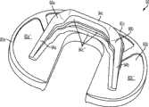
图1-3是根据第一变体的胫骨基部构件的底部轴测图,其采用了一个或多个骨骼内生长或水泥鞘结构和多个突棱部分。1-3 are bottom isometric views of a tibial base component according to a first variation employing one or more bony ingrowth or cement sheath structures and multiple keel portions.
图4-7示出了根据第二变体的胫骨基部构件,其包括用于接收水泥鞘的下侧凹部。4-7 illustrate a tibial base component according to a second variant comprising an inferior recess for receiving a cement sheath.
图8-11示出了根据第三变体的胫骨基部构件。8-11 show a tibial base member according to a third variant.
图12-15示出了根据第四变体的胫骨基部构件。12-15 illustrate a tibial base member according to a fourth variant.
图16-19示出了根据第五变体的胫骨基部构件。16-19 illustrate a tibial base member according to a fifth variant.
图20-23示出了根据第六变体的胫骨基部构件。20-23 illustrate a tibial base member according to a sixth variant.
图24-29示出了根据第七变体的胫骨基部构件,所述基部构件具有前壁部分,前壁部分构造成接触邻近于胫骨前皮层的皮层质骨的外部部分。24-29 illustrate a tibial base member according to a seventh variation having an anterior wall portion configured to contact an outer portion of cortical bone adjacent to the anterior tibial cortex.
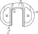
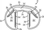
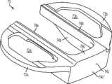
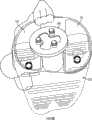
图30-35和47示出了根据第八变体的胫骨基部构件,所述基部构件具有三个突棱部分。30-35 and 47 illustrate a tibial base member according to an eighth variation, said base member having three keel portions.
图36和37示出了根据第九变体的胫骨基部构件,其具有设置在突棱部分上的台阶、纹理或者锯齿状特征。36 and 37 illustrate a tibial base component according to a ninth variation having stepped, textured or serrated features provided on the keel portion.
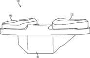
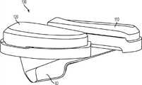
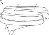
图38-46示出了图30-35和47的胫骨基部构件,示出装配有内侧和外侧关节胫骨插入物。38-46 illustrate the tibial base component of FIGS. 30-35 and 47 shown fitted with medial and lateral articulating tibial inserts.
图48示出用于组装图38-46所示双十字固位胫骨假体的步骤。Figure 48 illustrates the steps used to assemble the double cross-retained tibial prosthesis shown in Figures 38-46.
图49-52是前冠面剖视图,其示意性地示出了根据各种变体的胫骨基部构件和胫骨隆凸之间的匹配几何结构。49-52 are anterior coronal cross-sectional views schematically illustrating mating geometry between the tibial base member and tibial eminence according to various variations.
图53是前冠面视图,双十字固位胫骨假体被示出植入在近侧胫骨上。Figure 53 is an anterior coronal view with the double cross-retained tibial prosthesis shown implanted on the proximal tibia.
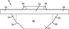
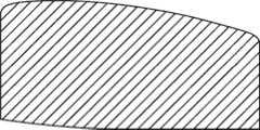
图54和55示出外侧胫骨插入物的后视图。Figures 54 and 55 show posterior views of the lateral tibial insert.
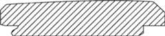
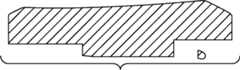
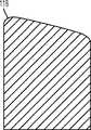
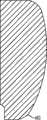
图56示出图54和55的外侧插入物的外侧矢面视图。FIG. 56 shows a lateral sagittal view of the lateral insert of FIGS. 54 and 55 .
图57示出当从前侧边观察时图54-56的外侧插入物的冠面剖视图。Figure 57 shows a coronal cross-sectional view of the lateral insert of Figures 54-56 when viewed from the anterior side.
图58示出当从外侧观察时图54-56的外侧插入物的矢面剖视图。Figure 58 shows a sagittal cross-sectional view of the lateral insert of Figures 54-56 when viewed from the lateral side.
图59和61是内侧胫骨插入物的后视图。Figures 59 and 61 are posterior views of the medial tibial insert.
图60是图59和61的内侧插入物的内侧矢面视图。60 is a medial sagittal view of the medial insert of FIGS. 59 and 61 .
图62示出当从前侧边观察时内侧插入物的冠面剖视图。Figure 62 shows a coronal cross-sectional view of the medial insert when viewed from the anterior side.
图63示出当从内侧观察时内侧插入物的矢面横断剖视图。Figure 63 shows a sagittal cross-sectional view of the medial insert when viewed from the medial side.
图64-66图示出当与图38-46所示双十字固位胫骨假体联合使用时,股骨植入物的一个变体的运动。Figures 64-66 illustrate the motion of a variation of the femoral implant when used in conjunction with the double cross-retained tibial prosthesis shown in Figures 38-46.
图67a-67q示出图64-66对于各种角度弯曲的运动。Figures 67a-67q illustrate the motion of Figures 64-66 for various angles of bending.
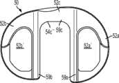
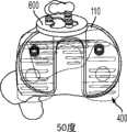
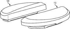
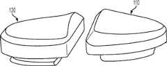
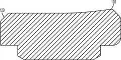
图68是双十字固位膝假体的一个变体的前视图(ACL和PCL保留)。Figure 68 is an anterior view of a variant of the double cross-retained knee prosthesis (ACL and PCL preserved).
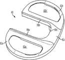
图69是十字固位膝假体的一个变体前视图(PCL保留)。Figure 69 is an anterior view of a variant of a cross-retained knee prosthesis (PCL retained).
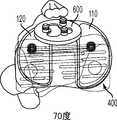
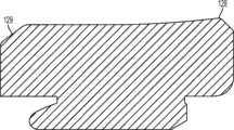
图70和71分别是图68和69的双十字固位和十字固位膝假体的前内视图。Figures 70 and 71 are anteromedial views of the double cruciate-retained and cruciate-retained knee prostheses of Figures 68 and 69, respectively.
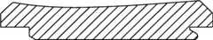
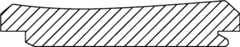
图72和73分别是图68和69的双十字固位和十字固位膝假体的后内视图。Figures 72 and 73 are posterior medial views of the double cross-retained and cross-retained knee prostheses of Figures 68 and 69, respectively.
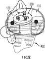
图74和75分别是图68和69的双十字固位和十字固位膝假体的后视图,示出设置于股骨部件的可选的间隙倒角。Figures 74 and 75 are posterior views, respectively, of the double cross-retained and cross-retained knee prostheses of Figures 68 and 69 showing the optional clearance chamfer provided to the femoral component.
图76是根据本发明的一些变体以部分剖面示出可选的后外倒角的内侧股骨髁的上视图。76 is a superior view of the medial femoral condyle in partial section showing an optional posterolateral chamfer according to some variations of the present invention.
图77和78分别是图68和69的双十字固位和十字固位膝假体的外侧矢面视图。Figures 77 and 78 are lateral sagittal views of the double cross-retained and cross-retained knee prostheses of Figures 68 and 69, respectively.
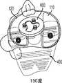
图79和80分别是图68和69的双十字固位和十字固位膝假体的后外侧视图。Figures 79 and 80 are posterolateral views of the double cross-retained and cross-retained knee prostheses of Figures 68 and 69, respectively.
图81是图67a-80中所示股骨部件的上视图。Figure 81 is a superior view of the femoral component shown in Figures 67a-80.
图82-84示出图54-63的内侧和外侧插入物的各种预期视图。82-84 show various contemplated views of the medial and lateral inserts of FIGS. 54-63.
图85示出根据另一变体的双段(bicompartmental)膝植入物,其采用根据一些变体的内侧插入物,其可与内侧单髁胫骨基部构件(未示出)联合使用,且替代地可构造成外侧双段膝植入物(未示出)。85 shows a bicompartmental knee implant according to another variation employing a medial insert according to some variations that may be used in conjunction with a medial unicondylar tibial base component (not shown) and replaces The ground can be configured as a lateral double segment knee implant (not shown).
图86示出根据另一变体的内侧单髁膝植入物,其采用根据一些变体的内侧插入物,并且其可与内侧单髁胫骨基部构件(未示出)联合使用。86 illustrates a medial unicondylar knee implant according to another variation, employing a medial insert according to some variations, and which may be used in conjunction with a medial unicondylar tibial base component (not shown).
图87示出根据另一变体的外侧单髁膝植入物,其采用根据一些变体的外侧插入物,并且其可与外侧单髁胫骨基部构件(未示出)联合使用。87 illustrates a lateral unicondylar knee implant according to another variation, employing a lateral insert according to some variations, and which may be used in conjunction with a lateral unicondylar tibial base component (not shown).
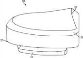
图88示出根据一个变体的单块双十字固位假体,其中,胫骨基部构件包括一体形成的关节表面。Fig. 88 illustrates a monolithic double cross-retained prosthesis according to a variation wherein the tibial base component includes an integrally formed articular surface.
图89示出根据一个变体的单块双十字固位假体,其中,胫骨基部构件是完全或部分地多孔扩增,其包括一体形成的关节表面。Fig. 89 shows a monolithic double cross-retained prosthesis according to a variation wherein the tibial base component is fully or partially porous augmented including an integrally formed articular surface.
图90a-90e示出当从内侧观察时外侧插入物的各种矢面剖视图。Figures 90a-90e show various sagittal cross-sectional views of the lateral insert when viewed from the medial side.
图91a-91k示出当从后侧边观察时外侧插入物的各种冠面剖视图。Figures 91a-91k show various coronal cross-sectional views of the lateral insert when viewed from the posterior side.
图92a-92e示出当从外侧观察时内侧插入物的各种矢面剖视图。Figures 92a-92e show various sagittal cross-sectional views of the medial insert when viewed from the lateral side.
图93a-93m示出当从后侧边观察时内侧插入物的各种冠面剖视图。Figures 93a-93m show various coronal cross-sectional views of the medial insert when viewed from the posterior side.
图94是根据一个变体的股骨部件的内侧矢面视图。94 is a medial sagittal view of a femoral component according to one variation.
图95a-95k分别是沿图94的线A-A到K-K所取的各种冠面剖视图。95a-95k are various coronal cross-sectional views taken along lines A-A to K-K of FIG. 94, respectively.
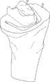
图96是已制备好用于接收图30-35和47的胫骨基部构件的切除过的胫骨的透视图。96 is a perspective view of a resected tibia prepared to receive the tibial base component of FIGS. 30-35 and 47. FIG.
图97-98是根据第十实施例的胫骨基部构件的底部等角视图,其包括一个或多个栓钉。97-98 are bottom isometric views of a tibial base component including one or more pegs, according to a tenth embodiment.
图99是根据一个实施例的外侧插入物的矢面剖视图。Figure 99 is a sagittal cross-sectional view of a lateral insert according to one embodiment.
图100是根据一个实施例的内侧插入物的矢面剖视图。Figure 100 is a sagittal cross-sectional view of a medial insert according to one embodiment.
具体实施方式Detailed ways
以下描述本质上仅是对某些所选变体的示范而非旨在限制本发明、其应用或用途。The following description is merely exemplary in nature of some selected variants and is not intended to limit the invention, its application or uses.
1. 胫骨基部构件1. Tibial base component
图1-46和97-98示出胫骨基部构件的各种非限制性变体,以下讨论它们的一些特征。1-46 and 97-98 illustrate various non-limiting variations of tibial base components, some of their features are discussed below.
图1-3示出第一变体的胫骨基部构件的下侧。通常,基部构件10包括内侧部分12a、外侧部分12b和连接部分12c。在此特定变体中,基部构件10在一些方面上有非对称的形状。例如,如图3中所示,内侧部分12a比外侧部分12b更大并且内侧部分12a的方面相对于外侧部分12b更向前延伸。在其他变体中,所述基部构件可以表现为其他非对称或可以是对称的。1-3 show the underside of the tibial base component of the first variation. Generally, the
图1-3的基部构件10包括在内侧部分12a和外侧部分12b之间形成切去部分8的唇缘15a和15b,其可为保留的胫骨隆凸或其一部分提供间隙。在图1-3中所示的变体中,居中的切去部分8是胫骨内侧-外侧宽度的大约四分之一到三分之一,从而构造成使胫骨隆凸的大部分可以穿过其伸出,但是在一些变体中,可能需要切除所述隆凸的至少前面部分。例如,在一些变体中,胫骨隆凸的前面部分可以与内侧及外侧胫骨切除齐平地切除以给连接部分12c提供空间。为给连接部分12c提供空间而去除的胫骨的量在一些变体中可以是在骨制备之前胫骨隆凸的前到后总尺寸的1/5到1/8范围内。在此特定变体中,连接部分12c设计用于保留并保护ACL附着部位周围的骨骼,并消除应力梯级。The
如图所示,中央切去部分8通常沿胫骨基部构件10的内侧-外侧方向居中,这便于将内侧12a和外侧12b部分的内侧/外侧宽度保持(以及,在一些变体中,与基部构件10相结合使用插入物的内侧/外侧宽度)在大体相同。在其他变体中,不需要内侧12a和外侧12b部分在内侧/外侧尺寸上相同。As shown, the central cut-out 8 is generally centered in the medial-lateral direction of the
图1-3中所述的基部构件10包括从其向远侧延伸的突棱。在一些变体中,此突棱可促进将基部构件固定及固位到患者的胫骨。在一些变体中,此突棱可增加基部构件的强度、扭转刚度及稳定性。在所示的特定变体中,突棱部分14a和16a从基部构件的内侧部分12a延伸,突棱部分14b和16b从外侧部分12b延伸,而突棱部分14c从连接部分12c延伸。The
在一些变体中,突棱部分可以以关于基部构件10的下侧的约90度和约45度之间的角度延伸,不过更大或更小的明显角度也是可能的。在一些变体中,突棱部分可能以相同的一般角度(general angle)远侧延伸或可能以彼此不同的角延伸。在一些变体中,突棱部分可能是彼此对称的,或可能非对称地设置用以适应骨骼解剖学或其他原因。其他基部构件变体(以下讨论)可能具有与图1-3的基部构件10差不多的突棱部分和/或具有不同构造的突棱部分。In some variations, the ridge portion may extend at an angle between about 90 degrees and about 45 degrees relative to the underside of the
在图1-3的特定变体中,尤其如图3中最佳所示,前鳍14c沿内侧-外侧方向转向使得前鳍14c的内侧部分定位得比外侧部分更向前。前鳍14c还沿前/上到后/下方向倾斜,关于此点的部分原因公开于在此说明的后续变体中。前鳍16c还包括远侧的凹口13(见图2)以优化挠性、减少材料、改善应力分布和/或提供更多的旋转稳定性。In a particular variation of FIGS. 1-3 , especially as best shown in FIG. 3 , the
图1-3的基部构件包括从基部构件10的内侧12a和外侧12b部分向远侧延伸的突棱部分16a、16b,其在一些变体中可改善基部构件10的稳定性和/或刚性以抵抗可能施加于其上的力,所述力例如是具有沿前和/或后方向的至少一个分量的力。虽非全部,但在一些变体上可能需要沿前-后方向的加强的稳定性,因为一些股骨部件(比如图67A-D中所示的股骨部件400)在一些情况及用途中可能将这样的力施加到与其一起使用的股骨部件上。在一些变体中,一个或多个突棱部分16a、16b的插入角度和定位可以在空间上优化以获得最好的固定及最好的胫骨安装,以及在骨骼内的前-后和旋转稳定性。除在图中明显示出的这些,其他几何形状的突棱部分16a、16b也可考虑。The base member of FIGS. 1-3 includes
按照一些变体的胫骨基部构件10可以有表面处理,所述表面处理被优化用于与骨水泥或非骨水泥技术一起使用。在一些变体中,基部构件有光滑或抛光的表面,或可以有喷砂表面处理,或其他粗糙表面处理及纹理诸如脊、沟、阶、槽、棘、倒刺,及其组合。内侧部分12a和外侧部分12b的底部或远侧表面还可以包含骨内生长结构,比如带有或不带有羟磷灰石的多孔内生长表面。在一些变体中,可以在基部构件的远侧或下方的下表面上设置一个或多个凹穴以容纳骨水泥技术的水泥鞘。所述一个或多个凹穴可包括用于增加植入物和水泥鞘之间接触表面积的装置,比如网格图样、沟、脊、凹痕、底切(undercuts)、多孔部分、突出物或隆起15c,其可以为该结构的多孔金属材料或表面处理部分。The
图1-3中所示的突棱部分14a、14b、14c、16a和16b分别包括外面表面14a'、14b'、14c'、16a'、16b'及内面表面14a''、14b''、14c''、16a''、16b''。在一些变体中,这些面表面可包括用于改善固定的多孔内生长表面、粗糙表面处理、羟磷灰石或生物特征。在一些变体中,内面表面14a''、14b''、14c''、16a''、16b''和外面表面14a'、14b'、14c'、16a'、16b'可以是相互平行的,或可以相对于彼此以锐角延伸。虽然所示为大体平面,但突棱部分14a、14b、14c、16a、16b的各自面表面14a''、14b''、14c''、16a''、16b''、14a'、14b'、14c'、16a'、16b'可以是更复杂的B样条表面或拱形表面。The
图1-3的基部构件10包括位于前突棱部分14c和内侧突棱部分14a及外侧突棱部分14b之间的融合部(blend)或加强构件18,其在一些变体中可能有助于最小化为容纳植入物而必须去除的骨骼量。例如,在内侧上,加强构件18a的关键的融合部帮助保持突棱部分的底部边缘远离皮质胫骨。以此方式,加强构件18在前突棱部分14c和内侧突棱部分14a之间以及前突棱部分14c和外侧突棱部分14b之间形成过渡区域。The
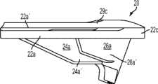
图4-7示出胫骨基部构件的另一个变体-基部构件20。类似图1-3的变体,胫骨基部构件20包括内侧部分22a和外侧部分22b及连接(或前)部分22c,内侧鳍24a从所述内侧部分22a延伸,外侧鳍24b从所述外侧部分22b延伸,前鳍24c从所述连接(或前)部分22c延伸。基部构件20还可包括偏斜的内侧鳍26a和偏斜的外侧鳍26b。类似图1-3的变体,前鳍24c可以包括(图6中所示的)远侧缺口23。基部构件20的上表面可以包括凹部形式的内侧锁定部分22a'和外侧锁定部分22b',所述内侧锁定部分22a'和外侧锁定部分22b'分别构造成接收内侧和外侧插入物。基部构件20还包括用于水泥鞘或可能是多孔长入表面的内侧骨接触面22a''和外侧骨接触面22b''。4-7 illustrate another variation of the tibial base member -
加强构件28a、28b通常是圆柱体形状以利于骨制备。例如,可使用钻头或小直径钻孔器准备骨骼以接收在突棱部分24a、24c和24b之间形成交会的较厚区域。加强构件28a、28b的圆柱形及平滑拱形通常提高了内侧24a和外侧24b部分之间的切去部分的拐角处的强度,所述拐角处在一些变体中可能是高应力区域。The reinforcing
图8-11示出第三变体,胫骨基部构件30,其有与上述基部构件10和20相似的特性。基部构件30包括图8和11中所示的内侧隆凸唇缘39a、外侧隆凸唇缘39b和前隆凸唇缘39c,所述唇缘其可设置在隆凸的切去区域周围以提高基部构件30沿其内边缘的整体强度。在一些变体中该增加的强度对于在其在后部受到负载时抵抗施加在基部构件30上的扭转或其他力可能尤为重要。8-11 illustrate a third variation,
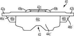
图12-15示出第四变体,基部构件40,其具有与上述基部构件相似的特性而有所变化。例如,如图14中所示,缺口43更为明显。加强构件48a、48b的构造也是不同的,因为如图15中所示,加强构件48a、48b向后延伸并比突棱部分(例如内侧突棱部分44a)沿远侧方向延伸更多。Figures 12-15 show a fourth variant, a
图16-19示出第五变体,基部构件50,其具有与上述基部构件相似的特性而有所变化。例如,如图17中所示,加强构件58a和58b更为明显。另外,如图17中所示,比起其他变体,偏斜的鳍56a和56b关于内侧和外侧部分52a、52b的定位不同。Figures 16-19 show a fifth variation, a
图20-23示出第六变体,基部构件60,其有与上述基部构件相似的特性而有所变化。例如,基部构件60包括内侧鳍64a、前鳍64c和外侧鳍64b,但不包括偏斜的鳍。如图22中所示,前鳍64c包括沟槽或其他表面修饰。基部构件60还包括从基部构件的上表面向近侧延伸的前隆凸唇缘69c(如图22-23中所示)。Figures 20-23 illustrate a sixth variation, a
图24-29示出第七变体,基部构件70,其有与上述基部构件相似的特性而有所变化。基部构架70包括内侧鳍74a、前鳍74c、外侧鳍74b和偏斜的鳍76a、76b,所述偏斜的鳍76a、76b分别从内侧和外侧鳍74a、74b以一个角度延伸。比起其他变体,前鳍74c定位得更向前,以便在其内表面74c''上接合前皮层质骨并安装在邻近于前皮层的外部皮层质骨表面上。基部构件70包括图26和29中所示的内侧隆凸唇缘79a、外侧隆凸唇缘79b和前隆凸唇缘79c,其可沿隆凸切去区域的内侧和外侧设置以提高基部构件70沿内边缘的整体强度。Figures 24-29 show a seventh variant, a
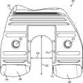
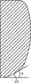
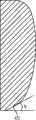
图30-35及47示出第八变体,基部构件80具有三个突棱部分-内侧突棱部分84a、前突棱部分84c和外侧突棱部分84b。图96示出已制备好用于接收基部构件80的切除过的胫骨220。如图96中所示,胫骨隆凸222是未经触动的。如图35中所示,前突棱部分84c比内侧和外侧突棱部分84a、84b更进一步地向远侧延伸,这在一些变体中可能会强化固定。另外,与前面的一些变体一样,前突棱部分84c是倾斜的并在相对于胫骨切除平面和/或前部82c的下侧沿上-前到下-后方向延伸(见图35),这在一些变体中可能有助于增加突棱部分的深度以便获得强度和固定性而不会不利地干扰胫骨的前皮层,并且在一些变体中,不需要将连接部分82c向后放置得那么远以至其可能干扰隆凸上的ACL附着部位。在一些变体中,前突棱部分84c的倾斜有助于在插入及嵌塞期间防止近侧胫骨的前皮层质骨的刺穿,或近侧胫骨的劈裂或破裂。在一些变体中,前突棱部分64c的倾斜增加了前鳍84c和前胫骨皮层质骨之间保留的骨骼量。在此特定变体中,前突棱部分82c的内表面84c''和基部构件80的骨接触下表面82a''、82b''之间的角度α在约50度和约90度之间,更优选在约65度和约75度之间,例如约70度。在一些变体中,内侧突棱部分84a和外侧突棱部分84b还在一些方面例如这些突棱部分的顶表面上以下-后角度延伸。Figures 30-35 and 47 illustrate an eighth variation in which the
如图35最佳所示,在一些变体中,前连接部分84c的后面(其邻近于唇缘89c)和前突棱部分84c的后侧84c''可能不在近侧胫骨切除平面的水平上相交,从而,在一些变体中,帮助避免在前突棱部分的制备期间削弱胫骨隆凸前部或造成骨折。换而言之,这两个表面的相交处偏离预定距离(图35中所示的r)以确保前突棱部分82c的骨制备不危及被保留的隆凸。As best shown in FIG. 35, in some variations, the posterior side of the anterior connecting
又如图34和35中所示,在此特定变体中,前连接部分82c的唇缘89c和基部构件80的骨接触下表面82a''、82b''之间的角度θ处于约60和约90度之间,更优选地在约82和约88度之间,例如约85度。此角度有效地形成底切以在已制备好的前隆凸的前基部部分处增加保留骨的数量并从而降低骨应力。换而言之,在一些变体中,隆凸的前切是渐细的,使隆凸的基部面积比其近侧面积更大,这改善了隆凸222的拉脱强度。由角度θ形成的底切还可以允许骨水泥、腻子或其他生物材料易于流动到隆凸222的前基部区域从而加强和填充可能位于前隆凸的基部的拐角处的应力梯级,在该拐角处,前隆凸骨切与近侧胫骨切除相遇。设置或塞入到在骨骼和胫骨基部构件80之间的底切角度θ内或其周围的材料也可能压制曾经植入的骨骼部分,防止胫骨基部构件80的微运动并避免下沉。如前所述,可以改变上述角度和其他几何特征以最佳地适应患者独特的解剖结构。34 and 35, in this particular variation, the angle θ between the
如图30中最佳所示,该特定变体的前鳍84c和内侧部分82a内部之间的角γ在约75度和约90度之间,并更优选为在约82度和约88度之间,例如约85.5度。尤其如图32中最佳所示,在该特定变体中,前连接部分82c和外侧部分82b内部之间的角β在约90度和约120度之间,并更优选为在约92度和约98度之间,例如约95度。换而言之,内侧和外侧部分82a和82b之间的切去部分的前边缘是倾斜的,使得连接部分82c的内侧比连接部分82c的外侧更向前。在该特定实施例中,基部构件80的切去部分的前内侧上的额外的前空间为ACL提供更好的间隙,所述间隙在ACL附着区域的内侧上一般位于更向前处。连接部分82c的更靠后定位的外侧还避免干扰ACL的后外侧束(bundle)的附着,并在外侧上提供更多材料以改善非对称设计的强度。对于定制或患者特定的胫骨基部构件,可以改变上述角度和其他几何特征以最佳地适应患者独特的解剖结构。可以进行这样的改变以在骨骼保留和强度之间满足适当的平衡。As best shown in FIG. 30, the angle γ between the
在图30-35及47所示的变体中,突棱部分84a、84b、84c随着其接近与其他突棱部分的交点而变宽或变粗。在一些变体中,比如图30-35的变体中,由于基部构件80的顶表面和内侧表面部分从材料厚度受限的内侧82a和外侧82b过渡到前部82c,加强构件88a、88b在基部构件80的前部82c的那侧上的这些融合部及过渡减少了应力梯级,从而保留了最小的胫骨插入物厚度并允许插入物从所述的前边滑入并接合锁定部分82a',82b'。In the variation shown in Figures 30-35 and 47, the
如图35中最佳所示,内侧和外侧突棱部分84a和84b的上-下高度通常可以向后减小以在一些变体中提供优化的应力分布和足够的挠性以防止应力遮蔽。而且,突棱部分84a、84b、84c大致沿前-后方向倾斜以提供对胫骨基部构件80的内侧和外侧部分82a和82b的支持。至少在一些变体中,突棱部分84a、84b、84c沿前-后和内侧-外侧两个方向的角度和位置在以下两者之间提供至少一定程度的平衡:(a)在基部构件80的后部负载期间支撑基部构件80的每边部分82a、82b的中央部分;以及(b)在基部构件80的内侧或外侧处的极端边缘负载期间支撑基部构件80的内侧和外侧部分82a、82b的边缘部分。另外,可设计突棱部分84a、84b、84c的角度和位置以支撑这样的负载而不需要相当宽的前突棱部分84c,否则所述前突棱部分84c若做得太宽可能会干扰或突起穿过胫骨220的前皮层。虽然图示示出倾斜的侧突棱部分84a、84b的下边缘是直边缘,但在其他实施例中,其远侧边缘的形状也可以是弯曲或有台阶的以使得内侧和外侧突棱部分84a、84b的深度变化是关于后部距离的非线性函数。侧突棱部分84a、84b的弯曲或有台阶的下边缘(例如图7变体中所示)可允许胫骨基部构件80内的应力分布的更佳优化。As best shown in FIG. 35 , the superior-inferior heights of the medial and
在一些变体中,例如在图30-35及47所示的变体中,内侧和外侧突棱部分84a、84b可以有将外围水泥轨87a、87b连接到突棱部分84a、84b的一个或多个加强腹板85a、85b(图34-35)。可关键性地设置加强腹板85a、85b以在任何高应力点下通过,比如在锁定部分82a',82b'的转角处(图32-33),其可以是,例如,位于内侧和外侧部分82a和84a近侧边上并构造成接收内侧和外侧胫骨插入物110、120(以下讨论)的切去凹部或凹穴。虽然没有示出,但只要胫骨插入物110、120的下边也设置有互补的凹部以给腹板85a、85b提供间隙,腹板85a、85b也可以设置在锁定部分82a',82b'的顶凹穴部分内。In some variations, such as those shown in FIGS. 30-35 and 47, the inner and
如图34中所示,可在胫骨基部构件80的隆凸唇缘部分89a、89b、89c之间设置圆转角、倒圆或内圆角81a、81b以形成构造成容纳胫骨隆凸的切去部分的内表面。在一些变体中,所述圆转角、倒圆或内圆角81a、81b可以减少在这些区域的应力梯级从而克服与现有双十字韧带固位设计典型的锐利转角相关的断裂。在一些变体中,所述转角的倒圆的量可以避免在胫骨220上的植入物和前十字韧带附着部位之间产生干扰。As shown in FIG. 34, rounded corners, rounds or
而且,与其他变体一样,可设置沿隆凸切去区域的内侧和外侧的加高的壁或隆凸唇缘部分89a、89b、89c(见例如图33)以提高基部构件80沿内部边缘的整体强度。当在后部加载时,该增加的强度在至少一些变体中可促使抵抗基部构件80上的应力或其他力。另外,隆凸唇缘部分89a、89b、89c,当与下表面82a''、82b''组合时,可促使为水泥鞘形成更大的边界并允许水泥鞘沿已制备好的胫骨隆凸基部生长。沿基部转角和胫骨隆凸的侧面并且在此隆凸和基部构件80之间的该额外的水泥通常会改善对隆凸骨折的抗性。加高的壁或隆凸唇缘部分89a、89b、89c可以进一步用于将胫骨插入物从已制备好的胫骨隆凸的水泥鞘和竖直壁隔离开,还用于沿内侧-外侧方向稳定胫骨插入物的扶壁(buttress)。Also, as with other variations, raised wall or raised
前连接部分82c可以在矢面截面(例见图35)及在上方观察时(例见图33)限定大体梯形的矢面形状。在此变体中,前部82c向后渐宽(内侧-外侧方向)。这样的几何形状在一些变体中可能有助于在前部82c中限制应力集中,并通过鼓励应力更向前流动到较少应力梯级的区域而促进更均匀的应力分布。The anterior connecting
在此特定变体中,胫骨基部构件80的前连接部分82c是倾斜的以向后渐厚(上-下尺寸),这在一些变体中可能在接近隆凸切去边缘处提高基部构件80的强度,同时仍在基部构件80的前面部分上提供更大的挠性,以当基部构件80受到后部负载时有均匀的应力分布。例如,如果内侧部分82a或外侧部分82b之一比起其他受到更多后部负载(例如在深度挠曲时),则前面部分82c内的扭力可能上升。在这样的情况下,前面部分82c较薄的前部所形成的挠性更均匀地分布扭转应力,而前面部分82c的较厚的后部和凸出的前隆凸唇缘89c则提供额外的强度和刚性。In this particular variation, the anterior connecting
图41示出胫骨基部构件80,胫骨插入物110和120安装于其上。如图41中所示,从前面部分82c较厚唇缘部分89c到较凹的内侧和外侧隆凸唇缘89a和89b的过渡在基部构件80的隆凸切去部分转角处高应力区域提供更多的材料。因此,内侧和外侧唇缘89a和89b会比前面部分82c及前隆凸唇缘89c更短而不对胫骨基部构件80的强度产生不利影响。另外,降低内侧和外侧唇缘89a和89b的高度能够防止唇缘89a、89b的顶部与股骨部件400接触,尤其是在使用薄的聚合物插入物110、120的情况下。Figure 41 shows the
回到图32-33,胫骨基部构件80的上或近侧可以包括内侧平台锁定部分82a'和外侧平台锁定部分82b',所述锁定部分82b'每个都具有用于固定聚合物胫骨插入物的锁定细节。这样的锁定细节可以包括,例如,一个或多个底切,鸠尾接合,凸凹连接,沟槽,脊,压配连接,倒钩,闩锁,栓钉,磁体,以及其它本领域已知的连接装置。如下将讨论的,为了移动支承应用,锁定细节可以允许插入物和缓的旋转或平移运动。图38-46示出组装有内侧关节插入物110及外侧关节插入物120的胫骨基部构件80。在一些变体中,胫骨基部构件80和/或胫骨插入物110、120的外围与所切除胫骨近侧严格对齐。32-33, the upper or proximal side of the
虽未示出,但胫骨基部构件80的上表面可以构造成与移动支承一起使用。换而言之,在某些变体中,内侧和外侧锁定部分可以设置有用于将内侧和外侧插入物固定到基部构件,同时允许插入物的一些有限旋转运动的装置。这样的装置可包括,例如,凸形到凹形的连接(比如孔内的栓钉构造)或在将插入物锁定在5度自由范围内的圆形底切,同时仍允许插入物能够相对于基部构件受控旋转。也可提供其他装置,比如允许插入物在前-后和内侧-外侧方向之任一个或多个上受控平移的轨道或随动件。Although not shown, the upper surface of the
图36-37示出胫骨基部板的第九变体,胫骨基部板90。与这里描述的一些更早的变体一样,胫骨基部板90包括后掠的突棱部分。在此特定变体中,突棱部分94a、94b、94c是有台阶的,以在植入插入物期间提高骨挤压并在台阶转角处形成应力增高区域。对于骨水泥和非骨水泥应用,具有带台阶的突棱部分94a、94b、94c的基部构件90还可以促进更好的固定。在一些变体中,用于制备胫骨以接收胫骨基部构件的设施可以包括具有台阶或没有台阶的冲孔器以提供更多或更少的干涉和压配合接合。36-37 illustrate a ninth variation of a tibial base plate,
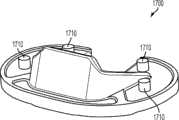
图97-98示出胫骨基部板的第十变体,胫骨基部板1700。与这里所描述的一些更早的变体一样,此胫骨基部板1700包括后掠的突棱部分。此特定变体还包括栓钉1710或其他合适的结构用于给已制备好的胫骨220提供增强的固定。97-98 illustrate a tenth variation of a tibial base plate,
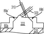
图49-52是前冠面剖视图,示出在胫骨基部构件80a-80d之间匹配的几何形状,这样的基部构件分别有内侧隆凸唇缘89a-89a''''和外侧隆凸唇缘89b'-89b'''',以及已制备好的胫骨220的胫骨隆凸222。如图中所示,前十字韧带(ACL)310和后十字韧带(PLC)320之一或两者都被保留。图53是关于已制备好的胫骨220和胫骨隆凸222的组装有插入物110、120的胫骨基部构件80的正冠面视图。49-52 are anterior coronal cross-sectional views showing mating geometry between
在一些变体中,可以根据收集到的数据优化相关的前突棱部分的长度和角度。已知给定前突棱部分的长度,提高前突棱部分偏离竖向的角度通常就提高前突棱部分底切前胫骨隆凸的量,而且太大的角度会降低基部构件的强度。如果前突棱部分底切隆凸太多,所述隆凸也会被削弱。胫骨基部构件的一些变体是通过以下组合实现的:优化外形的组合将应力更有效地分布在整个基部构件上,通过分析已知断裂的以前的胫骨基部构件设计而改进目标强度,并以迭代方式运行计算机仿真。尸体实验期间所接收的输入被用于识别从解剖学观点来说可接收的骨移除的量和面积,且这样的信息还用于确定突棱部分的优化值、几何结构和朝向,用以在各种变体中提高强度并改善初始固定。为了提高设计的健壮性而不论材料的强度和性质,发明人考虑了使用具有高和低疲劳抗性的各种材料制造相同的基部构件设计。In some variations, the length and angle of the associated anterior keel portion can be optimized based on the collected data. Given the length of the anterior keel portion, increasing the angle of the anterior keel portion from vertical generally increases the amount by which the anterior keel portion undercuts the anterior tibial eminence, and that too large an angle reduces the strength of the base member. The keel can also be weakened if the anterior keel portion undercuts the keel too much. Some variations of the tibial base component have been achieved through a combination of optimized shapes to distribute stress more efficiently across the base component, target strength improvements through analysis of previous tibial base component designs with known fractures, and iterative run computer simulations. Input received during cadaveric testing was used to identify anatomically acceptable amounts and areas of bone removal, and such information was also used to determine optimal values, geometry, and orientation of the keel portion for Increases strength and improves initial fixation in various variants. In order to increase the robustness of the design regardless of the strength and properties of the material, the inventors considered manufacturing the same base member design using various materials with high and low fatigue resistance.
所选的整个突棱的特定形状和前突棱部分的角度组合实质上形成“自锚固”特性,所述角度在一些变体中为约70度。换而言之,由于前突棱部分底切松质骨(相对于近侧胫骨平台),就提供了压制力以对抗拔出力。The particular shape of the overall keel selected in combination with the angle of the anterior keel portion, which in some variations is about 70 degrees, essentially creates a "self-anchoring" characteristic. In other words, since the anterior ridge partially undercuts the cancellous bone (relative to the proximal tibial plateau), a compressive force is provided to resist the pull-out force.
还公开了植入胫骨假体的方法。所述方法包括以下步骤:确定切除深度;为假体确定优选空间朝向;切除内侧和外侧胫骨平台的骨部分而不牺牲胫骨隆凸及附着到它的ACL/PCL;钻出必要的接收部分用以接收设置在所述胫骨假体的下侧上的一个或多个固位零件;以及使用骨水泥或非骨水泥技术安装胫骨假体。A method of implanting a tibial prosthesis is also disclosed. The method comprises the steps of: determining the depth of resection; determining a preferred spatial orientation for the prosthesis; resecting the bony portion of the medial and lateral tibial plateau without sacrificing the tibial eminence and the ACL/PCL attached to it; to receive one or more retention features disposed on the underside of the tibial prosthesis; and installing the tibial prosthesis using cemented or non-cemented techniques.
2. 胫骨插入物2. Tibial Insert
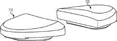
上述及其他的变体提供改进的胫骨插入物,诸如图38-44中所示的与基部构件80组装在一起的内侧插入物110和外侧插入物120。在一些变体中,内侧插入物110比外侧插入物120更薄以便匹配出现在股骨部件上的内翻关节线。比如,在一些变体中,外侧插入物120可能比内侧插入物120厚大约2.5 mm,从而形成与股骨部件的3°内翻关节线匹配的3°内翻关节线。一些变体的胫骨关节几何结构通常包括在内侧插入物110上的凹内侧部分及外侧插入物120上的凸外侧部分。在插入物110、120之一或两者的内部部分上可以表现出冠面顺应性。此冠面顺应性例如可包括中唇缘,所述中唇缘如下面所详述地可沿前-后方向变化高度。The above and other variations provide improved tibial inserts, such as the
图54-58示出外侧插入物120变体的各种视图,而图59-63示出内侧插入物110变体的各种视图。54-58 show various views of
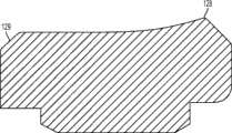
图54-58的外侧插入物120限定了上关节面,在各平面中限定几个不同轮廓。图57和58是某些冠平面(图57)和矢平面(图58)内的外侧插入物120的截面。图57示出由外侧插入物120相对靠前的冠面截面所限定的轮廓126a。图58示出由外侧插入物120相对居中的矢面截面所限定的轮廓124b。图90a-e是左外侧插入物的一个变体的一系列矢面截面,示出该插入物从插入物的相对中部(例如图90a)到相对外部(例如图90e)的轮廓。图91a-k是与如图90a-e中所示相同的变体的一系列截面,图91a-k的冠面截面从插入物的相对前部(例如图91a)到相对后部(例如图91k)前进。The
如图54-58和90-91的变体中所示,并如以下所详述,外侧插入物120限定中唇缘128和环形倒角129。在一些变体中,外侧插入物120的前部和轮廓的至少一些部分比起插入物120的其他部分来说与股骨髁表面相对更一致。如图56中所示,外侧插入物120还可以包括外围台阶127a、127b。图56和58示出用于将外侧插入物120固定到胫骨基部构件的锁定机构122。As shown in the variations of FIGS. 54-58 and 90-91 , and as described in detail below, the
如图54-58和90-91的变体中所示,中唇缘128相对于插入物120的其他部分及轮廓被抬高。如图58中所示,被抬高的中唇缘128从插入物120的前部到后部延伸,其中,图58示出穿过插入物120的中间部分的插入物120的矢面截面。在一些变体中,中唇缘128对外侧股骨平移提供抗力并阻止股骨部件400和胫骨隆凸222之间的冲撞。可以选择中唇缘的高度以提供需要的抗力水平,高度越高提供的抗力越强。如这些变体中所示,随着中唇缘沿前到后方向延伸,其相对于插入物120的其他部分的高度逐渐下降。在图54-58及90-91的变体中,外侧插入物120的外边部分(接近倒角129)基本是平的并且与股骨髁关节表面的冠面顺应性很小甚至没有。在一些变体中,相对于大体平坦的外边部分,中唇缘128的最大高度在约0.025英寸和约0.125英寸的范围之间。在一些变体中,对于外侧插入物,中唇缘128的最大高度在约0.035英寸和约0.065英寸之间。As shown in the variations of Figures 54-58 and 90-91, the
图59-63示出内侧插入物110的变体,其限定了上关节表面,在各平面中限定几个不同轮廓。例如,图62示出在插入物110相对中部处所取的内侧插入物110的冠面截面,示出冠面轮廓116a。图63示出在插入物110相对中部处所取的内侧插入物110的矢面截面,示出轮廓114b。图92a-e是左内侧插入物的一个变体的一系列矢面截面,示出该插入物从插入物的相对中部(例如图92a)到相对外部(例如图92e)的轮廓。图93a-m是与图92a-e中所示相同的变体的冠面截面,图93a-m的冠面截面从插入物的相对前部(例如图93a)到相对后部(例如图93m)前进。Figures 59-63 illustrate a variation of the
类似外侧插入物,内侧插入物110还包括中唇缘118和环状倒角119(例如图60)。在一些变体中,插入物110的前、中部比插入物的其他部分与相关的股骨部件更一致。如图60中所示,内侧插入物110还包括外围台阶117a、117b。图61和63示出用于将内侧插入物110固定到胫骨基部构件的锁定机构112。Like the lateral insert, the
如图62-63及92-93中所示,中唇缘118相对于插入物的其他部分和轮廓被抬高。如图63中所示,被抬高的中唇缘118从插入物110的前部到后部延伸,其中,图63示出穿过插入物110的中间部分的插入物110的矢面截面。在一些变体中,中唇缘118对外侧股骨平移提供抗力并阻止股骨部件400和胫骨隆凸222之间的冲撞。可以选择中唇缘的高度以提供需要的抗力水平,高度越高提供的抗力越强。如这些变体中所示,随着中唇缘沿前到后方向延伸,其相对于插入物110的其他部分的高度逐渐下降。在图62-63和92-93的变体中,内侧插入物110的外边部分(接近倒角119)基本是平的并且与股骨髁关节表面的冠面顺应性很小甚至没有。在一些变体中,相对于大体平坦的外边部分,中唇缘118的最大高度在约0.025英寸和约0.115英寸的范围之间。在一些变体中,对于内侧插入物,中唇缘118的最大高度在约0.035英寸和约0.065英寸之间。As shown in Figures 62-63 and 92-93, the
图64-67图形地且形象地示出在某些关节成形术过程中图54-63的内侧和外侧插入物110、120当与其他部件(比如股骨部件400和膝盖骨部件600)一起使用时的运动学特性。使用LifeMODTM计算机仿真,发明人已确定在内侧胫骨插入物110上设置中唇缘118起到防止股骨部件400响应外侧力而外侧地平移的作用,所述外侧力因四头肌的角度或“Q角”而由膝盖骨施加到股骨部件400。在一些变体中,没有中唇缘118的情况下,由于膝盖骨的切力,股骨部件400会变为外侧地弯曲,造成内侧髁408移动到距后十字韧带320的附着部位和周边骨220、222太近的情况。除了提高超越当前工艺设计的假体的整体性能,在一些变体中,抬高的中唇缘118还在伸腿时提供更多的胫骨-股骨接触。在一些变体中,内侧插入物110将包括中唇缘118而外侧插入物120不包括中唇缘128,但中唇缘118、128都可加到两个插入物110、120以得到更高的稳定性。64-67 graphically and graphically illustrate the medial and
图64-66图解地示出股骨植入物400在与图38-46的变体中所示植入物100一起使用时各自的内侧股骨回卷(rollback),外侧股骨回卷及外部股骨旋转。在一些变体中这可能与至少一些以前的双十字固位设计相反,所述以前的设计在邻近股骨部件朝向胫骨插入物中线及外围边缘的区域内采用过度地顺应的冠面轮廓。在一些现有技术设计中表现出的这种过度顺应性负面地约束股骨部件的内部-外部旋转并降低或消除内侧-外侧平移。至少一些已知的设计还在插入物的前和后部分处表现出高度的顺应性,这在膝伸展及弯曲期间负面地限制股骨旋转。在此特定变体中,图68中所示的设计,通常只提供朝向胫骨中线的冠面顺应性,所述冠面顺应性向着插入物的后边缘逐渐下降。由于这种顺应性上的降低,该特定设计更自由地允许股骨部件400的内部和外部旋转并在弯曲时更准确地复制正常的膝运动,其中,股骨部件400相对于胫骨假体100外部旋转。不过,其他变体可以类似于其他现有技术设计展现高度地顺应的插入物。Figures 64-66 diagrammatically show the respective medial femoral rollback (rollback) of the
在一些情况下,可以给胫骨插入物110和/或120提供多个不同后斜角度选择。在一个变体中,比如110和/或120的插入物可以以不同的量向后变薄以便相对插入物110、120下表面有效地旋转关节表面屈-伸角度,并提供更大的后斜度。这样的选择在一些变体中可允许外科医生在膝弯曲时选择性地调整关节松弛度。例如,可提供几对内侧和外侧插入物110和120,每对在后斜度上都与其他对相差在约1-4度之间的指定度数,例如2度。其他选择可包括配对内侧和外侧插入物110和120,其中,内侧插入物110的后斜度不同于外侧插入物120的后斜度。这样的选择通常可允许在无需重切胫骨骨骼220的情况下调节弯曲空间。还针对上面提到的选择为每个内侧和外侧插入物110和120提供多厚度选择,以提供适当的韧带平衡。可采用插入物厚度、内侧-外侧斜度和前-后斜度的各种组合及构造以适合个别患者的特定解剖需要。也可以在胫骨基部板内构造多厚度、内侧-外侧斜度和前-后斜度的选择以在使用单一插入物时提供这些构造。In some cases, tibial inserts 110 and/or 120 may be provided with a choice of multiple different posterior slope angles. In a variation, inserts such as 110 and/or 120 may be thinned posteriorly by different amounts to effectively rotate the articular surface flexion-extension relative to the lower surface of
在一些变体中,可以通过单个包含十字的插入物500提供内侧和外侧插入物110和120的关节几何结构,如图69、71、73、75、78及80中所示,所述插入物包括凹内侧和外侧关节表面。如图80中所示,插入物500的外侧部分510可以比内侧部分更厚(在一些变体中,厚出约2.5 mm)以允许所示股骨部件400的功能。在此特定变体中,该较厚的外侧部分510用于匹配出现在股骨部件400上的内翻关节线。In some variations, the articulation geometry of the medial and
在其他变体中,可以设置各有不同的后斜角度或厚度,并可以各种组合利用的内侧和外侧插入物110和120以应对不同的内侧和外侧副韧带平衡需求。在一些实例中,可以在外科手术植入物套装中提供包括多个尺寸的一套插入物110、120,其中,特定的插入物110、120的底部平面和其相应的关节表面之间的一般角度在插入物之间变化。该角度可以在前-后方向及内侧-外侧方向之一或两者上独立或共同地增加或减少。提供多个后斜度选择可以有利地降低再切削胫骨220的需求。In other variations, the medial and
图56和68示出凸外侧插入物120的示例,所述插入物有助于股骨部件400在弯曲期间以及通过外侧股骨回卷的外部旋转,同时内侧股骨髁408被如一些变体所提供的内侧插入物110的矢面凹几何形状所约束。56 and 68 show an example of a convex
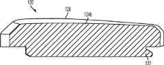
作为使用分离的胫骨插入物110、120的另一种选择,图88中所示的胫骨基部构件1500可以包括整体成型的单块关节表面。其他变体,例如图89中所示,可包括带有关节表面1604的由多孔结构材料比如金属泡沫形成的胫骨假体1600,所述关节表面1604如图89中所示模块化或整体化设置在多孔结构1602近侧区域。例如,关节表面1604可形成为位于多孔结构近侧上的实心金属、陶瓷、聚合物、涂层或柔顺材料。这可以通过使用常规的快速制造技术实现,比如选择性激光烧结(SLS),电子束焊(EBM),3D打印,或立体光刻。替代地,多孔结构1602可使用聚合物包覆模塑以形成单块基部构件1600,所述基部构件具有多孔结构1602和不同材料的关节表面1604。As an alternative to using separate tibial inserts 110, 120, the
3. 股骨部件3. Femoral component
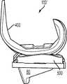
还提供改进的股骨部件。例如,图67-75中所示的股骨部件400包括内侧髁408和外侧后髁406,外侧后髁406包括后外侧倒角404(例见图68-69、72-74)。如图74-75中所示,在一些变体中,后外侧倒角404有深度或距离d和角度Φ以产生与后外侧组织(例如深屈膝时的腘肌腱)的间隙,所述d在约1和约5 mm之间,更优选地在约2和约4 mm之间,例如约2.8 mm,所述Φ在约0和约25度之间,更优选地在约5和约15度之间,例如约10度。倒角404可以产生从近侧骨骼接合表面的距离D,所述表面构造成与远侧股骨骨切相配合,所述距离D例如在约3和约20 mm之间,更优选地在约8和约15 mm之间,例如约11 mm。随着股骨部件400尺寸的增加,距离d和D可成比例或不成比例地增加。在一些变体中,例如,较大尺寸的股骨部件400可采用约10°的角度Φ和约11 mm的距离D,而较小尺寸的股骨部件400则可以采用约10 mm的较小距离D。Improved femoral components are also provided. For example, the
类似地,内侧后髁408可在其内表面上包括图74、76、79-81中所示的后外侧倒角410,所述倒角有角度ψ,所述角度ψ在约0和约10度之间并更优选为在约3和约7度之间,例如图74中所示的约5度。这样的倒角可与另一倒角470组合以提供关于胫骨隆凸222和后十字韧带320的额外的间隙而不减少骨覆盖范围,所述另一倒角470可掠过后内侧髁408的内矢面圆角周围。在一些变体中,后倒角470恰在股骨部件400的髌骨接触区域412之后开始,因此,其不会掠过股骨部件的髁间髌骨接触区域412。更确切地说,后外侧倒角470在内侧股骨髁408的后部内可更明显。胫骨隆凸222的上边缘也可以使用咬骨钳来倒角以进一步避免与股骨部件400的碰撞。Similarly, the
图94是根据一个方面的股骨部件450的内侧髁445的内侧矢面视图。内侧后髁445可在其内表面上包括后外侧倒角470。图95a-95k分别是示出后外侧倒角470的图94沿线A-A到K-K所取的各种冠面剖视图。如图95a-95k中所示,当沿线A-A、J-J和K-K看时,股骨部件包括圆边缘460,而当沿线B-B、C-C、D-D、E-E、F-F、G-G、H-H、I-I看时,股骨部件包括后外倒角470。在一些变体中,后外倒角470的角度ψ在约15和约40度之间。94 is a medial sagittal view of the medial condyle 445 of the
如图68中所示,股骨部件400的前凸缘可以在外侧和/或内侧上包括前外侧倒角402以降低韧带组织上的张力,其可能常见于一些现有技术的股骨设计中。As shown in FIG. 68, the anterior flange of the
在不背离本发明范围的情况下,对于如上参照相应图示说明示范的变体可进行各种修改,因此所意图的是,前述说明和附图中所示的所有内容都应被理解为说明性的而非限制性的。例如,所公开的胫骨插入物的新颖特征可易于应用于例如胫骨插入物试验的设施,以及设计为要植入的植入物。因此,本发明的广度和范围不应被上述示范变体的任一个所限制,而是代以只根据这里所附的任意权利要求及其等同物所限制。另外,可以预期本领域技术人员可以以任何兼容的组合或排列方式来使用以上变体所公开的任何或全部特征。Various modifications may be made to the variants which have been exemplified above with reference to the corresponding drawings without departing from the scope of the invention, and it is therefore intended that all that is shown in the foregoing description and drawings should be understood as illustrative. sexual rather than restrictive. For example, the novel features of the disclosed tibial inserts are readily applicable to facilities such as tibial insert trials, as well as implants designed to be implanted. Thus, the breadth and scope of the present invention should not be limited by any of the above-described exemplary variations, but should instead be limited only in accordance with any claims appended hereto and their equivalents. In addition, it is contemplated that those skilled in the art may use any or all of the features disclosed in the above variants in any compatible combination or permutation.
Claims (18)
Applications Claiming Priority (10)
| Application Number | Priority Date | Filing Date | Title |
|---|---|---|---|
| US29983510P | 2010-01-29 | 2010-01-29 | |
| US61/299,835 | 2010-01-29 | ||
| US61/299835 | 2010-01-29 | ||
| US37255610P | 2010-08-11 | 2010-08-11 | |
| US61/372556 | 2010-08-11 | ||
| US61/372,556 | 2010-08-11 | ||
| US38228710P | 2010-09-13 | 2010-09-13 | |
| US61/382,287 | 2010-09-13 | ||
| US61/382287 | 2010-09-13 | ||
| PCT/US2011/022922WO2011094540A2 (en) | 2010-01-29 | 2011-01-28 | Cruciate-retaining knee prosthesis |
Publications (2)
| Publication Number | Publication Date |
|---|---|
| CN102821717Atrue CN102821717A (en) | 2012-12-12 |
| CN102821717B CN102821717B (en) | 2016-01-20 |
Family
ID=44320150
Family Applications (1)
| Application Number | Title | Priority Date | Filing Date |
|---|---|---|---|
| CN201180016702.3AActiveCN102821717B (en) | 2010-01-29 | 2011-01-28 | Cross maintenance knee prostheses |
Country Status (12)
| Country | Link |
|---|---|
| US (9) | US8900316B2 (en) |
| EP (2) | EP2528546B1 (en) |
| JP (3) | JP6161900B2 (en) |
| KR (1) | KR101902350B1 (en) |
| CN (1) | CN102821717B (en) |
| AU (3) | AU2016213861A1 (en) |
| BR (1) | BR112012019029A2 (en) |
| CA (1) | CA2788462C (en) |
| ES (1) | ES2695400T3 (en) |
| IN (1) | IN2012DN06596A (en) |
| TR (1) | TR201815901T4 (en) |
| WO (1) | WO2011094540A2 (en) |
Cited By (5)
| Publication number | Priority date | Publication date | Assignee | Title |
|---|---|---|---|---|
| CN104968301A (en)* | 2013-02-07 | 2015-10-07 | 捷迈有限公司 | Tapered tibial augment |
| CN109982664A (en)* | 2016-11-24 | 2019-07-05 | 沃尔德马连接两合公司 | Intermediate segment for joint components |
| CN110538005A (en)* | 2019-08-05 | 2019-12-06 | 沈计荣 | Spacer structure and prosthetic component therewith |
| CN113631122A (en)* | 2019-02-28 | 2021-11-09 | 丽玛共同股份公司 | Tibial baseplate for tibial component of knee prosthesis (tibial component including tibial baseplate) and method of manufacturing tibial baseplate |
| CN114176847A (en)* | 2022-01-12 | 2022-03-15 | 雅博尼西医疗科技(苏州)有限公司 | Tibia support with reinforcing structure |
Families Citing this family (89)
| Publication number | Priority date | Publication date | Assignee | Title |
|---|---|---|---|---|
| US9603711B2 (en) | 2001-05-25 | 2017-03-28 | Conformis, Inc. | Patient-adapted and improved articular implants, designs and related guide tools |
| US8480754B2 (en) | 2001-05-25 | 2013-07-09 | Conformis, Inc. | Patient-adapted and improved articular implants, designs and related guide tools |
| WO2009158318A1 (en) | 2008-06-27 | 2009-12-30 | Zimmer, Inc. | Acl accommodating tibial design |
| CA2782137A1 (en) | 2009-12-11 | 2011-06-16 | Conformis, Inc. | Patient-specific and patient-engineered orthopedic implants |
| US8900316B2 (en) | 2010-01-29 | 2014-12-02 | Smith & Nephew, Inc. | Cruciate-retaining knee prosthesis |
| ES2632995T3 (en) | 2010-07-24 | 2017-09-18 | Zimmer, Inc. | Asymmetric tibia components for a knee prosthesis |
| US8591594B2 (en) | 2010-09-10 | 2013-11-26 | Zimmer, Inc. | Motion facilitating tibial components for a knee prosthesis |
| WO2012058540A1 (en)* | 2010-10-28 | 2012-05-03 | Jerry Gerald J | Knee system |
| US8728167B2 (en) | 2011-01-10 | 2014-05-20 | Howmedica Osteonics Corp. | Bicruciate retaining tibial baseplate design and method of implantation |
| WO2012112694A2 (en) | 2011-02-15 | 2012-08-23 | Conformis, Inc. | Medeling, analyzing and using anatomical data for patient-adapted implants. designs, tools and surgical procedures |
| EP2675398A4 (en)* | 2011-02-15 | 2017-01-25 | Omni Life Science, Inc. | Modular prosthesis |
| US20140066934A1 (en)* | 2011-05-13 | 2014-03-06 | Biomet Manufacturing, Llc | Bi-Cruciate Knee System |
| US11771442B2 (en) | 2011-05-13 | 2023-10-03 | Biomet Manufacturing Llc | Bi-cruciate knee system |
| EP2706928B1 (en) | 2011-05-13 | 2015-08-12 | Biomet Manufacturing, LLC | Bi-cruciate knee system |
| EP3175824B1 (en)* | 2011-11-18 | 2019-01-02 | Zimmer, Inc. | Tibial bearing component for a knee prosthesis with improved articular characteristics |
| US9668871B2 (en)* | 2011-12-29 | 2017-06-06 | Mako Surgical Corp. | Cruciate-retaining tibial prosthesis |
| USD744103S1 (en) | 2011-12-29 | 2015-11-24 | Mako Surgical Corp. | Tibial baseplate |
| USD745158S1 (en) | 2011-12-29 | 2015-12-08 | Mako Surgical Corp. | Tibial implant components |
| US8911501B2 (en) | 2011-12-29 | 2014-12-16 | Mako Surgical Corp. | Cruciate-retaining tibial prosthesis |
| USD744104S1 (en) | 2011-12-29 | 2015-11-24 | Mako Surgical Corp. | Femoral implant component |
| US9408686B1 (en) | 2012-01-20 | 2016-08-09 | Conformis, Inc. | Devices, systems and methods for manufacturing orthopedic implants |
| JP5871649B2 (en)* | 2012-02-22 | 2016-03-01 | 京セラメディカル株式会社 | Total knee implant |
| CA2873224A1 (en)* | 2012-04-06 | 2013-10-10 | Conformis, Inc. | Advanced methods, techniques, devices, and systems for cruciate retaining knee implants |
| US9237952B2 (en)* | 2012-04-30 | 2016-01-19 | William B. Kurtz | Total knee arthroplasty system and method |
| US9636229B2 (en) | 2012-09-20 | 2017-05-02 | Conformis, Inc. | Solid freeform fabrication of implant components |
| JP2015532858A (en) | 2012-09-21 | 2015-11-16 | コンフォーミス・インコーポレイテッドConforMIS, Inc. | Method and system for optimizing the design and manufacture of implant components using solid freeform manufacturing |
| US9931218B2 (en)* | 2012-10-30 | 2018-04-03 | Biomet Manufacturing, Llc | Method of implanting a knee prosthesis based on bone density |
| DE102012021901A1 (en) | 2012-11-09 | 2014-05-15 | Implantcast Gmbh | bone chisel |
| US9345578B2 (en) | 2013-02-22 | 2016-05-24 | Stryker Corporation | Bicruciate retaining tibial implant system |
| US9949837B2 (en)* | 2013-03-07 | 2018-04-24 | Howmedica Osteonics Corp. | Partially porous bone implant keel |
| US10973646B2 (en) | 2013-03-11 | 2021-04-13 | Catalyst Orthoscience Inc. | Stabilized drill guide |
| US11007063B2 (en) | 2013-03-11 | 2021-05-18 | Catalyst Orthoscience Inc. | Offset reamers |
| US20170319348A1 (en)* | 2015-08-10 | 2017-11-09 | Catalyst Orthoscience Inc. | Arthroplasty prostheses with multi-axis fixation |
| CN105392450B (en) | 2013-03-15 | 2017-09-29 | 马科外科公司 | Tibial knee list condyle implant |
| WO2015024122A1 (en)* | 2013-08-21 | 2015-02-26 | Laboratoires Bodycad Inc. | Anatomically adapted orthopedic implant and method of manufacturing same |
| US9925052B2 (en) | 2013-08-30 | 2018-03-27 | Zimmer, Inc. | Method for optimizing implant designs |
| FR3010628B1 (en) | 2013-09-18 | 2015-10-16 | Medicrea International | METHOD FOR REALIZING THE IDEAL CURVATURE OF A ROD OF A VERTEBRAL OSTEOSYNTHESIS EQUIPMENT FOR STRENGTHENING THE VERTEBRAL COLUMN OF A PATIENT |
| FR3012030B1 (en) | 2013-10-18 | 2015-12-25 | Medicrea International | METHOD FOR REALIZING THE IDEAL CURVATURE OF A ROD OF A VERTEBRAL OSTEOSYNTHESIS EQUIPMENT FOR STRENGTHENING THE VERTEBRAL COLUMN OF A PATIENT |
| US9144499B2 (en)* | 2013-12-17 | 2015-09-29 | Depuy (Ireland) | Low profile mobile/fixed prosthetic knee systems |
| US9801727B2 (en)* | 2014-05-28 | 2017-10-31 | AOD Holdings, LLC | Tibial base plate and method for attaching a tibial base plate on a tibia |
| CH709776B1 (en)* | 2014-06-12 | 2019-03-29 | Swiss Synergy Ag | Correction inlay for a total knee prosthesis, method for its production and total knee prosthesis with correction inlay. |
| WO2015199143A1 (en) | 2014-06-24 | 2015-12-30 | 国立大学法人愛媛大学 | Artificial knee joint |
| WO2016007304A1 (en) | 2014-07-08 | 2016-01-14 | Zimmer, Inc. | Intercondylar component and fin attachment features for use in knee arthroplasty |
| WO2016068340A1 (en) | 2014-10-31 | 2016-05-06 | 国立大学法人愛媛大学 | Ligament reconstruction-type artificial knee joint |
| EP3056171B1 (en) | 2015-02-13 | 2019-03-13 | InnoLux Corporation | Knee joint prosthesis and tibial component and femoral component thereof |
| US9820858B2 (en)* | 2015-03-23 | 2017-11-21 | Modal Manufacturing, LLC | Knee implants and instruments |
| WO2017053196A1 (en) | 2015-09-21 | 2017-03-30 | Zimmer, Inc. | Prosthesis system including tibial bearing component |
| US10456211B2 (en) | 2015-11-04 | 2019-10-29 | Medicrea International | Methods and apparatus for spinal reconstructive surgery and measuring spinal length and intervertebral spacing, tension and rotation |
| JP6071087B2 (en)* | 2015-12-17 | 2017-02-01 | 徹 勝呂 | Artificial knee joint |
| AU2016416373A1 (en)* | 2016-07-26 | 2019-02-07 | Raycont Ltd. | Cementless joint resurfacing system |
| US10231840B2 (en)* | 2016-07-27 | 2019-03-19 | Howmedica Osteonics Corp. | Low profile tibial baseplate with fixation members |
| US20180049879A1 (en)* | 2016-08-22 | 2018-02-22 | Arthrex, Inc. | Bone capturing keel design for orthopedic implants |
| WO2018109556A1 (en) | 2016-12-12 | 2018-06-21 | Medicrea International | Systems and methods for patient-specific spinal implants |
| US11406502B2 (en) | 2017-03-02 | 2022-08-09 | Optimotion Implants LLC | Orthopedic implants and methods |
| US12083027B2 (en) | 2017-03-02 | 2024-09-10 | Optimotion Implants LLC | Universal femoral trial system and methods |
| US10905436B2 (en) | 2017-03-02 | 2021-02-02 | Optimotion Implants, Llc | Knee arthroplasty systems and methods |
| US10675153B2 (en) | 2017-03-10 | 2020-06-09 | Zimmer, Inc. | Tibial prosthesis with tibial bearing component securing feature |
| EP3612122B1 (en) | 2017-04-21 | 2023-12-20 | Medicrea International | A system for developing one or more patient-specific spinal implants |
| WO2018208612A1 (en) | 2017-05-12 | 2018-11-15 | Zimmer, Inc. | Femoral prostheses with upsizing and downsizing capabilities |
| KR102018051B1 (en)* | 2017-08-29 | 2019-09-04 | 주식회사 코렌텍 | Tibia component of artificial ankle joint |
| US11426282B2 (en) | 2017-11-16 | 2022-08-30 | Zimmer, Inc. | Implants for adding joint inclination to a knee arthroplasty |
| US10918422B2 (en) | 2017-12-01 | 2021-02-16 | Medicrea International | Method and apparatus for inhibiting proximal junctional failure |
| US10835380B2 (en) | 2018-04-30 | 2020-11-17 | Zimmer, Inc. | Posterior stabilized prosthesis system |
| DE112019006574T5 (en) | 2019-01-07 | 2021-10-28 | Sony Group Corporation | STRUCTURAL BODY, STRUCTURAL BODY MANUFACTURING METHOD AND ELECTRONIC DEVICE |
| CA3131343A1 (en)* | 2019-02-28 | 2020-09-03 | Icahn School Of Medicine At Mount Sinai | Customized tibial trays, methods, and systems for knee replacement |
| US11925417B2 (en) | 2019-04-02 | 2024-03-12 | Medicrea International | Systems, methods, and devices for developing patient-specific spinal implants, treatments, operations, and/or procedures |
| US11944385B2 (en) | 2019-04-02 | 2024-04-02 | Medicrea International | Systems and methods for medical image analysis |
| US11877801B2 (en) | 2019-04-02 | 2024-01-23 | Medicrea International | Systems, methods, and devices for developing patient-specific spinal implants, treatments, operations, and/or procedures |
| IT201900024472A1 (en)* | 2019-12-18 | 2021-06-18 | Tommaso Nicetto | TROCLEAR PROSTHETIC IMPLANT FOR KNEE JOINT |
| US11769251B2 (en) | 2019-12-26 | 2023-09-26 | Medicrea International | Systems and methods for medical image analysis |
| USD920516S1 (en) | 2020-01-08 | 2021-05-25 | Restor3D, Inc. | Osteotomy wedge |
| USD920515S1 (en) | 2020-01-08 | 2021-05-25 | Restor3D, Inc. | Spinal implant |
| USD920517S1 (en) | 2020-01-08 | 2021-05-25 | Restor3D, Inc. | Osteotomy wedge |
| US10772732B1 (en) | 2020-01-08 | 2020-09-15 | Restor3D, Inc. | Sheet based triply periodic minimal surface implants for promoting osseointegration and methods for producing same |
| CN111658239A (en)* | 2020-05-16 | 2020-09-15 | 北京市春立正达医疗器械股份有限公司 | Anatomical knee joint femoral prosthesis with reserved posterior cruciate ligament |
| CA3182020A1 (en) | 2020-05-19 | 2021-11-25 | Douglas B. Unis | Customized tibial trays, methods, and systems for knee replacement |
| KR102547173B1 (en)* | 2021-02-10 | 2023-06-23 | 주식회사 티제이씨라이프 | Bearing component for Artificial knee joint |
| KR102608868B1 (en)* | 2021-04-26 | 2023-12-01 | 이장연 | Tibia Bearing component for a Knee Prosthesis With Reverse Slope |
| US12318144B2 (en) | 2021-06-23 | 2025-06-03 | Medicrea International SA | Systems and methods for planning a patient-specific spinal correction |
| DE102021119663A1 (en) | 2021-07-28 | 2023-02-02 | Aesculap Ag | Medial stabilizing knee endoprosthesis |
| IT202200007586A1 (en)* | 2022-04-15 | 2023-10-15 | Diego Zamagni | TIBIAL COMPONENT OF A TOTAL KNEE PROSTHESIS |
| US11850144B1 (en) | 2022-09-28 | 2023-12-26 | Restor3D, Inc. | Ligament docking implants and processes for making and using same |
| US11806028B1 (en) | 2022-10-04 | 2023-11-07 | Restor3D, Inc. | Surgical guides and processes for producing and using the same |
| USD1053353S1 (en) | 2023-03-24 | 2024-12-03 | Restor3D, Inc. | Orthopedic screw |
| USD1051384S1 (en) | 2023-03-24 | 2024-11-12 | Restor3D, Inc. | Bone fixation pin |
| USD1052732S1 (en) | 2023-05-25 | 2024-11-26 | Restor3D, Inc. | Subtalar wedge |
| US11960266B1 (en) | 2023-08-23 | 2024-04-16 | Restor3D, Inc. | Patient-specific medical devices and additive manufacturing processes for producing the same |
| GB2633842A (en)* | 2023-09-25 | 2025-03-26 | Osstec Ltd | Implant component |
| GB2633837A (en)* | 2023-09-25 | 2025-03-26 | Osstec Ltd | Orthopaedic implant |
Citations (7)
| Publication number | Priority date | Publication date | Assignee | Title |
|---|---|---|---|---|
| US5137536A (en)* | 1990-03-16 | 1992-08-11 | Nariko Koshino | Tibial component for artificial knee joint |
| US20020198528A1 (en)* | 2001-06-14 | 2002-12-26 | Engh Gerard A. | Apparatus and method for sculpting the surface of a joint |
| US20030204263A1 (en)* | 2002-04-25 | 2003-10-30 | Justin Daniel F. | Modular bone implant, tool, and method |
| US20040162619A1 (en)* | 2001-08-27 | 2004-08-19 | Zimmer Technology, Inc. | Tibial augments for use with knee joint prostheses, method of implanting the tibial augment, and associated tools |
| US20050027365A1 (en)* | 2003-07-17 | 2005-02-03 | Albert Burstein | Mobile bearing knee prosthesis |
| US20050101966A1 (en)* | 2000-11-06 | 2005-05-12 | Stephane Lavallee | System for determining the position of a knee prosthesis |
| US20070010884A1 (en)* | 2005-07-04 | 2007-01-11 | Finsbury (Development) Limited | Prostheses |
Family Cites Families (264)
| Publication number | Priority date | Publication date | Assignee | Title |
|---|---|---|---|---|
| GB1360485A (en) | 1971-04-21 | 1974-07-17 | Helfet Arthur Jacob | Replacements for bicondylar joints in natural or artificial human limbs |
| US3924277A (en) | 1971-05-04 | 1975-12-09 | Nat Res Dev | Knee joint prosthesis |
| US3774244A (en) | 1972-02-08 | 1973-11-27 | Relief Ruptured And Crippled S | Knee-joint prosthesis |
| US3869731A (en) | 1973-02-14 | 1975-03-11 | Univ California | Articulated two-part prosthesis replacing the knee joint |
| DE2703059C3 (en) | 1977-01-26 | 1981-09-03 | Sanitätshaus Schütt & Grundei, Werkstätten für Orthopädie-Technik, 2400 Lübeck | Knee joint endoprosthesis |
| CH632151A5 (en) | 1978-10-06 | 1982-09-30 | Sulzer Ag | ENDOPROTHESIS FOR A KNEE JOINT. |
| US4207627A (en)* | 1979-01-18 | 1980-06-17 | Cloutier Jean Marie | Knee prosthesis |
| US4217666A (en)* | 1979-04-05 | 1980-08-19 | Minnesota Mining And Manufacturing Company | Tibial prosthesis having a U-shaped intramedullary stem |
| US4353135A (en) | 1980-05-09 | 1982-10-12 | Minnesota Mining And Manufacturing Company | Patellar flange and femoral knee-joint prosthesis |
| US4944760A (en) | 1983-10-26 | 1990-07-31 | Pfizer Hospital Products Group, Inc. | Method and instrumentation for the replacement of a knee prosthesis |
| US5037423A (en) | 1983-10-26 | 1991-08-06 | Pfizer Hospital Products Group, Inc. | Method and instrumentation for the replacement of a knee prosthesis |
| US4659331A (en) | 1983-11-28 | 1987-04-21 | Regents Of University Of Michigan | Prosthesis interface surface and method of implanting |
| US4608052A (en)* | 1984-04-25 | 1986-08-26 | Minnesota Mining And Manufacturing Company | Implant with attachment surface |
| EP0189253A2 (en) | 1985-01-18 | 1986-07-30 | Pfizer Hospital Products Group, Inc. | Press fit knee prosthesis and instrumentation |
| US4714473A (en) | 1985-07-25 | 1987-12-22 | Harrington Arthritis Research Center | Knee prosthesis |
| US4714474A (en)* | 1986-05-12 | 1987-12-22 | Dow Corning Wright Corporation | Tibial knee joint prosthesis with removable articulating surface insert |
| US4963152A (en)* | 1986-10-27 | 1990-10-16 | Intermedics Orthopedics, Inc. | Asymmetric prosthetic tibial component |
| US4714472A (en) | 1987-01-20 | 1987-12-22 | Osteonics Corp. | Knee prosthesis with accommodation for angular misalignment |
| US4731086A (en) | 1987-04-20 | 1988-03-15 | Dow Corning Wright | Shim for femoral knee joint prosthesis and method of using |
| JPS6411541A (en) | 1987-07-07 | 1989-01-17 | Kawasaki Steel Co | Artificial knee joint/tibia part |
| US4950298A (en) | 1988-04-08 | 1990-08-21 | Gustilo Ramon B | Modular knee joint prosthesis |
| US4936853A (en) | 1989-01-11 | 1990-06-26 | Kirschner Medical Corporation | Modular knee prosthesis |
| US5002545A (en) | 1989-01-30 | 1991-03-26 | Dow Corning Wright Corporation | Tibial surface shaping guide for knee implants |
| US5007933A (en) | 1989-01-31 | 1991-04-16 | Osteonics Corp. | Modular knee prosthesis system |
| US4938769A (en)* | 1989-05-31 | 1990-07-03 | Shaw James A | Modular tibial prosthesis |
| DE3918894A1 (en) | 1989-06-09 | 1990-12-13 | Bayer Ag | METHOD FOR PRODUCING IRON OXIDE YELLOW PIGMENTS |
| FR2656217B1 (en) | 1989-12-26 | 1997-04-25 | Kyocera Corp | ARTIFICIAL KNEE JOINT. |
| US5062852A (en)* | 1990-02-09 | 1991-11-05 | Intermedics Orthopedics, Inc. | Tibial prosthesis with independent medial and lateral baseplates |
| US5358531A (en) | 1990-06-12 | 1994-10-25 | British Technology Group Limited | Prosthetic knee joint devices |
| CA2078228C (en) | 1990-11-14 | 2000-04-11 | Lawrence Pottenger | Improved floating bearing prosthetic knee |
| US5609639A (en) | 1991-02-04 | 1997-03-11 | Walker; Peter S. | Prosthesis for knee replacement |
| GB9102348D0 (en) | 1991-02-04 | 1991-03-20 | Inst Of Orthopaedics The | Prosthesis for knee replacement |
| US5358527A (en) | 1991-03-22 | 1994-10-25 | Forte Mark R | Total knee prosthesis with resurfacing and posterior stabilization capability |
| CH685669A5 (en) | 1991-08-28 | 1995-09-15 | Sulzer Aktiengesellschaftprote | Knee joint prosthesis. |
| FR2685632B1 (en) | 1991-12-31 | 1995-08-04 | Procom Sa | PROSTHETIC ASSEMBLY FOR THE PRODUCTION OF A KNEE PROSTHESIS. |
| DE59209628D1 (en) | 1992-01-14 | 1999-03-11 | Sulzer Orthopaedie Ag | Meniscal platform for artificial knee joint |
| CH686401A5 (en) | 1992-01-14 | 1996-03-29 | Wehrli Ueli Dr | Meniscus platform for an artificial knee joint. |
| CH686400A5 (en) | 1992-01-14 | 1996-03-29 | Sulzer Medizinaltechnik Ag | Meniscus platform for an artificial knee joint. |
| CH686611A5 (en) | 1992-01-14 | 1996-05-15 | Sulzer Medizinaltechnik Ag | Art Royal knee. |
| US5282866A (en) | 1992-02-12 | 1994-02-01 | Osteonics Corp. | Prosthetic knee tibial component with axially ribbed keel and apparatus for effecting implant |
| NZ243181A (en) | 1992-04-23 | 1994-10-26 | Michael John Pappas | Prosthetic joint with guide means to limit articulation of a first element and bearing means to two degrees of freedom |
| US5271737A (en)* | 1992-09-04 | 1993-12-21 | U.S. Medical Products, Inc. | Tibial prosthetic implant with offset stem |
| US5658342A (en) | 1992-11-16 | 1997-08-19 | Arch Development | Stabilized prosthetic knee |
| DE69319332D1 (en) | 1993-04-05 | 1998-07-30 | Procom S A | Prosthesis parts for building a knee joint |
| US5508461A (en) | 1993-06-04 | 1996-04-16 | Daicel Chemical Industries, Ltd. | Optically active 1-phenyl-2-substituted propane derivatives and methods of producing the same |
| GB9314832D0 (en) | 1993-07-16 | 1993-09-01 | Walker Peter S | Prostheses for knee replacement |
| US5405398A (en) | 1993-08-30 | 1995-04-11 | Intermedics Orthopedics, Inc. | Prosthetic knee with posterior stabilized femoral component |
| DE59409392D1 (en) | 1994-03-15 | 2000-07-13 | Sulzer Orthopaedie Ag Baar | Tibial plateau for an artificial knee joint |
| FR2718015B1 (en) | 1994-03-29 | 1996-07-05 | Bouvet Jean Claude | Improvement to knee prostheses. |
| BE1008372A3 (en) | 1994-04-19 | 1996-04-02 | Materialise Nv | METHOD FOR MANUFACTURING A perfected MEDICAL MODEL BASED ON DIGITAL IMAGE INFORMATION OF A BODY. |
| US5908424A (en) | 1994-05-16 | 1999-06-01 | Zimmer, Inc, By Said Stalcup, Dietz, Bays And Vanlaningham | Tibial milling guide system |
| US5549686A (en) | 1994-06-06 | 1996-08-27 | Zimmer, Inc. | Knee prosthesis having a tapered cam |
| US5810827A (en) | 1994-09-02 | 1998-09-22 | Hudson Surgical Design, Inc. | Method and apparatus for bony material removal |
| US5597379A (en) | 1994-09-02 | 1997-01-28 | Hudson Surgical Design, Inc. | Method and apparatus for femoral resection alignment |
| US5514139A (en) | 1994-09-02 | 1996-05-07 | Hudson Surgical Design, Inc. | Method and apparatus for femoral resection |
| US5755803A (en) | 1994-09-02 | 1998-05-26 | Hudson Surgical Design | Prosthetic implant |
| US5643272A (en) | 1994-09-02 | 1997-07-01 | Hudson Surgical Design, Inc. | Method and apparatus for tibial resection |
| US6695848B2 (en) | 1994-09-02 | 2004-02-24 | Hudson Surgical Design, Inc. | Methods for femoral and tibial resection |
| FR2726175B1 (en) | 1994-10-27 | 1997-01-31 | Impact | TIBIAL PROSTHETIC ELEMENT FOR KNEE PROSTHESIS |
| US5571194A (en) | 1994-11-14 | 1996-11-05 | Johnson & Johnson Professional, Inc. | Femoral augmentation system for artificial knee joint |
| US5683467A (en) | 1994-11-28 | 1997-11-04 | Biomedical Engineering Trust I | Prosthesis with articulating surface stress reducing contact edge |
| US5702458A (en) | 1994-12-09 | 1997-12-30 | New York Society For The Ruptured And Crippled Maintaining The Hospital For Special Surgery | Joint prosthesis |
| US5683397A (en) | 1995-02-15 | 1997-11-04 | Smith & Nephew, Inc. | Distal femoral cutting guide apparatus for use in knee joint replacement surgery |
| US5702460A (en) | 1995-02-15 | 1997-12-30 | Smith & Nephew, Inc. | Revision femoral trial prosthesis |
| FR2738739B1 (en)* | 1995-09-15 | 1997-12-19 | Rousseau Jacques Marie | UNICONDYLAR KNEE PROSTHESIS OF THE TYPE SAID "SLIDING" |
| US5658344A (en) | 1995-12-29 | 1997-08-19 | Johnson & Johnson Professional, Inc. | Tibial insert reinforcement pin |
| US5669914A (en) | 1996-02-16 | 1997-09-23 | Board Of Regents Of The University Of Colorado | Rotation alignment instrument |
| US5702464A (en) | 1996-02-20 | 1997-12-30 | Smith & Nephew Inc. | Modular trial tibial insert |
| GB2312166A (en) | 1996-04-17 | 1997-10-22 | Finsbury | Tibial plate for an endoprosthetic knee |
| GB2312377B (en) | 1996-04-24 | 2000-04-26 | Roozbeh Shirandami | Prosthetic knee joint with anterior posterior sliding action |
| GB9609609D0 (en) | 1996-05-08 | 1996-07-10 | Midland International Orthopae | Knee prosthesis |
| JP3805831B2 (en) | 1996-06-26 | 2006-08-09 | 富士通株式会社 | Character recognition device |
| US5964808A (en) | 1996-07-11 | 1999-10-12 | Wright Medical Technology, Inc. | Knee prosthesis |
| US5782921A (en) | 1996-07-23 | 1998-07-21 | Johnson & Johnson Professional, Inc. | Modular knee prosthesis |
| US5766255A (en) | 1996-12-23 | 1998-06-16 | Johnson & Johnson Professional, Inc. | Modular joint prosthesis stabilization and augmentation system |
| US5755800A (en) | 1996-12-23 | 1998-05-26 | Johnson & Johnson Professional, Inc. | Modular joint prosthesis augmentation system |
| US20090222103A1 (en) | 2001-05-25 | 2009-09-03 | Conformis, Inc. | Articular Implants Providing Lower Adjacent Cartilage Wear |
| US8771365B2 (en)* | 2009-02-25 | 2014-07-08 | Conformis, Inc. | Patient-adapted and improved orthopedic implants, designs, and related tools |
| US7534263B2 (en) | 2001-05-25 | 2009-05-19 | Conformis, Inc. | Surgical tools facilitating increased accuracy, speed and simplicity in performing joint arthroplasty |
| US8480754B2 (en)* | 2001-05-25 | 2013-07-09 | Conformis, Inc. | Patient-adapted and improved articular implants, designs and related guide tools |
| US8882847B2 (en) | 2001-05-25 | 2014-11-11 | Conformis, Inc. | Patient selectable knee joint arthroplasty devices |
| US8545569B2 (en) | 2001-05-25 | 2013-10-01 | Conformis, Inc. | Patient selectable knee arthroplasty devices |
| DE19705733A1 (en)* | 1997-02-14 | 1998-08-20 | Plus Endoprothetik Endoplus Ve | Tibia part of knee joint prosthesis |
| CA2233265C (en) | 1997-04-04 | 2004-09-14 | Bryan Cornwall | Deep flexion knee prosthesis |
| US5928285A (en) | 1997-05-30 | 1999-07-27 | Bristol-Myers Squibb Co. | Orthopaedic implant having an articulating surface with a conforming and translational surface |
| FR2768613B1 (en) | 1997-09-23 | 1999-12-17 | Tornier Sa | KNEE PROSTHESIS WITH ROTATABLE PLATFORM |
| FR2769495B1 (en) | 1997-10-14 | 1999-12-31 | Michel Timoteo | KNEE PROSTHESIS |
| FR2772259B1 (en) | 1997-12-12 | 2000-03-03 | Tornier Sa | IMPROVEMENTS IN TOTAL KNEE PROSTHESES COMPRISING A FEMORAL ELEMENT AND A TIBIAL PLATE |
| FR2777452B1 (en) | 1998-04-15 | 2000-12-15 | Aesculap Sa | KNEE PROSTHESIS |
| US6090144A (en) | 1998-05-12 | 2000-07-18 | Letot; Patrick | Synthetic knee system |
| EP0956836B1 (en) | 1998-05-13 | 2004-07-28 | DePuy Products, Inc. | Tibial tray with adjustable keel |
| US6428577B1 (en) | 1998-05-20 | 2002-08-06 | Smith & Nephew, Inc. | Mobile bearing knee prosthesis |
| US6126692A (en) | 1998-06-25 | 2000-10-03 | New York Society For The Relief Of The Ruptured And Crippled Maintaining The Hospital For Special Surgery | Retaining mechanism for a modular tibial component of a knee prosthesis |
| US6080195A (en) | 1998-07-08 | 2000-06-27 | Johnson & Johnson Professional, Inc. | Rotatable and translatable joint prosthesis with posterior stabilization |
| US6152960A (en) | 1998-10-13 | 2000-11-28 | Biomedical Engineering Trust I | Femoral component for knee endoprosthesis |
| US6500208B1 (en) | 1998-10-16 | 2002-12-31 | Biomet, Inc. | Nonmodular joint prosthesis convertible in vivo to a modular prosthesis |
| US6280476B1 (en) | 1998-10-16 | 2001-08-28 | Biomet Inc. | Hip joint prosthesis convertible in vivo to a modular prosthesis |
| US6623526B1 (en) | 1999-01-08 | 2003-09-23 | Corin Limited | Knee prosthesis |
| US6306172B1 (en) | 1999-01-28 | 2001-10-23 | Johnson & Johnson Professional, Inc. | Modular tibial insert for prosthesis system |
| US6361564B1 (en) | 1999-02-02 | 2002-03-26 | Aesculap | Total knee joint comprising an insert movable relative to a tenon |
| AU771796B2 (en) | 1999-02-03 | 2004-04-01 | Depuy Orthopaedics, Inc. | Modular joint prosthesis system |
| US6165223A (en) | 1999-03-01 | 2000-12-26 | Biomet, Inc. | Floating bearing knee joint prosthesis with a fixed tibial post |
| US6972039B2 (en) | 1999-03-01 | 2005-12-06 | Biomet, Inc. | Floating bearing knee joint prosthesis with a fixed tibial post |
| US6413279B1 (en) | 1999-03-01 | 2002-07-02 | Biomet, Inc. | Floating bearing knee joint prosthesis with a fixed tibial post |
| US20050209703A1 (en)* | 1999-04-02 | 2005-09-22 | Fell Barry M | Surgically implantable prosthetic system |
| US6558421B1 (en) | 2000-09-19 | 2003-05-06 | Barry M. Fell | Surgically implantable knee prosthesis |
| US20050033424A1 (en) | 1999-05-10 | 2005-02-10 | Fell Barry M. | Surgically implantable knee prosthesis |
| US6866684B2 (en) | 1999-05-10 | 2005-03-15 | Barry M. Fell | Surgically implantable knee prosthesis having different tibial and femoral surface profiles |
| US8066776B2 (en) | 2001-12-14 | 2011-11-29 | Btg International Limited | Tibial component |
| GB9914074D0 (en) | 1999-06-16 | 1999-08-18 | Btg Int Ltd | Tibial component |
| ATE272372T1 (en) | 1999-09-24 | 2004-08-15 | Ct Pulse Orthopedics Ltd | TIBIAL PART FOR A KNEE JOINT PROSTHESIS AND KIT WITH SUCH A TIBIAL PART |
| US6620198B2 (en) | 1999-10-07 | 2003-09-16 | Exactech, Inc. | Composite bearing inserts for total knee joints |
| GB9925956D0 (en) | 1999-11-02 | 1999-12-29 | Novarticulate Bv | Joint prostheses |
| US6379388B1 (en) | 1999-12-08 | 2002-04-30 | Ortho Development Corporation | Tibial prosthesis locking system and method of repairing knee joint |
| US7104996B2 (en) | 2000-01-14 | 2006-09-12 | Marctec. Llc | Method of performing surgery |
| US7635390B1 (en) | 2000-01-14 | 2009-12-22 | Marctec, Llc | Joint replacement component having a modular articulating surface |
| US6342075B1 (en) | 2000-02-18 | 2002-01-29 | Macarthur A. Creig | Prosthesis and methods for total knee arthroplasty |
| FR2805454B1 (en) | 2000-02-24 | 2003-01-10 | Aesculap Sa | KNEE PROSTHESIS WITH CAVITY IN THE TROCHLE |
| ES2553715T3 (en) | 2000-03-10 | 2015-12-11 | Smith & Nephew, Inc. | Apparatus for use in arthroplasty in a knee joint |
| US6475241B2 (en) | 2000-03-13 | 2002-11-05 | Biomedical Engineering Trust I | Posterior stabilized knee replacement with bearing translation for knees with retained collateral ligaments |
| US6712856B1 (en) | 2000-03-17 | 2004-03-30 | Kinamed, Inc. | Custom replacement device for resurfacing a femur and method of making the same |
| GB2360457A (en) | 2000-03-21 | 2001-09-26 | Biomet Merck Ltd | Knee prosthesis with keel |
| JP3679315B2 (en) | 2000-07-19 | 2005-08-03 | 経憲 武井 | Knee prosthesis |
| DE10057675C2 (en) | 2000-11-21 | 2003-02-13 | Andrej Nowakowski | Knee endoprosthesis |
| US6558426B1 (en) | 2000-11-28 | 2003-05-06 | Medidea, Llc | Multiple-cam, posterior-stabilized knee prosthesis |
| US6645251B2 (en) | 2001-01-22 | 2003-11-11 | Smith & Nephew, Inc. | Surfaces and processes for wear reducing in orthopaedic implants |
| US8062377B2 (en) | 2001-03-05 | 2011-11-22 | Hudson Surgical Design, Inc. | Methods and apparatus for knee arthroplasty |
| US6569202B2 (en) | 2001-04-02 | 2003-05-27 | Whiteside Biomechanics, Inc. | Tray and liner for joint replacement system |
| US6770077B2 (en) | 2001-05-21 | 2004-08-03 | Nemco Medical, Ltd. | Femoral knee saw guide and method |
| US8439926B2 (en) | 2001-05-25 | 2013-05-14 | Conformis, Inc. | Patient selectable joint arthroplasty devices and surgical tools |
| US20070173858A1 (en) | 2001-06-14 | 2007-07-26 | Alexandria Research Technologies, Llc | Apparatus and Method for Sculpting the Surface of a Joint |
| US6723102B2 (en) | 2001-06-14 | 2004-04-20 | Alexandria Research Technologies, Llc | Apparatus and method for minimally invasive total joint replacement |
| EP1414377A2 (en) | 2001-08-07 | 2004-05-06 | Depuy Orthopaedics, Inc. | Patello-femoral joint arthroplasty |
| US20050119661A1 (en) | 2001-11-14 | 2005-06-02 | Hodgson Antony J. | Methods and systems for intraoperative measurement of soft tissue constraints in computer aided total joint replacement surgery |
| AU2002365379A1 (en) | 2001-11-28 | 2003-06-10 | Wright Medical Technology, Inc. | Knee joint prostheses |
| DE10200263B4 (en) | 2002-01-07 | 2007-01-25 | Plus Orthopedics Ag | Tibial component of a knee joint endoprosthesis |
| ATE321510T1 (en) | 2002-01-11 | 2006-04-15 | Zimmer Gmbh | IMPLANTABLE KNEE PROSTHESIS WITH KEELS |
| FR2835178B1 (en) | 2002-01-31 | 2004-12-03 | Jacques Marie Rousseau | TIBIAL PROSTHETIC ASSEMBLY FOR SLIDING KNEE PROSTHESIS |
| AUPS038802A0 (en) | 2002-02-08 | 2002-02-28 | Portland Orthopaedics Pty Limited | Modulear prosthesis with adjustable taper |
| US7559928B2 (en) | 2002-02-12 | 2009-07-14 | Alexandria Research Technologies, Llc | Apparatus and method for minimally invasive total joint replacement |
| JP3781186B2 (en)* | 2002-02-13 | 2006-05-31 | 徹 勝呂 | Knee prosthesis |
| EP2359775B1 (en) | 2002-02-20 | 2012-12-26 | Zimmer, Inc. | Knee arthroplasty prosthesis |
| DE10220591B4 (en) | 2002-05-08 | 2004-03-18 | Mathys Medizinaltechnik Ag | Joint prosthesis with an intermediate element with different radii of curvature |
| US7175664B1 (en) | 2002-07-03 | 2007-02-13 | Biomet, Inc. | Prosthetic having a modular soft tissue fixation mechanism |
| US20040006393A1 (en) | 2002-07-03 | 2004-01-08 | Brian Burkinshaw | Implantable prosthetic knee for lateral compartment |
| US7070622B1 (en) | 2002-07-03 | 2006-07-04 | Biomet, Inc. | Prosthesis having a modular soft tissue fixation mechanism |
| US6905513B1 (en) | 2002-08-30 | 2005-06-14 | Biomet, Inc. | Knee prosthesis with graft ligaments |
| US7632283B2 (en) | 2002-09-30 | 2009-12-15 | Depuy Products, Inc. | Modified system and method for intraoperative tension assessment during joint arthroplasty |
| US7591854B2 (en) | 2002-09-30 | 2009-09-22 | Depuy Products, Inc. | Apparatus, system and method for intraoperative performance analysis during joint arthroplasty |
| JP2006501977A (en)* | 2002-10-07 | 2006-01-19 | コンフォーミス・インコーポレイテッド | Minimally invasive joint implant with a three-dimensional profile that conforms to the joint surface |
| US20040102852A1 (en) | 2002-11-22 | 2004-05-27 | Johnson Erin M. | Modular knee prosthesis |
| ES2465090T3 (en) | 2002-12-20 | 2014-06-05 | Smith & Nephew, Inc. | High performance knee prostheses |
| US6916341B2 (en) | 2003-02-20 | 2005-07-12 | Lindsey R. Rolston | Device and method for bicompartmental arthroplasty |
| US6986791B1 (en) | 2003-04-15 | 2006-01-17 | Biomet Manufacturing Corp. | Knee prosthesis with moveable post |
| DE10320034A1 (en) | 2003-05-02 | 2004-11-18 | Siebel, Thomas, Dr. | knee prosthesis |
| US7985225B2 (en) | 2003-05-05 | 2011-07-26 | Alexandria Research Technologies, Llc | Apparatus and method for sculpting the surface of a joint |
| US7081137B1 (en) | 2003-06-23 | 2006-07-25 | Howmedica Osteonics Corp. | Knee prosthesis with extended range of motion |
| GB2403416A (en) | 2003-07-02 | 2005-01-05 | Biomet Merck Ltd | Prosthesis with artificial ligament |
| US7708782B2 (en) | 2003-07-17 | 2010-05-04 | Exactech, Inc. | Mobile bearing knee prosthesis |
| US7094259B2 (en) | 2003-07-24 | 2006-08-22 | Samih Tarabichi | Physiological total knee implant |
| US7261740B2 (en) | 2003-10-29 | 2007-08-28 | Wright Medical Technology, Inc. | Tibial knee prosthesis |
| US7387644B2 (en) | 2003-11-07 | 2008-06-17 | University Of Vermont And State Agricultural College | Knee joint prosthesis with a femoral component which links the tibiofemoral axis of rotation with the patellofemoral axis of rotation |
| US20050165491A1 (en) | 2004-01-23 | 2005-07-28 | Diaz Robert L. | Method and apparatus for bi-compartmental partial knee replacement |
| US20050171545A1 (en) | 2004-01-30 | 2005-08-04 | Howmedica Osteonics Corp. | Knee computer-aided navigation instruments |
| EP1574185B1 (en) | 2004-03-09 | 2012-05-23 | Zimmer Technology, Inc. | Tibial knee component with a mobile bearing |
| EP1778559B1 (en) | 2004-07-20 | 2017-11-15 | Cayenne Medical, Inc. | Modular apparatus for sculpting the surface of a joint |
| JP2008508013A (en) | 2004-07-27 | 2008-03-21 | バイオメット ユーケー リミテッド | Bone jig |
| DE102004053075A1 (en) | 2004-11-03 | 2006-05-11 | Nowakowski, Andrej, Dr. med. Dipl.-Ing.(FH) | Transversal-tibial plateau |
| GB2422110A (en) | 2005-01-14 | 2006-07-19 | Gursharan Singh Chana | Ligament saving knee prosthesis |
| US20060200158A1 (en) | 2005-01-29 | 2006-09-07 | Farling Toby N | Apparatuses and methods for arthroplastic surgery |
| US8303597B2 (en) | 2005-02-08 | 2012-11-06 | Rasmussen G Lynn | Systems and methods for guiding cuts to a femur and tibia during a knee arthroplasty |
| US8317797B2 (en) | 2005-02-08 | 2012-11-27 | Rasmussen G Lynn | Arthroplasty systems and methods for optimally aligning and tensioning a knee prosthesis |
| US7927336B2 (en) | 2005-02-08 | 2011-04-19 | Rasmussen G Lynn | Guide assembly for guiding cuts to a femur and tibia during a knee arthroplasty |
| US20060178749A1 (en) | 2005-02-10 | 2006-08-10 | Zimmer Technology, Inc. | Modular porous implant |
| US20060184176A1 (en) | 2005-02-17 | 2006-08-17 | Zimmer Technology, Inc. | Tibial trialing assembly and method of trialing a tibial implant |
| US20060200162A1 (en) | 2005-02-21 | 2006-09-07 | Zimmer Technology, Inc. | Total knee arthroplasty instruments |
| JP2008541851A (en)* | 2005-05-27 | 2008-11-27 | アメディカ コーポレイション | Artificial knee joint with ceramic tibial components |
| GB2429648A (en) | 2005-08-31 | 2007-03-07 | Gursharan Singh Chana | Partial knee prosthesis |
| US7602879B2 (en) | 2005-11-02 | 2009-10-13 | Wisconsin Alumni Research Foundation | Method for increasing the resolution of a CT image during image reconstruction |
| US9241800B2 (en)* | 2005-12-21 | 2016-01-26 | Orthopaedic International Inc. | Tibial component with a conversion module for a knee implant |
| US8070821B2 (en) | 2005-12-27 | 2011-12-06 | Howmedica Osteonics Corp. | Hybrid femoral implant |
| US20070233138A1 (en) | 2006-01-27 | 2007-10-04 | Zimmer Technology, Inc. | Apparatuses and methods for arthroplastic surgery |
| GB2434747B (en) | 2006-02-01 | 2010-12-22 | Biomet Uk Ltd | Surgical jig for a knee |
| US7625407B2 (en)* | 2006-02-07 | 2009-12-01 | Howmedica Osteonics Corp. | Tibial prosthesis with asymmetric articular surfaces |
| US8298237B2 (en) | 2006-06-09 | 2012-10-30 | Biomet Manufacturing Corp. | Patient-specific alignment guide for multiple incisions |
| US8591516B2 (en) | 2006-02-27 | 2013-11-26 | Biomet Manufacturing, Llc | Patient-specific orthopedic instruments |
| US8858561B2 (en) | 2006-06-09 | 2014-10-14 | Blomet Manufacturing, LLC | Patient-specific alignment guide |
| US7780672B2 (en) | 2006-02-27 | 2010-08-24 | Biomet Manufacturing Corp. | Femoral adjustment device and associated method |
| US9113971B2 (en) | 2006-02-27 | 2015-08-25 | Biomet Manufacturing, Llc | Femoral acetabular impingement guide |
| US9173661B2 (en) | 2006-02-27 | 2015-11-03 | Biomet Manufacturing, Llc | Patient specific alignment guide with cutting surface and laser indicator |
| US8407067B2 (en) | 2007-04-17 | 2013-03-26 | Biomet Manufacturing Corp. | Method and apparatus for manufacturing an implant |
| US9289253B2 (en) | 2006-02-27 | 2016-03-22 | Biomet Manufacturing, Llc | Patient-specific shoulder guide |
| US8473305B2 (en) | 2007-04-17 | 2013-06-25 | Biomet Manufacturing Corp. | Method and apparatus for manufacturing an implant |
| US7967868B2 (en) | 2007-04-17 | 2011-06-28 | Biomet Manufacturing Corp. | Patient-modified implant and associated method |
| US8133234B2 (en) | 2006-02-27 | 2012-03-13 | Biomet Manufacturing Corp. | Patient specific acetabular guide and method |
| US8608748B2 (en) | 2006-02-27 | 2013-12-17 | Biomet Manufacturing, Llc | Patient specific guides |
| US20110046735A1 (en) | 2006-02-27 | 2011-02-24 | Biomet Manufacturing Corp. | Patient-Specific Implants |
| US8092465B2 (en) | 2006-06-09 | 2012-01-10 | Biomet Manufacturing Corp. | Patient specific knee alignment guide and associated method |
| US9907659B2 (en) | 2007-04-17 | 2018-03-06 | Biomet Manufacturing, Llc | Method and apparatus for manufacturing an implant |
| US20080257363A1 (en) | 2007-04-17 | 2008-10-23 | Biomet Manufacturing Corp. | Method And Apparatus For Manufacturing An Implant |
| US8377066B2 (en) | 2006-02-27 | 2013-02-19 | Biomet Manufacturing Corp. | Patient-specific elbow guides and associated methods |
| US8070752B2 (en) | 2006-02-27 | 2011-12-06 | Biomet Manufacturing Corp. | Patient specific alignment guide and inter-operative adjustment |
| US8241293B2 (en) | 2006-02-27 | 2012-08-14 | Biomet Manufacturing Corp. | Patient specific high tibia osteotomy |
| US8282646B2 (en) | 2006-02-27 | 2012-10-09 | Biomet Manufacturing Corp. | Patient specific knee alignment guide and associated method |
| US9345548B2 (en)* | 2006-02-27 | 2016-05-24 | Biomet Manufacturing, Llc | Patient-specific pre-operative planning |
| AU2007227678A1 (en) | 2006-03-13 | 2007-09-27 | Mako Surgical Corp. | Prosthetic device and system and method for implanting prosthetic device |
| EP1996122B1 (en)* | 2006-03-21 | 2012-11-21 | DePuy (Ireland) | Moment induced total arthroplasty prosthetic |
| US10363092B2 (en)* | 2006-03-24 | 2019-07-30 | Neuwave Medical, Inc. | Transmission line with heat transfer ability |
| GB0609058D0 (en) | 2006-05-09 | 2006-06-14 | Finsbury Dev Ltd | Knee prosthesis |
| US7695520B2 (en) | 2006-05-31 | 2010-04-13 | Biomet Manufacturing Corp. | Prosthesis and implementation system |
| US20080015691A1 (en) | 2006-06-15 | 2008-01-17 | Depuy Products, Inc. | Orthopaedic implants having bioresorbable posts |
| US7686812B2 (en) | 2006-06-30 | 2010-03-30 | Howmedica Osteonics Corp. | Method for setting the rotational position of a femoral component |
| US20080027556A1 (en) | 2006-07-10 | 2008-01-31 | Biomet Manufacturing Corp. | Compliant tibial component |
| US20080033567A1 (en) | 2006-08-03 | 2008-02-07 | Stchur Robert P | Knee joint prosthesis used in total knee arthroplasty |
| JP5851080B2 (en) | 2006-09-06 | 2016-02-03 | スミス アンド ネフュー インコーポレーテッド | Implants with transition surfaces and related processes |
| DE102006042829A1 (en)* | 2006-09-08 | 2008-03-27 | Siebel, Thomas, Dr. | knee prosthesis |
| CA2665393A1 (en) | 2006-10-04 | 2008-04-10 | Smith & Nephew, Inc. | Device and method for distal resections of a knee prosthetic |
| KR20110133631A (en)* | 2006-10-16 | 2011-12-13 | 미쓰이 가가쿠 가부시키가이샤 | Manufacturing method of resin for optical material |
| US7896923B2 (en) | 2006-11-30 | 2011-03-01 | Biomet Manufacturing Corp. | Arthroscopic unicompartmental knee implantation system and related method |
| US7628817B1 (en) | 2006-12-14 | 2009-12-08 | Howmedica Osteonics Corp. | Soft tissue deflection at a prosthetic joint |
| AU2008255048B2 (en) | 2007-05-15 | 2014-05-01 | Barry M. Fell | Surgically implantable knee prosthesis with captured keel |
| US9107769B2 (en) | 2007-08-27 | 2015-08-18 | Kent M. Samuelson | Systems and methods for providing a femoral component |
| US20090125351A1 (en) | 2007-11-08 | 2009-05-14 | Davis Jr Robert G | System and Method for Establishing Communications with an Electronic Meter |
| US20090132055A1 (en) | 2007-11-08 | 2009-05-21 | Ferro Thomas D | Arthroplasty device |
| CH702043B1 (en) | 2007-11-27 | 2011-04-29 | Drakkar B V | full knee prosthesis. |
| CN101450014B (en) | 2007-12-07 | 2011-04-20 | 王岩 | Artificial knee joint replacement prosthesis capable of reserving or rebuilding anterior cruciate ligament |
| KR100901528B1 (en) | 2008-01-08 | 2009-06-08 | 주식회사 코렌텍 | Artificial knee joint to prevent ligament injury |
| CN101977570B (en)* | 2008-02-11 | 2013-08-14 | 精密技术公司 | Knee prosthesis system with slope |
| US8292965B2 (en) | 2008-02-11 | 2012-10-23 | New York University | Knee joint with a ramp |
| CN102006839B (en) | 2008-02-18 | 2014-07-23 | 麦克斯外科整形公司 | Total knee replacement prosthesis |
| EP2254520B1 (en) | 2008-02-18 | 2016-07-13 | Maxx Orthopedics, Inc. | Total knee replacement prosthesis with high order nurbs surfaces |
| US8806601B2 (en) | 2008-02-29 | 2014-08-12 | International Business Machines Corporation | Non-interactive entity application proxy method and system |
| US8475535B2 (en) | 2008-03-04 | 2013-07-02 | Mako Surgical Corp. | Multi-compartmental prosthetic device with patellar component transition |
| WO2009111626A2 (en) | 2008-03-05 | 2009-09-11 | Conformis, Inc. | Implants for altering wear patterns of articular surfaces |
| US8377073B2 (en)* | 2008-04-21 | 2013-02-19 | Ray Wasielewski | Method of designing orthopedic implants using in vivo data |
| US8298288B2 (en) | 2008-06-24 | 2012-10-30 | New York University | Recess-ramp knee joint prosthesis |
| WO2009158318A1 (en) | 2008-06-27 | 2009-12-30 | Zimmer, Inc. | Acl accommodating tibial design |
| US8828086B2 (en) | 2008-06-30 | 2014-09-09 | Depuy (Ireland) | Orthopaedic femoral component having controlled condylar curvature |
| US8192498B2 (en) | 2008-06-30 | 2012-06-05 | Depuy Products, Inc. | Posterior cructiate-retaining orthopaedic knee prosthesis having controlled condylar curvature |
| US8529631B2 (en) | 2008-07-18 | 2013-09-10 | Zimmer, Gmbh | Base component for a tibial implant |
| US8715358B2 (en) | 2008-07-18 | 2014-05-06 | Michael A. Masini | PCL retaining ACL substituting TKA apparatus and method |
| US20110178607A1 (en) | 2008-07-24 | 2011-07-21 | Christiaan Rudolf Oosthuizen | Orthopedic Prosthesis |
| US8784490B2 (en)* | 2008-11-18 | 2014-07-22 | Ray C. Wasielewski | Method of designing orthopedic implants using in vivo data |
| US9017414B2 (en) | 2008-11-18 | 2015-04-28 | Howmedica Osteonics Corp. | Trial implant and method of use |
| US9220600B2 (en)* | 2008-12-23 | 2015-12-29 | Aesculap Implant Systems, Llc | Knee prosthesis |
| KR101973101B1 (en) | 2009-05-29 | 2019-04-26 | 스미스 앤드 네퓨, 인크. | Methods and apparatus for performing knee arthroplasty |
| US20120179265A1 (en)* | 2009-08-10 | 2012-07-12 | Urs Wyss | Knee prosthesis |
| US8523885B2 (en)* | 2009-09-18 | 2013-09-03 | Ethicon Endo-Surgery, Inc. | Implantable restriction system with load monitor |
| US8740984B2 (en) | 2009-10-06 | 2014-06-03 | Microport Orthopedics Holdings Inc. | Tibial implant base |
| US8900316B2 (en) | 2010-01-29 | 2014-12-02 | Smith & Nephew, Inc. | Cruciate-retaining knee prosthesis |
| ES2632995T3 (en)* | 2010-07-24 | 2017-09-18 | Zimmer, Inc. | Asymmetric tibia components for a knee prosthesis |
| US8591594B2 (en)* | 2010-09-10 | 2013-11-26 | Zimmer, Inc. | Motion facilitating tibial components for a knee prosthesis |
| US8317870B2 (en) | 2010-09-30 | 2012-11-27 | Depuy Products, Inc. | Tibial component of a knee prosthesis having an angled cement pocket |
| US8728167B2 (en) | 2011-01-10 | 2014-05-20 | Howmedica Osteonics Corp. | Bicruciate retaining tibial baseplate design and method of implantation |
| US8932365B2 (en) | 2011-06-16 | 2015-01-13 | Zimmer, Inc. | Femoral component for a knee prosthesis with improved articular characteristics |
| US9060868B2 (en) | 2011-06-16 | 2015-06-23 | Zimmer, Inc. | Femoral component for a knee prosthesis with bone compacting ridge |
| US9308095B2 (en) | 2011-06-16 | 2016-04-12 | Zimmer, Inc. | Femoral component for a knee prosthesis with improved articular characteristics |
| ES2585838T3 (en)* | 2011-11-21 | 2016-10-10 | Zimmer, Inc. | Tibial base plate with asymmetric placement of fixing structures |
| JP5826025B2 (en)* | 2011-12-28 | 2015-12-02 | 京セラメディカル株式会社 | Total knee implant |
| US9649195B2 (en)* | 2011-12-29 | 2017-05-16 | Mako Surgical Corp. | Femoral implant for preserving cruciate ligaments |
| IN2014DN07145A (en)* | 2012-01-30 | 2015-04-24 | Zimmer Inc | |
| EP2922503A4 (en) | 2012-11-21 | 2016-06-22 | Krishnachandra Chandrashanker Mehta | KNEE PROSTHESIS |
| JP2016512727A (en)* | 2013-03-15 | 2016-05-09 | コンフォーミス・インコーポレイテッドConforMIS, Inc. | Retrostable knee joint implant components and instruments |
| JP6838134B2 (en)* | 2016-03-31 | 2021-03-17 | 晨 楊 | Knee replacement prosthesis |
- 2011
- 2011-01-28USUS13/016,175patent/US8900316B2/enactiveActive
- 2011-01-28ESES11737728Tpatent/ES2695400T3/enactiveActive
- 2011-01-28JPJP2012551320Apatent/JP6161900B2/enactiveActive
- 2011-01-28ININ6596DEN2012patent/IN2012DN06596A/enunknown
- 2011-01-28KRKR1020127021915Apatent/KR101902350B1/enactiveActive
- 2011-01-28WOPCT/US2011/022922patent/WO2011094540A2/enactiveApplication Filing
- 2011-01-28EPEP11737728.3Apatent/EP2528546B1/enactiveActive
- 2011-01-28BRBR112012019029Apatent/BR112012019029A2/ennot_activeIP Right Cessation
- 2011-01-28CNCN201180016702.3Apatent/CN102821717B/enactiveActive
- 2011-01-28EPEP18185338.3Apatent/EP3470020B8/enactiveActive
- 2011-01-28TRTR2018/15901Tpatent/TR201815901T4/enunknown
- 2011-01-28CACA2788462Apatent/CA2788462C/ennot_activeExpired - Fee Related
- 2014
- 2014-12-01USUS14/556,623patent/US20150088265A1/ennot_activeAbandoned
- 2016
- 2016-02-05JPJP2016020736Apatent/JP2016127949A/enactivePending
- 2016-08-12AUAU2016213861Apatent/AU2016213861A1/ennot_activeAbandoned
- 2018
- 2018-05-25USUS15/989,895patent/US20180271666A1/ennot_activeAbandoned
- 2018-05-25USUS15/989,733patent/US10952862B2/enactiveActive
- 2018-08-02JPJP2018145864Apatent/JP6772224B2/enactiveActive
- 2018-09-12AUAU2018229464Apatent/AU2018229464A1/ennot_activeAbandoned
- 2019
- 2019-11-26USUS16/696,360patent/US20200138584A1/ennot_activeAbandoned
- 2019-11-26USUS16/696,433patent/US20200100903A1/ennot_activeAbandoned
- 2019-11-26USUS16/696,299patent/US20200138583A1/ennot_activeAbandoned
- 2020
- 2020-02-03AUAU2020200759Apatent/AU2020200759B2/enactiveActive
- 2022
- 2022-04-21USUS17/725,808patent/US12150860B2/enactiveActive
- 2024
- 2024-08-16USUS18/806,815patent/US20240398576A1/enactivePending
Patent Citations (7)
| Publication number | Priority date | Publication date | Assignee | Title |
|---|---|---|---|---|
| US5137536A (en)* | 1990-03-16 | 1992-08-11 | Nariko Koshino | Tibial component for artificial knee joint |
| US20050101966A1 (en)* | 2000-11-06 | 2005-05-12 | Stephane Lavallee | System for determining the position of a knee prosthesis |
| US20020198528A1 (en)* | 2001-06-14 | 2002-12-26 | Engh Gerard A. | Apparatus and method for sculpting the surface of a joint |
| US20040162619A1 (en)* | 2001-08-27 | 2004-08-19 | Zimmer Technology, Inc. | Tibial augments for use with knee joint prostheses, method of implanting the tibial augment, and associated tools |
| US20030204263A1 (en)* | 2002-04-25 | 2003-10-30 | Justin Daniel F. | Modular bone implant, tool, and method |
| US20050027365A1 (en)* | 2003-07-17 | 2005-02-03 | Albert Burstein | Mobile bearing knee prosthesis |
| US20070010884A1 (en)* | 2005-07-04 | 2007-01-11 | Finsbury (Development) Limited | Prostheses |
Cited By (7)
| Publication number | Priority date | Publication date | Assignee | Title |
|---|---|---|---|---|
| CN104968301A (en)* | 2013-02-07 | 2015-10-07 | 捷迈有限公司 | Tapered tibial augment |
| CN104968301B (en)* | 2013-02-07 | 2017-03-22 | 捷迈有限公司 | Tapered tibial augment |
| CN109982664A (en)* | 2016-11-24 | 2019-07-05 | 沃尔德马连接两合公司 | Intermediate segment for joint components |
| CN109982664B (en)* | 2016-11-24 | 2022-04-08 | 沃尔德马连接两合公司 | Intermediate segment for joint components |
| CN113631122A (en)* | 2019-02-28 | 2021-11-09 | 丽玛共同股份公司 | Tibial baseplate for tibial component of knee prosthesis (tibial component including tibial baseplate) and method of manufacturing tibial baseplate |
| CN110538005A (en)* | 2019-08-05 | 2019-12-06 | 沈计荣 | Spacer structure and prosthetic component therewith |
| CN114176847A (en)* | 2022-01-12 | 2022-03-15 | 雅博尼西医疗科技(苏州)有限公司 | Tibia support with reinforcing structure |
Also Published As
Similar Documents
| Publication | Publication Date | Title |
|---|---|---|
| AU2020200759B2 (en) | Cruciate-retaining knee prosthesis | |
| CN103732188B (en) | Femoral component with improved articulation characteristics for knee prosthesis | |
| EP3348236B1 (en) | Motion facilitating tibial components for a knee prosthesis | |
| JP5410027B2 (en) | Movable support assembly | |
| JP5128497B2 (en) | Patellar component | |
| US10231840B2 (en) | Low profile tibial baseplate with fixation members | |
| US20060190086A1 (en) | Knee implant | |
| CN105392450A (en) | Unicondylar tibial knee implant | |
| AU2011210760B2 (en) | Cruciate-retaining knee prosthesis | |
| RU2588289C2 (en) | Knee joint prosthesis with preservation of cruciate ligament | |
| EP2962667A1 (en) | Cruciate-retaining tibial prosthesis |
Legal Events
| Date | Code | Title | Description |
|---|---|---|---|
| C06 | Publication | ||
| PB01 | Publication | ||
| C10 | Entry into substantive examination | ||
| SE01 | Entry into force of request for substantive examination | ||
| C14 | Grant of patent or utility model | ||
| GR01 | Patent grant |