CN102819062A - Air hole square array fiber core annular doping four-core photonic crystal fiber - Google Patents
Air hole square array fiber core annular doping four-core photonic crystal fiberDownload PDFInfo
- Publication number
- CN102819062A CN102819062ACN2012102680782ACN201210268078ACN102819062ACN 102819062 ACN102819062 ACN 102819062ACN 2012102680782 ACN2012102680782 ACN 2012102680782ACN 201210268078 ACN201210268078 ACN 201210268078ACN 102819062 ACN102819062 ACN 102819062A
- Authority
- CN
- China
- Prior art keywords
- core
- fiber
- doping
- doped
- photonic crystal
- Prior art date
- Legal status (The legal status is an assumption and is not a legal conclusion. Google has not performed a legal analysis and makes no representation as to the accuracy of the status listed.)
- Granted
Links
- 239000000835fiberSubstances0.000titleclaimsabstractdescription64
- 239000004038photonic crystalSubstances0.000titleclaimsabstractdescription20
- VYPSYNLAJGMNEJ-UHFFFAOYSA-Nsilicon dioxideInorganic materialsO=[Si]=OVYPSYNLAJGMNEJ-UHFFFAOYSA-N0.000claimsabstractdescription16
- 238000005253claddingMethods0.000claimsabstractdescription12
- 239000010453quartzSubstances0.000claimsabstractdescription11
- 239000013307optical fiberSubstances0.000claimsdescription17
- 235000012239silicon dioxideNutrition0.000claimsdescription12
- YBMRDBCBODYGJE-UHFFFAOYSA-Ngermanium oxideInorganic materialsO=[Ge]=OYBMRDBCBODYGJE-UHFFFAOYSA-N0.000claimsdescription9
- PVADDRMAFCOOPC-UHFFFAOYSA-NoxogermaniumChemical compound[Ge]=OPVADDRMAFCOOPC-UHFFFAOYSA-N0.000claims1
- 230000009022nonlinear effectEffects0.000abstractdescription5
- 239000000463materialSubstances0.000abstractdescription2
- 238000000034methodMethods0.000abstractdescription2
- 230000003685thermal hair damageEffects0.000abstractdescription2
- 238000003491arrayMethods0.000abstract2
- 230000000694effectsEffects0.000abstract1
- 241001270131Agaricus moelleriSpecies0.000description5
- 229940119177germanium dioxideDrugs0.000description4
- 230000005540biological transmissionEffects0.000description3
- 230000007423decreaseEffects0.000description2
- 238000010586diagramMethods0.000description2
- 238000005516engineering processMethods0.000description2
- 229910018072Al 2 O 3Inorganic materials0.000description1
- 229910005793GeO 2Inorganic materials0.000description1
- 238000001069Raman spectroscopyMethods0.000description1
- 229910010413TiO 2Inorganic materials0.000description1
- 238000004891communicationMethods0.000description1
- 230000006378damageEffects0.000description1
- 230000007123defenseEffects0.000description1
- 239000006185dispersionSubstances0.000description1
- 230000017525heat dissipationEffects0.000description1
- 238000012994industrial processingMethods0.000description1
- 230000002401inhibitory effectEffects0.000description1
- 230000003287optical effectEffects0.000description1
- 239000002994raw materialSubstances0.000description1
Images


Landscapes
- Glass Compositions (AREA)
Abstract
Description
Translated fromChinese技术领域technical field
本发明涉及一种空气孔正方形排列纤芯环状掺杂四芯光子晶体光纤,尤其涉及同时具有平顶模场、大模式面积和超低限制损耗的光子晶体光纤,属于光纤技术领域。The invention relates to a circularly doped four-core photonic crystal fiber with a square array of air holes, in particular to a photonic crystal fiber with a flat-top mode field, a large mode area and ultra-low confinement loss, and belongs to the field of optical fiber technology.
背景技术Background technique
高功率光纤激光器由于在效率、散热和光束质量等方面的优势,在工业加工、医疗和国防等领域具有广泛的应用前景。然而,拉曼散射、布里渊散射以及四波混频等非线性效应限制了高效率光纤激光器输出功率的进一步提高。非线性效应与光强之间有很大关系,通过提高光纤的模式面积可以有效的降低光强,进而对非线性效应产生抑制作用。光子晶体光纤(PCF),又被称为微结构光纤或多孔光纤,其结构设计灵活可调,这使得它具有许多传统光纤不具备的特性,如高双折射、超低限制损耗、色散可调等等。此种光纤的发明为实现大模式面积提供了一种非常有效的办法。Due to its advantages in efficiency, heat dissipation and beam quality, high-power fiber lasers have broad application prospects in the fields of industrial processing, medical treatment and national defense. However, nonlinear effects such as Raman scattering, Brillouin scattering, and four-wave mixing limit the further improvement of the output power of high-efficiency fiber lasers. There is a great relationship between the nonlinear effect and the light intensity. By increasing the mode area of the fiber, the light intensity can be effectively reduced, thereby inhibiting the nonlinear effect. Photonic crystal fiber (PCF), also known as microstructure fiber or holey fiber, has flexible and adjustable structural design, which makes it have many characteristics that traditional fibers do not have, such as high birefringence, ultra-low confinement loss, and adjustable dispersion etc. The invention of this kind of optical fiber provides a very efficient way to achieve large mode area.
已有研究证明,对光子晶体光纤的石英纤芯进行掺杂,掺杂ZrO2、TiO2、Al2O3、GeO2、P2O5等材料可以使石英玻璃的折射率增加(高掺杂),掺杂B2O3、F等原料可以使石英玻璃的折射率降低(低掺杂),掺杂后的光纤能够获得更大的模式面积,但是目前这种掺杂技术仅仅局限于单芯光纤,限制了模式面积的进一步提高。如果采用多芯光纤,虽然与单芯光纤相比可以获得更大的模场面积,但从其每个纤芯来看,输出光束均为传统的高斯光束,当泵浦光功率较大时,很容易损伤光纤端面。Studies have proved that doping the silica core of photonic crystal fiber, doping ZrO2 , TiO2 , Al2 O3 , GeO2 , P2 O5 and other materials can increase the refractive index of silica glass (highly doped doping), doping B2 O3 , F and other raw materials can reduce the refractive index of silica glass (low doping), and the doped optical fiber can obtain a larger mode area, but at present this doping technology is limited to Single-core fiber limits the further improvement of the mode area. If a multi-core fiber is used, although a larger mode field area can be obtained compared with a single-core fiber, from the perspective of each fiber core, the output beam is a traditional Gaussian beam. When the pump light power is large, It is easy to damage the fiber end face.
发明内容Contents of the invention
本发明目的在于提供一种同时具有大模场面积、低限制损耗和平顶模式的一种空气孔正方形排列纤芯环状掺杂四芯光子晶体光纤。The purpose of the present invention is to provide a circularly doped four-core photonic crystal optical fiber with square air holes arranged in a core with large mode field area, low confinement loss and flat-top mode.
本发明主要是采用四芯光子晶体光纤并对纤芯进行掺杂,同时又设计合理的包层空气孔结构参数。The invention mainly adopts four-core photonic crystal fiber and dopes the fiber core, and at the same time designs reasonable air hole structure parameters of the cladding layer.
本发明的光子晶体光纤的主要结构是由四个纤芯和光纤包层组成的。其中,光纤包层内设有均匀的多层正方形阵列分布的空气孔,空气孔直径d=4μm,两孔间距Λ=10μm。由四组缺失3′3个空气孔的单元构成纤芯,四个纤芯对称地分布在空气孔方阵即四个象限的对角线上。其中,每个纤芯由纯石英内芯和折射率高的掺杂环形区域组成,其中石英内芯的半径ra在6~10μm范围。而包在内芯外面的高掺杂环形区域是在石英内掺杂了增加折射率的氧化物—二氧化锗,并且掺杂的摩尔百分数为4.11%~4.38%,使折射率(在1.4502~1.4506范围内)略高于石英内芯的折射率(1.45)。该高掺杂环形区域的外环半径rb=18μm,于是高掺杂环形区域圆环厚度为其外环半径rb与内环半径ra的差,即rb-ra,控制在8~12μm范围内。The main structure of the photonic crystal fiber of the present invention is composed of four fiber cores and fiber cladding. Among them, the optical fiber cladding is provided with air holes distributed in a uniform multi-layer square array, the diameter of the air holes is d=4μm, and the distance between two holes is Λ=10μm. The fiber core is composed of four groups of units missing 3'3 air holes, and the four fiber cores are symmetrically distributed on the diagonals of the air hole square array, that is, the four quadrants. Wherein, each fiber core is composed of a pure silica inner core and a doped annular region with a high refractive index, wherein the radius ra of the quartz inner core is in the range of 6-10 μm. The highly doped annular region wrapped outside the inner core is doped with germanium dioxide, an oxide that increases the refractive index, in the quartz, and the molar percentage of doping is 4.11%~4.38%, so that the refractive index (between 1.4502~ 1.4506 range) slightly higher than the refractive index of the quartz core (1.45). The outer ring radius rb of the highly doped ring region is 18 μm, so the ring thickness of the highly doped ring region is the difference between the outer ring radius rb and the inner ring radius ra, namely rb-ra, which is controlled within the range of 8-12 μm.
本发明与现有技术相比具有如下优点:Compared with the prior art, the present invention has the following advantages:
1、与单芯光纤相比四芯光子晶体光纤能够有效增大模式面积,能够承受更强的泵浦光,从而有效降低非线性效应的影响,大大提高光纤传输激光功率的阈值。1. Compared with single-core optical fiber, four-core photonic crystal fiber can effectively increase the mode area and withstand stronger pump light, thereby effectively reducing the influence of nonlinear effects and greatly increasing the threshold value of laser power transmitted by the fiber.
2、多层气孔正方形排列形成包层使得限制损耗很低,超低的限制损耗减少了传输过程中的能量损失,可以传输高功率。2. The multi-layer air holes are arranged in squares to form a cladding, which makes the confinement loss very low. The ultra-low confinement loss reduces the energy loss in the transmission process and can transmit high power.
3、由于对四个纤芯的环形区域进行了增大折射率的高掺杂,使得纤芯中环形区域的折射率高于内芯折射率,因此从此种光纤中输出的光束不再呈高斯状,而是平顶状分布,即输出光束为能量均匀分布的平顶模场,具有较低的峰值功率,大大提高了光纤的热损伤阈值,同时这种掺杂也可以使光纤获得更大的模式面积。3. Since the annular regions of the four cores are highly doped to increase the refractive index, the refractive index of the annular regions in the core is higher than that of the inner core, so the output beam from this fiber is no longer Gaussian shape, but a flat-top distribution, that is, the output beam is a flat-top mode field with uniform energy distribution, and has a lower peak power, which greatly improves the thermal damage threshold of the fiber. At the same time, this doping can also make the fiber obtain a larger the model area.
4、由纯石英内芯和高掺杂环形区域组成的纤芯使得这种光纤的有效模式面积随波长的增大而减小,而传统光纤或者光子晶体光纤的有效模式面积随波长的增大而增大。这也是本发明的一个独特之处。4. The core composed of pure silica core and highly doped ring region makes the effective mode area of this fiber decrease with the increase of wavelength, while the effective mode area of traditional optical fiber or photonic crystal fiber increases with wavelength And increase. This is also a unique feature of the present invention.
附图说明Description of drawings
图1 是本发明实施例1的光子晶体光纤横截面图。Fig. 1 is a cross-sectional view of a photonic crystal fiber according to
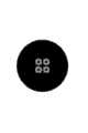
图2 是本发明实施例1的光子晶体光纤模场分布图。Fig. 2 is a distribution diagram of the mode field of the photonic crystal fiber in
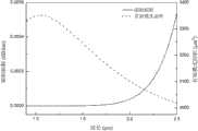
图3 是本发明实施例1光子晶体光纤的有效模式面积和限制损耗随波长变化关系图。Fig. 3 is a graph showing the relationship between the effective mode area and the confinement loss of the photonic crystal fiber in
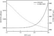
图4 是本发明实施例2光子晶体光纤的有效模式面积和限制损耗随波长变化关系图。Fig. 4 is a graph showing the relationship between the effective mode area and confinement loss of the photonic crystal fiber according to
图5 是本发明实施例3光子晶体光纤的有效模式面积和限制损耗随波长变化关系图。Fig. 5 is a graph showing the relationship between the effective mode area and confinement loss of the photonic crystal fiber according to Embodiment 3 of the present invention as a function of wavelength.
图6 是本发明实施例4光子晶体光纤的有效模式面积和限制损耗随波长变化关系图。Fig. 6 is a graph showing the relationship between the effective mode area and confinement loss of the photonic crystal fiber according to Embodiment 4 of the present invention as a function of wavelength.
具体实施方式Detailed ways
实施例1Example 1
在图1所示的本发明实施例1的光子晶体光纤横截面图中,该光纤主要是由纤芯和光纤包层组成的。其中,光纤包层1内有13′13-3′3′4=133个均匀的正方形阵列的空气孔2,空气孔直径d=4μm,两孔间距Λ=10μm。四组缺失3′3个空气孔的单元构成纤芯,四个纤芯对称地分布在四个象限的对角线上。每个纤芯包括有内芯3和掺杂的环形区域4,其中内芯为石英材质,其半径ra=6μm,而包在内芯外面的高掺杂环形区域为石英基掺杂了摩尔百分比为4.25%的二氧化锗,使其折射率为1.4504,略高于石英内芯的折射率1.45。上述高掺杂环形区域的厚度为其外环半径rb(为18μm)与内环半径ra的差,rb-ra=18-6=12μm。In the cross-sectional view of the photonic crystal fiber in
在图2所示的本发明实施例1的光纤在1.55 μm处的模场分布图中,从图中可以看出,各个纤芯输出的激光能量相同,并且在纤芯区域均匀分布,形成平顶模场。In the mode field distribution diagram of the optical fiber in Example 1 of the present invention shown in Figure 2 at 1.55 μm, it can be seen from the figure that the laser energy output by each fiber core is the same, and is uniformly distributed in the fiber core area, forming a flat Top mold field.
在图3所示的本发明实施例1光纤的有效模式面积和限制损耗随波长的变化关系图中,该光纤的有效模式面积在2900 μm2以上,属于大模式面积光纤,并且随着波长的增大其有效模式面积减小,在光通信的低损耗传输窗口λ=1.55 μm处,其有效模式面积为3107 μm2。在整个计算波长范围内,该光纤的限制损耗都极低。在传输窗口λ=1.55 μm处,它的限制损耗为9.71′10-6 dB/km。In Fig. 3, which shows the relationship between the effective mode area and confinement loss of the optical fiber of Example 1 of the present invention as a function of wavelength, the effective mode area of the optical fiber is above 2900μm2 , which belongs to a large mode area fiber, and increases with the wavelength Increasing its effective mode area decreases, and its effective mode area is 3107 μm2 at the low-loss transmission window of optical communication λ=1.55 μm. The confining loss of this fiber is extremely low over the entire calculated wavelength range. At the transmission window λ=1.55 μm, its limiting loss is 9.71′10-6 dB/km.
实施例2Example 2
本发明实施例2与实施例1基本相同,不同之处在于掺杂二氧化锗的摩尔百分比减小到4.11%(对应折射率1.4502),其有效模式面积和限制损耗随波长的变化关系如图4所示。从图中可以看出,该光纤与实施例1光纤相比,获得了较小的有效模式面积和更高的限制损耗。在λ=1.55 μm处,其有效模式面积为2934μm2,限制损耗为1.42′10-4 dB/km。Example 2 of the present invention is basically the same as Example 1, except that the molar percentage of doped germanium dioxide is reduced to 4.11% (corresponding to a refractive index of 1.4502), and the relationship between the effective mode area and confinement loss with wavelength is shown in the figure 4. It can be seen from the figure that, compared with the fiber in Example 1, the optical fiber has a smaller effective mode area and higher confinement loss. At λ=1.55 μm, its effective mode area is 2934μm2 , and the limiting loss is 1.42′10-4 dB/km.
实施例3Example 3
本发明实施例3与实施例1基本相同,不同之处在于掺杂二氧化锗的摩尔百分比增加到4.38%(对应折射率1.4506),其有效模式面积和限制损耗随波长的变化关系如图5所示。从图中可以看出,该光纤与第一实施例光纤相比获得了更大的有效模式面积和更低的限制损耗。在λ=1.55 μm处,其有效模式面积为3244μm2,限制损耗为1.32′10-6 dB/km。Example 3 of the present invention is basically the same as Example 1, except that the molar percentage of doped germanium dioxide is increased to 4.38% (corresponding to a refractive index of 1.4506), and the relationship between the effective mode area and confinement loss as a function of wavelength is shown in Figure 5 shown. It can be seen from the figure that the optical fiber has a larger effective mode area and lower confinement loss than the optical fiber of the first embodiment. At λ=1.55 μm, its effective mode area is 3244μm2 , and the limiting loss is 1.32′10-6 dB/km.
实施例4Example 4
本发明实施例4与实施例1基本相同,不同之处在于内纤芯半径ra增加到10μm,则掺杂圆环部分的厚度rb-ra=18-10=8μm,其有效模式面积和限制损耗随波长的变化关系如图6所示。从图中可以看出,该光纤与实施例1光纤相比,获得了更大的有效模式面积,但是限制损耗也有所增加。在λ=1.55 μm处,其有效模式面积为3395μm2,限制损耗为1.02′10-4 dB/km。Embodiment 4 of the present invention is basically the same as
Claims (2)
Translated fromChinesePriority Applications (1)
| Application Number | Priority Date | Filing Date | Title |
|---|---|---|---|
| CN201210268078.2ACN102819062B (en) | 2012-07-31 | 2012-07-31 | Air hole square array fiber core annular doping four-core photonic crystal fiber |
Applications Claiming Priority (1)
| Application Number | Priority Date | Filing Date | Title |
|---|---|---|---|
| CN201210268078.2ACN102819062B (en) | 2012-07-31 | 2012-07-31 | Air hole square array fiber core annular doping four-core photonic crystal fiber |
Publications (2)
| Publication Number | Publication Date |
|---|---|
| CN102819062Atrue CN102819062A (en) | 2012-12-12 |
| CN102819062B CN102819062B (en) | 2014-06-11 |
Family
ID=47303284
Family Applications (1)
| Application Number | Title | Priority Date | Filing Date |
|---|---|---|---|
| CN201210268078.2AExpired - Fee RelatedCN102819062B (en) | 2012-07-31 | 2012-07-31 | Air hole square array fiber core annular doping four-core photonic crystal fiber |
Country Status (1)
| Country | Link |
|---|---|
| CN (1) | CN102819062B (en) |
Cited By (4)
| Publication number | Priority date | Publication date | Assignee | Title |
|---|---|---|---|---|
| CN103760631A (en)* | 2013-12-13 | 2014-04-30 | 合肥工业大学 | Germanium-doped twin-core photonic crystal fiber |
| CN112859234A (en)* | 2021-03-03 | 2021-05-28 | 唐山学院 | Microstructure optical fiber broadband polarization filter with tunable filtering direction |
| CN113031147A (en)* | 2021-03-15 | 2021-06-25 | 南京邮电大学 | Homogenization optical fiber with multilayer square structure |
| CN113662658A (en)* | 2021-08-26 | 2021-11-19 | 桂林电子科技大学 | Medical optical fiber integrating annular core and image transmission bundle and preparation method thereof |
Citations (5)
| Publication number | Priority date | Publication date | Assignee | Title |
|---|---|---|---|---|
| US6301420B1 (en)* | 1998-05-01 | 2001-10-09 | The Secretary Of State For Defence In Her Britannic Majesty's Government Of The United Kingdom Of Great Britain And Northern Ireland | Multicore optical fibre |
| US20030059185A1 (en)* | 1999-12-10 | 2003-03-27 | Russell Philip St. John | Photonic crystal fibers |
| CN101339820A (en)* | 2008-08-19 | 2009-01-07 | 清华大学 | A kind of photoelectric simultaneous transmission fiber and its manufacturing method |
| CN101622560A (en)* | 2007-03-05 | 2010-01-06 | 株式会社藤仓 | Photonic band gap fiber |
| CN102257415A (en)* | 2008-12-24 | 2011-11-23 | 古河电气工业株式会社 | Multi-core optical fiber |
- 2012
- 2012-07-31CNCN201210268078.2Apatent/CN102819062B/ennot_activeExpired - Fee Related
Patent Citations (5)
| Publication number | Priority date | Publication date | Assignee | Title |
|---|---|---|---|---|
| US6301420B1 (en)* | 1998-05-01 | 2001-10-09 | The Secretary Of State For Defence In Her Britannic Majesty's Government Of The United Kingdom Of Great Britain And Northern Ireland | Multicore optical fibre |
| US20030059185A1 (en)* | 1999-12-10 | 2003-03-27 | Russell Philip St. John | Photonic crystal fibers |
| CN101622560A (en)* | 2007-03-05 | 2010-01-06 | 株式会社藤仓 | Photonic band gap fiber |
| CN101339820A (en)* | 2008-08-19 | 2009-01-07 | 清华大学 | A kind of photoelectric simultaneous transmission fiber and its manufacturing method |
| CN102257415A (en)* | 2008-12-24 | 2011-11-23 | 古河电气工业株式会社 | Multi-core optical fiber |
Cited By (6)
| Publication number | Priority date | Publication date | Assignee | Title |
|---|---|---|---|---|
| CN103760631A (en)* | 2013-12-13 | 2014-04-30 | 合肥工业大学 | Germanium-doped twin-core photonic crystal fiber |
| CN103760631B (en)* | 2013-12-13 | 2016-08-17 | 合肥工业大学 | A kind of Ge-doped double-core photonic crystal fiber |
| CN112859234A (en)* | 2021-03-03 | 2021-05-28 | 唐山学院 | Microstructure optical fiber broadband polarization filter with tunable filtering direction |
| CN112859234B (en)* | 2021-03-03 | 2022-04-29 | 唐山学院 | Microstructure optical fiber broadband polarization filter with tunable filtering direction |
| CN113031147A (en)* | 2021-03-15 | 2021-06-25 | 南京邮电大学 | Homogenization optical fiber with multilayer square structure |
| CN113662658A (en)* | 2021-08-26 | 2021-11-19 | 桂林电子科技大学 | Medical optical fiber integrating annular core and image transmission bundle and preparation method thereof |
Also Published As
| Publication number | Publication date |
|---|---|
| CN102819062B (en) | 2014-06-11 |
Similar Documents
| Publication | Publication Date | Title |
|---|---|---|
| CN102298173B (en) | Lateral pumped fiber structure and manufacturing method thereof | |
| CN100495093C (en) | Strongly coupled multi-core optical fiber | |
| CN101464538A (en) | Photonic crystal fiber with ultra-high double refraction and ultra-low limitation loss | |
| CN113497404B (en) | Rare earth-doped hollow anti-resonance optical fiber and preparation method thereof | |
| CN104503020A (en) | Longitudinal spiral mode transfer optical fiber | |
| CN103645536B (en) | A kind of all solid state large mould field photon band-gap optical fiber | |
| CN103472527A (en) | High-birefringence low-confinement-loss photonic crystal fiber | |
| CN104297837A (en) | Single-core photonic crystal fiber polarization splitter | |
| US20110026890A1 (en) | Holey fibers | |
| CN102401934A (en) | Dispersion Flattened Photonic Crystal Fiber | |
| CN102819062A (en) | Air hole square array fiber core annular doping four-core photonic crystal fiber | |
| CN202995205U (en) | Multicore photonic crystal fiber based supercontinuum source | |
| CN107272110B (en) | A kind of ZBLAN fluoride photonic crystal fiber of super large positive dispersion | |
| CN103439763B (en) | A kind of total solid optical fiber with large-mode field area and manufacture method thereof | |
| CN102368103B (en) | Microstructure optical fiber with large mode area | |
| CN101620295A (en) | Large mode area multi-core fiber | |
| CN110989072A (en) | A Large Mode Field Single Mode Fiber with Multi-Clad Helical Structure | |
| CN101122654A (en) | Large Mode Field Multicore Fiber | |
| CN104020521A (en) | Square structured all-solid-state band gap fiber | |
| CN109143457B (en) | Large-mode-field all-solid-state optical fiber and preparation method thereof | |
| CN103091769B (en) | A kind of annular microstructured optical fibers | |
| CN216958843U (en) | Large mode field single mode fiber | |
| CN107621669B (en) | Low-nonlinearity-coefficient few-mode optical fiber with depressed refractive index cladding | |
| CN106908894B (en) | A dispersion-flattened all-solid microstructured fiber | |
| WO2017101051A1 (en) | Optical fibre coupler for non-circular symmetrical mode |
Legal Events
| Date | Code | Title | Description |
|---|---|---|---|
| C06 | Publication | ||
| PB01 | Publication | ||
| C10 | Entry into substantive examination | ||
| SE01 | Entry into force of request for substantive examination | ||
| C14 | Grant of patent or utility model | ||
| GR01 | Patent grant | ||
| CF01 | Termination of patent right due to non-payment of annual fee | Granted publication date:20140611 Termination date:20170731 | |
| CF01 | Termination of patent right due to non-payment of annual fee |