CN102809999A - a cabinet - Google Patents
a cabinetDownload PDFInfo
- Publication number
- CN102809999A CN102809999ACN2011101485237ACN201110148523ACN102809999ACN 102809999 ACN102809999 ACN 102809999ACN 2011101485237 ACN2011101485237 ACN 2011101485237ACN 201110148523 ACN201110148523 ACN 201110148523ACN 102809999 ACN102809999 ACN 102809999A
- Authority
- CN
- China
- Prior art keywords
- cabinet
- display screen
- cabinet door
- visual device
- motor
- Prior art date
- Legal status (The legal status is an assumption and is not a legal conclusion. Google has not performed a legal analysis and makes no representation as to the accuracy of the status listed.)
- Pending
Links
Images


Classifications
- G—PHYSICS
- G06—COMPUTING OR CALCULATING; COUNTING
- G06F—ELECTRIC DIGITAL DATA PROCESSING
- G06F1/00—Details not covered by groups G06F3/00 - G06F13/00 and G06F21/00
- G06F1/16—Constructional details or arrangements
- G06F1/1601—Constructional details related to the housing of computer displays, e.g. of CRT monitors, of flat displays
- G—PHYSICS
- G06—COMPUTING OR CALCULATING; COUNTING
- G06F—ELECTRIC DIGITAL DATA PROCESSING
- G06F1/00—Details not covered by groups G06F3/00 - G06F13/00 and G06F21/00
- G06F1/16—Constructional details or arrangements
- G06F1/18—Packaging or power distribution
- G06F1/181—Enclosures
- G—PHYSICS
- G06—COMPUTING OR CALCULATING; COUNTING
- G06F—ELECTRIC DIGITAL DATA PROCESSING
- G06F3/00—Input arrangements for transferring data to be processed into a form capable of being handled by the computer; Output arrangements for transferring data from processing unit to output unit, e.g. interface arrangements
- G06F3/01—Input arrangements or combined input and output arrangements for interaction between user and computer
- G06F3/03—Arrangements for converting the position or the displacement of a member into a coded form
- G06F3/041—Digitisers, e.g. for touch screens or touch pads, characterised by the transducing means
- H—ELECTRICITY
- H05—ELECTRIC TECHNIQUES NOT OTHERWISE PROVIDED FOR
- H05K—PRINTED CIRCUITS; CASINGS OR CONSTRUCTIONAL DETAILS OF ELECTRIC APPARATUS; MANUFACTURE OF ASSEMBLAGES OF ELECTRICAL COMPONENTS
- H05K7/00—Constructional details common to different types of electric apparatus
- H05K7/14—Mounting supporting structure in casing or on frame or rack
- H05K7/1485—Servers; Data center rooms, e.g. 19-inch computer racks
- H05K7/1488—Cabinets therefor, e.g. chassis or racks or mechanical interfaces between blades and support structures
- H05K7/1494—Cabinets therefor, e.g. chassis or racks or mechanical interfaces between blades and support structures having hardware for monitoring blades, e.g. keyboards, displays
- G—PHYSICS
- G06—COMPUTING OR CALCULATING; COUNTING
- G06F—ELECTRIC DIGITAL DATA PROCESSING
- G06F2200/00—Indexing scheme relating to G06F1/04 - G06F1/32
- G06F2200/16—Indexing scheme relating to G06F1/16 - G06F1/18
- G06F2200/161—Indexing scheme relating to constructional details of the monitor
- G06F2200/1612—Flat panel monitor
- G—PHYSICS
- G06—COMPUTING OR CALCULATING; COUNTING
- G06F—ELECTRIC DIGITAL DATA PROCESSING
- G06F2200/00—Indexing scheme relating to G06F1/04 - G06F1/32
- G06F2200/16—Indexing scheme relating to G06F1/16 - G06F1/18
- G06F2200/161—Indexing scheme relating to constructional details of the monitor
- G06F2200/1614—Image rotation following screen orientation, e.g. switching from landscape to portrait mode
Landscapes
- Engineering & Computer Science (AREA)
- General Engineering & Computer Science (AREA)
- Theoretical Computer Science (AREA)
- Computer Hardware Design (AREA)
- Human Computer Interaction (AREA)
- Physics & Mathematics (AREA)
- General Physics & Mathematics (AREA)
- Power Engineering (AREA)
- Microelectronics & Electronic Packaging (AREA)
- Devices For Indicating Variable Information By Combining Individual Elements (AREA)
- Casings For Electric Apparatus (AREA)
Abstract
Translated fromChinese
Description
Translated fromChinese技术领域technical field
本发明为一种机柜,尤其是一种安装有旋转可视装置的机柜。The invention relates to a cabinet, in particular to a cabinet equipped with a rotating visual device.
背景技术Background technique
目前现有的机柜内部都会放置一套显示器以及键盘鼠标通过多电脑切换器(KVM)去维护机柜中的服务器以及其它设备,但这样布局设置很浪费机柜内部空间,集成型KVM能节省空间但价格过高,另外,当对机柜中的设备巡视时,必须打开柜门才可打开显示器进行相关操作和浏览显示界面的内容,当机房机柜很多时,浪费时间,影响操作效果。At present, a set of monitors, keyboards and mice are placed inside the existing cabinets to maintain servers and other equipment in the cabinets through a KVM switch. However, such layout settings waste the internal space of the cabinets. The integrated KVM can save space but is expensive. It is too high. In addition, when inspecting the equipment in the cabinet, the cabinet door must be opened to open the display to perform related operations and browse the content of the display interface. When there are many cabinets in the computer room, time is wasted and the operation effect is affected.
发明内容Contents of the invention
有鉴于此,有必要提供一种安装旋转可视装置的、且成本较低的旋转可视装置机柜。In view of this, it is necessary to provide a low-cost rotating display device cabinet for installing the rotating display device.
一机柜,包括一柜体、一柜门及一旋转可视装置,柜门可旋转地安装在柜体上,该旋转可视装置可旋转地安装在柜门上,并能以自动或手动的方式调节其相对于柜门的角度。A cabinet includes a cabinet body, a cabinet door and a rotating visual device, the cabinet door is rotatably installed on the cabinet body, the rotating visual device is rotatably mounted on the cabinet door, and can be automatically or manually way to adjust its angle relative to the cabinet door.
相较现有技术,该机柜将旋转可视装置集成于其机柜的柜门上,可有效节省柜内空间,当对柜内服务器进行各项操作时,可将该旋转可视装置的显示屏转向内部以利于显示与操作,并且显示屏可根据实际情况任意自由旋转,根据需要来手动或自动控制开关来调节显示屏旋转的角度,使其可转动从0度至360度,当操作完成时,可将显示屏转向外部,此时,可直接在机柜外通过显示器监视服务器运行情况。Compared with the prior art, the cabinet integrates the rotating visual device on the cabinet door, which can effectively save the space in the cabinet. When performing various operations on the server in the cabinet, the display screen of the rotating visual device can Turn to the inside to facilitate display and operation, and the display screen can be freely rotated according to the actual situation. According to the need, manually or automatically control the switch to adjust the rotation angle of the display screen, so that it can rotate from 0 degrees to 360 degrees. When the operation is completed , the display screen can be turned to the outside. At this time, the running status of the server can be monitored directly outside the cabinet through the display screen.
附图说明Description of drawings
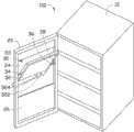
图1是本发明机柜的柜门闭合时旋转可视装置状态示意图;Fig. 1 is a schematic diagram of the state of the rotating visual device when the cabinet door of the cabinet of the present invention is closed;
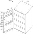
图2是本发明机柜的柜门开启时旋转可视装置旋转状态示意图;Fig. 2 is a schematic diagram of the rotating state of the rotating visual device when the cabinet door of the cabinet of the present invention is opened;
图3是本发明机柜的柜门开启时旋转可视装置另一状态示意图;Fig. 3 is a schematic diagram of another state of the rotating visual device when the cabinet door of the cabinet of the present invention is opened;
图4是本发明机柜上的旋转可视装置中的电路控制示意图。Fig. 4 is a schematic diagram of circuit control in the rotating visual device on the cabinet of the present invention.
主要元件符号说明Description of main component symbols
如下具体实施方式将结合上述附图进一步说明本发明。The following specific embodiments will further illustrate the present invention in conjunction with the above-mentioned drawings.
具体实施方式Detailed ways
本发明较佳实施例为图1及图2所示的一机柜100,机柜100包括一柜体10、一柜门20以及安装在柜门上的一旋转可视装置30。A preferred embodiment of the present invention is a
请参阅图1,该柜体10大致为一立方体,其内部架设有各种类型的电子设备或终端(未图示)。Please refer to FIG. 1 , the
该柜门20与该柜体10旋转连接以便开启该柜体10关闭柜体10。该柜门20包括在其上开设一中空部24,由此将柜门20切分成一上部22及一下部26,该上部22与下部26分别为一面板,材质可以透明玻璃、塑料或金属材质,该中空部24用以容置且安装该旋转可视装置30。The
该旋转可视装置30包括一显示屏32、一连接于显示屏32且可使显示屏32在中空部24内旋转的旋转机构(图未标)。旋转机构包括从动轴34、驱动轴36及电机38。图1所示的显示屏32的边框的上部设有电源开关322及按钮324。The rotating
组装并使用该设有旋转可视装置的机柜100时,首先,将该旋转可视装置30中的显示屏32安装在机柜10的柜门20的中空部24,该旋转可视装置30中的从动轴34的一端可转动地连接在显示屏32端部,该从动轴34的另一端连接在柜门20,该电机38与驱动轴36的一端连接,该驱动轴36的另一端连接该显示屏32远离从动轴36另一端。启动电机38可带动驱动轴36转动。在优选的本实例中,该驱动轴36和电机38二者的连接方式可以通过如下达成:在该驱动轴36在靠近柜体10的一端设有齿轮(未图示),通过安装在柜门20侧框内的电机38中的齿轮相配合,驱使带动驱动轴36转动,从而使固定在驱动轴36上的显示屏32一起转动,达到所设定的旋转角度。When assembling and using the
当然,本发明也可以通过手动的方式来解决如何通过驱动轴36带动的显示屏32进行旋转的问题,然而,如何以自动控制的方式进行自动调节可包括但不限于如下几种:Of course, the present invention can also manually solve the problem of how to rotate the
请参见图2及图3,在本优选的实施例中,该显示屏32内部集成的控制电路,该控制电路包括一中央处理器(CPU)、一存储单元。通过显示屏32上的按钮324,输入指令信号给嵌入显示屏内的中央处理器(未图示),输出指令信号给安装在柜门20边框内的电机38,从而控制电机38的启动与制动,来带动驱动轴36转动至一定角度。例如,依次按动按钮324驱动轴36以及其带动的显示屏32可分别相对开始位置转至30度、60度、120度、180度及360度。当然,其对应按钮324的按动,而具体转动的具体角度可进行任意设定。Please refer to FIG. 2 and FIG. 3 , in this preferred embodiment, the control circuit integrated in the
可以理解,该显示屏可为触控屏,而如何通过驱动轴36带动的显示屏32进行旋转的控制方式,可以通过触摸触控屏输出指令给电机38并控制电机38的的启动与制动来达成。It can be understood that the display screen can be a touch screen, and how to control the rotation of the
另外可以理解的方式为:如图4所示,显示屏32,如上所述其内部集成有一控制电路,该控制电路包括一中央处理器(CPU)、一存储单元。首先通过开启电源开关322,之后,通过按压按钮324给中央处理器(CPU)输入命令指令,中央处理器处理命令指令,并生成信号输入并以控制电机38的启动及制动,由此电机38带动驱动轴36转动指令的角度,从而带动固定在驱动轴36上的显示屏32转动,达到所需要的可视角度。Another way that can be understood is: as shown in FIG. 4 , the
另外,在本实施例中,该控制电路还可设置一存储单元,该存储单元存储每次中央处理器处理的信号,待下一次打开电源322后,如果中央处理器未收到新接受的外部指令时,系统会自动从存储器中提取最近一次系统运行的信息,自动运行,将显示屏32调整到前次的使用状态。In addition, in this embodiment, the control circuit can also be provided with a storage unit, which stores the signal processed by the central processing unit each time. After the
另外,可以理解,为方便操作者查看显示屏32的显示画面,显示屏32可于内部集成重力感应系统。由此,可使当显示屏32在由朝向柜门20外侧的位置转至朝向柜门20内侧的位置时,显示器画面可自动做镜像翻转,从而以利操作者查看。In addition, it can be understood that the
本发明在机柜10内服务器进行各项操作时,可根据需要来手动或自动控制来调节显示屏32自由旋转的角度,从而方便在机柜10内侧对显示器32操控和监视服务器运行情况。When the server in the
Claims (9)
Translated fromChinesePriority Applications (4)
| Application Number | Priority Date | Filing Date | Title |
|---|---|---|---|
| CN2011101485237ACN102809999A (en) | 2011-06-03 | 2011-06-03 | a cabinet |
| TW100119745ATW201251584A (en) | 2011-06-03 | 2011-06-07 | Cabinet |
| US13/331,711US20120307456A1 (en) | 2011-06-03 | 2011-12-20 | Network cabinet |
| JP2012116381AJP2012252692A (en) | 2011-06-03 | 2012-05-22 | cabinet |
Applications Claiming Priority (1)
| Application Number | Priority Date | Filing Date | Title |
|---|---|---|---|
| CN2011101485237ACN102809999A (en) | 2011-06-03 | 2011-06-03 | a cabinet |
Publications (1)
| Publication Number | Publication Date |
|---|---|
| CN102809999Atrue CN102809999A (en) | 2012-12-05 |
Family
ID=47233713
Family Applications (1)
| Application Number | Title | Priority Date | Filing Date |
|---|---|---|---|
| CN2011101485237APendingCN102809999A (en) | 2011-06-03 | 2011-06-03 | a cabinet |
Country Status (4)
| Country | Link |
|---|---|
| US (1) | US20120307456A1 (en) |
| JP (1) | JP2012252692A (en) |
| CN (1) | CN102809999A (en) |
| TW (1) | TW201251584A (en) |
Cited By (6)
| Publication number | Priority date | Publication date | Assignee | Title |
|---|---|---|---|---|
| CN103640032A (en)* | 2013-11-28 | 2014-03-19 | 北京智能佳科技有限公司 | Tray displaying device and service robot |
| CN104734130A (en)* | 2013-12-19 | 2015-06-24 | 孙巍巍 | Novel lightning protection cabinet |
| CN107817874A (en)* | 2017-10-20 | 2018-03-20 | 紫光华山信息技术有限公司 | Diagnostic module, management module and electronic equipment |
| CN107850266A (en)* | 2015-07-31 | 2018-03-27 | 乔治洛德方法研究和开发液化空气有限公司 | Pivotable touch-screen for gas distribution apparatus |
| CN108879398A (en)* | 2018-07-02 | 2018-11-23 | 安徽泾县宏图信息科技有限公司 | A kind of power information server control cabinet |
| CN111949090A (en)* | 2020-09-24 | 2020-11-17 | 陈弋函 | Special control device capable of automatically adjusting temperature for cabinet type computer |
Families Citing this family (13)
| Publication number | Priority date | Publication date | Assignee | Title |
|---|---|---|---|---|
| FR3004015B1 (en)* | 2013-03-28 | 2015-03-20 | Vit | ENCLOSURE OF INDUSTRIAL EQUIPMENT |
| CN103279064A (en)* | 2013-05-10 | 2013-09-04 | 昆山市三羊纺织机械有限公司 | Touch electric control gear |
| USD740282S1 (en)* | 2013-10-22 | 2015-10-06 | Western Digital Technologies, Inc. | Storage device |
| USD760222S1 (en) | 2014-10-29 | 2016-06-28 | Western Digital Technologies, Inc. | Storage device |
| CN104751581A (en)* | 2015-03-20 | 2015-07-01 | 国家电网公司 | Intelligent electric cabinet with safety protection system |
| US10595434B2 (en)* | 2017-09-26 | 2020-03-17 | Quanta Computer Inc. | Asset tag holder mechanism to improve accessibility |
| IT201800003516A1 (en)* | 2018-03-13 | 2019-09-13 | Bticino Spa | CABINET FOR ELECTRICAL EQUIPMENT |
| GB2574025A (en)* | 2018-05-23 | 2019-11-27 | Eaton Intelligent Power Ltd | Display device |
| KR20210050128A (en)* | 2019-10-28 | 2021-05-07 | 삼성전자주식회사 | Refrigerator |
| CN111148417A (en)* | 2020-03-25 | 2020-05-12 | 瑞德(新乡)路业有限公司 | A mobile cabinet for online monitoring device for cooking oil fume |
| CN112543565B (en)* | 2020-12-04 | 2022-03-11 | 上海知到知识数字科技有限公司 | Teaching content feedback system for education |
| LU504170B1 (en)* | 2023-05-09 | 2024-11-11 | Phoenix Contact Gmbh & Co | One-sided accessible electrical module and cabinet |
| CN118400496B (en)* | 2024-05-28 | 2025-05-09 | 余清华 | Video remote transmission system for high voltage distribution cabinet |
Citations (5)
| Publication number | Priority date | Publication date | Assignee | Title |
|---|---|---|---|---|
| JP2003029873A (en)* | 2001-07-17 | 2003-01-31 | Hitachi Ltd | Rack mount cabinet |
| US6529123B1 (en)* | 1999-11-02 | 2003-03-04 | Rosen Products Llc | Automatically deployable and stowable display monitor |
| CN2886755Y (en)* | 2006-02-18 | 2007-04-04 | 鸿富锦精密工业(深圳)有限公司 | Display device |
| CN101163613A (en)* | 2005-05-26 | 2008-04-16 | 三菱电机株式会社 | Display device |
| US7869201B2 (en)* | 2007-01-04 | 2011-01-11 | Whirlpool Corporation | Host and adapter for selectively positioning a consumer electronic display in visible and concealed orientations |
Family Cites Families (19)
| Publication number | Priority date | Publication date | Assignee | Title |
|---|---|---|---|---|
| US6510049B2 (en)* | 2000-01-06 | 2003-01-21 | Rosen Products Llc | Adjustable display monitor unit |
| JP2003150067A (en)* | 2001-11-09 | 2003-05-21 | Canon Inc | Flat display device |
| US20050063145A1 (en)* | 2003-09-18 | 2005-03-24 | Homer Steven S. | Computer system with rotatable display |
| TWM246671U (en)* | 2003-11-07 | 2004-10-11 | Tatung Co | Positioning structure of rotation-type display |
| TWM247895U (en)* | 2003-12-10 | 2004-10-21 | Tatung Co | Improved frame structure in rotational display |
| KR100619336B1 (en)* | 2004-12-23 | 2006-09-08 | 엘지전자 주식회사 | Retractable monitor driving device and control method in vehicle AV system |
| JP4559891B2 (en)* | 2005-03-28 | 2010-10-13 | 東亜ディーケーケー株式会社 | Cabinet equipment |
| WO2006126623A1 (en)* | 2005-05-27 | 2006-11-30 | Matsushita Electric Industrial Co., Ltd. | Power transmission device, and display device and display panel pedestal that have the power transmission device |
| JP4765696B2 (en)* | 2006-03-16 | 2011-09-07 | ソニー株式会社 | Car equipment |
| KR100882619B1 (en)* | 2006-06-21 | 2009-02-06 | 엘지전자 주식회사 | Display Assembly for Refrigerator |
| JP2008288963A (en)* | 2007-05-18 | 2008-11-27 | Funai Electric Co Ltd | Display system |
| JP4321627B2 (en)* | 2007-05-30 | 2009-08-26 | ソニー株式会社 | Stand for image display device |
| US8313072B2 (en)* | 2007-08-27 | 2012-11-20 | Hewlett-Packard Development Company, L. P. | Monitor as a door |
| US8454436B2 (en)* | 2008-06-26 | 2013-06-04 | Wms Gaming Inc. | Gaming machine with movable display screen |
| US7742287B2 (en)* | 2008-07-16 | 2010-06-22 | International Business Machines Corporation | Apparatus for display movement of a laptop computer |
| CN101739082A (en)* | 2008-11-19 | 2010-06-16 | 鸿富锦精密工业(深圳)有限公司 | Electronic devices with display screens |
| TWI413480B (en)* | 2009-06-30 | 2013-10-21 | Ibm | Mount assembly and rack mount system having the same |
| TW201123032A (en)* | 2009-12-30 | 2011-07-01 | Hon Hai Prec Ind Co Ltd | Monitor adjusting system and the method use the same |
| US8619172B2 (en)* | 2010-03-31 | 2013-12-31 | Hewlett-Packard Development Company, L.P. | Rotatable camera assembly |
- 2011
- 2011-06-03CNCN2011101485237Apatent/CN102809999A/enactivePending
- 2011-06-07TWTW100119745Apatent/TW201251584A/enunknown
- 2011-12-20USUS13/331,711patent/US20120307456A1/ennot_activeAbandoned
- 2012
- 2012-05-22JPJP2012116381Apatent/JP2012252692A/enactivePending
Patent Citations (5)
| Publication number | Priority date | Publication date | Assignee | Title |
|---|---|---|---|---|
| US6529123B1 (en)* | 1999-11-02 | 2003-03-04 | Rosen Products Llc | Automatically deployable and stowable display monitor |
| JP2003029873A (en)* | 2001-07-17 | 2003-01-31 | Hitachi Ltd | Rack mount cabinet |
| CN101163613A (en)* | 2005-05-26 | 2008-04-16 | 三菱电机株式会社 | Display device |
| CN2886755Y (en)* | 2006-02-18 | 2007-04-04 | 鸿富锦精密工业(深圳)有限公司 | Display device |
| US7869201B2 (en)* | 2007-01-04 | 2011-01-11 | Whirlpool Corporation | Host and adapter for selectively positioning a consumer electronic display in visible and concealed orientations |
Cited By (10)
| Publication number | Priority date | Publication date | Assignee | Title |
|---|---|---|---|---|
| CN103640032A (en)* | 2013-11-28 | 2014-03-19 | 北京智能佳科技有限公司 | Tray displaying device and service robot |
| CN103640032B (en)* | 2013-11-28 | 2015-08-26 | 北京智能佳科技有限公司 | Pallet display unit and service robot |
| CN104734130A (en)* | 2013-12-19 | 2015-06-24 | 孙巍巍 | Novel lightning protection cabinet |
| CN107850266A (en)* | 2015-07-31 | 2018-03-27 | 乔治洛德方法研究和开发液化空气有限公司 | Pivotable touch-screen for gas distribution apparatus |
| US20180320825A1 (en)* | 2015-07-31 | 2018-11-08 | L' Air Liquide, Société Anonyme pour l'Etude et l'Exploitation des Procédés Georges Claude | Pivotable touchscreen for a gas-distribution facility |
| US10823336B2 (en) | 2015-07-31 | 2020-11-03 | L'Air Liquide, Société Anonyme pour l'Etude et l'Exploitation des Procédés Georges Claude | Pivotable touchscreen for a gas-distribution facility |
| CN107817874A (en)* | 2017-10-20 | 2018-03-20 | 紫光华山信息技术有限公司 | Diagnostic module, management module and electronic equipment |
| CN107817874B (en)* | 2017-10-20 | 2020-01-03 | 新华三信息技术有限公司 | Diagnosis module, management module and electronic equipment |
| CN108879398A (en)* | 2018-07-02 | 2018-11-23 | 安徽泾县宏图信息科技有限公司 | A kind of power information server control cabinet |
| CN111949090A (en)* | 2020-09-24 | 2020-11-17 | 陈弋函 | Special control device capable of automatically adjusting temperature for cabinet type computer |
Also Published As
| Publication number | Publication date |
|---|---|
| US20120307456A1 (en) | 2012-12-06 |
| TW201251584A (en) | 2012-12-16 |
| JP2012252692A (en) | 2012-12-20 |
Similar Documents
| Publication | Publication Date | Title |
|---|---|---|
| CN102809999A (en) | a cabinet | |
| CN108227824B (en) | Control knob for controlling operation of a machine | |
| US20090231307A1 (en) | Display apparatus for displaying still image with low power consumption and method of displaying still image using the display apparatus | |
| US20130163201A1 (en) | Electronic device | |
| US7251142B2 (en) | Timer switch | |
| CN103135850A (en) | Handheld electronic device and touch method thereof | |
| US11392178B2 (en) | Locking hinges | |
| US20070205909A1 (en) | Remote controller and its content downloading and executing method | |
| WO2021129383A1 (en) | Refrigeration device and control method therefor, and computer-readable storage medium | |
| CN112222794A (en) | Split screen device | |
| CN104598153A (en) | Method for controlling server and server | |
| WO2021097870A1 (en) | Electronic product development experimental platform | |
| CN104932634A (en) | Case | |
| CN103257737B (en) | Integrated touch screen control module | |
| CN112524079B (en) | Fan, fan control method and device and storage medium | |
| CN205375316U (en) | Intelligent computer of shielding more | |
| CN103574237A (en) | LCD (Liquid Crystal Display) screen lifter with pitching mechanical connecting rod transmission device | |
| CN206541191U (en) | A kind of programmable controller | |
| CN103092376A (en) | Method and device for generating control commands and electronic equipment | |
| CN207867450U (en) | A kind of intelligent apparatus for computer remote booting | |
| CN102411407B (en) | Automatic opening and closing notebook computer | |
| CN111070162A (en) | A locking screw machine with torque error proofing and screw leakage proofing functions | |
| CN104571665A (en) | Touch-control operation display and implementation method thereof | |
| CN203452914U (en) | Turbine worm minute adjustment device for fuel injection pump | |
| CN220853871U (en) | A product data collection and monitoring device for an aging room |
Legal Events
| Date | Code | Title | Description |
|---|---|---|---|
| C06 | Publication | ||
| PB01 | Publication | ||
| C10 | Entry into substantive examination | ||
| SE01 | Entry into force of request for substantive examination | ||
| C02 | Deemed withdrawal of patent application after publication (patent law 2001) | ||
| WD01 | Invention patent application deemed withdrawn after publication | Application publication date:20121205 |