CN102808886A - Shock absorber and suspension apparatus - Google Patents
Shock absorber and suspension apparatusDownload PDFInfo
- Publication number
- CN102808886A CN102808886ACN2012101760718ACN201210176071ACN102808886ACN 102808886 ACN102808886 ACN 102808886ACN 2012101760718 ACN2012101760718 ACN 2012101760718ACN 201210176071 ACN201210176071 ACN 201210176071ACN 102808886 ACN102808886 ACN 102808886A
- Authority
- CN
- China
- Prior art keywords
- cylinder
- pilot
- damping force
- pump
- chamber
- Prior art date
- Legal status (The legal status is an assumption and is not a legal conclusion. Google has not performed a legal analysis and makes no representation as to the accuracy of the status listed.)
- Granted
Links
- 239000006096absorbing agentSubstances0.000titleclaimsabstractdescription37
- 230000035939shockEffects0.000titleclaimsabstractdescription37
- 239000000725suspensionSubstances0.000titleclaimsabstractdescription34
- 238000013016dampingMethods0.000claimsabstractdescription151
- 230000007246mechanismEffects0.000claimsabstractdescription69
- 239000012530fluidSubstances0.000claimsabstractdescription35
- 238000004891communicationMethods0.000claimsdescription71
- 238000011144upstream manufacturingMethods0.000claimsdescription22
- 230000002265preventionEffects0.000claimsdescription18
- 238000001514detection methodMethods0.000claimsdescription12
- 239000007788liquidSubstances0.000claimsdescription12
- 230000002457bidirectional effectEffects0.000claimsdescription4
- 238000007599dischargingMethods0.000claimsdescription3
- 230000009467reductionEffects0.000description22
- 230000008602contractionEffects0.000description21
- 239000007789gasSubstances0.000description14
- 230000006870functionEffects0.000description8
- 238000010586diagramMethods0.000description7
- 230000007423decreaseEffects0.000description6
- 230000000694effectsEffects0.000description6
- 230000001133accelerationEffects0.000description5
- IJGRMHOSHXDMSA-UHFFFAOYSA-NAtomic nitrogenChemical compoundN#NIJGRMHOSHXDMSA-UHFFFAOYSA-N0.000description4
- 230000002093peripheral effectEffects0.000description4
- 230000008929regenerationEffects0.000description4
- 238000011069regeneration methodMethods0.000description4
- 239000000654additiveSubstances0.000description2
- 238000006073displacement reactionMethods0.000description2
- 238000000034methodMethods0.000description2
- 238000012986modificationMethods0.000description2
- 230000004048modificationEffects0.000description2
- 229910052757nitrogenInorganic materials0.000description2
- 230000001172regenerating effectEffects0.000description2
- XLYOFNOQVPJJNP-UHFFFAOYSA-NwaterSubstancesOXLYOFNOQVPJJNP-UHFFFAOYSA-N0.000description2
- 230000009471actionEffects0.000description1
- 230000000996additive effectEffects0.000description1
- 230000002238attenuated effectEffects0.000description1
- 239000000470constituentSubstances0.000description1
- 238000011038discontinuous diafiltration by volume reductionMethods0.000description1
- 230000006872improvementEffects0.000description1
- 239000011295pitchSubstances0.000description1
- 238000010248power generationMethods0.000description1
- 230000004043responsivenessEffects0.000description1
- 238000005096rolling processMethods0.000description1
- 239000013585weight reducing agentSubstances0.000description1
Images


Classifications
- B—PERFORMING OPERATIONS; TRANSPORTING
- B60—VEHICLES IN GENERAL
- B60G—VEHICLE SUSPENSION ARRANGEMENTS
- B60G17/00—Resilient suspensions having means for adjusting the spring or vibration-damper characteristics, for regulating the distance between a supporting surface and a sprung part of vehicle or for locking suspension during use to meet varying vehicular or surface conditions, e.g. due to speed or load
- B60G17/06—Characteristics of dampers, e.g. mechanical dampers
- B60G17/08—Characteristics of fluid dampers
- B—PERFORMING OPERATIONS; TRANSPORTING
- B60—VEHICLES IN GENERAL
- B60G—VEHICLE SUSPENSION ARRANGEMENTS
- B60G2400/00—Indexing codes relating to detected, measured or calculated conditions or factors
- B60G2400/10—Acceleration; Deceleration
- B—PERFORMING OPERATIONS; TRANSPORTING
- B60—VEHICLES IN GENERAL
- B60G—VEHICLE SUSPENSION ARRANGEMENTS
- B60G2400/00—Indexing codes relating to detected, measured or calculated conditions or factors
- B60G2400/20—Speed
- B60G2400/204—Vehicle speed
- B—PERFORMING OPERATIONS; TRANSPORTING
- B60—VEHICLES IN GENERAL
- B60G—VEHICLE SUSPENSION ARRANGEMENTS
- B60G2400/00—Indexing codes relating to detected, measured or calculated conditions or factors
- B60G2400/25—Stroke; Height; Displacement
- B60G2400/252—Stroke; Height; Displacement vertical
- B—PERFORMING OPERATIONS; TRANSPORTING
- B60—VEHICLES IN GENERAL
- B60G—VEHICLE SUSPENSION ARRANGEMENTS
- B60G2400/00—Indexing codes relating to detected, measured or calculated conditions or factors
- B60G2400/50—Pressure
- B60G2400/51—Pressure in suspension unit
- B—PERFORMING OPERATIONS; TRANSPORTING
- B60—VEHICLES IN GENERAL
- B60G—VEHICLE SUSPENSION ARRANGEMENTS
- B60G2500/00—Indexing codes relating to the regulated action or device
- B60G2500/10—Damping action or damper
Landscapes
- Engineering & Computer Science (AREA)
- Mechanical Engineering (AREA)
- Vehicle Body Suspensions (AREA)
- Fluid-Damping Devices (AREA)
Abstract
Translated fromChinese
Description
Translated fromChinese技术领域technical field
本发明涉及例如用于对汽车等的振动进行缓冲的缓冲器以及悬架装置。The present invention relates to, for example, a shock absorber and a suspension device for damping vibration of an automobile or the like.
背景技术Background technique
通常,在两轮或四轮汽车等车辆中,在车轮侧与车体侧之间设有液压缓冲器,对行驶时产生的上下方向的振动等进行缓冲。作为这样的液压缓冲器,公知有可变地控制衰减力的被称为半自动悬架的结构(例如,参照日本特开2009-281584号公报)。Generally, in a vehicle such as a two-wheeled or four-wheeled vehicle, a hydraulic shock absorber is provided between the wheel side and the vehicle body side to cushion vibrations in the vertical direction generated during running. As such a hydraulic shock absorber, there is known a structure called a semi-automatic suspension that variably controls damping force (see, for example, JP-A-2009-281584).
现有技术中的作为缓冲器的半自动悬架通过对缸内油液的流动进行控制而可变地控制衰减力,能够节省能量并实现小型化。但是,与从外部向缸内供给、排出油液的自动悬架相比,衰减力的产生范围有限,仍然存在改善的余地。The semi-automatic suspension used as a shock absorber in the prior art controls the damping force variably by controlling the flow of oil in the cylinder, which can save energy and achieve miniaturization. However, compared with an automatic suspension that supplies and discharges oil from the outside to the cylinder, the damping force generation range is limited, and there is still room for improvement.
发明内容Contents of the invention
本发明的目的在于提供一种能够节省能量并可扩大衰减力的产生范围的缓冲器以及悬架装置。An object of the present invention is to provide a shock absorber and a suspension device capable of saving energy and expanding the generation range of damping force.
本发明的缓冲器包括:至少一个缸装置,其具有封入有动作流体的缸、以可滑动的方式插嵌在所述缸内且将所述缸内划分成两个室的活塞、与所述活塞连接且向所述缸的外部延伸出的活塞杆;至少一个衰减力产生机构,其与所述缸装置连接,相对于由所述活塞的移动而产生的所述动作流体的流动产生衰减力,并且可从外部对该衰减力进行调节。所述衰减力产生机构具有:衰减阀,其产生所述衰减力;先导室,其对所述衰减阀作用由所述动作流体产生的先导压;泵,其至少将所述动作流体向所述先导室供给或将所述动作流体从所述先导室排出。The shock absorber of the present invention includes: at least one cylinder device having a cylinder filled with a working fluid, a piston slidably inserted into the cylinder and dividing the cylinder into two chambers, and the a piston rod connected to the piston and extending to the outside of the cylinder; at least one damping force generating mechanism, which is connected to the cylinder device and generates a damping force with respect to the flow of the operating fluid generated by the movement of the piston , and the damping force can be adjusted externally. The damping force generating mechanism includes: a damping valve that generates the damping force; a pilot chamber that acts on the damping valve with a pilot pressure generated by the operating fluid; and a pump that at least sends the operating fluid to the A pilot chamber supplies or exhausts the actuating fluid from the pilot chamber.
另外,本发明提供具有所述缓冲器的悬架装置。根据本发明的一方面,悬架装置,包括:设于车辆的车体与车轮之间的所述缓冲器;对所述缓冲器的衰减力产生机构进行控制的控制器;可检测所述衰减阀上游侧的压力的上游压力检测机构,所述控制器基于所述上游压力检测机构的检测结果控制所述泵。In addition, the present invention provides a suspension device having the damper. According to an aspect of the present invention, a suspension device includes: the shock absorber provided between the body of the vehicle and the wheels; a controller for controlling a damping force generating mechanism of the shock absorber; capable of detecting the damping an upstream pressure detection mechanism for pressure on an upstream side of the valve, and the controller controls the pump based on a detection result of the upstream pressure detection mechanism.
附图说明Description of drawings
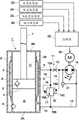
图1是表示本发明第一实施方式的液压缓冲器以及悬架装置的整体构成图;FIG. 1 is an overall configuration diagram showing a hydraulic shock absorber and a suspension device according to a first embodiment of the present invention;
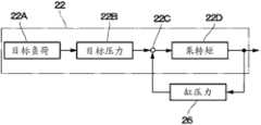
图2是表示图1中的控制器进行的泵转矩的运算处理电路的框图;Fig. 2 is a block diagram showing a calculation processing circuit of pump torque performed by the controller in Fig. 1;
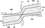
图3是表示图1的液压缓冲器的衰减力特性的特性线图;Fig. 3 is a characteristic diagram showing damping force characteristics of the hydraulic shock absorber of Fig. 1;
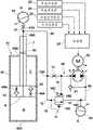
图4是表示第二实施方式的液压缓冲器以及悬架装置的整体构成图;4 is a diagram showing the overall configuration of a hydraulic shock absorber and a suspension device according to a second embodiment;
图5是表示第三实施方式的液压缓冲器以及悬架装置的整体构成图;5 is a diagram showing the overall configuration of a hydraulic shock absorber and a suspension device according to a third embodiment;
图6是表示第四实施方式的液压缓冲器以及悬架装置的整体构成图;6 is a diagram showing the overall configuration of a hydraulic shock absorber and a suspension device according to a fourth embodiment;
图7是表示第五实施方式的液压缓冲器以及悬架装置的整体构成图。FIG. 7 is an overall configuration diagram showing a hydraulic shock absorber and a suspension device according to a fifth embodiment.
具体实施方式Detailed ways
以下,以适用于车辆用的液压缓冲器的情况为例,基于附图对本发明实施方式的缓冲器以及悬架装置进行详细说明。Hereinafter, a shock absorber and a suspension device according to an embodiment of the present invention will be described in detail based on the drawings, taking the case of being applied to a hydraulic shock absorber for a vehicle as an example.
在此,图1~图3表示本发明的第一实施方式。附图中,1是构成液压缓冲器的主体部的液压缸、2是构成该液压缸1的外壳的有底筒状的外筒。外筒2的一端侧即下端侧成为底部2A而被闭塞。外筒2的另一端侧即上端侧被盖部2B闭塞。在该盖部2B的内周侧设有可滑动地支承后述的活塞杆7的杆导向件以及密封件(未图示)等。Here, FIGS. 1 to 3 show a first embodiment of the present invention. In the drawings, 1 is a hydraulic cylinder constituting the main body of the hydraulic shock absorber, and 2 is a bottomed cylindrical outer cylinder constituting the casing of the hydraulic cylinder 1 . One end side of the
3是同轴地设于外筒2内的作为缸的内筒,该内筒3在其内部封入有作为动作流体的油液。动作流体不限于油液、油,也可使用例如混合有添加剂的水等液体。在外筒2与内筒3之间形成有构成贮存器的环状贮存室A,在该贮存室A内与所述油液一同封入有气体。该气体既可以是大气压状态的空气,也可以使用被压缩后的氮气等气体。另外,在内筒3的长度方向(轴向)的中途位置,沿径向穿设有使后述的杆侧油室C总是与环状油室D连通的油孔3A。3 is an inner cylinder as a cylinder coaxially provided in the
4是以可滑动的方式插嵌在内筒3内的活塞,该活塞4将内筒3内划分成两个室,即作为下侧室的底侧油室B和作为上侧室的杆侧油室C。在活塞4设有单向阀5。该单向阀5允许油液从底侧油室B向杆侧油室C流通,阻止油液与之相反地从杆侧油室C向底侧油室B流通。另外,在活塞4也可以设有溢流阀,在杆侧油室C与底侧油室B的压差为所定以上时,溢流阀允许油液从杆侧油室C向底侧油室B流通,阻止油液与之相反地从底侧油室B向杆侧油室C流通。4 is a piston inserted into the
在内筒3的下端侧设有位于贮存室A与底侧油室B之间的底侧的单向阀6。该单向阀6允许油液从贮存室A向底侧油室B流通,阻止油液与之相反地从底侧油室B向贮存室A流通。另外,在内筒3的下端侧也可以设置溢流阀,在底侧油室B与贮存室A的压力差为所定以上时,溢流阀允许油液从底侧油室B向贮存室A流通,阻止油液与之相反地从贮存室A向底侧油室B流通。A
在后述的活塞杆7的缩小行程中使活塞4向下方滑动位移时,设于活塞4的单向阀5开阀,底侧的单向阀6闭阀。另一方面,在成为活塞杆7的伸长行程而使活塞4向上方滑动位移时,设于活塞4的单向阀5闭阀,底侧的单向阀6开阀。When the
7是在内筒3内轴向延伸的活塞杆,该活塞杆7将作为一端侧的下端侧插入内筒3内,固定设于活塞4。另外,活塞杆7的作为另一端侧的上端侧经由所述杆导向件以及盖部2B等以向外筒2以及内筒3的外部延伸的方式突出。
8是配设于外筒2与内筒3之间的中间筒,该中间筒8经由上、下密封件部材(都未图示)等安装在内筒3的外周侧。中间筒8在内部形成有以整周地包围的方式在内筒3的外周侧延伸的环状油室D,环状油室D成为与贮存室A独立的油室。环状油室D通过形成于内筒3的径向的油孔3A总是与杆侧油室C连通。另外,环状油室D只要能够起到作为通路的作用,也可以不是环状。
在中间筒8和外筒2设有在二者之间径向延伸的万向节9,该万向节9构成使环状油室D、杆侧油室C内的油液朝向后述的衰减力产生机构11的连通管路12流通的油路的一部分。在外筒2的下部侧形成有用于使油液在后述的衰减力产生机构11与贮存室A之间流入、流出的口10。Between the
11是第一实施方式中采用的衰减力产生机构,如图1所示,该衰减力产生机构11包括:在外筒2的外侧使所述万向节9和口10之间连通的连通管路12;设于该连通管路12中途的先导节流孔13;位于该先导节流孔13的下游侧且设于连通管路12中途的泵14;绕过先导节流孔13以及泵14而在分歧点15A、15B的位置与连通管路12连接的旁通管路15;设于该旁通管路15的中途且具有先导室16A、16B的溢流阀16;后述的电动机20以及过负荷防止阀21。11 is the damping force generating mechanism adopted in the first embodiment. As shown in FIG. 1 , the damping
其中,溢流阀16与先导节流孔13一同构成本发明的构成要件即衰减阀17。先导节流孔13的上游侧压力(即,杆侧油室C、万向节9内的压力)作为经过先导管路18后的先导压而向溢流阀16的先导室16A供给。通过该先导压,溢流阀16对抗压力设定弹簧16C等而被向开阀方向驱动。Among them, the
先导节流孔13的下游侧压力(即,泵14侧的压力)作为经过先导管路19后的先导压而向溢流阀16的先导室16B供给。通过该先导压,溢流阀16与压力设定弹簧16C一同被向闭阀方向驱动。即,先导室16B使经过先导管路19后的先导压作用于衰减阀17的溢流阀16。The pressure on the downstream side of the pilot orifice 13 (ie, the pressure on the
由此,溢流阀16通过压力设定弹簧16C总是被向闭阀方向施力,供给先导室16A的先导压在比先导室16B的先导压和压力设定弹簧16C的合计压力值低的期间,被保持为闭阀状态。但是,溢流阀16在供给先导室16A的先导压超过先导室16B的先导压和压力设定弹簧16C的合计压力值时开阀,允许油液从旁通管路15的分歧点15A向分歧点15B(即,贮存室A)流通。另外,也可以根据所希望的衰减力特性,在溢流阀16设置即使为闭阀状态也多少允许油液流通的固定节流孔,另外,还可以设置与压力设定弹簧16C相对的弹簧,在先导室16B的先导压极低的状态下,将溢流阀16稍微开阀。Thus, the
泵14是通过作为驱动源的电动机20向正、反方向(箭头标记E、F方向)旋转驱动的双向泵,能够在与贮存室A之间进行油液的给排,并且能够从先导室16B进行油液的给排。泵14在向图1中的箭头标记E方向旋转时,将先导节流孔13以及先导管路19内的油液向分歧点15B侧排出,使先导管路19以及先导室16B内的先导压降低。与之相反地,在泵14向图1中的箭头标记F方向旋转时,将分歧点15B(即,贮存室A)侧的油液向先导节流孔13以及先导管路19内供给,使先导管路19以及先导室16B内的先导压上升。The
21是泵14用的过负荷防止阀,该过负荷防止阀21以与泵14并列的方式在泵14的前后与连通管路12连接。过负荷防止阀21作为如下的安全泵而动作,即,例如在杆侧油室C(环状油室D)内的压力、先导节流孔13侧的压力超过预先设定的压力值(过剩压)时开阀,将此时的过剩压向分歧点15B(即,贮存室A)侧释放。
即,在被高压设定为比所述压力值(过剩压)高的溢流设定压的状态下使溢流阀16闭阀时,为了防止由所述过剩压对泵14施加过负荷,过负荷防止阀21开阀,除此之外时,过负荷防止阀21被保持为闭阀状态。例如,后述的图3所示的特性线29、30为由过负荷防止阀21的开阀决定的特性,若产生更高的衰减力,则为了防止在泵14上产生过负荷而导致故障的发生而使过负荷防止阀21开阀。另外,若设置在为所定压时使泵14停止的机构等,则也可以不设置过负荷防止阀21。That is, when the
22是由微机等构成的作为控制装置的控制器,如图1所示,该控制器22与车高传感器23、车速传感器24、上下方向的加速度传感器25以及压力传感器26等连接,输出侧与电动机20等连接。控制器22具有由ROM、RAM、非易失性存储器等构成的存储部(未图示),包含例如图2所示的泵转矩的运算处理电路等而构成。22 is the controller that is made up of microcomputer etc. as control device, as shown in Figure 1, this
控制器22的泵转矩的运算处理电路由图2所示的目标负荷运算部22A、目标压力运算部22B、偏差运算部22C以及泵转矩运算部22D等构成。目标负荷运算部22A通过来自车高传感器23、车速传感器24以及上下方向的加速度传感器25等的检测信号(更准确地说,包含车辆的转向角、制动液压、导航信息等与车体侧的动作相关的信号)计算为了使车体稳定而应在液压缸1的内筒3侧产生的目标负荷(目标衰减力)。The pump torque calculation processing circuit of the
目标压力运算部22B计算对应于该目标负荷的内筒3侧的目标压力。在车体与液压缸1之间,通常设有悬架弹簧(例如,空气悬架时为空气弹簧),故而通过在减去了悬架弹簧的负荷分担量的基础上,还考虑了活塞4、活塞杆7的外径、油孔3A的孔径、溢流阀16的通路面积等的运算式算出应在内筒3侧产生的目标压力。The target
在偏差运算部22C求出由压力传感器26检测到的实际缸压力(例如,在万向节9的位置检测到的环状油室D、杆侧油室C内的压力)与目标压力运算部22B的目标压力的偏差。泵转矩运算部22D作为泵转矩而算出以使此时的偏差处于预先决定的规定值范围内的方式应向电动机20输出的控制电流值。The difference between the actual cylinder pressure detected by the pressure sensor 26 (for example, the pressure in the annular oil chamber D and the rod side oil chamber C detected at the position of the universal joint 9) and the target
车高传感器23检测相对于车辆的车轮侧的、车体侧上下方向的高度位置,车速传感器24检测行驶速度。上下方向的加速度传感器25检测车体侧相对于车辆的车轮侧向上下方向位移时的加速度(弹簧上侧的加速度)。压力传感器26构成可检测衰减阀17的先导节流孔13的上游侧压力的上游压力检测机构,例如设于万向节9的位置。The
第一实施方式的液压缓冲器以及悬架装置具有上述的构成,接着,对其动作进行说明。The hydraulic shock absorber and the suspension device according to the first embodiment have the above-mentioned configuration, and the operation thereof will be described next.
首先,液压缸1将活塞杆7的上端侧安装在车辆的车体侧,将外筒2侧的底部2A侧安装在车轮侧。在车辆行驶时,若由于路面的凹凸等而产生上下方向的振动或产生前后颠簸及侧倾晃动等摇摆振动时,活塞杆7从外筒2伸长、缩小而位移,活塞4在内筒3内上下移动。First, in the hydraulic cylinder 1 , the upper end side of the
在活塞杆7的伸长行程中活塞4向上方滑动位移时,设于活塞4的单向阀5闭阀,底侧的单向阀6开阀。在活塞杆7的缩小行程中活塞4向下方滑动位移时,设于活塞4的单向阀5开阀,底侧的单向阀6闭阀。When the
因此,在活塞杆7的伸长行程、缩小行程中,伴随活塞4的上下动作,杆侧油室C内的油液都经由内筒3的油孔3A、环状油室D、万向节9而向衰减力产生机构11的连通管路12侧流通。此时,该衰减力产生机构11可通过衰减阀17(先导节流孔13和溢流阀16)产生对应于在连通管路12内流动的油液的流量而变化、增减的衰减力,能够缓冲车辆的振动。Therefore, during the extension and contraction strokes of the
即,从杆侧油室C、环状油室D通过万向节9后的油液在分歧点15A的位置被分为两个方向,其中一方从旁通管路15向溢流阀16侧流通,另一方在先导节流孔13内流通。此时,溢流阀16的开闭阀特性根据先导节流孔13的前后压差而改变。通过先导节流孔13后的油液向泵14(即,通过电动机20被双向旋转驱动且可旋转地追随油液的流动)流入。在泵14流通后的油液在旁通管路15的分歧点15B与溢流阀16侧的油液合流并经由口10返回贮存室A。That is, the oil fluid passing through the universal joint 9 from the rod side oil chamber C and the annular oil chamber D is divided into two directions at the
在此,在先导节流孔13的下游侧压力、即先导管路19内的先导压低的情况下,由于溢流阀16的溢流设定压降低而使溢流阀16开阀时的阻力减小,故而从分歧点15A向旁通管路15内流通的油液以相对较小的压力损失通过开阀状态的溢流阀16,除此之外的油液通过先导节流孔13和泵14而返回贮存室A。Here, when the pressure on the downstream side of the
另一方面,在先导节流孔13的下游侧压力,即先导管路19内的先导压高的情况下,由于溢流阀16的溢流设定压增高而使溢流阀16开阀时的阻力变大,故而通过万向节9后的油液中几乎所有的油液都不从分歧点15A向旁通管路15(溢流阀16)侧流通,通过先导节流孔13和泵14而返回贮存室A。On the other hand, when the pressure on the downstream side of the
接着,参照图3对将液压缸1作为自动悬架使其动作时的控制进行说明。图3所示的特性线27、28、29、30的横轴表示活塞速度(伸长速度和缩小速度),纵轴表示成为负荷(即,伸长侧和缩小侧的衰减力)的阻尼特性。Next, control when operating the hydraulic cylinder 1 as an automatic suspension will be described with reference to FIG. 3 . The horizontal axis of the
位于特性线27、28之间的阴影部分为伸长侧、缩小侧的半自动区域31A、31B。在该半自动区域31A、31B中使用电动机20将泵14向箭头标记E、F方向旋转驱动,使先导管路19内的先导压减少、增加而进行控制,由此,可变地调节溢流阀16开阀时的阻力(溢流设定压),使阻尼特性从衰减力低的柔特性(特性线27)变化到衰减力高的硬特性(特性线28)。The shaded parts between the
在该半自动区域31A、31B中,通过活塞杆7的伸缩从内筒3内的杆侧油室C经由环状油室D、万向节9流出的油液,一方向溢流阀16侧流动,另一方经由先导节流孔13向泵14侧流通。此时,通过泵14的油液的阻力与泵转矩相当,通过根据图2所示的泵转矩的运算处理控制电动机20的旋转,可变地控制先导管路19内的先导压。In the
接着,对产生不在半自动区域31A、31B产生的力(极柔性区域32A、32B、极硬性区域33A、33B的衰减力)时的动作进行说明。Next, an operation when a force not generated in the
〔伸长侧的极柔性区域32A〕[extremely
在使伸长行程的衰减力为比柔特性(特性线27)低的极柔性区域32A、即位于图3中的特性线27、30之间的点所示的部分的情况下,通过电动机20使泵14以从环状油室D经由万向节9送至衰减力产生机构11的连通管路12内的油液的流量以上的转速向图1中的箭头标记E方向旋转。In the case where the damping force of the extension stroke is the extremely
由此,不仅能够降低先导管路19内的先导压,而且能够将杆侧油室C的油液向连通管路12、贮存室A侧抽出。结果,能够使液压缸1(例如、活塞杆7)能够尽可能地(積極的に)伸长,能够减小伸长方向的衰减力。另外,在伸长侧的极柔性区域32A的情况下,泵14的旋转方向为图1中箭头标记E所示的正方向,转矩的方向也为正方向。Accordingly, not only can the pilot pressure in the
〔伸长侧的极硬性区域33A〕[Extremely
在使伸长行程的衰减力为比硬特性(特性线28)高的极硬性区域33A、即位于图3中的特性线28,29之间的阴影部分的情况下,由于使先导管路19内的先导压比半自动区域31A高,故而以使电动机20的旋转减慢的方式降低向图1中的箭头标记E方向旋转的泵14的转速。另外,为了进一步提高先导压而使电动机20的旋转方向反向,将泵14向箭头标记F方向驱动旋转而将贮存室A的油液向连通管路12内补给,将该油液通过先导节流孔13从万向节9、环状油室D侧向杆侧油室C侧供油。In the case where the damping force of the extension stroke is an extremely
由此,通过利用泵14对自溢流阀16侧泄漏的流量进行补偿,使液压缸1(例如,活塞杆7)的行程为零,或进而通过将油液向杆侧油室C供油,也能够缩小液压缸1(例如,活塞杆7)。另外,在伸长侧的极硬性区域33A的情况下,泵14的旋转方向从图1中的箭头标记E所示的正方向向箭头标记F所示的反方向变化。转矩的方向保持为反方向不变。Thus, the stroke of the hydraulic cylinder 1 (for example, the piston rod 7 ) is made zero by compensating the flow rate leaked from the side of the
〔缩小侧的极柔性区域32B〕[Extremely
在使缩小行程的衰减力为比柔特性低的极柔性区域32B、即位于图3中的特性线28、29之间的点所示的部分的情况下,从降低先导压的动作反转,使泵14向成为箭头标记F方向的反方向旋转,将贮存室A の油液向连通管路12内补给,将该油液通过先导节流孔13从万向节9、环状油室D侧向杆侧油室C侧供油,需要尽可能地缩小液压缸1(例如,活塞杆7)。When the damping force of the reduced stroke is set to the extremely
〔缩小侧的极硬性区域33B〕[Extremely
在使缩小行程的衰减力为比硬特性高的极硬性区域33B、即位于图3中的特性线28、30之间的阴影部分的情况下,为了从提高先导压的动作反转而将先导压降低,使泵14向成为箭头标记E方向的正方向旋转而将杆侧油室C的油液向连通管路12、贮存室A侧排出,需要尽可能地伸长液压缸1(例如,活塞杆7)。When the damping force of the reduced stroke is set to the extremely
此时,在图1所示的衰减力产生机构11的回路构成中,不便于进行缩小方向的自动控制,关于缩小方向,在半自动范围(即,图3所示的半自动区域31B)进行控制是有利的。另外,在活塞下室(例如,底侧油室B)侧设有连通孔(例如,代替图1所示的油孔3A,使底侧油室B总是与环状油室D连通的油孔),改变单向阀5、6的方向的情况下,能够与之前相反地,在自动范围内使缩小方向的可变幅度较大,将伸长方向的控制范围抑制在半自动范围内。At this time, in the circuit configuration of the damping
上述任一情况都与上述的日本特开2009-281584号公报等现有技术的使用有电磁阀的先导压的控制不同,由于通过泵14的旋转产生的压力控制使先导压变化,故而在活塞4、活塞杆7的伸缩速度小、先导流量少的情况下也能够使用泵14尽可能地提高先导压,故而可由低速得到较大的衰减力可变幅度。Either of the above cases is different from the control of the pilot pressure using the solenoid valve in the prior art such as the above-mentioned Japanese Patent Application Laid-Open No. 2009-281584. Since the pressure control by the rotation of the
根据第一实施方式,对液压缸1产生的衰减力进行可变控制的衰减力产生机构11包括:在外筒2的外侧使液压缸1的万向节9与口10之间连通的连通管路12;设于该连通管路12中途的先导节流孔13以及泵14;绕过该先导节流孔13以及泵14而在分歧点15A、15B的位置与连通管路12连接的旁通管路15;设于该旁通管路15中途且具有先导室16A、16B的溢流阀16等。According to the first embodiment, the damping
通过利用来自控制器22的控制信号驱动电动机20而使泵14向正反方向旋转,能够可变地抑制溢流阀16的溢流设定压,能够使液压缸1作为自动悬架而动作。即,能够如图3所示的特性线27、28、29、30那样地,遍及半自动区域31A、31B、极柔性区域32A、32B以及极硬性区域33A、33B,控制液压缸1产生的伸长侧和缩小侧的衰减力(负荷)。By driving the
因此,根据第一实施方式,不像现有技术那样地使用电磁阀,仅通过利用电动机20使泵14双向旋转来进行压力控制,由此能够以小型、低耗动力实现半自动悬架和自动悬架的功能,能够实现装置整体的小型化,节省能量。Therefore, according to the first embodiment, instead of using a solenoid valve as in the prior art, pressure control is performed only by bidirectionally rotating the
另外,在第一实施方式中,具有利用从内筒3的杆侧油室C经由连通管路12送来的油液使泵14旋转的情况,此时,由于电动机20追随泵14而旋转,故而也能够利用电动机20的旋转进行发电、充电这样的再生。In addition, in the first embodiment, the
接着,图4表示本发明的第二实施方式。第二实施方式的特征为,在缸、活塞杆的外部设置补偿杆的进入体积量的贮存器,提高向车辆的搭载性。另外,在第二实施方式中,对与上述第一实施方式相同的构成要素标注同一符号并省略其说明。Next, FIG. 4 shows a second embodiment of the present invention. The second embodiment is characterized in that an accumulator for compensating the intrusion volume of the rod is provided outside the cylinder and the piston rod to improve the mountability on the vehicle. In addition, in the second embodiment, the same reference numerals are attached to the same components as those in the above-mentioned first embodiment, and description thereof will be omitted.
图中,41是第二实施方式中采用的液压缸,该液压缸41与第一实施方式说明的液压缸1同样地构成液压缓冲器的主体部,具有活塞4以及活塞杆7。但此时的液压缸41为作为缸例如使用单筒式的管42的构成,在该管42内如图4所示地可滑动地插嵌设有活塞4。In the figure, 41 is a hydraulic cylinder used in the second embodiment, and this
管42的一端侧即下端侧成为底部42A而被闭塞。管42的另一端侧即上端侧被盖部42B闭塞。在该盖部42B的内周侧设有可滑动地支承活塞杆7的杆导向件、密封件(未图示)等。在管42的内部封入有作为动作流体的油液。动作流体不限于油液、油,也可以是例如混合有添加剂的水等液体。One end side of the
43、44是设于活塞4的伸长侧、缩小侧的衰减力阀,该衰减力阀43、44通过例如设于活塞4的上下面侧的伸长侧、缩小侧的圆盘阀(未图示)等构成。衰减力阀43、44具有后述的节流阀43A、44A,其分别作为单向阀而起作用。43 and 44 are damping force valves provided on the expansion side and the contraction side of the
即,伸长侧的衰减力阀43在活塞杆7的伸长行程作为单向阀而开阀,在缩小行程闭阀而阻止油液从底侧油室B向杆侧油室C流通。缩小侧的衰减力阀44在活塞杆7的缩小行程作为单向阀而开阀,在伸长行程闭阀而阻止油液从杆侧油室C向底侧油室B流通。That is, the damping
在活塞杆7的伸长行程,伸长侧的衰减力阀43开阀而允许油液从杆侧油室C向底侧油室B流通,此时,通过节流阀43A产生伸长侧的规定衰减力。另一方面,在活塞杆7的缩小行程,缩小侧的衰减力阀44开阀而允许油液从底侧油室B向杆侧油室C流通,此时,通过节流阀44A产生缩小侧的规定衰减力。During the extension stroke of the
45是形成于活塞4和活塞杆7的沿轴向延伸的油路,该油路45的成为下端侧的一端侧与管42内的底侧油室B连通,成为上端侧的另一端侧在活塞杆7的突出端侧经由后述的节流通路47与第一储压器46连接。45 is an oil passage extending in the axial direction formed on the
46是设于活塞杆7的突出端侧的构成贮存器的第一储压器,该第一储压器46在内部形成气体室G和油室H,油室H经由节流通路47与活塞杆7的油路45连接。在气体室G内封入气体,该气体既可以是大气压状态的空气,也可以使用被压缩的氮气等气体。第一储压器46通过根据流入油室H的油液量压缩气体室G来进行蓄压,作为兼作贮存器的蓄压器而发挥作用。46 is a first accumulator that constitutes a reservoir provided on the protruding end side of the
另外,在节流通路47的中途,位于第一储压器46的油室H与后述的连接点49A之间而设有节流阀47A。该节流阀47A对在节流通路47流通的油液、即流入第一储压器46的油室H或从油室H流出的油液赋予节流作用,在伸长行程和缩小行程产生与其流量大致成比例的衰减力。In addition, a
48是第二实施方式采用的衰减力产生机构,该衰减力产生机构48与第一实施方式说明的衰减力产生机构11大致同样地,包含先导节流孔13以及泵14、旁通管路15、具有先导室16A、16B的溢流阀16、泵14用的过负荷防止阀21、连通管路49而构成。48 denotes a damping force generating mechanism adopted in the second embodiment, and the damping
但是,此时的连通管路49在将管42内的底侧油室B和第一储压器46的油室H与后述的第二储压器50的油室H连接的方面与第一实施方式不同。即,连通管路49的一侧在连接点49A的位置总是与活塞杆7的油路45连通,连通管路49的另一侧与后述的第二储压器50连接。在连通管路49的中途位置设有先导节流孔13以及泵14,过负荷防止阀21以与泵14并列的方式在泵14的前后与连通管路49连接。However, the
旁通管路15绕过先导节流孔13以及泵14而在分歧点15A、15B的位置与连通管路49连接。先导节流孔13的上游侧压力(即,连接点49A侧的压力)作为经过先导管路18的先导压而向溢流阀16的先导室16A供给。与图1所示的第一实施方式同样地,先导节流孔13的下游侧压力(即,泵14侧的压力)作为经过先导管路19的先导压而向溢流阀16的先导室16B供给。The
50是第二实施方式采用的第二储压器,该第二储压器50与上述的第一储压器46同样地构成贮存器,内部被划分成气体室G和油室H。但是,第二储压器50的油室H与连通管路49的另一侧连接,并且也经由分歧点15B而与旁通管路15连接。Indicated at 50 is a second accumulator employed in the second embodiment. The
泵14向正方向即箭头标记E方向旋转时,来自底侧油室B、油路45的油液经由连通管路49向第二储压器50的油室H内排出,先导室16B内的先导压经由先导管路19而降低。在溢流阀16开阀时,也经由旁通管路15将油液向第二储压器50的油室H内排出。When the
与之相反,在泵14向箭头标记F方向旋转时,将油液从第二储压器50的油室H向先导节流孔13以及先导管路19侧补给,先导室16B内的先导压经由先导管路19而上升。因此,溢流阀16被设定为高压(即,将溢流设定压设定得较高),保持闭阀状态直到先导管路18侧的先导压为设定值以上。此时,将来自第二储压器50的油液从连通管路49的连接点49A侧向活塞杆7的油路45供给。On the contrary, when the
在这样构成的第二实施方式中,在活塞杆7的缩小行程中,活塞4在管42内向下方位移时,与活塞杆7的进入体积量相当的油液从管42内的底侧油室B经由油路45、节流通路47向第一储压器46侧排出,并且也经由衰减力产生机构48侧的连通管路49等向第二储压器50侧排出。In the second embodiment thus constituted, when the
这样,在活塞杆7的缩小行程中将油液向第二储压器50侧排出时,与上述第一实施方式同样地,由于通过先导节流孔13、泵14和溢流阀16使油液流入第二储压器50,故而能够得到与第一实施方式同样的效果。In this way, when the oil liquid is discharged to the
另外,在活塞杆7的伸长行程中使活塞4在管42内向上方位移时,将与伴随活塞杆7的伸长的、管42内的体积减少量(活塞杆7的进出体积量)相当的油液填补到管42中,故而从第一储压器46和第二储压器50向管42内排出油液,该油液以向管42内的底侧油室B补给的方式流入。此时,在连通管路49中从第二储压器50向先导节流孔13侧流通的油液以使泵14向箭头标记F方向旋转的方式流通。In addition, when the
因此,与上述第一实施方式同样地,通过使泵14的旋转(即,泵转矩)变化而增减油液的阻力,能够可变地控制衰减力特性。此时,通过利用电动机20旋转驱动泵14进行油液的给排,也能够进行自动控制,可得到与第一实施方式同样的效果。Therefore, similarly to the above-mentioned first embodiment, by changing the rotation of the pump 14 (that is, the pump torque) to increase or decrease the resistance of the oil, it is possible to variably control the damping force characteristic. In this case, by rotationally driving the
特别是,根据第二实施方式,形成为将在活塞杆7内轴向延伸的油路45在活塞杆7的突出端侧与连通管路49连接的构成,故而能够将衰减力产生机构48配置在车辆的弹簧上侧,能够提高相对于车辆的搭载性。In particular, according to the second embodiment, the
另外,通过使第一储压器46侧的节流阀47A的孔径比先导节流孔13小,能够提高可变地控制衰减力特性方面的效果。另外,为了使成为活塞4的下侧室的底侧油室B内不为负压,优选使该储压器46,50的封入压、即气体室G的压力高。In addition, by making the orifice diameter of the
接着,图5表示本发明的第三实施方式。第三实施方式的特征在于,在缸、活塞杆的外部设置补偿杆的进入体积量的贮存器,提高向车辆的搭载性,并且在活塞杆的伸长行程和缩小行程使用各自的溢流阀(衰减阀)。另外,在第三实施方式中,对与上述第二实施方式相同的构成要素标注同一符号并省略其说明。Next, FIG. 5 shows a third embodiment of the present invention. The third embodiment is characterized in that a reservoir for compensating the entry volume of the rod is provided outside the cylinder and the piston rod to improve the mountability on the vehicle, and separate relief valves are used for the extension stroke and the reduction stroke of the piston rod. (decay valve). In addition, in the third embodiment, the same reference numerals are assigned to the same components as those in the above-mentioned second embodiment, and description thereof will be omitted.
图中,61是第三实施方式中采用的液压缸,该液压缸61与所述第二实施方式说明的液压缸41同样地构成,具有活塞4、活塞杆7、单筒式的管42、伸长侧、缩小侧的衰减力阀43、44以及油路45等。但是,此时的液压缸61在将活塞杆7的油路45与后述的连通管路63的一侧端部63A直接连接且将第一储压器46、节流通路47去掉方面与第二实施方式不同。In the figure, 61 is a hydraulic cylinder used in the third embodiment, and this
62是第三实施方式中采用的衰减力产生机构,该衰减力产生机构62与所述第一实施方式说明的衰减力产生机构11大致同样地,包括先导节流孔13以及泵14;具有先导室16A、16B的溢流阀16;泵14用的过负荷防止阀21;连通管路63;以及缩小侧的旁通管路64。62 is a damping force generating mechanism adopted in the third embodiment. This damping
但是,此时的连通管路63的一侧端部63A与活塞杆7的油路45直接连接并总是连通。另外,连通管路63的另一侧端部63B与后述的储压器72连接,在连通管路63的中途位置设有先导节流孔13以及泵14。过负荷防止阀21以与泵14并列的方式在泵14的前后与连通管路63连接。However, at this time, one
缩小侧的旁通管路64绕过先导节流孔13以及泵14在分歧点64A、64B的位置与连通管路63连接,在旁通管路64的中途设有溢流阀16。溢流阀16与先导节流孔13一同构成缩小侧的衰减阀65。先导节流孔13的上游侧压力(即,一侧端部63A的压力)作为经过先导管路18后的先导压而向溢流阀16的先导室16A供给。与图1所示的第一实施方式同样地,先导节流孔13的下游侧压力(即,泵14侧的压力)作为经过先导管路19后的先导压而向溢流阀16的先导室16B供给。The
66是第三实施方式中采用的伸长侧的旁通管路,该伸长侧的旁通管路66例如在分歧点66A、66B侧绕过先导节流孔13以及泵14而与连通管路63连接。由此,伸长侧的旁通管路66和缩小侧的旁通管路64以相互并列的方式与连通管路63连接。66 is an extension side bypass line adopted in the third embodiment, and the extension
在伸长侧的旁通管路66的中途设有伸长侧的溢流阀67,该伸长侧的溢流阀67与所述溢流阀16同样地具有先导室67A、67B以及压力设定弹簧67C。伸长侧的溢流阀67在活塞杆7的伸长行程中、底侧油室B内的压力比后述的储压器72低时开阀,在除此之外时被保持为闭阀状态。另外,溢流阀16在活塞杆7的缩小行程中、底侧油室B内的压力为比后述的储压器72高的压力时开阀,在除此之外时被保持为闭阀状态。In the middle of the
68是设于连通管路63中途的伸长侧的先导节流孔,该伸长侧的先导节流孔68位于泵14与储压器72之间而配置在连通管路63的中途。并且,伸长侧的先导节流孔68与伸长侧的溢流阀67一同构成伸长侧的衰减阀69。68 is a pilot orifice provided on the extension side of the
储压器72侧的压力作为经过先导管路70后的先导压而向伸长侧的溢流阀67的先导室67A供给。利用该先导压,伸长侧的溢流阀67对抗压力设定弹簧67C等而被向开阀方向驱动。泵14与先导节流孔68之间的压力作为经过先导管路71后的先导压而向溢流阀67的先导室67B供给。利用该先导压将溢流阀67与压力设定弹簧67C一同向闭阀方向驱动。The pressure on the side of the accumulator 72 is supplied to the
伸长侧的溢流阀67通过压力设定弹簧67C总是被向闭阀方向施力,在供给先导室67A的先导压比先导室67B的先导压和压力设定弹簧67C的合计压力值低的期间,保持为闭阀状态。但是,伸长侧的溢流阀67在供给先导室67A的先导压超过先导室67B的先导压和压力设定弹簧67C的合计压力值时开阀,允许油液从旁通管路66的分歧点66B向分歧点66A流通。The
72是第三实施方式中采用的作为贮存器的储压器,该储压器72与所述第二实施方式说明的储压器46、50同样地构成,将内部划分为气体室G和油室H。但是,储压器72的油室H经由连通管路63、旁通管路64、66等使油液在与活塞杆7的油路45之间流入、流出。72 is an accumulator used as an accumulator in the third embodiment. The accumulator 72 has the same configuration as the
即,储压器72在活塞杆7相对于管42伸长、缩小时,为了补偿其出、入的体积量而使油液向储压器72的油室H内流入、流出。并且,作为蓄压器的储压器72通过根据流入到油室H的油液量压缩气体室G来进行蓄压。That is, the accumulator 72 causes oil to flow into and out of the oil chamber H of the accumulator 72 in order to compensate for the volume of the
在泵14向正方向即箭头标记E方向旋转时,油液经由连通管路63向储压器72的油室H内排出,使先导室16B内的先导压降低。并且,在溢流阀16开阀时,油液也经由缩小侧的旁通管路64而向储压器72的油室H内排出。另外,伸长侧的溢流阀67利用向箭头标记E方向旋转的泵14,经由先导管路71而使先导室67B内的先导压上升,结果,伸长侧的溢流阀67被保持为闭阀状态。When the
与之相反,在泵14向箭头标记F方向旋转时,将油液从储压器72的油室H向先导节流孔68、先导节流孔13侧补给,经由先导管路19使先导室16B内的先导压上升。因此,缩小侧的溢流阀16被保持为闭阀状态。但是,通过向箭头标记F方向旋转的泵14,经由先导管路71使先导室67B内的先导压下降,故而伸长侧的溢流阀67的溢流设定压降低,该溢流阀67开阀时的阻力减小。并且,在溢流阀67开阀时,也经由伸长侧的旁通管路66使来自储压器72的油液通过连通管路63的一侧端部63A向活塞杆7的油路45供给。On the contrary, when the
在这样构成的第三实施方式中,在活塞杆7的缩小行程中,通过由先导节流孔13和溢流阀16构成的缩小侧的衰减阀65产生衰减力,在伸长行程中,使用由先导节流孔68和溢流阀67构成的伸长侧的衰减阀69产生衰减力。In the third embodiment thus constituted, the damping force is generated by the damping
即,在活塞杆7的缩小行程中,从管42内的底侧油室B向活塞杆7的油路45内流出的油液通过连通管路63、先导节流孔13、泵14、先导节流孔68、缩小侧的旁通管路64、溢流阀16而流入储压器72的油室H,由此,储压器72的气体室G被压缩与流入到油室H的油液量相当的量而进行蓄压。That is, during the contraction stroke of the
在此,在泵14流通的油液的阻力小且先导节流孔13的下游侧压力、即先导管路19内的先导压低的情况下,溢流阀16的溢流设定压降低而使溢流阀16开阀时的阻力减小。因此,从分歧点64A向旁通管路64内流通的油液以相对较小的压力损失通过开阀状态的溢流阀16,除此之外的油液通过先导节流孔13和泵14而向储压器72流入。这样,在先导管路19内的先导压低的情况下,将缩小侧的衰减力控制为柔性。Here, when the resistance of the oil fluid flowing through the
另外,若在泵14流通的油液的阻力增加且先导管路19内的先导压变高时,由于溢流阀16的溢流设定压变高而使溢流阀16开阀时的阻力变大,故而将缩小侧的衰减力控制为硬性。另外,以使经由连通管路63在泵14流通的油液的阻力增大的方式由电动机20旋转驱动泵14,通过将油液从储压器72向泵14侧送出,能够产生缩小硬性以上的衰减力(图3中的缩小侧的极硬性区域33B),能够将活塞杆7的缩小位移尽可能地控制在伸长方向上。In addition, if the resistance of the oil flowing through the
另一方面,在活塞杆7的伸长行程中,由于油液从储压器72的油室H向连通管路63侧流出,该油液通过先导节流孔68、泵14、先导节流孔13而从活塞杆7的油路45向底侧油室B内流动,并且也经由伸长侧的旁通管路66、溢流阀67从油路45流入底侧油室B。On the other hand, during the extension stroke of the
在此,在泵14流通的油液的阻力小、先导管路71内的先导压低的情况下,由于溢流阀67的溢流设定压降低而使溢流阀67开阀时的阻力减小,故而从分歧点66B向伸长侧的旁通管路66内流通的油液以相对较小的压力损失通过开阀状态的溢流阀67,除此之外的油液通过先导节流孔68、泵14、先导节流孔13而向管42内的底侧油室B内流入。这样,在先导管路71内的先导压低的情况下,将伸长侧的衰减控制为柔性。Here, when the resistance of the oil flowing through the
另外,若在泵14流通的油液的阻力增加且先导管路71内的先导压增高,则由于溢流阀67的溢流设定压变高而使溢流阀67开阀时的阻力变大,故而将伸长侧的衰减力控制为硬性。另外,通过以将经由连通管路63在泵14流通的油液的阻力增大的方式利用电动机20旋转驱动泵14,例如使油液从油路45向连通管路63流通,产生伸长硬性以上的衰减力(图3中的伸长侧的极硬性区域33A),能够将活塞杆7的伸长位移尽可能地控制在收缩方向上。In addition, if the resistance of the oil flowing through the
在此,在所述第三实施方式中,为了提高液压缸61相对于车辆的搭载性,将衰减力产生机构62(包括连通管路63、先导节流孔13、68、泵14、溢流阀16、67以及旁通管路64、66等)设置在成为车辆的弹簧上侧的活塞杆7的突出端侧。在设于活塞杆7的油路45与储压器72之间,根据活塞杆7的伸缩动作进行油液的给排。Here, in the third embodiment, in order to improve the mountability of the
但是,本发明不限于此,也可以例如将设于活塞4的衰减力阀43、44去掉,在活塞4的上下总是使底侧油室B和杆侧油室C连通,如上所述地将衰减力产生机构62的连通管路63(例如,一侧端部63A)与管42的底部42A侧、即底侧油室B连接而构成,此时也能够得到与第三实施方式大致相同的效果。However, the present invention is not limited thereto. For example, the damping
接着,图6表示本发明的第四实施方式。第四实施方式的特征在于,形成为将两组衰减力产生机构与分别设于车辆的左右前轮侧和左右后轮侧的液压缓冲器组合安装的构成。另外,在第四实施方式中,对与上述的第二实施方式相同的构成要素标注同一符号并省略其说明。Next, FIG. 6 shows a fourth embodiment of the present invention. The fourth embodiment is characterized in that two sets of damping force generating mechanisms are mounted in combination with hydraulic shock absorbers respectively provided on the left and right front wheel sides and the left and right rear wheel sides of the vehicle. In addition, in the fourth embodiment, the same reference numerals are assigned to the same components as those in the above-mentioned second embodiment, and description thereof will be omitted.
附图中,81FL、81FR、81RL、81RR是第四实施方式中采用的液压缸,其中,液压缸81FL设于车辆的左前轮侧,液压缸81FR设于车辆的右前轮侧。液压缸81RL设于车辆的左后轮侧,液压缸81RR设于车辆的右后轮侧。这些液压缸81FL、81FR、81RL、81RR与所述第二实施方式说明的液压缸41同样地构成,具有活塞4、活塞杆7、单筒式的管42、伸长侧、缩小侧的衰减力阀43、44等。In the drawings, 81FL, 81FR, 81RL, and 81RR are hydraulic cylinders used in the fourth embodiment, wherein hydraulic cylinder 81FL is provided on the left front wheel side of the vehicle, and hydraulic cylinder 81FR is provided on the right front wheel side of the vehicle. The hydraulic cylinder 81RL is provided on the left rear wheel side of the vehicle, and the hydraulic cylinder 81RR is provided on the right rear wheel side of the vehicle. These hydraulic cylinders 81FL, 81FR, 81RL, and 81RR are configured in the same manner as the
但是,此时的液压缸81FL、81FR、81RL、81RR各自的底侧油室B和杆侧油室C使用外部配管82~85如下地连接。即,液压缸81FL的杆侧油室C使用实线所示的外部配管82与液压缸81RR的底侧油室B连接。液压缸81FR的底侧油室B使用实线所示的外部配管83与液压缸81RL的杆侧油室C连接。实线所示的外部配管82、83以在其中途位置相互连通的方式经由连接部88A与后述的连通管路88连接。However, at this time, the bottom side oil chamber B and the rod side oil chamber C of the hydraulic cylinders 81FL, 81FR, 81RL, and 81RR are connected as follows using the
液压缸81FL的底侧油室B使用虚线所示的外部配管84与液压缸81RR的杆侧油室C连接。液压缸81FR的杆侧油室C使用虚线所示的外部配管85与液压缸81RL的底侧油室B连接。虚线所示的外部配管84、85以在其中途位置相互连通的方式经由连接部89A与后述的连通管路89连接。The bottom-side oil chamber B of the hydraulic cylinder 81FL is connected to the rod-side oil chamber C of the hydraulic cylinder 81RR through an
86、87为第四实施方式中采用的第一、第二衰减力产生机构,该第一、第二衰减力产生机构86、87与第一实施方式说明的衰减力产生机构11大致同样地,包括:先导节流孔13以及泵14;旁通管路15;具有先导室16A、16B的溢流阀16;泵14用的过负荷防止阀21;连通管路88、89。86 and 87 are the first and second damping force generating mechanisms adopted in the fourth embodiment, and the first and second damping
但是,第一衰减力产生机构86的连通管路88的一侧在连接部88A的位置与外部配管82、83连接。另外,连通管路88的另一侧与后述的储压器90连接,在连通管路88的中途位置设有先导节流孔13以及泵14。另一方面,第二衰减力产生机构87的连通管路89的一侧在连接部89A的位置与外部配管84、85连接。另外,连通管路89的另一侧与后述的储压器91连接,在连通管路89的中途位置设有先导节流孔13以及泵14。However, one side of the
90、91是在第四实施方式中采用的作为贮存器的储压器,该储压器90、91与所述第二实施方式说明的第二储压器50同样地构成,内部被划分成气体室G和油室H。但此时的储压器90在第一衰减力产生机构86侧构成贮存器,其油室H与连通管路88的另一侧连接,并且也经由分歧点15B与旁通管路15连接。另一储压器91在第二衰减力产生机构87侧构成贮存器,其油室H与连通管路89的另一侧连接,并且也经由分歧点15B与旁通管路15连接。
这样构成的第四实施方式代替例如日本特开2008-45738号公报记载的悬架装置(所谓的动力悬架)的辊子衰减阀等,形成为搭载四轮悬架装置中的作为自动机构的第一、第二衰减力产生机构86、87的构成。The fourth embodiment configured in this way replaces, for example, the roller damping valve of the suspension device (so-called power suspension) described in Japanese Patent Application Laid-Open No. 2008-45738, and is formed by mounting the first four-wheel suspension device as an automatic mechanism. 1. The configuration of the second damping
即,在车辆的左前轮侧液压缸81FL、右前轮侧液压缸81FR、左后轮侧液压缸81RL以及右后轮液压缸81RR各自的活塞杆7相互独立地伸长、缩小的情况下,在第一、第二衰减力产生机构86、87的连通管路88、89内流动流量相对较少的油液。在车辆以左、右反相侧倾晃动的情况、或以前、后反相进行前后颠簸这样动作的情况下,使相对大量的油液在衰减力产生机构86、87的连通管路88、89内流通。That is, when the
在这样的第四实施方式中,与所述第一实施方式同样地,通过分别使用电动机20进行各泵14的转矩控制,能够相互独立地控制在第一、第二衰减力产生机构86、87产生的衰减力。并且,通过进一步将在第一、第二衰减力产生机构86、87单独产生的衰减力从柔性向硬性给排油,能够得到更大的衰减力(例如,图3所示的伸长侧、缩小侧的极柔性区域32A、32B、伸长侧、缩小侧的极硬性区域33A、33B的特性)。In such a fourth embodiment, similarly to the above-mentioned first embodiment, by controlling the torque of each pump 14 using the
另外,在第四实施方式中,可以为在一台车辆上使用第一、第二衰减力产生机构86、87(即,泵14和电动机2合计两组)的构成,能够实现低成本化、轻量化。例如,在第一~第三实施方式中,为相对于一个液压缸1(41、61)一组组地使用衰减力产生机构11(48、62),即一组组地使用泵14和电动机20的构成,对此,在第四实施方式中,能够实现低成本化、轻量化。In addition, in the fourth embodiment, the first and second damping
接着,图7表示本发明的第五实施方式。第五实施方式的特征在于,将一组衰减力产生机构安装在设于车辆的左侧和右侧的各车轮侧的左、右液压缓冲器。另外,在第五实施方式中,对与上述第一实施方式相同的构成要素标注同一符号并省略其说明。Next, FIG. 7 shows a fifth embodiment of the present invention. The fifth embodiment is characterized in that a set of damping force generating mechanisms is mounted on the left and right hydraulic shock absorbers provided on the left and right sides of the vehicle on each wheel side. In addition, in the fifth embodiment, the same reference numerals are assigned to the same components as those in the above-mentioned first embodiment, and description thereof will be omitted.
附图中,101L、101R是搭载于车辆的左、右的液压缸,该液压缸101L、101R与第一实施方式中说明的液压缸1同样地构成,包括:具有底部2A以及盖部2B的外筒2;内筒3;活塞4;单向阀5、6;活塞杆7;中间筒8;万向节9;口10;贮存室A;底侧油室B;杆侧油室C以及环状油室D等。In the drawings, 101L and 101R are left and right hydraulic cylinders mounted on a vehicle, and the hydraulic cylinders 101L and 101R are configured in the same manner as the hydraulic cylinder 1 described in the first embodiment, and include a
102是在第五实施方式中采用的衰减力产生机构,该衰减力产生机构102与所述第一实施方式中说明的衰减力产生机构11大致同样地,包括:先导节流孔13以及泵14;具有先导室16A、16B的溢流阀16;泵14用的过负荷防止阀21;连通管路103以及旁通管路109L、109R。102 is a damping force generating mechanism adopted in the fifth embodiment, and the damping force generating mechanism 102 is substantially the same as the damping
但此时的衰减力产生机构102由于相对于左、右液压缸101L、101R共用一个泵14,故而连通管路103由向左右分歧的一侧管路部104L、104R、另一侧管路部105L、105R、经由后述的分流阀107使一侧管路部104L、104R和另一侧管路部105L、105R之间连通的共用管路部106构成。But at this time, the damping force generating mechanism 102 shares one
连通管路103的一侧管路部104L经由万向节9与左侧液压缸101L连接,在右侧液压缸101R的万向节9连接有右侧的一侧管路部104R。一侧管路部104L、104R二者在连接点106A的位置与共用管路部106连接,在共用管路部106的中途配置有泵14。One-side pipe portion 104L of communication pipe 103 is connected to left hydraulic cylinder 101L via universal joint 9 , and right one-side pipe portion 104R is connected to universal joint 9 of right hydraulic cylinder 101R. Both of the one-side piping portions 104L and 104R are connected to the common piping portion 106 at the position of the connection point 106A, and the
过负荷防止阀21以与泵14并列的方式在泵14前后与共用管路部106连接。在一侧管路部104L、104R的中途分别设有先导节流孔13,在共用管路部106的连接点106A与先导节流孔13之间分别连接有先导管路19。The
连通管路103的另一侧管路部105L相对于左侧液压缸101L,经由口10与贮存室A连接,在右侧液压缸101R的贮存室A经由口10而连接有右侧的另一侧管路部105R。并且,另一侧管路部105L、105R二者经由后述的分流阀107与共用管路部106连接。The other side pipeline portion 105L of the communication pipeline 103 is connected to the storage chamber A through the
107为设于另一侧管路部105L、105R与共用管路部106之间的分流阀,该分流阀107将油液在左、右液压缸101L、101R之间的流动分流。即,分流阀107使例如从左侧液压缸101L的杆侧油室C流出的油液以同等量流入液压缸101L的贮存室A,并且使从右侧液压缸101R的杆侧油室C流出的油液以同等量流入液压缸101R的贮存室A。因此,在分流阀107设有左、右先导管路107L、107R,从左、右液压缸101L、101R经过万向节9后的压力作为先导压而向先导管路107L、107R供给。107 is a diverter valve provided between the other side pipeline parts 105L, 105R and the common pipeline part 106, and the diverter valve 107 divides the flow of oil between the left and right hydraulic cylinders 101L, 101R. That is, the diverter valve 107 allows, for example, the same amount of fluid flowing out of the rod-side oil chamber C of the left hydraulic cylinder 101L to flow into the storage chamber A of the hydraulic cylinder 101L, and to flow out of the rod-side oil chamber C of the right hydraulic cylinder 101R. The same amount of oil flows into the storage chamber A of the hydraulic cylinder 101R. Therefore, the diverter valve 107 is provided with left and right pilot lines 107L and 107R, and the pressure from the left and right hydraulic cylinders 101L and 101R passing through the universal joint 9 is supplied to the pilot lines 107L and 107R as pilot pressure.
108是设于另一侧管路部105L、105R之间的节流通路,该节流通路108在另一侧管路部105L、105R之间与分流阀107并列连接。节流通路108形成为例如0.1mm左右的节流孔径,在左、右液压缸101L、101R之间,将贮存室A中的压力、油量均一化。Reference numeral 108 denotes a throttle passage provided between the other piping portions 105L, 105R, and the throttle passage 108 is connected in parallel to the flow divider valve 107 between the other piping portions 105L, 105R. The orifice passage 108 is formed with an orifice diameter of, for example, about 0.1 mm, and makes the pressure and the amount of oil in the storage chamber A uniform between the left and right hydraulic cylinders 101L, 101R.
109L、109R是在第五实施方式中采用的旁通管路,该旁通管路109L、109R与第一实施方式中说明的旁通管路15大致同样地构成,绕过左、右先导节流孔13和泵14而与连通管路103的一侧管路部104L、104R和另一侧管路部105L、105R连接。在旁通管路109L、109R的中途设有左、右溢流阀16。左、右溢流阀16分别与左、右先导节流孔13一同构成衰减阀17。109L, 109R are bypass lines adopted in the fifth embodiment, and the bypass lines 109L, 109R are configured substantially in the same manner as the
先导节流孔13的上游侧压力(即,万向节9侧的压力)作为经过先导管路18后的先导压而向溢流阀16的先导室16A供给。先导节流孔13的下游侧压力(即,泵14侧的压力)作为经过先导管路19后的先导压而向溢流阀16的先导室16B供给。The pressure on the upstream side of the pilot orifice 13 (that is, the pressure on the universal joint 9 side) is supplied to the
在这样构成的第五实施方式中,在左、右液压缸101L、101R中,通过使活塞杆7伸长,缩小,从杆侧油室C流出的油液与第一实施方式中说明的衰减力产生机构11大致同样地,通过一侧管路部104L、104R的先导节流孔13后通过共用管路部106的泵14,另一方面,通过旁通管路109L、109R侧的溢流阀16而返回液压缸101L、101R的贮存室A。此时,所述油液由于通过分流阀107,能够使与从左、右液压缸101L、101R排出的油量对应的油返回各自的贮存室A。In the fifth embodiment thus constituted, in the left and right hydraulic cylinders 101L, 101R, by extending and contracting the
具有上述构成的第五实施方式通过形成将左、右液压缸101L、101R以一组(一式)设置在车辆的前轮侧、且也以一组(一式)设置在车辆的后轮侧,对一台车辆使用两个衰减力产生机构102(即,泵14和电动机20合计两组),能够实现低成本化、轻量化。并且,在通过车辆的旋转操作等产生转动转矩时,例如通过使先导管路19侧的先导压增加且将衰减力控制为硬特性,能够抑制侧倾晃动,利用设置两个电动机20的构成能够得到与在四轮的各轮设有电动机的情况相同的操纵稳定性。In the fifth embodiment having the above-mentioned configuration, the left and right hydraulic cylinders 101L, 101R are provided in one set (one type) on the front wheel side of the vehicle and also in one set (one type) on the rear wheel side of the vehicle. Using two damping force generating mechanisms 102 (that is, two sets of the
至此,虽然对本发明的第一~第五实施方式进行了说明,但在任一实施方式中都能够如下所述地进行衰减力可变幅度以及再生功能的调整。即,在所述第一~第五实施方式中,以所述第一实施方式为一代表例进行说明,通过改变溢流阀16的压力设定弹簧16C(在使用圆盘阀的情况下为一个圆盘)、先导节流孔13的节流孔径、泵14和电动机20的容量,能够进行衰减力可变幅度以及再生功能的调整。So far, the first to fifth embodiments of the present invention have been described, but in any of the embodiments, the damping force variable width and the regeneration function can be adjusted as follows. That is, in the first to fifth embodiments described above, the first embodiment will be described as a representative example. By changing the
此时,若增大所述圆盘的切口,则低速时的衰减力不能够在半自动区域产生,故而,虽然为了得到操纵稳定性而扩大泵的运转范围(=自动区域),但半自动区域的柔性衰减力降低,乘坐舒适度提高,反之亦然。另外,若减小先导节流孔13的节流孔径,则即使由于先导流量减少而使泵14和电动机20容量小,也能够控制先导压力。另一方面,在自动地动作的情况下,不仅由于先导节流孔13的压方损失而消耗多余的动力,而且由于没有大流量地流动而使响应性变差。另外,由于先导流量减少,也使再生性能降低。反之亦然。At this time, if the notch of the disc is increased, the damping force at low speed cannot be generated in the semi-automatic range. Therefore, although the operating range of the pump (=automatic range) is expanded to obtain steering stability, the semi-automatic range is not stable. The soft damping force is reduced and the ride comfort is improved, and vice versa. In addition, if the orifice diameter of the
另外,在电动机或泵发生故障(不正常工作)时,通过将电动机20的连接线短路并产生电阻,能够防止先导压力的降低,可确保必要的衰减力。或者,也可以采用如下的方式,即,将常闭型电磁阀设于泵14的流路上,在发生故障时,通过该电磁泵确保必要的先导压力。In addition, when the motor or the pump fails (does not operate normally), by short-circuiting the connecting wire of the
接着,对改变电动机20时的实施方法进行简单地说明。在例如作为电动机20可使用大输出、高效率的电动机的情况下,通过增大先导节流孔13的节流孔径,使较多的流量在泵14流动,能够使半自动的可变幅度增大,进而也使可再生的能量增加。另外,由于能够利用电动机的输出来增大自动区域,故而能够得到良好的效果。实际上,从重量、成本、搭载性方面来看,不能采用大容量的电动机,理想的是小型、低输出的电动机。Next, an implementation method when the
作为电动机20,使用小型、低输出的电动机的情况下,将先导节流孔13的节流孔径减小,流入泵中的流量减小。因此,虽然损失了再生性能,但是通过控制先导压力而以更少的动力使衰减力增大,能够得到良好的效果。另外,如上所述,也能够例如仅在伸长方向上进行补偿漏出流量的流量程度量的自动控制。另外,在使用小型的刷式电动机等的情况下,也没有再生功能,不能够控制旋转方向而自动地动作等,但通过电流反馈控制等,控制转矩,由此控制先导压力,能够在半自动区域使用。When using a small, low-power motor as the
另外,在上述各实施方式中,举例说明了作为可检测衰减阀上游侧的压力的上游压力检测机构使用压力传感器26的情况。但本发明不限于此,也可以通过例如由其他运动要素推测所述上游压力的推测机构构成上游压力检测机构。作为此时的推测机构,例如检测向泵的输入电流,将脉谱图保持在设于控制器的存储器中,也能够如对应于所述输入的转矩、对应于转矩的缸压这样地推测所述上游压力。另外,在活塞杆贴附变形传感器,由该变形传感器的检测信号(变形量)求出对活塞杆施加的推力,以成为用于产生必要推力的衰减力的方式通过电动机控制泵。In addition, in each of the above-mentioned embodiments, the case where the
另外,在所述各实施方式中,举例说明设于汽车等车辆的作为缓冲器的液压缓冲器以及悬架装置。但本发明不限于此,也可适用于例如用于成为振动源的各种设备、建筑物等的缓冲器。In addition, in each of the above-described embodiments, a hydraulic shock absorber and a suspension device provided as a shock absorber in a vehicle such as an automobile are described as examples. However, the present invention is not limited thereto, and can be applied, for example, to shock absorbers used for various equipment, buildings, and the like that serve as vibration sources.
如上述实施方式中说明地,根据本发明,通过双向泵构成泵,利用该双向泵从先导室进行动作流体的给排。由此,能够对作用于先导室的先导压(溢流阀的溢流设定压)进行可变地控制,能够使缓冲器作为自动悬架而动作。As described in the above embodiments, according to the present invention, the pump is constituted by a bidirectional pump, and the supply and discharge of the operating fluid from the pilot chamber is performed by the bidirectional pump. Thereby, it is possible to variably control the pilot pressure (set relief pressure of the relief valve) acting on the pilot chamber, and it is possible to operate the shock absorber as an automatic suspension.
根据所述实施方式,所述动作流体为液体,在缓冲器的缸中设置封入有对所述缸内的体积进行补偿的液体和气体的贮存器,所述泵在与所述贮存器内之间进行所述液体的给排。由此,在活塞杆相对于缸伸缩时,能够以液体在所述缸与贮存器之间出入的方式进行给排,能够以小型、低耗动力实现半自动悬架及自动悬架的功能。通过在衰减力产生机构设置防止对所述泵施加过负荷的过负荷防止阀,能够防止对泵作用过剩压,能够提高泵的耐久性、寿命以及可靠性。According to the above-described embodiment, the operating fluid is a liquid, a reservoir is provided in the cylinder of the shock absorber, and a liquid and gas are sealed to compensate the volume in the cylinder, and the pump is connected between the reservoir and the reservoir. During the supply and discharge of the liquid. Thereby, when the piston rod expands and contracts with respect to the cylinder, the fluid can be supplied and discharged between the cylinder and the reservoir, and the functions of semi-automatic suspension and automatic suspension can be realized with small size and low power consumption. By providing the damping force generating mechanism with an overload prevention valve that prevents an overload from being applied to the pump, it is possible to prevent excess pressure from acting on the pump, and to improve the durability, life, and reliability of the pump.
根据所述实施方式,在悬架装置中设置可检测衰减阀上游侧的压力的上游压力检测机构,控制器基于所述上游压力检测机构的检测结果对泵进行控制。能够通过所述上游压力检测机构检测缸内的压力,控制器能够将应向电动机输出的控制电流值作为泵转矩而进行运算处理,以使该检测压力与目标压力的偏差在预先确定的规定值的范围内。According to the above embodiment, the suspension device is provided with an upstream pressure detection mechanism capable of detecting the pressure on the upstream side of the damping valve, and the controller controls the pump based on the detection result of the upstream pressure detection mechanism. The pressure in the cylinder can be detected by the upstream pressure detection mechanism, and the controller can use the control current value to be output to the motor as the pump torque to perform calculation processing so that the deviation between the detected pressure and the target pressure is within a predetermined value. within the value range.
根据所述实施方式,通过使用活塞杆内的流路(例如,图4、图5所示的油路45),能够将衰减力产生机构搭载在弹簧上,提高搭载性。通过与动力悬架组合或者左右相互配合动作而能够将每一台车辆的电动机减半,能够进一步降低成本。According to the above-described embodiment, by using the flow path (for example, the
另外,在为了提高活塞速度低时的衰减力的情况下,在所述实施方式中,也可以不形成设有先导节流孔13的通路,仅将泵14用于先导室的压力控制。In addition, in order to increase the damping force when the piston speed is low, in the above embodiment, the passage provided with the
另外,泵14也可以不是双向泵。此时,需要形成将先导室16B的压力向下游排出的通路,并且需要在该排出的通路设置电磁控制阀或固定节流孔。In addition, the
另外,在上述实施方式中,表示了在缸的外部设有泵机构、衰减阀等的例子,但也可以将这些机构设置在活塞部以及活塞杆前端。In addition, in the above-mentioned embodiment, an example was shown in which a pump mechanism, a damping valve, and the like are provided outside the cylinder, but these mechanisms may also be provided in the piston portion and the tip of the piston rod.
根据上述实施方式,能够实现以低能量扩大衰减力的产生范围的缓冲器以及悬架装置。According to the above-described embodiments, it is possible to realize a shock absorber and a suspension device that expand the generation range of the damping force with low energy.
虽然上文仅详细说明本发明的一些示例性实施例,但是本领域技术人员可以容易理解,可以在示例性实施例中进行许多改进,而不脱离本发明的新颖性教导和优势。因此,所有这种改进意在包括在本发明的范围内。Although only some exemplary embodiments of this invention have been described in detail, those skilled in the art will readily appreciate that many modifications are possible in the exemplary embodiments without departing from the novel teachings and advantages of this invention. Accordingly, all such modifications are intended to be included within the scope of this invention.
本申请要求2011年5月31日提交的日本专利申请No.2011-121949的优先权。2011年5月31日提交的日本专利申请No.2011-121949的完整内容包括说明书、权利要求书和附图的完整内容通过引用的方式结合于此。This application claims priority from Japanese Patent Application No. 2011-121949 filed on May 31, 2011. The entire contents of Japanese Patent Application No. 2011-121949 filed on May 31, 2011 including specification, claims and drawings are hereby incorporated by reference.
日本专利公开出版物No.2008-45738和2009-281584包括说明书、权利要求书、附图以及发明内容的完整内容通过引用的方式结合于此。The entire contents of Japanese Patent Laid-Open Publication Nos. 2008-45738 and 2009-281584 including specification, claims, drawings, and summary of the invention are hereby incorporated by reference.
Claims (10)
Translated fromChineseApplications Claiming Priority (2)
| Application Number | Priority Date | Filing Date | Title |
|---|---|---|---|
| JP2011-121949 | 2011-05-31 | ||
| JP2011121949AJP5789131B2 (en) | 2011-05-31 | 2011-05-31 | Shock absorber and suspension device |
Publications (2)
| Publication Number | Publication Date |
|---|---|
| CN102808886Atrue CN102808886A (en) | 2012-12-05 |
| CN102808886B CN102808886B (en) | 2016-06-08 |
Family
ID=47232700
Family Applications (1)
| Application Number | Title | Priority Date | Filing Date |
|---|---|---|---|
| CN201210176071.8AActiveCN102808886B (en) | 2011-05-31 | 2012-05-31 | Buffer and draft hitch |
Country Status (3)
| Country | Link |
|---|---|
| US (1) | US8776961B2 (en) |
| JP (1) | JP5789131B2 (en) |
| CN (1) | CN102808886B (en) |
Cited By (14)
| Publication number | Priority date | Publication date | Assignee | Title |
|---|---|---|---|---|
| CN103470672A (en)* | 2013-09-24 | 2013-12-25 | 长春孔辉汽车科技有限公司 | Active pump type energy-regenerative damping system |
| CN103711828A (en)* | 2014-01-06 | 2014-04-09 | 浙江中兴减震器制造有限公司 | Self-adaptive three-cylinder side-turn-prevention shock absorber |
| CN104154165A (en)* | 2014-08-02 | 2014-11-19 | 吉林大学 | Pump-type feedback energy crosslinking suspension system |
| CN104343878A (en)* | 2014-09-30 | 2015-02-11 | 重庆工商大学 | System and method for controlling vibration energy |
| CN110360263A (en)* | 2019-06-20 | 2019-10-22 | 中车青岛四方机车车辆股份有限公司 | Partly actively resist snakelike damper and vibration insulating system, vehicle |
| CN110360260A (en)* | 2019-06-20 | 2019-10-22 | 中车青岛四方机车车辆股份有限公司 | A kind of active control resists snakelike damper and vibration insulating system, vehicle |
| CN111396495A (en)* | 2020-03-25 | 2020-07-10 | 桂林电子科技大学 | Shock absorbers and commercial vehicle suspensions |
| CN112128302A (en)* | 2020-08-10 | 2020-12-25 | 盐城工学院 | Bidirectional action cylinder type shock absorber with small damage |
| CN112178794A (en)* | 2020-10-30 | 2021-01-05 | 佛山市顺德区美的电子科技有限公司 | Supporting device, outdoor unit of air conditioner and damping control method |
| CN112212415A (en)* | 2020-10-30 | 2021-01-12 | 佛山市顺德区美的电子科技有限公司 | Support device, outdoor unit of air conditioner, and shock absorption control method |
| CN113124085A (en)* | 2020-01-14 | 2021-07-16 | 深圳市固胜智能科技有限公司 | Hydraulic system of active shock absorber |
| WO2022088775A1 (en)* | 2020-10-30 | 2022-05-05 | 佛山市顺德区美的电子科技有限公司 | Support apparatus, outdoor unit of air conditioner, and damping control method |
| CN115853947A (en)* | 2022-11-18 | 2023-03-28 | 浙江万向马瑞利减震器有限公司 | Height-adjustable shock absorber |
| CN116552180A (en)* | 2023-05-31 | 2023-08-08 | 尨腾汽车科技(南京)有限公司 | Suspension structure for restraining high-frequency vibration of vehicle body by three measures and parameter design method thereof |
Families Citing this family (60)
| Publication number | Priority date | Publication date | Assignee | Title |
|---|---|---|---|---|
| US8839920B2 (en) | 2008-04-17 | 2014-09-23 | Levant Power Corporation | Hydraulic energy transfer |
| US10279641B2 (en)* | 2008-04-17 | 2019-05-07 | ClearMotion, Inc. | Distributed active suspension with an electrically driven pump and valve controlled hydraulic pump bypass flow path |
| EP2582976B1 (en) | 2010-06-16 | 2019-08-21 | ClearMotion, Inc. | Integrated energy generating damper |
| DE102012013462A1 (en)* | 2012-07-09 | 2014-01-09 | Zf Friedrichshafen Ag | Energy recuperating fluid vibration damper |
| DE102012112138B3 (en) | 2012-12-12 | 2014-05-15 | Grammer Ag | vehicle seat |
| DE102012112523B4 (en) | 2012-12-18 | 2020-11-12 | Grammer Aktiengesellschaft | Commercial vehicle seat with rotatable seat part |
| US9702349B2 (en) | 2013-03-15 | 2017-07-11 | ClearMotion, Inc. | Active vehicle suspension system |
| EP3626485B1 (en) | 2013-03-15 | 2024-05-29 | ClearMotion, Inc. | Active vehicle suspension improvements |
| US9174508B2 (en)* | 2013-03-15 | 2015-11-03 | Levant Power Corporation | Active vehicle suspension |
| WO2014152482A2 (en)* | 2013-03-15 | 2014-09-25 | Levant Power Corporation | Multi-path fluid diverter valve |
| CN105142940B (en)* | 2013-03-27 | 2017-03-08 | 北京京西重工有限公司 | Hydraulic lift system |
| US9855814B2 (en) | 2013-04-23 | 2018-01-02 | ClearMotion, Inc. | Active suspension with structural actuator |
| DE102013110370B4 (en) | 2013-06-04 | 2014-12-11 | Grammer Ag | vehicle seat |
| DE102013110920B4 (en) | 2013-10-01 | 2018-08-16 | Grammer Ag | Vehicle seat with force-controlled damper (2-pipe damper) |
| DE102013110923B4 (en) | 2013-10-01 | 2019-07-04 | Grammer Ag | Vehicle seat or vehicle cabin with a suspension device and utility vehicle |
| DE102013110924B4 (en)* | 2013-10-01 | 2018-02-08 | Grammer Ag | Vehicle with force-controlled damper with control valve |
| DE102013021561B4 (en) | 2013-12-16 | 2020-09-03 | Grammer Ag | Vehicle seat with a horizontally movable seat surface to accommodate a person |
| EP4491421A3 (en) | 2014-04-02 | 2025-04-02 | ClearMotion, Inc. | Active safety suspension system |
| JP6079700B2 (en)* | 2014-05-27 | 2017-02-15 | トヨタ自動車株式会社 | Absorber system for vehicles |
| DE102014107816B4 (en) | 2014-06-03 | 2018-05-03 | Grammer Aktiengesellschaft | Commercial vehicle seat with lockable cross-slide part |
| JP6191547B2 (en) | 2014-06-05 | 2017-09-06 | トヨタ自動車株式会社 | Shock absorber system |
| KR102158082B1 (en)* | 2014-06-11 | 2020-09-21 | 주식회사 만도 | Active suspension apparatus for vehicle |
| US11635075B1 (en) | 2014-06-25 | 2023-04-25 | ClearMotion, Inc. | Gerotor pump with bearing |
| DE102014109191B8 (en)* | 2014-07-01 | 2018-12-20 | Grammer Aktiengesellschaft | Suspension system for vehicle seats and method for springing vehicle seat parts |
| JP6239453B2 (en)* | 2014-07-03 | 2017-11-29 | 本田技研工業株式会社 | Electromagnetic damper |
| US10851816B1 (en) | 2014-08-19 | 2020-12-01 | ClearMotion, Inc. | Apparatus and method for active vehicle suspension |
| US9702424B2 (en) | 2014-10-06 | 2017-07-11 | ClearMotion, Inc. | Hydraulic damper, hydraulic bump-stop and diverter valve |
| US10875375B2 (en)* | 2015-01-23 | 2020-12-29 | ClearMotion, Inc. | Method and apparatus for controlling an actuator |
| KR102737455B1 (en) | 2015-06-03 | 2024-12-04 | 클리어모션, 아이엔씨. | Methods and systems for controlling vehicle body motion and occupant experience |
| DE102015218494A1 (en)* | 2015-09-25 | 2017-03-30 | Zf Friedrichshafen Ag | Vibration damper, method for operating a vibration damper, control device and motor vehicle |
| JP6700736B2 (en)* | 2015-11-19 | 2020-05-27 | Kyb株式会社 | Suspension device |
| EP3445978B1 (en) | 2016-04-19 | 2021-03-10 | Clearmotion, Inc. | Active hydraulec ripple cancellation methods and systems |
| KR101907105B1 (en) | 2016-07-18 | 2018-10-11 | 주식회사 만도 | Damper Apparatus for Active Suspension System |
| KR102532575B1 (en)* | 2016-10-10 | 2023-05-15 | 에이치엘만도 주식회사 | Energy active regeneration device for suspension |
| KR102551481B1 (en)* | 2016-11-01 | 2023-07-05 | 에이치엘만도 주식회사 | Energy active regeneration device for suspension |
| EP3580075A4 (en)* | 2017-02-12 | 2021-01-20 | Clearmotion, Inc. | HYDRAULIC ACTUATOR WITH A FREQUENCY DEPENDENT RELATIVE PRESSURE RATIO |
| KR20180106202A (en)* | 2017-03-17 | 2018-10-01 | 주식회사 만도 | Shock absober for vehicle |
| KR101938358B1 (en)* | 2017-07-14 | 2019-01-14 | 주식회사 만도 | Regenerative active suspension apparatus for vehicle |
| KR101938295B1 (en)* | 2017-07-14 | 2019-01-15 | 주식회사 만도 | Method and apparatus for regeneration and active suspension with double bi-directional pump structure |
| KR101982267B1 (en)* | 2017-09-14 | 2019-05-27 | 주식회사 만도 | Energy active regeneration device for suspension |
| CN107939893B (en)* | 2017-12-29 | 2024-03-15 | 深圳职业技术学院 | Active suspension system, shock absorber and shock absorbing component |
| KR102063344B1 (en)* | 2018-01-11 | 2020-01-07 | 주식회사 만도 | Shock absorber for use in suspension system of vehicle |
| WO2019168858A2 (en) | 2018-02-27 | 2019-09-06 | ClearMotion, Inc. | Through tube active suspension actuator |
| KR102101223B1 (en)* | 2018-08-27 | 2020-04-16 | 주식회사 만도 | Apparatus for regeneration and active suspension with double bi-directional pump |
| KR102448779B1 (en)* | 2018-10-12 | 2022-09-28 | 히다치 아스테모 가부시키가이샤 | suspension control unit |
| US11156261B2 (en) | 2018-12-28 | 2021-10-26 | Tenneco Automotive Operating Company Inc. | Damper with multiple external control valves |
| US11143260B2 (en)* | 2018-12-28 | 2021-10-12 | Tenneco Automotive Operating Company Inc. | Damper with single external control valve |
| WO2020142668A1 (en) | 2019-01-03 | 2020-07-09 | ClearMotion, Inc. | Slip control via active suspension for optimization of braking and accelerating of a vehicle |
| US11118649B2 (en) | 2019-07-01 | 2021-09-14 | Tenneco Automotive Operating Company Inc. | Damper with side collector and external control valves |
| US11248677B2 (en) | 2019-07-18 | 2022-02-15 | Tenneco Automotive Operating Company Inc. | Pre-assembled piston accumulator insert device |
| US11635122B2 (en) | 2019-07-18 | 2023-04-25 | Tenneco Automotive Operating Company Inc. | Intake device for a damper having a side collector |
| FR3107512B1 (en)* | 2020-02-26 | 2022-03-04 | Safran Landing Systems | Measurement of the pressure in the expansion chamber of an encapsulated shock absorber in an aircraft landing gear |
| CN115871405B (en)* | 2021-09-29 | 2024-09-10 | 比亚迪股份有限公司 | Hydraulic active suspension and vehicle with same |
| JP7378885B2 (en)* | 2022-03-08 | 2023-11-14 | カヤバ株式会社 | fluid pressure buffer |
| KR102518343B1 (en)* | 2022-11-01 | 2023-04-05 | 주식회사 인게이지 | Digitally controlled shock absorber and variable damping valve assembly equipped with a power generator therefor |
| US12251978B2 (en) | 2023-05-15 | 2025-03-18 | DRiV Automotive Inc. | Single axle roll control system that includes a dual chamber ball-screw mechanism |
| US12344065B2 (en)* | 2023-05-15 | 2025-07-01 | Advanced Suspension Technology Llc | Single axle roll control system with multiple pressurizing devices arranged in series |
| KR20250074021A (en)* | 2023-11-20 | 2025-05-27 | 에이치엘만도 주식회사 | Accumulator and suspension system of vehicle including the same |
| DE102023212599A1 (en)* | 2023-12-13 | 2025-06-18 | Zf Friedrichshafen Ag | Method for controlling an adjustable vibration damper |
| US20250276553A1 (en)* | 2024-02-29 | 2025-09-04 | DRiV Automotive Inc. | Torque Control For Hydraulic Pumps In Hydraulic Suspension Systems |
Citations (6)
| Publication number | Priority date | Publication date | Assignee | Title |
|---|---|---|---|---|
| US5586627A (en)* | 1993-05-20 | 1996-12-24 | Tokico, Ltd. | Hydraulic shock absorber of damping force adjustable type |
| FR2764353A1 (en)* | 1997-06-05 | 1998-12-11 | Donerre Amortisseur | OIL SHOCK ABSORBER |
| US6422127B1 (en)* | 1999-11-22 | 2002-07-23 | Hoerbiger Hydraulik Gmbh | Hydraulic actuation arrangement |
| US6575484B2 (en)* | 2001-07-20 | 2003-06-10 | Husco International, Inc. | Dual mode regenerative suspension for an off-road vehicle |
| CN101451585A (en)* | 2007-12-05 | 2009-06-10 | 株式会社万都 | Shock absorber |
| CN201344226Y (en)* | 2008-12-24 | 2009-11-11 | 比亚迪股份有限公司 | Vibration damper and vehicle with the same |
Family Cites Families (21)
| Publication number | Priority date | Publication date | Assignee | Title |
|---|---|---|---|---|
| JPS62289419A (en)* | 1986-06-06 | 1987-12-16 | Kayaba Ind Co Ltd | Hydro-pneumatic suspension mechanism |
| JPH069927B2 (en)* | 1988-03-30 | 1994-02-09 | 日産自動車株式会社 | Active suspension |
| DE3931857A1 (en)* | 1989-09-23 | 1991-04-04 | Bosch Gmbh Robert | DAMPING SYSTEM |
| JPH04266635A (en)* | 1991-02-20 | 1992-09-22 | Tokico Ltd | Damping force regulating type hydraulic shock absorber |
| JPH0571572A (en)* | 1991-09-13 | 1993-03-23 | Kayaba Ind Co Ltd | Shock absorber device |
| JPH0672126A (en)* | 1992-08-28 | 1994-03-15 | Toyota Motor Corp | Active suspension unit |
| JPH0687748U (en)* | 1993-05-28 | 1994-12-22 | 有限会社プラネテック | Vehicle height adjustment device |
| JPH09257086A (en)* | 1996-03-19 | 1997-09-30 | Kayaba Ind Co Ltd | Hydraulic shock absorber |
| JP3748684B2 (en)* | 1997-09-12 | 2006-02-22 | カヤバ工業株式会社 | Control device for hydraulic / pneumatic suspension |
| DE10019532C2 (en)* | 2000-04-20 | 2002-06-27 | Zf Sachs Ag | Suspension system for motor vehicles |
| US6394238B1 (en)* | 2000-05-25 | 2002-05-28 | Husco International, Inc. | Regenerative suspension for an off-road vehicle |
| DE10162061C1 (en)* | 2001-12-17 | 2003-03-13 | Zf Boge Gmbh | Impact damper, for vehicle hitting obstacle, has second fluid cavity connected to annular cavity by flow connection including valve |
| JP2006143098A (en)* | 2004-11-24 | 2006-06-08 | Nissan Motor Co Ltd | Suspension device |
| JP4820196B2 (en)* | 2006-03-30 | 2011-11-24 | 本田技研工業株式会社 | Damping force adjustment damper |
| AT503811B1 (en)* | 2006-05-18 | 2008-01-15 | Hoerbiger Automatisierungstech | HYDRAULIC CIRCUIT ARRANGEMENT FOR OPERATING A HYDRAULIC WORKING CYLINDER |
| JP5226275B2 (en)* | 2007-11-01 | 2013-07-03 | カヤバ工業株式会社 | Shock absorber |
| JP2009160956A (en)* | 2007-12-28 | 2009-07-23 | Kayaba Ind Co Ltd | Suspension device |
| KR101568042B1 (en)* | 2008-03-31 | 2015-11-10 | 가부시끼가이샤 히다치 세이사꾸쇼 | Damping force adjusting buffer |
| JP5463684B2 (en)* | 2008-04-25 | 2014-04-09 | 日立オートモティブシステムズ株式会社 | Damping force adjustable shock absorber |
| EP2156970A1 (en)* | 2008-08-12 | 2010-02-24 | Nederlandse Organisatie voor toegepast- natuurwetenschappelijk onderzoek TNO | Multi-point hydraulic suspension system for a land vehicle |
| WO2012006294A1 (en)* | 2010-07-05 | 2012-01-12 | Fluid Ride Ltd. | Suspension strut for a vehicle |
- 2011
- 2011-05-31JPJP2011121949Apatent/JP5789131B2/enactiveActive
- 2012
- 2012-05-24USUS13/479,873patent/US8776961B2/enactiveActive
- 2012-05-31CNCN201210176071.8Apatent/CN102808886B/enactiveActive
Patent Citations (6)
| Publication number | Priority date | Publication date | Assignee | Title |
|---|---|---|---|---|
| US5586627A (en)* | 1993-05-20 | 1996-12-24 | Tokico, Ltd. | Hydraulic shock absorber of damping force adjustable type |
| FR2764353A1 (en)* | 1997-06-05 | 1998-12-11 | Donerre Amortisseur | OIL SHOCK ABSORBER |
| US6422127B1 (en)* | 1999-11-22 | 2002-07-23 | Hoerbiger Hydraulik Gmbh | Hydraulic actuation arrangement |
| US6575484B2 (en)* | 2001-07-20 | 2003-06-10 | Husco International, Inc. | Dual mode regenerative suspension for an off-road vehicle |
| CN101451585A (en)* | 2007-12-05 | 2009-06-10 | 株式会社万都 | Shock absorber |
| CN201344226Y (en)* | 2008-12-24 | 2009-11-11 | 比亚迪股份有限公司 | Vibration damper and vehicle with the same |
Cited By (21)
| Publication number | Priority date | Publication date | Assignee | Title |
|---|---|---|---|---|
| CN103470672A (en)* | 2013-09-24 | 2013-12-25 | 长春孔辉汽车科技有限公司 | Active pump type energy-regenerative damping system |
| CN103711828A (en)* | 2014-01-06 | 2014-04-09 | 浙江中兴减震器制造有限公司 | Self-adaptive three-cylinder side-turn-prevention shock absorber |
| CN103711828B (en)* | 2014-01-06 | 2015-10-28 | 浙江中兴减震器制造有限公司 | Three anti-inclination vibration dampers of self-adapting type |
| CN104154165A (en)* | 2014-08-02 | 2014-11-19 | 吉林大学 | Pump-type feedback energy crosslinking suspension system |
| CN104154165B (en)* | 2014-08-02 | 2015-12-23 | 吉林大学 | Pump type energy regenerative is cross-linked suspension system |
| CN104343878A (en)* | 2014-09-30 | 2015-02-11 | 重庆工商大学 | System and method for controlling vibration energy |
| CN110360263A (en)* | 2019-06-20 | 2019-10-22 | 中车青岛四方机车车辆股份有限公司 | Partly actively resist snakelike damper and vibration insulating system, vehicle |
| CN110360260A (en)* | 2019-06-20 | 2019-10-22 | 中车青岛四方机车车辆股份有限公司 | A kind of active control resists snakelike damper and vibration insulating system, vehicle |
| US11859689B2 (en) | 2019-06-20 | 2024-01-02 | Crrc Qingdao Sifang Co., Ltd. | Active control type anti-yaw damper, damping system and vehicle |
| US12023977B2 (en) | 2019-06-20 | 2024-07-02 | Crrc Qingdao Sifang Co., Ltd. | Semi-active anti-yaw damper, damping system and vehicle |
| CN113124085A (en)* | 2020-01-14 | 2021-07-16 | 深圳市固胜智能科技有限公司 | Hydraulic system of active shock absorber |
| CN111396495A (en)* | 2020-03-25 | 2020-07-10 | 桂林电子科技大学 | Shock absorbers and commercial vehicle suspensions |
| CN112128302A (en)* | 2020-08-10 | 2020-12-25 | 盐城工学院 | Bidirectional action cylinder type shock absorber with small damage |
| CN112128302B (en)* | 2020-08-10 | 2022-04-08 | 盐城工学院 | A double-acting cylindrical shock absorber with little damage |
| CN112178794A (en)* | 2020-10-30 | 2021-01-05 | 佛山市顺德区美的电子科技有限公司 | Supporting device, outdoor unit of air conditioner and damping control method |
| WO2022088775A1 (en)* | 2020-10-30 | 2022-05-05 | 佛山市顺德区美的电子科技有限公司 | Support apparatus, outdoor unit of air conditioner, and damping control method |
| CN112212415A (en)* | 2020-10-30 | 2021-01-12 | 佛山市顺德区美的电子科技有限公司 | Support device, outdoor unit of air conditioner, and shock absorption control method |
| CN112212415B (en)* | 2020-10-30 | 2025-04-22 | 佛山市顺德区美的电子科技有限公司 | Support device, outdoor unit of air conditioner and shock absorption control method |
| CN115853947A (en)* | 2022-11-18 | 2023-03-28 | 浙江万向马瑞利减震器有限公司 | Height-adjustable shock absorber |
| CN116552180A (en)* | 2023-05-31 | 2023-08-08 | 尨腾汽车科技(南京)有限公司 | Suspension structure for restraining high-frequency vibration of vehicle body by three measures and parameter design method thereof |
| CN116552180B (en)* | 2023-05-31 | 2025-09-02 | 尨腾汽车科技(南京)有限公司 | Three measures to suppress high-frequency vibration of the vehicle body and its parameter design method |
Also Published As
| Publication number | Publication date |
|---|---|
| JP5789131B2 (en) | 2015-10-07 |
| JP2012247055A (en) | 2012-12-13 |
| US8776961B2 (en) | 2014-07-15 |
| CN102808886B (en) | 2016-06-08 |
| US20120305347A1 (en) | 2012-12-06 |
Similar Documents
| Publication | Publication Date | Title |
|---|---|---|
| CN102808886B (en) | Buffer and draft hitch | |
| JP6700735B2 (en) | Suspension device | |
| TWI475161B (en) | Hydraulic cylinder device | |
| US8997950B2 (en) | Vibration control device for railroad vehicle | |
| CN104379944B (en) | Actuator | |
| WO2016072512A1 (en) | Suspension device and suspension control device | |
| US20160059664A1 (en) | Active suspension with structural actuator | |
| CN103661749A (en) | Vehicle-height adjustment apparatus of motorcycle | |
| WO2012176762A1 (en) | Railcar damping device | |
| CN104937284B (en) | Actuator unit | |
| JP5486367B2 (en) | Actuator unit | |
| CN107407294A (en) | Hydromechanical Suspensions for Vehicles | |
| CN107284174A (en) | A kind of automatic roll automobile suspension system | |
| JP6361414B2 (en) | Vehicle suspension system | |
| JP2002127727A (en) | Suspension device | |
| JP2009255785A (en) | Electric active damper | |
| JP5427071B2 (en) | Vibration control device for railway vehicles | |
| KR20180054803A (en) | Vibration damper, method of operating vibration damper, control device, and vehicle | |
| JP4539283B2 (en) | Vehicle suspension system | |
| JP5910158B2 (en) | Active damper | |
| JP2015101261A (en) | Suspension device | |
| JP2021099123A (en) | Buffer | |
| JP2015101260A (en) | Suspension device | |
| JP2021130311A (en) | Suspension device | |
| JP4116946B2 (en) | Swing restriction device |
Legal Events
| Date | Code | Title | Description |
|---|---|---|---|
| C06 | Publication | ||
| PB01 | Publication | ||
| C10 | Entry into substantive examination | ||
| SE01 | Entry into force of request for substantive examination | ||
| C14 | Grant of patent or utility model | ||
| GR01 | Patent grant | ||
| TR01 | Transfer of patent right | Effective date of registration:20210714 Address after:Ibaraki Patentee after:Hitachi astemo Co.,Ltd. Address before:Ibaraki Patentee before:HITACHI AUTOMOTIVE SYSTEMS, Ltd. | |
| TR01 | Transfer of patent right |