CN102805654B - Occluder for left auricle - Google Patents
Occluder for left auricleDownload PDFInfo
- Publication number
- CN102805654B CN102805654BCN201110146287.5ACN201110146287ACN102805654BCN 102805654 BCN102805654 BCN 102805654BCN 201110146287 ACN201110146287 ACN 201110146287ACN 102805654 BCN102805654 BCN 102805654B
- Authority
- CN
- China
- Prior art keywords
- left atrial
- atrial appendage
- appendage occluder
- support rod
- occluder
- Prior art date
- Legal status (The legal status is an assumption and is not a legal conclusion. Google has not performed a legal analysis and makes no representation as to the accuracy of the status listed.)
- Active
Links
Images


Classifications
- A—HUMAN NECESSITIES
- A61—MEDICAL OR VETERINARY SCIENCE; HYGIENE
- A61B—DIAGNOSIS; SURGERY; IDENTIFICATION
- A61B17/00—Surgical instruments, devices or methods
- A61B17/12—Surgical instruments, devices or methods for ligaturing or otherwise compressing tubular parts of the body, e.g. blood vessels or umbilical cord
- A61B17/12022—Occluding by internal devices, e.g. balloons or releasable wires
- A61B17/12099—Occluding by internal devices, e.g. balloons or releasable wires characterised by the location of the occluder
- A61B17/12122—Occluding by internal devices, e.g. balloons or releasable wires characterised by the location of the occluder within the heart
- A—HUMAN NECESSITIES
- A61—MEDICAL OR VETERINARY SCIENCE; HYGIENE
- A61B—DIAGNOSIS; SURGERY; IDENTIFICATION
- A61B17/00—Surgical instruments, devices or methods
- A61B17/12—Surgical instruments, devices or methods for ligaturing or otherwise compressing tubular parts of the body, e.g. blood vessels or umbilical cord
- A61B17/12022—Occluding by internal devices, e.g. balloons or releasable wires
- A61B17/12131—Occluding by internal devices, e.g. balloons or releasable wires characterised by the type of occluding device
- A61B17/12168—Occluding by internal devices, e.g. balloons or releasable wires characterised by the type of occluding device having a mesh structure
- A61B17/12172—Occluding by internal devices, e.g. balloons or releasable wires characterised by the type of occluding device having a mesh structure having a pre-set deployed three-dimensional shape
- A—HUMAN NECESSITIES
- A61—MEDICAL OR VETERINARY SCIENCE; HYGIENE
- A61B—DIAGNOSIS; SURGERY; IDENTIFICATION
- A61B17/00—Surgical instruments, devices or methods
- A61B17/12—Surgical instruments, devices or methods for ligaturing or otherwise compressing tubular parts of the body, e.g. blood vessels or umbilical cord
- A61B17/12022—Occluding by internal devices, e.g. balloons or releasable wires
- A61B17/12131—Occluding by internal devices, e.g. balloons or releasable wires characterised by the type of occluding device
- A61B17/12168—Occluding by internal devices, e.g. balloons or releasable wires characterised by the type of occluding device having a mesh structure
- A61B17/12177—Occluding by internal devices, e.g. balloons or releasable wires characterised by the type of occluding device having a mesh structure comprising additional materials, e.g. thrombogenic, having filaments, having fibers or being coated
- A—HUMAN NECESSITIES
- A61—MEDICAL OR VETERINARY SCIENCE; HYGIENE
- A61B—DIAGNOSIS; SURGERY; IDENTIFICATION
- A61B17/00—Surgical instruments, devices or methods
- A61B17/0057—Implements for plugging an opening in the wall of a hollow or tubular organ, e.g. for sealing a vessel puncture or closing a cardiac septal defect
- A61B2017/00575—Implements for plugging an opening in the wall of a hollow or tubular organ, e.g. for sealing a vessel puncture or closing a cardiac septal defect for closure at remote site, e.g. closing atrial septum defects
- A61B2017/00597—Implements comprising a membrane
- A—HUMAN NECESSITIES
- A61—MEDICAL OR VETERINARY SCIENCE; HYGIENE
- A61B—DIAGNOSIS; SURGERY; IDENTIFICATION
- A61B17/00—Surgical instruments, devices or methods
- A61B17/0057—Implements for plugging an opening in the wall of a hollow or tubular organ, e.g. for sealing a vessel puncture or closing a cardiac septal defect
- A61B2017/00575—Implements for plugging an opening in the wall of a hollow or tubular organ, e.g. for sealing a vessel puncture or closing a cardiac septal defect for closure at remote site, e.g. closing atrial septum defects
- A61B2017/00606—Implements H-shaped in cross-section, i.e. with occluders on both sides of the opening
- A—HUMAN NECESSITIES
- A61—MEDICAL OR VETERINARY SCIENCE; HYGIENE
- A61B—DIAGNOSIS; SURGERY; IDENTIFICATION
- A61B17/00—Surgical instruments, devices or methods
- A61B17/0057—Implements for plugging an opening in the wall of a hollow or tubular organ, e.g. for sealing a vessel puncture or closing a cardiac septal defect
- A61B2017/00575—Implements for plugging an opening in the wall of a hollow or tubular organ, e.g. for sealing a vessel puncture or closing a cardiac septal defect for closure at remote site, e.g. closing atrial septum defects
- A61B2017/00619—Locking means for locking the implement in expanded state
- A—HUMAN NECESSITIES
- A61—MEDICAL OR VETERINARY SCIENCE; HYGIENE
- A61B—DIAGNOSIS; SURGERY; IDENTIFICATION
- A61B17/00—Surgical instruments, devices or methods
- A61B17/0057—Implements for plugging an opening in the wall of a hollow or tubular organ, e.g. for sealing a vessel puncture or closing a cardiac septal defect
- A61B2017/00575—Implements for plugging an opening in the wall of a hollow or tubular organ, e.g. for sealing a vessel puncture or closing a cardiac septal defect for closure at remote site, e.g. closing atrial septum defects
- A61B2017/00623—Introducing or retrieving devices therefor
- A—HUMAN NECESSITIES
- A61—MEDICAL OR VETERINARY SCIENCE; HYGIENE
- A61B—DIAGNOSIS; SURGERY; IDENTIFICATION
- A61B17/00—Surgical instruments, devices or methods
- A61B17/12—Surgical instruments, devices or methods for ligaturing or otherwise compressing tubular parts of the body, e.g. blood vessels or umbilical cord
- A61B17/12022—Occluding by internal devices, e.g. balloons or releasable wires
- A61B2017/1205—Introduction devices
Landscapes
- Health & Medical Sciences (AREA)
- Surgery (AREA)
- Life Sciences & Earth Sciences (AREA)
- Biomedical Technology (AREA)
- Medical Informatics (AREA)
- Vascular Medicine (AREA)
- Reproductive Health (AREA)
- Engineering & Computer Science (AREA)
- Veterinary Medicine (AREA)
- Heart & Thoracic Surgery (AREA)
- Nuclear Medicine, Radiotherapy & Molecular Imaging (AREA)
- Molecular Biology (AREA)
- Animal Behavior & Ethology (AREA)
- General Health & Medical Sciences (AREA)
- Public Health (AREA)
- Cardiology (AREA)
- Surgical Instruments (AREA)
- Prostheses (AREA)
Abstract
Description
Translated fromChinese技术领域technical field
本发明涉及一种医疗器械,尤其涉及一种通过导管技术利用介入的方法传送到人体选定部位的封堵器,以用于预防由于房颤而导致左心耳产生血栓以致中风的病症。 The present invention relates to a medical device, in particular to an occluder delivered to a selected part of the human body by means of intervention through a catheter technique, so as to prevent a stroke caused by thrombus in the left atrial appendage caused by atrial fibrillation. the
背景技术Background technique
通过导管技术利用介入的方法进行治疗疾病是目前利用越来越多的治疗方法,导管介入治疗方法放置各种各样的材料、器械和药物到人体的心脏、动静脉血管。 Using interventional methods to treat diseases through catheter technology is currently using more and more therapeutic methods. Catheter interventional therapy places various materials, instruments and drugs into the heart, arteriovenous blood vessels of the human body. the
比如通过导管介入方法放置封堵器(如房间隔缺损(ASD)封堵器、室间隔缺损(VSD)封堵器、动脉导管未闭(PDA)封堵器、卵圆孔未闭(PFO)封堵器等)到心脏的缺损部位,封堵缺损,以治疗先天性心脏病。这是一种应用比较成熟的器械,通过器械和推送器之间的螺纹连接,由推送器输送到预定的部位,然后解脱螺纹以断开器械和推送器的连接。对于这种器械,其螺纹连接可以实现器械和推送器的可靠安全连接,同时可以实现可控释放,即如果器械的尺寸选择不合适,或器械展开不良时,可再次把器械收入输送导管中,换新的合适的器械,重新放置,最后可靠释放。 Such as the placement of occluders (such as atrial septal defect (ASD) occluder, ventricular septal defect (VSD) occluder, patent ductus arteriosus (PDA) occluder, patent foramen ovale (PFO) occluder, etc. Occluder, etc.) to the defect site of the heart to block the defect to treat congenital heart disease. This is a relatively mature device, through the threaded connection between the device and the pusher, the pusher is delivered to the predetermined position, and then the thread is released to disconnect the device from the pusher. For this kind of device, its threaded connection can realize reliable and safe connection between the device and the pusher, and can realize controlled release at the same time, that is, if the size of the device is not selected properly, or the device is poorly deployed, the device can be put into the delivery catheter again, Replace with a new suitable instrument, reposition, and finally release reliably. the
再比如,通过导管介入方法放置封堵器到左心耳中,预防由于房颤而致左心耳形成血栓,该血栓上行至大脑造成的中风;或预防该血栓通过人体血液循环系统到达身体其他部位,造成的系统性栓塞。置放封堵器到左心耳中,封堵左心耳,阻断进入左心耳的血流,可以消除由于房颤而致使左心耳形成血栓的风险,预防中风。目前该类器械通常都是通过螺纹和输送器连接,器械本身从 结构上来分大致为两大类,塞子式左心耳封堵器如图1和图2所示、塞盘式左心耳封堵器如图3。在图1-3中,1为左心房(LA),2为左心耳(LAA),3为左心耳腔壁,4为塞子式左心耳封堵器阻流膜,5为塞子式左心耳封堵器本体,6为塞子式左心耳封堵器与左心耳之间形成的凹坑状间隙,7为塞盘式左心耳封堵器本体,8为塞盘式左心耳封堵器的阻流膜。塞子式左心耳封堵器是把产品做成一个带阻流膜的球状或圆柱状或圆锥状的塞子,塞子具有一定的弹性,可以在左心耳中变形,以求适应左心耳腔体的形状,达到填塞左心耳的目的,而塞子上的阻流膜可以阻断血流。塞盘式左心耳封堵器是圆柱状塞子和盘碟状部分的复合体,同时在盘上缝有阻流薄膜;圆柱状塞子部分被放置的左心耳腔体中,以固定整个器械;盘碟状部分覆盖在左心耳的口部,用于阻断血液流入左心耳。 Another example is to place an occluder into the left atrial appendage through catheter intervention to prevent the formation of a thrombus in the left atrial appendage due to atrial fibrillation, and the thrombus goes up to the brain to cause a stroke; or prevent the thrombus from reaching other parts of the body through the human blood circulation system, systemic embolism. Place an occluder into the left atrial appendage to block the left atrial appendage and block the blood flow into the left atrial appendage, which can eliminate the risk of thrombosis in the left atrial appendage due to atrial fibrillation and prevent stroke. At present, such devices are usually connected by threads and conveyors. The devices themselves can be roughly divided into two categories in terms of structure. Plug-type LAA occluders are shown in Figure 1 and Figure 2, and plug-disc LAA occluders Figure 3. In Figure 1-3, 1 is the left atrium (LA), 2 is the left atrial appendage (LAA), 3 is the cavity wall of the LAA, 4 is the blocking membrane of the plug-type LAA occluder, and 5 is the plug-type LAA seal The occluder body, 6 is the pit-shaped gap formed between the plug-type left atrial appendage occluder and the left atrial appendage, 7 is the plug-disc type left atrial appendage occluder body, 8 is the flow resistance of the plug-disc type left atrial appendage occluder membrane. The plug-type left atrial appendage occluder is made into a spherical, cylindrical or conical plug with a blocking membrane. The plug has certain elasticity and can be deformed in the left atrial appendage in order to adapt to the shape of the cavity of the left atrial appendage. , to achieve the purpose of filling the left atrial appendage, and the blocking membrane on the plug can block the blood flow. The plug-disc LAA occluder is a composite of a cylindrical plug and a disc-shaped part, and a blocking film is sewn on the disc; the cylindrical plug part is placed in the cavity of the left atrial appendage to fix the entire device; the disc The disc-shaped part covers the mouth of the left atrial appendage and is used to block blood flow into the left atrial appendage. the
在通过导管介入方法放置这些器械到人体的心脏、动静脉血管、左心耳中时,由于人体的心脏、动静脉血管,尤其是左心耳的解剖结构复杂,要求器械准确到达预定部位,同时要很好的适应预定部位的解剖结构、力学要求及血流动力学要求,必须对器械的结构有一个很好的设计。在只对人体产生微创伤的前提下,首先在靠近血管的皮肤处穿刺,导丝从穿刺口进入血管,导管在导丝的导引下,其一端到达预定部位,另一端留在体外,然后利用导管和推送器将器械送达预定部位。在进行此类手术时,要求非常小的柔性的导管,同时导管和导丝要设计成在X光下有很好的显影。一旦导管到达了预定的部位,移除导丝,利用推送器通过导管建立的通道把器械导向导管的末端,当器械从导管的末端全部露出时,器械要和推送器断开,以实现器械的释放。 When placing these devices into the heart, arteriovenous vessels, and left atrial appendage of the human body through catheter intervention, due to the complex anatomical structure of the human heart, arteriovenous vessels, and especially the left atrial appendage, it is required that the instruments accurately reach the predetermined position and at the same time To well adapt to the anatomical structure, mechanical requirements and hemodynamic requirements of the predetermined part, it is necessary to have a good design of the structure of the device. Under the premise of only causing minimal trauma to the human body, the skin near the blood vessel is first punctured, and the guide wire enters the blood vessel from the puncture port. Under the guidance of the guide wire, one end of the catheter reaches the predetermined position, and the other end stays outside the body. The instrument is then delivered to the intended site using a catheter and pusher. When performing this type of operation, a very small flexible catheter is required, and the catheter and guide wire are designed to be well visualized under X-ray. Once the catheter reaches the predetermined position, remove the guide wire, and use the pusher to guide the device to the end of the catheter through the channel established by the catheter. When the device is fully exposed from the end of the catheter, the device should be disconnected from the pusher to achieve the device. freed. the
目前的左心耳封堵器具有众多的局限性。 Current LAA occluders have numerous limitations. the
1、塞子式左心耳封堵器的局限性如下: 1. The limitations of plug-type left atrial appendage occluder are as follows:
(a)当该器械塞入左心耳时,由于左心耳口部形状很不规则,而该器械的变形能力有限,其覆膜部分与左心耳的口部外缘之间形成很多小的凹坑状间隙6(如图2所示),相当于形成很多人造的左心耳,由于不能完全封堵左心耳口 部,难以消除由于房颤而造成左心耳部形成血栓,“人造左心耳”器械的血栓源性反而会使左心耳血栓形成的几率增大。 (a) When the device is inserted into the left atrial appendage, due to the irregular shape of the mouth of the left atrial appendage and the limited deformation ability of the device, many small pits are formed between the covering part and the outer edge of the mouth of the left atrial appendage Shaped gap 6 (as shown in Figure 2), is equivalent to forming many artificial left atrial appendages. Since the mouth of the left atrial appendage cannot be completely blocked, it is difficult to eliminate the thrombus in the left atrial appendage caused by atrial fibrillation. The "artificial left atrial appendage" device Thrombosis will increase the chance of left atrial appendage thrombosis instead. the
(b)每个人的左心耳的解剖结构形状各异,有椭圆状的、花生状的等等,也有多腔的,塞子式左心耳封堵器不能完全适应所有的左心耳的解剖结构,无法实现稳定固定。 (b) The anatomical structure of each person's left atrial appendage has different shapes, such as elliptical, peanut-shaped, etc., and multi-cavity. The plug-type left atrial appendage occluder cannot fully adapt to the anatomical structure of all left atrial appendages Achieve stable fixation. the
(c)每个人的左心耳的深度各异,塞子式的左心耳封堵器的长度无法完全适应各种深度的左心耳。 (c) The depth of the left atrial appendage varies from person to person, and the length of the plug-type left atrial appendage occluder cannot fully adapt to left atrial appendages of various depths. the
2、塞盘式左心耳封堵器局限性如下: 2. The limitations of plug-disk left atrial appendage occluder are as follows:
(a)塞盘式左心耳封堵器为复合一体式,其中塞子部分和碟盘部分不能完全独立地变形,当塞子塞入左心耳后,其形状需要顺应左心耳的内部结构,这样当碟盘部分扣在左心耳的口部时,会受到塞子部分的牵拉,使得碟盘部分不能充分贴合在左心耳的口部,故不能完全阻断血流,难以达到最佳的封堵效果。 (a) The plug-disc LAA occluder is a composite one-piece device, in which the plug part and the disc part cannot be completely deformed independently. When the plug is inserted into the LAA, its shape needs to conform to the internal structure of the LAA. When the disc part is fastened to the mouth of the left atrial appendage, it will be pulled by the plug part, so that the disc part cannot fully fit the mouth of the left atrial appendage, so the blood flow cannot be completely blocked, and it is difficult to achieve the best sealing effect . the
(b)由于每个人的左心耳的解剖结构形状的差异,需要在左心耳的内腔中找到最佳的固定部位,所以需要塞子部分可以在不同深度上实现最佳的固定,但由于塞子部分和碟盘部分的长度调节有限,故对于大多数左心耳都难以实现最佳固定和血流阻断。 (b) Due to the difference in the shape of the anatomical structure of each person's left atrial appendage, it is necessary to find the best fixation site in the lumen of the left atrial appendage, so the plug part can be optimally fixed at different depths, but because the plug part The length adjustment of the disc and disc parts is limited, so it is difficult to achieve optimal fixation and blood flow occlusion for most LA appendages. the
3、再者,大部分左心耳封堵器塞入左心耳的部分是封闭的结构,难以适应不同的左心耳内腔形状。 3. Furthermore, most LAA occluders have a closed structure where the LAA occluder is inserted, and it is difficult to adapt to different LAA lumen shapes. the
4、另外,需要在封堵器之上增加锚刺结构以固定左心耳封堵器,但现有产品的锚刺结构不合理,如有些左心耳封堵器的锚刺是几根细丝通过缝线装配在封堵器上,而这种锚刺在左心耳腔体中挤压的状况下很难刺入左心耳壁中,无法实现稳定固定;另外一些左心耳封堵器的锚刺虽然有足够穿刺力,但是阻碍封堵器的回收,不能实现重复定位。 4. In addition, it is necessary to add an anchor structure on the occluder to fix the left atrial appendage occluder, but the anchor structure of the existing products is unreasonable. For example, the anchor thorns of some left atrial appendage occluders are several filaments passing through The suture is assembled on the occluder, and the anchor thorn is difficult to penetrate into the wall of the left atrial appendage when it is squeezed in the cavity of the left atrial appendage, and cannot be stably fixed; although the anchor thorn of some left atrial appendage occluders It has sufficient puncture force, but hinders the recovery of the occluder and cannot achieve repeated positioning. the
发明内容Contents of the invention
本发明所要解决的技术问题在于提供一种阻断血液流入左心耳效果佳、在左心耳腔体稳定固定以及可重复定位的左心耳封堵器,以解决现有技术中的左心耳封堵器不能达到最佳的封堵效果,在左心耳腔体固定不稳定,以及不能实现重复定位等问题。The technical problem to be solved by the present invention is to provide a left atrial appendage occluder with good effect of blocking blood flow into the left atrial appendage, which is stably fixed in the cavity of the left atrial appendage and can be positioned repeatedly, so as to solve the problem of the left atrial appendage occluder in the prior art. The best occlusion effect cannot be achieved, the fixation in the cavity of the left atrial appendage is unstable, and repeated positioning cannot be achieved.
解决本发明的技术问题所采用的技术方案是:一种左心耳封堵器,其包括具有弹性的封闭盘,所述左心耳封堵器还包括与所述封闭盘连接且位于所述封闭盘一侧的弹性固定架,所述固定架包括一个与所述封闭盘连接的中心端部和多个相互连接的且弯曲的支撑杆,其中至少一个支撑杆的末端附近设置至少一个锚刺,所述锚刺朝向所述封闭盘,所述固定架上的支撑杆呈放射状排列,从所述中心端部发出并张开成伞状,然后通过U形弯折使所述支撑杆上的末端基本平行于所述固定架的中轴线。 The technical solution adopted to solve the technical problem of the present invention is: a left atrial appendage occluder, which includes an elastic closing disc, and the left atrial appendage occluder also includes a An elastic fixing frame on one side, the fixing frame includes a central end connected to the closed disk and a plurality of interconnected and curved support rods, wherein at least one anchor thorn is arranged near the end of at least one support rod, so The anchor thorns face the closed plate, the support rods on the fixed frame are radially arranged, emanate from the central end and expand into an umbrella shape, and then make the ends of the support rods basically parallel to the the central axis of the fixture. the
作为本发明的进一步改进,所述固定架的中心端部进一步包括柔性连接结构,所述固定架通过所述柔性连接结构与所述封闭盘连接。 As a further improvement of the present invention, the central end of the fixing frame further includes a flexible connecting structure, and the fixing frame is connected to the closing disk through the flexible connecting structure. the
作为本发明的进一步改进,所述柔性连接结构为具有弹性的螺旋状柔性接头。 As a further improvement of the present invention, the flexible connection structure is an elastic helical flexible joint. the
作为本发明的进一步改进,所述柔性连接结构为一弹簧。 As a further improvement of the present invention, the flexible connection structure is a spring. the
作为本发明的进一步改进,所述柔性连接结构为多线形柔性件。 As a further improvement of the present invention, the flexible connection structure is a multi-linear flexible member. the
作为本发明的进一步改进,所述封闭盘为两端固定的网状,在所述封闭盘上设有阻流膜。 As a further improvement of the present invention, the closing disk is a mesh with both ends fixed, and a flow blocking film is provided on the closing disk. the
作为本发明的进一步改进,所述阻流膜的材质为PET或PTFE材料。 As a further improvement of the present invention, the material of the flow blocking film is PET or PTFE. the
作为本发明的进一步改进,所述支撑杆上的锚刺的根部设在支撑杆上,所述锚刺的尖端自动向外张开,所述锚刺被压缩就收回到支撑杆上。 As a further improvement of the present invention, the root of the anchor thorn on the support rod is set on the support rod, the tip of the anchor thorn automatically expands outward, and the anchor thorn is retracted to the support rod after being compressed. the
作为本发明的进一步改进,所述支撑杆上的锚刺的长度为1-2毫米。 As a further improvement of the present invention, the length of the anchor thorn on the support rod is 1-2 mm. the
作为本发明的进一步改进,所述支撑杆的末端上设有球头。 As a further improvement of the present invention, a ball head is provided at the end of the support rod. the
作为本发明的进一步改进,所述支撑杆的末端与锚刺之间设置有U形的弯曲部。 As a further improvement of the present invention, a U-shaped bent portion is provided between the end of the support rod and the anchor thorn. the
作为本发明的进一步改进,所述封闭盘的一端装有与输送器连接的带螺纹 的连接件,所述封闭盘的另一端接到所述固定架上。 As a further improvement of the present invention, one end of the closing disc is equipped with a threaded connector connected to the conveyor, and the other end of the closing disc is connected to the fixing frame. the
作为本发明的进一步改进,所述封闭盘和所述固定架是由镍钛合金制成的。 As a further improvement of the present invention, the sealing plate and the fixing frame are made of nickel-titanium alloy. the
作为本发明的进一步改进,所述固定架是通过切割一根镍钛管再利用热处理的方式定型而成的。 As a further improvement of the present invention, the fixing frame is shaped by cutting a nickel-titanium tube and then using heat treatment. the
与现有技术相比,本发明具备以下优点: Compared with the prior art, the present invention has the following advantages:
1、该左心耳封堵器结构稳定,最大限度适应左心耳腔体的多种结构和多种尺寸。 1. The left atrial appendage occluder has a stable structure and can adapt to various structures and sizes of the cavity of the left atrial appendage to the greatest extent. the
2、保证在左心耳腔壁上更加稳定的定位和在左心耳口的更加严密的密封,兼顾定位和密封两个关键效果之间的平衡。 2. To ensure a more stable positioning on the wall of the left atrial appendage and a tighter sealing on the opening of the left atrial appendage, taking into account the balance between the two key effects of positioning and sealing. the
3、该左心耳封堵器容易重复定位,在脱离输送器之前还可回收;手术操作时,可以根据病人左心耳实际的形态和尺寸选定定位区,不必因器械的局限而选定不合适的定位区,降低手术的风险。 3. The left atrial appendage occluder is easy to be positioned repeatedly, and it can be recovered before it is separated from the conveyor; during operation, the positioning area can be selected according to the actual shape and size of the patient's left atrial appendage, and it is not necessary to choose an inappropriate one due to the limitations of the device The positioning area reduces the risk of surgery. the
4、操作步骤简单顺畅,最大限度地减少医生的重复定位的次数,减少对病人的损伤。 4. The operation steps are simple and smooth, which minimizes the number of repeated positioning by the doctor and reduces the damage to the patient. the
5、该左心耳封堵器能够匹配较小的鞘管,减少鞘管对病人血管壁的损伤。 5. The left atrial appendage occluder can be matched with a smaller sheath to reduce the damage of the sheath to the patient's blood vessel wall. the
下面将结合附图及实施例对本发明作进一步说明,附图中: The present invention will be further described below in conjunction with accompanying drawing and embodiment, in the accompanying drawing:
图1为塞子式左心耳封堵器在心脏及左心耳解剖结构中的位置示意图。 Fig. 1 is a schematic diagram of the position of the plug-type left atrial appendage occluder in the anatomical structure of the heart and the left atrial appendage. the
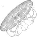
图2为从左心耳口方向看塞子式左心耳封堵器在左心耳中的位置示意图。 Fig. 2 is a schematic diagram of the position of the plug-type left atrial appendage occluder in the left atrial appendage viewed from the direction of the left atrial appendage opening. the
图3为塞盘式左心耳封堵器在心脏及左心耳解剖结构中的位置示意图。 Fig. 3 is a schematic diagram of the position of the disc-type left atrial appendage occluder in the anatomical structure of the heart and the left atrial appendage. the
图4为本发明左心耳封堵器在心脏及左心耳解剖结构中的位置示意图,其中固定架固定在左心耳较深的部位。 Fig. 4 is a schematic diagram of the position of the left atrial appendage occluder of the present invention in the anatomical structure of the heart and the left atrial appendage, wherein the fixing frame is fixed at a deeper part of the left atrial appendage. the
图5为本发明左心耳封堵器在心脏及左心耳解剖结构中的位置示意图,其中固定架固定在左心耳较浅的部位。 Fig. 5 is a schematic diagram of the position of the left atrial appendage occluder of the present invention in the anatomical structure of the heart and the left atrial appendage, wherein the fixing frame is fixed on the shallower part of the left atrial appendage. the
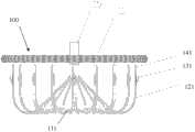
图6为本发明左心耳封堵器的第一实施例的主视图。 Fig. 6 is a front view of the first embodiment of the left atrial appendage occluder of the present invention. the
图7为本发明左心耳封堵器的第一实施例的俯视图。 Fig. 7 is a top view of the first embodiment of the left atrial appendage occluder of the present invention. the
图8为本发明左心耳封堵器的第一实施例的立体图。 Fig. 8 is a perspective view of the first embodiment of the left atrial appendage occluder of the present invention. the
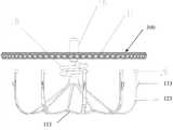
图9为本发明左心耳封堵器的第二实施例的主视图。 Fig. 9 is a front view of the second embodiment of the left atrial appendage occluder of the present invention. the
图10为本发明左心耳封堵器的第二实施例的立体图。 Fig. 10 is a perspective view of the second embodiment of the left atrial appendage occluder of the present invention. the
图11为图10的局部放大图。 FIG. 11 is a partially enlarged view of FIG. 10 . the
图12为本发明左心耳封堵器的第三实施例的主视图。 Fig. 12 is a front view of the third embodiment of the left atrial appendage occluder of the present invention. the
图13为本发明左心耳封堵器的第三实施例的立体图。 Fig. 13 is a perspective view of a third embodiment of the left atrial appendage occluder of the present invention. the
图14为图13的局部放大图。 FIG. 14 is a partially enlarged view of FIG. 13 . the
图15为图13中的固定架上的支撑杆末端的放大图。 FIG. 15 is an enlarged view of the ends of the support rods on the bracket in FIG. 13 . the
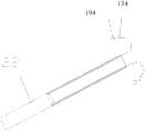
图16为本发明左心耳封堵器的第四实施例的主视图。 Fig. 16 is a front view of the fourth embodiment of the left atrial appendage occluder of the present invention. the
图17为本发明左心耳封堵器的第四实施例的立体图。 Fig. 17 is a perspective view of the fourth embodiment of the left atrial appendage occluder of the present invention. the
图18为图17的局部放大图。 FIG. 18 is a partially enlarged view of FIG. 17 . the
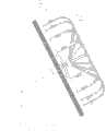
图19为本发明左心耳封堵器的第四实施例的固定架进鞘管和出鞘管时的支撑杆末端的运动方向示意图。 Fig. 19 is a schematic diagram of the moving direction of the end of the support rod when the fixing frame enters and exits the sheath of the fourth embodiment of the left atrial appendage occluder of the present invention. the
图20为本发明左心耳封堵器的第四实施例的固定架刚进鞘管或出鞘管的状态示意图。 Fig. 20 is a schematic diagram of the state of the fixation frame of the fourth embodiment of the left atrial appendage occluder of the present invention just entering or exiting the sheath. the
图21为本发明左心耳封堵器的第四实施例的固定架的大部分支撑杆已经进鞘管或出鞘管的状态示意图。 Fig. 21 is a schematic diagram of the state where most of the support rods of the fixing frame of the fourth embodiment of the left atrial appendage occluder of the present invention have been put into or out of the sheath. the
图22为本发明左心耳封堵器的第四实施例的固定架的支撑杆末端准备进鞘管或出鞘管的状态示意图。 Fig. 22 is a schematic diagram of the state in which the end of the support rod of the fixing frame of the fourth embodiment of the left atrial appendage occluder of the present invention is ready to be put into or out of the sheath. the
图23为本发明左心耳封堵器的第四实施例的支撑杆末端在鞘管中的状态示意图。 Fig. 23 is a schematic diagram of the state of the end of the support rod in the sheath of the fourth embodiment of the left atrial appendage occluder of the present invention. the
图24为本发明左心耳封堵器的第五实施例的固定架刚进鞘管或出鞘管的状态示意图。 Fig. 24 is a schematic view showing the status of the fixing frame of the fifth embodiment of the left atrial appendage occluder of the present invention just entering or exiting the sheath. the
图25为本发明左心耳封堵器的第五实施例的固定架的大部分支撑杆已经进鞘管或支撑杆的小部分将要出鞘管的状态示意图。 Fig. 25 is a schematic diagram of a state in which most of the support rods of the fixing frame of the fifth embodiment of the left atrial appendage occluder of the present invention have been inserted into the sheath or a small part of the support rods is about to come out of the sheath. the
图26为本发明左心耳封堵器的第五实施例的固定架的支撑杆末端附近的U形弯曲部准备进鞘管或已经出鞘管的状态示意图。 Fig. 26 is a schematic diagram of the state where the U-shaped bent part near the end of the support rod of the fixing frame of the fifth embodiment of the left atrial appendage occluder of the present invention is ready to be inserted into the sheath or has been out of the sheath. the
为了使本发明的目的、技术方案及优点更加清楚明白,以下结合附图及实施例,对本发明进行进一步详细说明。应当理解,此处所描述的具体实施例仅仅用以解释本发明,并不用于限定本发明。 In order to make the object, technical solution and advantages of the present invention clearer, the present invention will be further described in detail below in conjunction with the accompanying drawings and embodiments. It should be understood that the specific embodiments described here are only used to explain the present invention, not to limit the present invention. the
下面将结合附图和多个具体实施例对本发明做进一步详细说明。 The present invention will be further described in detail below in conjunction with the accompanying drawings and multiple specific embodiments. the
第一实施例: First embodiment:
如图6、图7、和图8所示,本发明第一实施例的左心耳封堵器100包括封闭盘11和与该封闭盘11连接的固定架111。其中,该固定架111包括多个相连接的支撑杆121,固定架111是用一根镍钛管切割出多个支撑杆121然后用模具撑开,利用热处理的方式定型成如图6所示的形状。该封闭盘11用镍钛丝通过编织的方式制作成编织网10,利用热处理的方式做成盘状,在两端用套管固定,然后在一端的套管上焊接装上与输送器连接的带螺纹的连接件15,封闭盘11的另一端为固定端,该固定端的套管连接到固定架111的接头16上,在封闭盘11内部用医用缝线缝上阻流膜(PTFE或PET膜),该封闭盘11俯视图参照图7。虽然第一实施例采用九根支撑杆12,但根据力学性能和尺寸规格要求可以选择其它数目,如六根,八根,十二根,以及十六根等。这九根支撑杆121是呈放射状对称排列的,从中心沿斜轴方向张开成伞状,然后通过U形弯折使支撑杆121的末端141基本平行于固定架111的中轴线。每一根支撑杆121在其弯曲部附近分成两个分支,相邻两根支撑杆121的两个分支通过U形弯折再连接成一体,最终汇集到固定架111的接头16上。该接头16在镍钛管的未切割的一端,并且位于固定架111的中心,以构成与该封闭盘11连接的中心端部。在切割时,靠近支撑杆121的末端141的锚刺131也要被切出,利用相应的模具定出该锚刺131的形状,该锚刺131朝向支撑杆121的末端141, 锚刺131的根部在支撑杆121上,该锚刺131的尖端自动向外张开,压缩该锚刺131后,该锚刺131收回到该支撑杆121上。锚刺131的长度适当,既保证足够的固定效果,又不因刺入左心耳的深度过大而增加风险,比如1-2毫米长的锚刺。最后把封闭盘11的固定端和固定架111的接头16焊接起来。该封闭盘11具有很好的柔韧性,而支撑杆121具有一定的变形能力,可以起到一定程度的调节封闭盘11和固定架111的相对位置和相对距离的作用,这样,支撑杆121上的锚刺131朝向封闭盘11,锚刺131便可以固定在左心耳的不同深度位置,同时保证封闭盘11对左心耳口部的密封。 As shown in FIG. 6 , FIG. 7 , and FIG. 8 , the left
第二实施例: The second embodiment:
如图9、图10和图11所示,本发明第二实施例的左心耳封堵器200包括封闭盘11和与该封闭盘11连接的固定架112。该封闭盘11用镍钛丝通过编织的方式编成网状,利用热处理的方式做成盘状,在两端用套管固定,在一端的套管上焊接装上与输送器连接的带螺纹的连接件15,然后在该封闭盘11内部用医用缝线缝上阻流膜(PTFE或PET膜),该封闭盘11的另一端为固定端,该固定端的套管连接到固定架112的中心端部,该中心端部包括柔性接头17,该封闭盘11的俯视图如第一实施例中的图7所示。用镍钛管通过切割然后利用热处理的方式定成固定架112的支撑杆122;在切割时固定架112上的锚刺132也要被切出,利用相应的模具定出锚刺132的形状,锚刺132朝向支撑杆122的末端142;在切割镍钛管时还要切出柔性接头17,该柔性接头17包含一个具有弹性的螺旋状结构,该螺旋结构介于封闭盘11的固定端套管与固定架112的支撑杆122之间,其局部放大后如图11所示。最后把封闭盘11的固定端套管和固定架112的柔性接头17用焊接的方式连接起来。柔性接头17具有更好的变形能力,可以在更大范围内调节封闭盘11和固定架112的相对位置和相对距离,这样,支撑杆122的锚刺132朝向封闭盘11,锚刺132能够更可靠地固定在左心耳的不同深度位置,同时保证封闭盘11对左心耳口部的密封。 As shown in FIG. 9 , FIG. 10 and FIG. 11 , the left
第三实施例: The third embodiment:
如图12至图15所示,本发明第三实施例的左心耳封堵器300包括封闭盘11和与该封闭盘11连接的固定架113。封闭盘11用镍钛丝通过编织的方式编成网状,利用热处理的方式做成盘状,在两端用套管固定,在一端的套管上焊接装上与输送器连接的带螺纹的连接件15,然后在该封闭盘11内部用医用缝线缝上阻流膜(PTFE或PET膜),该封闭盘11的另一端为固定端,该固定端的套管还与该固定架113的中心端部连接,该中心端部包括一根连接弹簧18,该封闭盘11的俯视图如第一实施例中的图7所示。用镍钛管通过切割然后利用热处理的方式定成固定架113的支撑杆123,利用热熔的方式把支撑杆123的末端做成球头19,如图15所示,这可以减少封堵器对左心耳的损伤;在切割时该固定架113上的锚刺133也要被切出,利用相应的模具定出锚刺133的形状,锚刺133朝向支撑杆123的末端143;切割镍钛管时,固定架113的远离球头19的另一端保留很短一段镍钛管,防止支撑杆123在这一端相互分开。连接弹簧18利用单根或多根镍钛丝通过热处理的方式形成螺旋状结构,其局部放大后如图14所示。最后把封闭盘11和固定架113通过连接弹簧18连接起来,连接弹簧18的一端和封闭盘11的固定端套管焊接,连接弹簧18的另一端和固定架113的保留镍钛管的一端焊接。连接弹簧18具有比较强的变形能力,可以在很大程度上调节封闭盘11和固定架113的相对位置和相对距离,这样,支撑杆123的锚刺133朝向封闭盘11,锚刺133能够更可靠地固定在左心耳的不同深度位置,同时保证封闭盘11对左心耳口部的密封。 As shown in FIGS. 12 to 15 , the left
第四实施例: The fourth embodiment:
如图16至图18所示,本发明第四实施例的左心耳封堵器400包括封闭盘11和与封闭盘11连接的固定架114。该封闭盘11用镍钛丝通过编织的方式编成网状,利用热处理的方式做成盘状,在两端用套管固定,在一端的套管上焊接装上与输送器连接的带螺纹的连接件15,然后在该封闭盘11内部用医用缝线缝上阻流膜(PTFE或PET膜),该封闭盘11的另一端为固定端,该固定端的套管还与该固定架113的中心端部连接,该中心端部包括一个多线形柔性件 20,该封闭盘11的俯视图如第一实施例中的图7所示。用镍钛管通过切割然后利用热处理的方式定成固定架114的支撑杆124;利用热熔的方式把支撑杆124的末端做成球头194,如图16所示,这可以减少封堵器对左心耳的损伤;在切割时固定架114上的锚刺134也要被切出,利用相应的模具定出锚刺134的形状,锚刺134朝向支撑杆124的末端144;切割镍钛管时,该固定架114的远离球头194的另一端保留很短一段镍钛管,防止支撑杆124在这一端相互分开。多线形柔性件20利用四根镍钛丝(可以理解,镍钛丝的数目可以少于或多于四根;也可以用其它金属丝,如不锈钢丝;每根镍钛丝也可以换成多根复合的镍钛绳)通过热处理的方式弯曲成如图18中所示的鼓状肋条构造,因为镍钛丝具有超弹性而能将多线形柔性件20的两端间距拉开。当然,多线形柔性件20也可采用具有功能相同的其它已知线形封闭结构,只要每根弹性丝都分别在该结构的两端对称地聚拢固定,并且该结构的两端同时具备以下特点:能够在弹性丝允许的范围内相对移动,在自然状态下保持较短的间距,提供比较稳定的支撑力,在拉力作用下也能延长间距。最后把封闭盘11和固定架114通过多线形柔性件20连接起来,多线形柔性件20的一端和封闭盘11的固定端套管焊接,多线形柔性件20的另一端和固定架114的保留镍钛管的一端焊接。多线形柔性件20具有比较强的变形能力,可以在很大程度上调节封闭盘11和固定架114的相对位置和相对距离,这样,支撑杆124的锚刺134朝向封闭盘11,锚刺134能够更可靠地固定在左心耳的不同深度位置,同时保证封闭盘11对左心耳口部的密封,如图4和图5所示。本发明中的其它实施例的左心耳封堵器在心脏及左心耳解剖结构中的位置示意图类似于图4和图5。 As shown in FIG. 16 to FIG. 18 , the left
如图19至图23所示,该固定架114的进入鞘管22和从鞘管22里出来的过程具有如下特点:在输送器的连接杆21的作用下,当处于展开状态的固定架114要收入鞘管22中时,支撑杆124的末端沿着图19中所示的A向运动,其进入鞘管22的不同阶段如图20、图21、图22、及图23所示,每个支撑杆124的末端球头194和锚刺134会做一个翻转;当处于鞘管22中的固定架114要被 推出鞘管22时,支撑杆124的末端沿着图19中所示的B向运动,和进入鞘管22的各个阶段相反,其从鞘管22里出来的不同阶段会按如图23、图22、图21、及图20的顺序依次进行,每个支撑杆124的末端球头194和锚刺134也会做与进鞘管相反的一个翻转。这样的设计,既可以使刺入左心耳壁的锚刺134朝向左心耳口部而有利于防止固定架114脱落,需要回收该左心耳封堵器400时,锚刺134也能反转方向而不会损伤左心耳并能顺利地进入鞘管22中。因此,本实施例的左心耳封堵器400可保证固定架114在左心耳中的良好可重复定位性,即保证整个左心耳封堵器的良好可重复定位性,同时减少器械对左心耳的损伤,也使得该器械适用于更小的鞘管以方便手术操作。 As shown in Figures 19 to 23, the process of entering the
第五实施例: The fifth embodiment:
如图24至图26所示,以第三实施例或第四实施例为基础,第五实施例与上述第三实施例或第四实施例的不同之处在于固定架,第五实施例的固定架115与第三实施例或第四实施例的固定架大致相似,其区别在于:该第五实施例的固定架115的每一个支撑杆125上增加一个U形弯曲部235,该U形弯曲部235位于支撑杆125末端的球头195与锚刺135之间。本实施例的一部分固定架115收缩进入鞘管22,而支撑杆125的末端保持在鞘管22之外的状态如图24所示。此时,锚刺135基本上指向封闭盘11(已收缩进鞘管22之内)并略微倾向轴外侧,U形弯曲部235从锚刺135附近开始朝固定架115的中心弯曲,小球195固定在U形弯曲部235的末端。支撑杆125的末端较硬,对左心耳的接触部位有不利的刺激,因此在支撑杆125上增加U形弯曲部235,使支撑杆125的末端与左心耳脱离接触,更大程度地减少在左心耳中张开的封堵器对左心耳的损伤。在制作固定架115时,利用固定架115的定形模具,通过热处理的方式,将支撑杆125上的一段直接加工成一个U形弯曲部235。 As shown in Figure 24 to Figure 26, based on the third embodiment or the fourth embodiment, the difference between the fifth embodiment and the above-mentioned third embodiment or the fourth embodiment lies in the fixing frame, the fifth embodiment The fixed
本实施例的固定架115进出鞘管22如图24、图25、图26及图22、图23所示,具有如下特点:在输送器的连接杆21的作用下,当处于展开状态的固定架115要收入鞘管22中时,支撑杆125的末端会沿着图24中所示的C向运动, 其进鞘管22的不同阶段依顺序如图24、图25、图26、图22、及图23所示,每个支撑杆125的末端球头195和锚刺135都会翻转,末端球头195的翻转幅度要大于锚刺135的翻转幅度;当处于鞘管22中的固定架115要被推出鞘管22时,支撑杆125的末端会沿着沿图24中所示的D向运动,和进鞘管22的各个阶段相反,其出鞘管22的不同阶段会按如图23、图22、图26、图25、及图24的顺序进行,每个支撑杆125的末端球头195和锚刺135也会做与进鞘管22相反的翻转,末端球头195的翻转幅度要大于锚刺135的翻转幅度。这样的设计使本实施例具有更多优点,该固定架115的支撑杆125上的锚刺135具有与前述实施例相同的结构和技术效果,而支撑杆125末端附近的U形弯曲部235能更好地避免支撑杆末端损伤左心耳。 As shown in Fig. 24, Fig. 25, Fig. 26 and Fig. 22 and Fig. 23, the fixing
第五实施例的固定架115的支撑杆125末端附近的U形弯曲部235被拉直的状态与图22所示的相同,支撑杆125末端完全在鞘管22中的状态与图23所示的相同。 The
综上所述,该左心耳封堵器包括具有一定的弹性且内装有薄膜的封闭盘及包含多个支撑杆的固定架直接连接而成;或者包括具有一定弹性且内装有薄膜的封闭盘及通过柔性连接结构与该封闭盘连接的且具有多个支撑杆的固定架,整体结构的稳定性较好;该支撑杆上带有的锚刺可随支撑杆做180°翻转,可以增强锚刺的固定力,减小锚刺在回收封堵器时对左心耳的损伤,还有利于器械的重复定位,可适应多种结构的左心耳,实现稳定定位;支撑杆的末端可以实现180°或360°翻转;支撑杆末端的球头保证固定架的顺利定位和防止支撑杆的末端刺破左心耳;支撑杆末端附近的U形弯曲部进一步减小封堵器对左心耳的损伤;柔性连接结构可是螺旋结构,也可以是多线形结构,保证密封盘和固定架的相对位置和相对距离的有效调节,可适应多种结构左心耳的不同深度的定位需求。 To sum up, the left atrial appendage occluder includes a closure disc with a certain degree of elasticity and a film inside and a fixing frame comprising a plurality of support rods directly connected; or a closure disc with a certain degree of elasticity and a film inside and The fixed frame connected with the closed plate through a flexible connection structure and has multiple support rods has better stability of the overall structure; the anchor thorns on the support rods can be turned 180° with the support rods, which can strengthen the anchor thorns It can reduce the damage of the anchor thorn to the left atrial appendage when recovering the occluder, and is also conducive to the repeated positioning of the device, which can adapt to various structures of the left atrial appendage and achieve stable positioning; the end of the support rod can be realized at 180° or 360° flip; the ball head at the end of the support rod ensures the smooth positioning of the fixation frame and prevents the end of the support rod from piercing the left atrial appendage; the U-shaped bending part near the end of the support rod further reduces the damage of the occluder to the left atrial appendage; flexible connection The structure can be a helical structure or a multi-linear structure, which ensures the effective adjustment of the relative position and relative distance between the sealing disc and the fixing frame, and can adapt to the positioning requirements of different depths of the left atrial appendage of various structures. the
因此,本发明具有以下优点: Therefore, the present invention has the following advantages:
1、该左心耳封堵器结构稳定,最大限度适应左心耳腔体的多种结构和多种 尺寸。 1. The left atrial appendage occluder has a stable structure and can adapt to various structures and sizes of the cavity of the left atrial appendage to the greatest extent. the
2、保证在左心耳腔壁上更加稳定的定位和在左心耳口的更加严密的密封,兼顾定位和密封两个关键效果之间的平衡。 2. To ensure a more stable positioning on the wall of the left atrial appendage and a tighter sealing on the opening of the left atrial appendage, taking into account the balance between the two key effects of positioning and sealing. the
3、该左心耳封堵器容易重复定位,在脱离输送器之前还可回收;手术操作时,可以根据病人左心耳实际的形态和尺寸选定定位区,不必因器械的局限而选定不合适的定位区,降低手术的风险。 3. The left atrial appendage occluder is easy to be positioned repeatedly, and it can be recovered before it is separated from the conveyor; during operation, the positioning area can be selected according to the actual shape and size of the patient's left atrial appendage, and it is not necessary to choose an inappropriate one due to the limitations of the device The positioning area reduces the risk of surgery. the
4、操作步骤简单顺畅,最大限度地减少医生的重复定位的次数,减少对病人的损伤。 4. The operation steps are simple and smooth, which minimizes the number of repeated positioning by the doctor and reduces the damage to the patient. the
5、该左心耳封堵器能够匹配较小的鞘管,减少鞘管对病人血管壁的损伤。 5. The left atrial appendage occluder can be matched with a smaller sheath to reduce the damage of the sheath to the patient's blood vessel wall. the
以上所述仅为本发明的较佳实施例而已,并不用以限制本发明,凡在本发明的精神和原则之内所作的任何修改、等同替换和改进等,均应包含在本发明的保护范围之内。 The above descriptions are only preferred embodiments of the present invention, and are not intended to limit the present invention. Any modifications, equivalent replacements and improvements made within the spirit and principles of the present invention should be included in the protection of the present invention. within range. the
the
Claims (14)
Translated fromChinesePriority Applications (4)
| Application Number | Priority Date | Filing Date | Title |
|---|---|---|---|
| CN201110146287.5ACN102805654B (en) | 2011-06-01 | 2011-06-01 | Occluder for left auricle |
| US14/122,794US9808253B2 (en) | 2011-06-01 | 2012-05-25 | Left atrial appendage occluder |
| EP12793153.3AEP2716237B1 (en) | 2011-06-01 | 2012-05-25 | Left atrial appendage occluder |
| PCT/CN2012/076124WO2012163257A1 (en) | 2011-06-01 | 2012-05-25 | Left atrial appendage occluder |
Applications Claiming Priority (1)
| Application Number | Priority Date | Filing Date | Title |
|---|---|---|---|
| CN201110146287.5ACN102805654B (en) | 2011-06-01 | 2011-06-01 | Occluder for left auricle |
Publications (2)
| Publication Number | Publication Date |
|---|---|
| CN102805654A CN102805654A (en) | 2012-12-05 |
| CN102805654Btrue CN102805654B (en) | 2014-04-02 |
Family
ID=47229646
Family Applications (1)
| Application Number | Title | Priority Date | Filing Date |
|---|---|---|---|
| CN201110146287.5AActiveCN102805654B (en) | 2011-06-01 | 2011-06-01 | Occluder for left auricle |
Country Status (4)
| Country | Link |
|---|---|
| US (1) | US9808253B2 (en) |
| EP (1) | EP2716237B1 (en) |
| CN (1) | CN102805654B (en) |
| WO (1) | WO2012163257A1 (en) |
Families Citing this family (100)
| Publication number | Priority date | Publication date | Assignee | Title |
|---|---|---|---|---|
| EP2460476B1 (en)* | 2007-04-16 | 2020-11-25 | Occlutech Holding AG | Occluder for closing a cardiac auricle and manufacturing method therefor |
| US9186152B2 (en) | 2010-11-12 | 2015-11-17 | W. L. Gore & Associates, Inc. | Left atrial appendage occlusive devices |
| US9744033B2 (en) | 2011-04-01 | 2017-08-29 | W.L. Gore & Associates, Inc. | Elastomeric leaflet for prosthetic heart valves |
| US9554806B2 (en) | 2011-09-16 | 2017-01-31 | W. L. Gore & Associates, Inc. | Occlusive devices |
| KR20150073994A (en) | 2012-09-26 | 2015-07-01 | 엘지전자 주식회사 | Method and apparatus for gaining access in wireless lan system |
| CN103099652B (en)* | 2013-02-19 | 2015-08-12 | 湖南埃普特医疗器械有限公司 | A kind of left atrial appendage occlusion device and a kind of induction system |
| WO2014127641A1 (en)* | 2013-02-19 | 2014-08-28 | 湖南埃普特医疗器械有限公司 | Left atrial appendage plugging device and delivery system |
| JP6423851B2 (en) | 2013-03-13 | 2018-11-14 | アーロン・ヴィ・カプラン | Device for emptying the left atrial appendage |
| US11399842B2 (en) | 2013-03-13 | 2022-08-02 | Conformal Medical, Inc. | Devices and methods for excluding the left atrial appendage |
| US10617425B2 (en) | 2014-03-10 | 2020-04-14 | Conformal Medical, Inc. | Devices and methods for excluding the left atrial appendage |
| US11911258B2 (en) | 2013-06-26 | 2024-02-27 | W. L. Gore & Associates, Inc. | Space filling devices |
| CN103598902B (en)* | 2013-11-14 | 2017-01-25 | 先健科技(深圳)有限公司 | Left aurcle plugging device |
| US9730701B2 (en)* | 2014-01-16 | 2017-08-15 | Boston Scientific Scimed, Inc. | Retrieval wire centering device |
| PT3125780T (en) | 2014-03-31 | 2018-04-09 | Jitmed Sp Z O O | Left atrial appendage occlusion device |
| US20170095256A1 (en)* | 2014-06-11 | 2017-04-06 | Occlutech Holding Ag | Left Atrial Appendage Occluder |
| CN104107072A (en)* | 2014-07-29 | 2014-10-22 | 孙伟 | Double umbrella type left auricle sealing device |
| CN105326536A (en)* | 2014-08-12 | 2016-02-17 | 徐州亚太科技有限公司 | Percutaneous left atrial appendage occluder |
| ES2794632T3 (en) | 2014-09-12 | 2020-11-18 | Carag Ag | Occluder |
| CN105476683A (en)* | 2014-09-16 | 2016-04-13 | 徐州亚太科技有限公司 | Combined left aurcle occluding device |
| CN105434082A (en)* | 2014-09-16 | 2016-03-30 | 徐州亚太科技有限公司 | Left auricle plugging device |
| CN104274224B (en)* | 2014-09-29 | 2017-01-25 | 上海形状记忆合金材料有限公司 | Left atrial appendage occlusion device |
| CN104352261B (en)* | 2014-10-13 | 2017-11-03 | 深圳市科奕顿生物医疗科技有限公司 | Occluder for left auricle |
| CN104352260B (en)* | 2014-10-13 | 2017-11-21 | 深圳市科奕顿生物医疗科技有限公司 | Left atrial appendage occlusion system |
| EP3028652A1 (en)* | 2014-12-03 | 2016-06-08 | Peter Osypka Stiftung | Closure device suitable for closing the atrial appendage |
| CN105796148B (en)* | 2014-12-31 | 2018-06-05 | 先健科技(深圳)有限公司 | Occluder for left auricle |
| CN104688292B (en)* | 2015-02-15 | 2017-08-25 | 上海形状记忆合金材料有限公司 | A kind of left atrial appendage occlusion device and plugging system |
| CA2986047C (en) | 2015-05-14 | 2020-11-10 | W. L. Gore & Associates, Inc. | Devices and methods for occlusion of an atrial appendage |
| CN104856741B (en)* | 2015-06-15 | 2017-11-10 | 同济大学附属第十人民医院 | One kind is through conduit left atrial appendage occlusion system |
| CN105147350A (en)* | 2015-10-08 | 2015-12-16 | 上海形状记忆合金材料有限公司 | Self-adaptive plugging device |
| CN105496490B (en)* | 2015-12-10 | 2019-01-04 | 李毅刚 | A kind of occluder for left auricle and its air navigation aid |
| RU2738426C1 (en)* | 2015-12-29 | 2020-12-14 | Шэньчжэнь Кид Биомедикал Текнолоджи Ко.Лтд | Left atrial appendage occluder (versions) |
| CN106901792B (en) | 2015-12-29 | 2019-11-01 | 深圳市科奕顿生物医疗科技有限公司 | Occluder for left auricle |
| CN106923886B (en)* | 2015-12-31 | 2022-04-22 | 先健科技(深圳)有限公司 | Left atrial appendage occluder |
| CN106923885B (en)* | 2015-12-31 | 2019-07-09 | 先健科技(深圳)有限公司 | Occluder for left auricle |
| CN106923883B (en)* | 2015-12-31 | 2019-09-03 | 先健科技(深圳)有限公司 | Left atrial appendage occluder |
| CN106923884B (en)* | 2015-12-31 | 2018-12-21 | 先健科技(深圳)有限公司 | Occluder for left auricle |
| CN105662516A (en)* | 2016-03-03 | 2016-06-15 | 上海普实医疗器械科技有限公司 | Left aurcle plugging device |
| CN107233117B (en)* | 2016-03-28 | 2019-10-25 | 上海微创医疗器械(集团)有限公司 | Occluder for left auricle |
| CN107233115B (en)* | 2016-03-28 | 2020-01-24 | 上海微创医疗器械(集团)有限公司 | Left auricle plugging device |
| CN107233116B (en)* | 2016-03-28 | 2021-03-02 | 上海微创医疗器械(集团)有限公司 | Left auricle plugging device |
| CN106994030B (en)* | 2016-06-15 | 2020-03-10 | 先健科技(深圳)有限公司 | Left auricle plugging device |
| US10383725B2 (en) | 2016-08-11 | 2019-08-20 | 4C Medical Technologies, Inc. | Heart chamber prosthetic valve implant with base, mesh and dome sections with single chamber anchoring for preservation, supplementation and/or replacement of native valve function |
| CN106466196B (en)* | 2016-09-22 | 2023-11-07 | 杭州德诺电生理医疗科技有限公司 | A split left atrial appendage occlusion device |
| WO2018081466A2 (en) | 2016-10-27 | 2018-05-03 | Conformal Medical, Inc. | Devices and methods for excluding the left atrial appendage |
| US11426172B2 (en) | 2016-10-27 | 2022-08-30 | Conformal Medical, Inc. | Devices and methods for excluding the left atrial appendage |
| WO2018089311A1 (en) | 2016-11-08 | 2018-05-17 | Cardiac Pacemakers, Inc | Implantable medical device for atrial deployment |
| US10653523B2 (en) | 2017-01-19 | 2020-05-19 | 4C Medical Technologies, Inc. | Systems, methods and devices for delivery systems, methods and devices for implanting prosthetic heart valves |
| US10561495B2 (en) | 2017-01-24 | 2020-02-18 | 4C Medical Technologies, Inc. | Systems, methods and devices for two-step delivery and implantation of prosthetic heart valve |
| US12029647B2 (en) | 2017-03-07 | 2024-07-09 | 4C Medical Technologies, Inc. | Systems, methods and devices for prosthetic heart valve with single valve leaflet |
| US11812968B2 (en)* | 2017-05-10 | 2023-11-14 | Lifetech Scientific (Shenzhen) Co. Ltd. | Left atrial appendage occluder |
| EP3403596A1 (en)* | 2017-05-16 | 2018-11-21 | Universitätsklinikum Jena | Implantation and anchorage system for an atrial occluder |
| CN208958224U (en)* | 2017-05-23 | 2019-06-11 | 杭州诺茂医疗科技有限公司 | A left atrial appendage occluder with staggered connection structure |
| CN108938035B (en)* | 2017-05-23 | 2025-09-05 | 杭州德诺电生理医疗科技有限公司 | Left atrial appendage occluder with improved connection method |
| CN108938037B (en)* | 2017-05-27 | 2021-09-24 | 上海佐心医疗科技有限公司 | Left auricle plugging device |
| US12036113B2 (en) | 2017-06-14 | 2024-07-16 | 4C Medical Technologies, Inc. | Delivery of heart chamber prosthetic valve implant |
| CN107126241B (en)* | 2017-06-16 | 2023-08-08 | 宁波迪创医疗科技有限公司 | Biological cavity anchoring device capable of being completely recovered and repeatedly released |
| CN107137122A (en)* | 2017-07-01 | 2017-09-08 | 吕纬岩 | A kind of adaptable occluder for left auricle |
| CN109419548A (en)* | 2017-08-21 | 2019-03-05 | 上海普实医疗器械科技有限公司 | Occluder for left auricle and its manufacturing method |
| EP3459469A1 (en) | 2017-09-23 | 2019-03-27 | Universität Zürich | Medical occluder device |
| US12402885B2 (en) | 2017-09-23 | 2025-09-02 | Universität Zürich | Medical occlusion device |
| US11173023B2 (en) | 2017-10-16 | 2021-11-16 | W. L. Gore & Associates, Inc. | Medical devices and anchors therefor |
| US11191547B2 (en) | 2018-01-26 | 2021-12-07 | Syntheon 2.0, LLC | Left atrial appendage clipping device and methods for clipping the LAA |
| US11510678B2 (en)* | 2018-03-15 | 2022-11-29 | St. Jude Medical, Cardiology Division, Inc. | Self-expanding ventricular partitioning device including anchor |
| US11020124B1 (en) | 2018-07-05 | 2021-06-01 | Henry Copeland | Left atrial appendage closure device and method |
| US11857441B2 (en) | 2018-09-04 | 2024-01-02 | 4C Medical Technologies, Inc. | Stent loading device |
| US12144508B2 (en) | 2019-02-08 | 2024-11-19 | Conformal Medical, Inc. | Devices and methods for excluding the left atrial appendage |
| US12268394B2 (en) | 2019-02-08 | 2025-04-08 | Conformal Medical, Inc. | Devices and methods for excluding the left atrial appendage |
| CN113873957B (en) | 2019-03-25 | 2025-06-24 | 拉米纳公司 | Devices and systems for treating the left atrial appendage |
| US11452628B2 (en) | 2019-04-15 | 2022-09-27 | 4C Medical Technologies, Inc. | Loading systems for collapsible prosthetic heart valve devices and methods thereof |
| US10925615B2 (en) | 2019-05-03 | 2021-02-23 | Syntheon 2.0, LLC | Recapturable left atrial appendage clipping device and methods for recapturing a left atrial appendage clip |
| CN110420044B (en)* | 2019-06-28 | 2020-12-18 | 先健科技(深圳)有限公司 | Blocking device |
| CN114126540A (en) | 2019-07-17 | 2022-03-01 | 波士顿科学医学有限公司 | Continuously covered left atrial appendage implant |
| EP4563099A3 (en) | 2019-08-30 | 2025-08-06 | Boston Scientific Scimed, Inc. | Left atrial appendage implant with sealing disk |
| JP7531236B2 (en) | 2019-09-26 | 2024-08-09 | ウニベルシタット チューリッヒ | Left atrial appendage closure device |
| CN112244927B (en)* | 2019-11-04 | 2025-07-15 | 深圳市科奕顿生物医疗科技有限公司 | Intraluminal implantable medical devices |
| CN113116445B (en)* | 2019-12-31 | 2022-10-21 | 先健科技(深圳)有限公司 | Blocking device |
| US11534175B2 (en) | 2020-01-28 | 2022-12-27 | Medtronic, Inc. | Modular left atrial appendage closure |
| US12133797B2 (en) | 2020-01-31 | 2024-11-05 | 4C Medical Technologies, Inc. | Prosthetic heart valve delivery system: paddle attachment feature |
| US11931253B2 (en) | 2020-01-31 | 2024-03-19 | 4C Medical Technologies, Inc. | Prosthetic heart valve delivery system: ball-slide attachment |
| US12053375B2 (en) | 2020-03-05 | 2024-08-06 | 4C Medical Technologies, Inc. | Prosthetic mitral valve with improved atrial and/or annular apposition and paravalvular leakage mitigation |
| US11992403B2 (en) | 2020-03-06 | 2024-05-28 | 4C Medical Technologies, Inc. | Devices, systems and methods for improving recapture of prosthetic heart valve device with stent frame having valve support with inwardly stent cells |
| CN113440200A (en)* | 2020-03-24 | 2021-09-28 | 上海佐心医疗科技有限公司 | Support for blocking body cavity and left auricle blocking device |
| WO2021195085A1 (en) | 2020-03-24 | 2021-09-30 | Boston Scientific Scimed, Inc. | Medical system for treating a left atrial appendage |
| US12303116B2 (en) | 2020-03-24 | 2025-05-20 | Laminar, Inc. | Devices, systems, and methods for occluding cavities within the body |
| WO2021263145A1 (en) | 2020-06-25 | 2021-12-30 | Squadra Lifesciences, Inc. | Methods and apparatus for occluding the left atrial appendage |
| CN111643145B (en)* | 2020-06-28 | 2021-07-20 | 哈尔滨工业大学 | A kind of left atrial appendage occluder and preparation method thereof |
| CN112155627B (en)* | 2020-07-28 | 2025-07-25 | 宁波迪创医疗科技有限公司 | Left auricle plugging device with bionic micro-thorn attachment structure |
| EP3949876B1 (en)* | 2020-08-03 | 2024-09-18 | St. Jude Medical, Cardiology Division, Inc. | Devices for the treatment of vascular abnormalities |
| US12426886B2 (en) | 2020-11-23 | 2025-09-30 | Eric William Schneeberger | Atrial appendage excluder |
| JP7627761B2 (en) | 2020-11-30 | 2025-02-06 | ボストン サイエンティフィック サイムド,インコーポレイテッド | Implantable passive mean pressure sensor |
| CN114617602A (en)* | 2020-12-10 | 2022-06-14 | 先健科技(深圳)有限公司 | Plugging device |
| US12383201B2 (en) | 2021-02-03 | 2025-08-12 | Boston Scientific Scimed, Inc. | Medical system for treating a left atrial appendage |
| IT202100008411A1 (en) | 2021-04-02 | 2022-10-02 | Riccardo Laurenti | LEFT ATRIAL AUCTION OCCLUSOR |
| EP4358872A1 (en) | 2021-06-22 | 2024-05-01 | Boston Scientific Scimed, Inc. | Left atrial appendage implant |
| CN117615720A (en) | 2021-07-08 | 2024-02-27 | 波士顿科学医学有限公司 | Left auricle closing device |
| WO2023038929A1 (en) | 2021-09-08 | 2023-03-16 | Boston Scientific Scimed, Inc. | Occlusive implant with multi-sharpness split tip soft tissue anchors |
| CN114376644B (en)* | 2021-12-07 | 2025-09-30 | 杭州堃博生物科技有限公司 | One-way valve device for use in the airway |
| CN113974716B (en)* | 2021-12-28 | 2022-06-21 | 先健科技(深圳)有限公司 | Blocking device |
| CN115956962A (en)* | 2023-03-02 | 2023-04-14 | 徐州亚太科技有限公司 | A patent foramen ovale occluder |
| CN118717208A (en)* | 2024-06-30 | 2024-10-01 | 武汉唯柯医疗科技有限公司 | Occluder and occluder input system |
Citations (3)
| Publication number | Priority date | Publication date | Assignee | Title |
|---|---|---|---|---|
| CN1342056A (en)* | 1998-11-06 | 2002-03-27 | 阿普利瓦医学股份有限公司 | Methods and devices for left atrial appendage occlusion |
| CN1711978A (en)* | 2004-06-25 | 2005-12-28 | 深圳市先健科技股份有限公司 | Latching of left auricular appendix and conveyor thereof |
| CN202143640U (en)* | 2011-06-01 | 2012-02-15 | 先健科技(深圳)有限公司 | Left atrial appendage occluder |
Family Cites Families (14)
| Publication number | Priority date | Publication date | Assignee | Title |
|---|---|---|---|---|
| US7128073B1 (en)* | 1998-11-06 | 2006-10-31 | Ev3 Endovascular, Inc. | Method and device for left atrial appendage occlusion |
| US7044134B2 (en)* | 1999-11-08 | 2006-05-16 | Ev3 Sunnyvale, Inc | Method of implanting a device in the left atrial appendage |
| US8388672B2 (en) | 1999-08-09 | 2013-03-05 | Cardiokinetix, Inc. | System for improving cardiac function by sealing a partitioning membrane within a ventricle |
| EP1309289A2 (en)* | 2000-08-18 | 2003-05-14 | Atritech, Inc. | Expandable implant devices for filtering blood flow from atrial appendages |
| IL157732A0 (en)* | 2001-03-08 | 2004-03-28 | Atritech Inc | Atrial filter implants |
| US20030181942A1 (en)* | 2002-01-25 | 2003-09-25 | Sutton Gregg S. | Atrial appendage blood filtration systems |
| US7972359B2 (en)* | 2005-09-16 | 2011-07-05 | Atritech, Inc. | Intracardiac cage and method of delivering same |
| WO2008150346A1 (en)* | 2007-05-31 | 2008-12-11 | Rex Medical, L.P. | Closure device for left atrial appendage |
| US20090171386A1 (en)* | 2007-12-28 | 2009-07-02 | Aga Medical Corporation | Percutaneous catheter directed intravascular occlusion devices |
| CA2765682C (en)* | 2009-06-17 | 2018-07-24 | Coherex Medical, Inc. | Medical device for modification of left atrial appendage and related systems and methods |
| US20110054515A1 (en)* | 2009-08-25 | 2011-03-03 | John Bridgeman | Device and method for occluding the left atrial appendage |
| EP2528646A4 (en)* | 2010-01-29 | 2017-06-28 | DC Devices, Inc. | Devices and systems for treating heart failure |
| EP2672927A4 (en)* | 2011-02-10 | 2014-08-20 | Atrial Innovations Inc | EARLY APPENDIX OCCLUSION AND TREATMENT OF ARRHYTHMIA |
| US8758389B2 (en)* | 2011-11-18 | 2014-06-24 | Aga Medical Corporation | Devices and methods for occluding abnormal openings in a patient's vasculature |
- 2011
- 2011-06-01CNCN201110146287.5Apatent/CN102805654B/enactiveActive
- 2012
- 2012-05-25USUS14/122,794patent/US9808253B2/enactiveActive
- 2012-05-25WOPCT/CN2012/076124patent/WO2012163257A1/enactiveApplication Filing
- 2012-05-25EPEP12793153.3Apatent/EP2716237B1/enactiveActive
Patent Citations (3)
| Publication number | Priority date | Publication date | Assignee | Title |
|---|---|---|---|---|
| CN1342056A (en)* | 1998-11-06 | 2002-03-27 | 阿普利瓦医学股份有限公司 | Methods and devices for left atrial appendage occlusion |
| CN1711978A (en)* | 2004-06-25 | 2005-12-28 | 深圳市先健科技股份有限公司 | Latching of left auricular appendix and conveyor thereof |
| CN202143640U (en)* | 2011-06-01 | 2012-02-15 | 先健科技(深圳)有限公司 | Left atrial appendage occluder |
Also Published As
| Publication number | Publication date |
|---|---|
| CN102805654A (en) | 2012-12-05 |
| EP2716237B1 (en) | 2018-04-04 |
| US20140142612A1 (en) | 2014-05-22 |
| US9808253B2 (en) | 2017-11-07 |
| EP2716237A4 (en) | 2015-05-06 |
| EP2716237A1 (en) | 2014-04-09 |
| WO2012163257A1 (en) | 2012-12-06 |
Similar Documents
| Publication | Publication Date | Title |
|---|---|---|
| CN102805654B (en) | Occluder for left auricle | |
| US11547417B2 (en) | Left atrial appendage occluder | |
| CN202143640U (en) | Left atrial appendage occluder | |
| CN101049267B (en) | medical occlusive device | |
| CN105916454B (en) | Left atrial appendage occluder | |
| CN104352260B (en) | Left atrial appendage occlusion system | |
| CN206792446U (en) | A kind of split type occluder for left auricle | |
| US6206907B1 (en) | Occlusion device with stranded wire support arms | |
| EP1011469B1 (en) | Percutaneous catheter directed occlusion devices | |
| ES2639828T3 (en) | Medical occlusion device | |
| CN103124524B (en) | Braiding medical treatment device and manufacture method thereof | |
| CN114711872B (en) | Left Atrial Appendage Occluder | |
| US7691115B2 (en) | Occlusion device with flexible fabric connector | |
| CN204683686U (en) | A kind of left atrial appendage occlusion device and plugging system | |
| WO2009035610A1 (en) | Occlusion device with centering arm network | |
| CN104274224A (en) | Left atrial appendage occlusion device | |
| CN204181678U (en) | Left atrial appendage occlusion system | |
| WO2018145535A1 (en) | Occlusion device | |
| CN106333725A (en) | Left aurcle plugging device and left aurcle plugging apparatus | |
| CN106137292B (en) | A kind of device for left auricle of heart ligation operation | |
| CN113116409B (en) | Plugging device and plugging device conveying system | |
| CN112971902A (en) | Left auricle occluder and suturing method | |
| CN216060638U (en) | occlusion device | |
| CN209996397U (en) | Left auricle plugging device | |
| CN110613492A (en) | Left auricle plugging device |
Legal Events
| Date | Code | Title | Description |
|---|---|---|---|
| C06 | Publication | ||
| PB01 | Publication | ||
| C10 | Entry into substantive examination | ||
| SE01 | Entry into force of request for substantive examination | ||
| C14 | Grant of patent or utility model | ||
| GR01 | Patent grant |