CN102803754A - Coating agent device and coating device - Google Patents
Coating agent device and coating deviceDownload PDFInfo
- Publication number
- CN102803754A CN102803754ACN2010800251531ACN201080025153ACN102803754ACN 102803754 ACN102803754 ACN 102803754ACN 2010800251531 ACN2010800251531 ACN 2010800251531ACN 201080025153 ACN201080025153 ACN 201080025153ACN 102803754 ACN102803754 ACN 102803754A
- Authority
- CN
- China
- Prior art keywords
- coating agent
- agent device
- mounting base
- needle
- wall
- Prior art date
- Legal status (The legal status is an assumption and is not a legal conclusion. Google has not performed a legal analysis and makes no representation as to the accuracy of the status listed.)
- Granted
Links
Images


Classifications
- F—MECHANICAL ENGINEERING; LIGHTING; HEATING; WEAPONS; BLASTING
- F16—ENGINEERING ELEMENTS AND UNITS; GENERAL MEASURES FOR PRODUCING AND MAINTAINING EFFECTIVE FUNCTIONING OF MACHINES OR INSTALLATIONS; THERMAL INSULATION IN GENERAL
- F16B—DEVICES FOR FASTENING OR SECURING CONSTRUCTIONAL ELEMENTS OR MACHINE PARTS TOGETHER, e.g. NAILS, BOLTS, CIRCLIPS, CLAMPS, CLIPS OR WEDGES; JOINTS OR JOINTING
- F16B35/00—Screw-bolts; Stay-bolts; Screw-threaded studs; Screws; Set screws
- F16B35/007—Removing paint or dirt layers covering the threaded part of nut-like members
- F—MECHANICAL ENGINEERING; LIGHTING; HEATING; WEAPONS; BLASTING
- F16—ENGINEERING ELEMENTS AND UNITS; GENERAL MEASURES FOR PRODUCING AND MAINTAINING EFFECTIVE FUNCTIONING OF MACHINES OR INSTALLATIONS; THERMAL INSULATION IN GENERAL
- F16K—VALVES; TAPS; COCKS; ACTUATING-FLOATS; DEVICES FOR VENTING OR AERATING
- F16K11/00—Multiple-way valves, e.g. mixing valves; Pipe fittings incorporating such valves
- F16K11/10—Multiple-way valves, e.g. mixing valves; Pipe fittings incorporating such valves with two or more closure members not moving as a unit
- B—PERFORMING OPERATIONS; TRANSPORTING
- B05—SPRAYING OR ATOMISING IN GENERAL; APPLYING FLUENT MATERIALS TO SURFACES, IN GENERAL
- B05C—APPARATUS FOR APPLYING FLUENT MATERIALS TO SURFACES, IN GENERAL
- B05C5/00—Apparatus in which liquid or other fluent material is projected, poured or allowed to flow on to the surface of the work
- B—PERFORMING OPERATIONS; TRANSPORTING
- B05—SPRAYING OR ATOMISING IN GENERAL; APPLYING FLUENT MATERIALS TO SURFACES, IN GENERAL
- B05B—SPRAYING APPARATUS; ATOMISING APPARATUS; NOZZLES
- B05B13/00—Machines or plants for applying liquids or other fluent materials to surfaces of objects or other work by spraying, not covered by groups B05B1/00 - B05B11/00
- B05B13/02—Means for supporting work; Arrangement or mounting of spray heads; Adaptation or arrangement of means for feeding work
- B—PERFORMING OPERATIONS; TRANSPORTING
- B05—SPRAYING OR ATOMISING IN GENERAL; APPLYING FLUENT MATERIALS TO SURFACES, IN GENERAL
- B05B—SPRAYING APPARATUS; ATOMISING APPARATUS; NOZZLES
- B05B1/00—Nozzles, spray heads or other outlets, with or without auxiliary devices such as valves, heating means
- B05B1/30—Nozzles, spray heads or other outlets, with or without auxiliary devices such as valves, heating means designed to control volume of flow, e.g. with adjustable passages
- B—PERFORMING OPERATIONS; TRANSPORTING
- B05—SPRAYING OR ATOMISING IN GENERAL; APPLYING FLUENT MATERIALS TO SURFACES, IN GENERAL
- B05B—SPRAYING APPARATUS; ATOMISING APPARATUS; NOZZLES
- B05B11/00—Single-unit hand-held apparatus in which flow of contents is produced by the muscular force of the operator at the moment of use
- B05B11/0005—Components or details
- B05B11/0062—Outlet valves actuated by the pressure of the fluid to be sprayed
- B—PERFORMING OPERATIONS; TRANSPORTING
- B05—SPRAYING OR ATOMISING IN GENERAL; APPLYING FLUENT MATERIALS TO SURFACES, IN GENERAL
- B05B—SPRAYING APPARATUS; ATOMISING APPARATUS; NOZZLES
- B05B12/00—Arrangements for controlling delivery; Arrangements for controlling the spray area
- B—PERFORMING OPERATIONS; TRANSPORTING
- B05—SPRAYING OR ATOMISING IN GENERAL; APPLYING FLUENT MATERIALS TO SURFACES, IN GENERAL
- B05B—SPRAYING APPARATUS; ATOMISING APPARATUS; NOZZLES
- B05B12/00—Arrangements for controlling delivery; Arrangements for controlling the spray area
- B05B12/14—Arrangements for controlling delivery; Arrangements for controlling the spray area for supplying a selected one of a plurality of liquids or other fluent materials or several in selected proportions to a spray apparatus, e.g. to a single spray outlet
- B05B12/149—Arrangements for controlling delivery; Arrangements for controlling the spray area for supplying a selected one of a plurality of liquids or other fluent materials or several in selected proportions to a spray apparatus, e.g. to a single spray outlet characterised by colour change manifolds or valves therefor
- B—PERFORMING OPERATIONS; TRANSPORTING
- B05—SPRAYING OR ATOMISING IN GENERAL; APPLYING FLUENT MATERIALS TO SURFACES, IN GENERAL
- B05C—APPARATUS FOR APPLYING FLUENT MATERIALS TO SURFACES, IN GENERAL
- B05C17/00—Hand tools or apparatus using hand held tools, for applying liquids or other fluent materials to, for spreading applied liquids or other fluent materials on, or for partially removing applied liquids or other fluent materials from, surfaces
- B05C17/005—Hand tools or apparatus using hand held tools, for applying liquids or other fluent materials to, for spreading applied liquids or other fluent materials on, or for partially removing applied liquids or other fluent materials from, surfaces for discharging material from a reservoir or container located in or on the hand tool through an outlet orifice by pressure without using surface contacting members like pads or brushes
- B05C17/015—Hand tools or apparatus using hand held tools, for applying liquids or other fluent materials to, for spreading applied liquids or other fluent materials on, or for partially removing applied liquids or other fluent materials from, surfaces for discharging material from a reservoir or container located in or on the hand tool through an outlet orifice by pressure without using surface contacting members like pads or brushes with pneumatically or hydraulically actuated piston or the like
- B—PERFORMING OPERATIONS; TRANSPORTING
- B05—SPRAYING OR ATOMISING IN GENERAL; APPLYING FLUENT MATERIALS TO SURFACES, IN GENERAL
- B05C—APPARATUS FOR APPLYING FLUENT MATERIALS TO SURFACES, IN GENERAL
- B05C5/00—Apparatus in which liquid or other fluent material is projected, poured or allowed to flow on to the surface of the work
- B05C5/02—Apparatus in which liquid or other fluent material is projected, poured or allowed to flow on to the surface of the work the liquid or other fluent material being discharged through an outlet orifice by pressure, e.g. from an outlet device in contact or almost in contact, with the work
- B05C5/0225—Apparatus in which liquid or other fluent material is projected, poured or allowed to flow on to the surface of the work the liquid or other fluent material being discharged through an outlet orifice by pressure, e.g. from an outlet device in contact or almost in contact, with the work characterised by flow controlling means, e.g. valves, located proximate the outlet
- B05C5/0237—Fluid actuated valves
- F—MECHANICAL ENGINEERING; LIGHTING; HEATING; WEAPONS; BLASTING
- F16—ENGINEERING ELEMENTS AND UNITS; GENERAL MEASURES FOR PRODUCING AND MAINTAINING EFFECTIVE FUNCTIONING OF MACHINES OR INSTALLATIONS; THERMAL INSULATION IN GENERAL
- F16B—DEVICES FOR FASTENING OR SECURING CONSTRUCTIONAL ELEMENTS OR MACHINE PARTS TOGETHER, e.g. NAILS, BOLTS, CIRCLIPS, CLAMPS, CLIPS OR WEDGES; JOINTS OR JOINTING
- F16B21/00—Means for preventing relative axial movement of a pin, spigot, shaft or the like and a member surrounding it; Stud-and-socket releasable fastenings
- F16B21/02—Releasable fastening devices locking by rotation
- F16B21/04—Releasable fastening devices locking by rotation with bayonet catch
- F—MECHANICAL ENGINEERING; LIGHTING; HEATING; WEAPONS; BLASTING
- F16—ENGINEERING ELEMENTS AND UNITS; GENERAL MEASURES FOR PRODUCING AND MAINTAINING EFFECTIVE FUNCTIONING OF MACHINES OR INSTALLATIONS; THERMAL INSULATION IN GENERAL
- F16B—DEVICES FOR FASTENING OR SECURING CONSTRUCTIONAL ELEMENTS OR MACHINE PARTS TOGETHER, e.g. NAILS, BOLTS, CIRCLIPS, CLAMPS, CLIPS OR WEDGES; JOINTS OR JOINTING
- F16B7/00—Connections of rods or tubes, e.g. of non-circular section, mutually, including resilient connections
- F16B7/18—Connections of rods or tubes, e.g. of non-circular section, mutually, including resilient connections using screw-thread elements
- F—MECHANICAL ENGINEERING; LIGHTING; HEATING; WEAPONS; BLASTING
- F16—ENGINEERING ELEMENTS AND UNITS; GENERAL MEASURES FOR PRODUCING AND MAINTAINING EFFECTIVE FUNCTIONING OF MACHINES OR INSTALLATIONS; THERMAL INSULATION IN GENERAL
- F16B—DEVICES FOR FASTENING OR SECURING CONSTRUCTIONAL ELEMENTS OR MACHINE PARTS TOGETHER, e.g. NAILS, BOLTS, CIRCLIPS, CLAMPS, CLIPS OR WEDGES; JOINTS OR JOINTING
- F16B7/00—Connections of rods or tubes, e.g. of non-circular section, mutually, including resilient connections
- F16B7/20—Connections of rods or tubes, e.g. of non-circular section, mutually, including resilient connections using bayonet connections
- F—MECHANICAL ENGINEERING; LIGHTING; HEATING; WEAPONS; BLASTING
- F16—ENGINEERING ELEMENTS AND UNITS; GENERAL MEASURES FOR PRODUCING AND MAINTAINING EFFECTIVE FUNCTIONING OF MACHINES OR INSTALLATIONS; THERMAL INSULATION IN GENERAL
- F16K—VALVES; TAPS; COCKS; ACTUATING-FLOATS; DEVICES FOR VENTING OR AERATING
- F16K1/00—Lift valves or globe valves, i.e. cut-off apparatus with closure members having at least a component of their opening and closing motion perpendicular to the closing faces
- F16K1/32—Details
- F16K1/34—Cutting-off parts, e.g. valve members, seats
- F16K1/36—Valve members
- F16K1/38—Valve members of conical shape
- F16K1/385—Valve members of conical shape contacting in the closed position, over a substantial axial length, a seat surface having the same inclination
- F—MECHANICAL ENGINEERING; LIGHTING; HEATING; WEAPONS; BLASTING
- F16—ENGINEERING ELEMENTS AND UNITS; GENERAL MEASURES FOR PRODUCING AND MAINTAINING EFFECTIVE FUNCTIONING OF MACHINES OR INSTALLATIONS; THERMAL INSULATION IN GENERAL
- F16K—VALVES; TAPS; COCKS; ACTUATING-FLOATS; DEVICES FOR VENTING OR AERATING
- F16K25/00—Details relating to contact between valve members and seats
- F16K25/005—Particular materials for seats or closure elements
- F—MECHANICAL ENGINEERING; LIGHTING; HEATING; WEAPONS; BLASTING
- F16—ENGINEERING ELEMENTS AND UNITS; GENERAL MEASURES FOR PRODUCING AND MAINTAINING EFFECTIVE FUNCTIONING OF MACHINES OR INSTALLATIONS; THERMAL INSULATION IN GENERAL
- F16K—VALVES; TAPS; COCKS; ACTUATING-FLOATS; DEVICES FOR VENTING OR AERATING
- F16K27/00—Construction of housing; Use of materials therefor
- F16K27/02—Construction of housing; Use of materials therefor of lift valves
- F16K27/0254—Construction of housing; Use of materials therefor of lift valves with conical shaped valve members
- F—MECHANICAL ENGINEERING; LIGHTING; HEATING; WEAPONS; BLASTING
- F16—ENGINEERING ELEMENTS AND UNITS; GENERAL MEASURES FOR PRODUCING AND MAINTAINING EFFECTIVE FUNCTIONING OF MACHINES OR INSTALLATIONS; THERMAL INSULATION IN GENERAL
- F16K—VALVES; TAPS; COCKS; ACTUATING-FLOATS; DEVICES FOR VENTING OR AERATING
- F16K27/00—Construction of housing; Use of materials therefor
- F16K27/02—Construction of housing; Use of materials therefor of lift valves
- F16K27/0263—Construction of housing; Use of materials therefor of lift valves multiple way valves
- F—MECHANICAL ENGINEERING; LIGHTING; HEATING; WEAPONS; BLASTING
- F16—ENGINEERING ELEMENTS AND UNITS; GENERAL MEASURES FOR PRODUCING AND MAINTAINING EFFECTIVE FUNCTIONING OF MACHINES OR INSTALLATIONS; THERMAL INSULATION IN GENERAL
- F16K—VALVES; TAPS; COCKS; ACTUATING-FLOATS; DEVICES FOR VENTING OR AERATING
- F16K31/00—Actuating devices; Operating means; Releasing devices
- F16K31/12—Actuating devices; Operating means; Releasing devices actuated by fluid
- F16K31/122—Actuating devices; Operating means; Releasing devices actuated by fluid the fluid acting on a piston
- F16K31/1225—Actuating devices; Operating means; Releasing devices actuated by fluid the fluid acting on a piston with a plurality of pistons
- B—PERFORMING OPERATIONS; TRANSPORTING
- B05—SPRAYING OR ATOMISING IN GENERAL; APPLYING FLUENT MATERIALS TO SURFACES, IN GENERAL
- B05B—SPRAYING APPARATUS; ATOMISING APPARATUS; NOZZLES
- B05B12/00—Arrangements for controlling delivery; Arrangements for controlling the spray area
- B05B12/14—Arrangements for controlling delivery; Arrangements for controlling the spray area for supplying a selected one of a plurality of liquids or other fluent materials or several in selected proportions to a spray apparatus, e.g. to a single spray outlet
Landscapes
- Engineering & Computer Science (AREA)
- General Engineering & Computer Science (AREA)
- Mechanical Engineering (AREA)
- Nozzles (AREA)
- Spray Control Apparatus (AREA)
- Coating Apparatus (AREA)
- Valve Housings (AREA)
- Electrostatic Spraying Apparatus (AREA)
- Prostheses (AREA)
- Lift Valve (AREA)
- Details Of Valves (AREA)
- Road Signs Or Road Markings (AREA)
Abstract
Translated fromChinese
Description
Translated fromChinese技术领域technical field
本发明涉及涂覆工件、特别是车身部件的领域。The invention relates to the field of coating workpieces, in particular body parts.
背景技术Background technique
为了涂覆构件,通常使用涂覆装置、例如静电旋转式雾化器或颜色变换器,例如借助于阀、例如涂覆剂阀将待施加的涂覆剂供给到所述涂覆装置。For coating components, usually a coating device is used, such as an electrostatic rotary atomizer or a color changer, to which the coating agent to be applied is supplied, for example, by means of a valve, such as a coating agent valve.
在油漆技术中,阀通常以圆形气动活塞构造,阀的气动驱动装置可经由控制空气空间、活塞密封件和弹簧进行,所述控制空气空间、活塞密封件和弹簧位于圆形壳体中。可移动的阀针设置在其中的筒体通常形成在圆形壳体中。因此,在操作过程中,阀针均会暴露在施加的涂覆剂下,且必须例如通过短暂用空气吹扫进行清洁。然而,由于阀针布置在涂覆剂筒体中,因此这种清洁由于设计原因是困难的。涂覆剂阀也可在排放侧旋拧到涂覆剂装置中,使得它们必须费很大劲才被拧下进行清洁或维护目的。这种螺纹连接还不允许涂覆剂阀较紧地布置在涂覆剂装置中,这降低了系统效率。因此,具有这种涂覆剂阀和涂覆剂装置的现有的涂覆系统需要经常维护和低效。In paint technology, valves are usually designed as circular pneumatic pistons, the pneumatic drive of the valves being possible via a control air space, piston seal and spring which are located in a circular housing. The barrel in which the movable valve needle is disposed is usually formed in a circular housing. During operation, the valve needle is thus exposed to the applied coating agent and must be cleaned, for example by briefly blowing it with air. However, this cleaning is difficult for design reasons, since the valve needle is arranged in the coating agent cartridge. Coating agent valves can also be screwed into the coating agent device on the discharge side, so that they have to be unscrewed with great effort for cleaning or maintenance purposes. This threaded connection also does not allow a tighter arrangement of the coating agent valve in the coating agent device, which reduces system efficiency. Therefore, existing coating systems with such coating agent valves and coating agent devices require frequent maintenance and are inefficient.
而且,现有阀由一种材料或两种材料、通常为不锈钢和塑料构成。这些材料配对通常使用螺钉固定件、粘接剂、注射成型与阀针的对称轴线横向地被连接。这些材料配对在使用中产生磨损,这使得维护频率增大。Also, existing valves are constructed of one or two materials, typically stainless steel and plastic. These material pairings are typically connected transversely to the axis of symmetry of the valve needle using screw fasteners, adhesives, injection molding. These material pairings wear out in use, which increases the frequency of maintenance.
还请参看EP 1 157 747 A2的现有技术。See also the prior art of
发明内容Contents of the invention
本发明的目的是提供一种更高效的涂覆系统,使得它更容易维护和清洁。上述目的通过独立权利要求的特征实现。本发明的有利的改进构成从属权利要求的主题。It is an object of the present invention to provide a more efficient coating system, making it easier to maintain and clean. The above objects are achieved by the features of the independent claims. Advantageous developments of the invention form the subject matter of the subclaims.
本发明基于以下发现:一种更高效的涂覆系统可这样实现,其中,可使用插接,所述插接也可转动固定,以将涂覆剂装置、例如涂覆剂阀连接到涂覆装置,例如雾化器或颜色变换器。从而,例如,涂覆剂阀可借助于卡口连接高效地连接到颜色变换器,从而可快速和容易地更换。The invention is based on the discovery that a more efficient coating system can be realized in that a plug-in connection can be used, which can also be fixed in rotation, to connect a coating agent device, such as a coating agent valve, to the coating agent. Devices such as nebulizers or color changers. Thus, for example, the coating agent valve can be efficiently connected to the color changer by means of a bayonet connection so that it can be replaced quickly and easily.
本发明还基于以下发现:更容易清洁的涂覆系统可通过涂覆剂阀的阀针的合适的几何形状实现。为此,阀针的端部特别是可设有附加部分,所述附加部分以一定的角度细缩,从而,筒体中的环绕着阀针的空间可被增大。The invention is also based on the discovery that an easier-to-clean coating system can be achieved by a suitable geometry of the valve needle of the coating agent valve. For this purpose, the end of the valve needle can in particular be provided with an additional section which tapers at an angle, so that the space in the cylinder surrounding the valve needle can be increased.
本发明又基于以下发现:更容易维护的涂覆系统可通过涂覆剂阀的阀针的更耐磨的结构实现。为此,阀针的通常使用的塑料轴可另外覆盖有耐磨护套,这样,损坏摩擦被最小化,且阀针的使用寿命得以延长。The invention is again based on the discovery that an easier-to-maintain coating system can be achieved by a more wear-resistant design of the valve needle of the coating agent valve. For this purpose, the normally used plastic shaft of the valve needle can additionally be covered with a wear-resistant sheath, so that damaging friction is minimized and the service life of the valve needle is extended.
本发明还基于以下发现:涂覆剂装置例如涂覆阀在上述类型的涂覆装置中的安装密度可这样增大,其中,后侧驱动接口和涂覆剂阀的壳体不是圆形的,而例如为长形的,且例如具有形状适配的几何形状,从而多个涂覆剂装置可彼此更接近地、例如以形状适配的方式设置在涂覆剂装置、例如颜色变换器中。The invention is also based on the discovery that the installation density of coating agent devices, such as coating valves, in a coating device of the above-mentioned type can be increased in that the rear drive interface and the housing of the coating agent valve are not circular, Instead, it is elongated, for example, and has a form-fitting geometry, so that a plurality of coating agent devices can be arranged closer to one another, for example in a form-fitting manner, in a coating agent device, such as a color changer.
根据一个方面,本发明涉及一种用于影响涂覆剂、例如汽车油漆的排放的涂覆剂装置,例如涂覆剂阀。该涂覆剂装置优选包括可插接的安装基座,其用于将涂覆剂装置例如保持在涂覆装置、例如雾化器或颜色变换器中。从而,涂覆剂装置以使它可快速更换的方式通过插接保持。According to one aspect, the invention relates to a coating agent device, such as a coating agent valve, for influencing the discharge of a coating agent, such as automotive paint. The coating agent device preferably comprises a pluggable mounting base for holding the coating agent device, for example, in an application device, such as an atomizer or a color changer. Thus, the coating agent device is held by plugging in such a way that it can be replaced quickly.
涂覆剂阀下面作为示例描述。然而,下面描述的结构同样适用于可用于涂覆工件的任何阀。A coating agent valve is described below as an example. However, the structure described below is equally applicable to any valve that can be used to coat a workpiece.
根据一个实施例,涂覆剂装置包括可移动的排放装置,例如阀针,以便以可控的方式排放涂覆剂。可插接的安装基座可至少部分包含或环绕着可移动的排放装置和/或排放侧的涂覆剂筒体。According to one embodiment, the coating agent device comprises a movable discharge device, such as a valve needle, to discharge the coating agent in a controlled manner. The pluggable mounting base may at least partially contain or surround the movable discharge device and/or the discharge-side coating agent cartridge.
根据一个实施例,所述涂覆剂装置包括用于排放涂覆剂的输出口,其中,可插接的安装基座可被设置用于将涂覆剂装置的输出口连接到涂覆装置,例如雾化器或颜色变换器。这使得可简单地在排放侧将涂覆剂装置连接到涂覆装置而易于维护。According to one embodiment, the coating agent device comprises an outlet for discharging coating agent, wherein a pluggable mounting base may be provided for connecting the outlet of the coating agent device to the coating device, Such as atomizers or color changers. This allows simple connection of the coating agent device to the coating device on the discharge side for ease of maintenance.
根据一个实施例,可插接的安装基座例如可借助于卡锁或咬合结构卡锁或咬合,这样,安装基座的装配可被固定。According to one embodiment, the pluggable mounting base can be locked or snapped, for example by means of a snap-in or snap-in structure, so that the assembly of the mounting base can be fixed.
根据一个实施例,可插接的安装基座可转动固定。转动固定可例如在将可插接的安装基座例如插入涂覆装置的接收套筒中之后实施。According to one embodiment, the pluggable mounting base is rotatably fixed. The rotational fastening can be carried out, for example, after the pluggable mounting base has been inserted, for example, into a receiving sleeve of the applicator device.
根据一个实施例,可插接的安装基座包括卡口连接结构,例如对称或非对称的卡口连接结构,或设有卡口螺纹的卡口连接结构,所述卡口螺纹可在侧面至少部分沿轴向变平坦。从而,可实现快速、可靠的转动固定。According to one embodiment, the pluggable mounting base comprises a bayonet connection structure, such as a symmetrical or asymmetrical bayonet connection structure, or a bayonet connection structure provided with a bayonet thread, which can be at least partly flattened along the axis. Thus, fast and reliable rotational fixation can be realized.
根据一个实施例,至少一个保持元件被提供用于可插接的安装基座的转动固定,所述保持元件从可插接的安装基座的壁向外延伸。可被设置用于接收保持元件的至少一个凹部也可形成在所述壁中以用于转动固定。这确保卡口连接的可靠卡锁。According to one embodiment, at least one holding element is provided for the rotational fixation of the pluggable mounting base, said holding element extending outwards from a wall of the pluggable mounting base. At least one recess, which may be provided for receiving a retaining element, may also be formed in said wall for rotational fixation. This ensures a secure snap-in of the bayonet connection.
根据一个实施例,保持销嵌在可插接的安装基座中,所述保持销的向外延伸的端部形成保持元件。而且,保持销的两个端部可平行地向外延伸,从而形成相反的保持元件。而且,多个保持销可例如在同一横截面平面上或在不同的横截面平面上嵌在可插接的安装基座中,相应的保持销的至少一个端部向外延伸,并形成保持元件。从而,特别是在转动固定连接中可实现转动固定止挡。According to one embodiment, a retaining pin is embedded in the pluggable mounting base, the outwardly extending end of said retaining pin forming a retaining element. Furthermore, the two ends of the retaining pin may extend outwards in parallel, thereby forming opposite retaining elements. Furthermore, a plurality of retaining pins may be embedded in the pluggable mounting base, for example on the same cross-sectional plane or on different cross-sectional planes, at least one end of the respective retaining pin extending outwards and forming a retaining element . A rotationally fixed stop can thus be realized in particular in a rotationally fixed connection.
根据一个实施例,保持元件可以是球销。而且,可插接的安装基座的壁可设有多个球销,所述多个球销设置在所述壁的同一横截面平面上或在所述壁的不同的横截面平面上,且每个球销形成一个保持元件,这样,可限制转动固定连接的转动角度。According to one embodiment, the retaining element may be a ball pin. Furthermore, the wall of the pluggable mounting base may be provided with a plurality of ball pins arranged in the same cross-sectional plane of the wall or in different cross-sectional planes of the wall, and Each ball pin forms a retaining element such that the angle of rotation of the rotationally fixed connection is limited.
根据一个实施例,可插接的安装基座的壁设有至少部分周向布置的环形凹槽或保持凸缘以用于转动固定。因此,摩擦锁定转动固定可简单地得以实现。According to one embodiment, the wall of the pluggable mounting base is provided with at least partly circumferentially arranged annular grooves or retaining flanges for rotational fixation. Thus, a friction-locked rotational fixation can be realized simply.
根据一个实施例,所述可插接的安装基座的壁包括用于转动固定的螺纹,所述螺纹可例如侧面轴向被削平,这样,可插接的安装基座可根据“钥匙-锁孔原理”插入且可转动固定。为此,可插接的安装基座的壁可具有沿可插接的安装基座的轴向延伸且无螺纹或与其他壁部分相比设有较浅的螺纹沟槽或螺纹牙的壁部分,所述壁部分以旋转对称或非旋转对称的方式设置。从而,可实现可插接的安装基座的简单和可靠的转动固定。According to one embodiment, the wall of the pluggable mounting base comprises a thread for rotational fixation, which thread can be axially flattened, for example laterally, so that the pluggable mounting base can be locked according to the "key-lock" Hole principle" inserted and rotatably fixed. For this purpose, the wall of the pluggable mounting base can have a wall portion extending in the axial direction of the pluggable mounting base that is unthreaded or provided with shallower thread grooves or threads than the other wall portions. , the wall portions are arranged in a rotationally symmetric or non-rotationally symmetric manner. Thus, a simple and reliable rotational fixation of the pluggable mounting base can be achieved.
根据另一个方面,本发明涉及一种用于影响涂覆剂的排放的涂覆剂装置。涂覆剂装置包括用于将涂覆剂装置例如保持在涂覆装置、例如雾化器或颜色变换器中的安装基座。安装基座的壁优选设有螺纹,所述螺纹的螺距在1.5-3的螺距范围内。这实现了涂覆剂装置的固定,所述固定可快速地松开且易于维护。根据一个实施例,涂覆剂装置可具有上述和/或下述涂覆剂装置的特征。According to another aspect, the invention relates to a coating agent device for influencing the discharge of coating agent. The coating agent device comprises a mounting base for holding the coating agent device, for example, in a coating device, such as an atomizer or a color changer. The wall of the mounting base is preferably provided with threads having a pitch in the range of 1.5-3 pitches. This enables fastening of the coating agent device which can be quickly released and which is easy to maintain. According to one embodiment, the coating agent device may have the features of the coating agent device described above and/or below.
根据一个实施例,螺纹包括圆角螺纹牙和/或圆角螺纹沟槽,其可以例如28°,29°,30°,31°或32°的圆角倾斜角度进行圆角。这使得可使螺纹更快速地啮合。According to one embodiment, the threads comprise rounded thread threads and/or rounded thread grooves, which may be rounded at a rounded inclination angle of eg 28°, 29°, 30°, 31° or 32°. This allows for faster engagement of the threads.
根据一个实施例,螺纹是周向布置的和连续的。然而,所述壁也可具有轴向延伸的无螺纹部分,这样,可插接的连接也可被实现。在这种情况下,螺纹充当快速的转动固定结构。According to one embodiment, the threads are circumferentially arranged and continuous. However, the wall can also have an axially extending non-threaded portion, so that a pluggable connection can also be achieved. In this case, the thread acts as a fast turning fixation.
根据一个实施例,所述涂覆剂装置包括用于排放涂覆剂的输出口,其中,安装基座被设置成将输出口连接到涂覆装置,例如雾化器或颜色变换器。从而,安装基座设置在输出口侧。According to one embodiment, the coating agent device comprises an outlet for discharging coating agent, wherein the mounting base is arranged to connect the outlet to a coating device, such as an atomizer or a color changer. Thus, the mounting base is provided on the output port side.
根据另一方面,本发明涉及一种上述类型的涂覆剂装置,所述涂覆剂装置具有用于将驱动装置、特别是气动阀驱动装置连接到涂覆剂装置的驱动接口,所述涂覆剂装置可以是涂覆阀。所述驱动接口优选具有长形横截面,这样,同一类型的涂覆剂装置的安装密度可由于彼此邻近设置节省空间而增大。According to another aspect, the invention relates to a coating agent device of the aforementioned type having a drive interface for connecting a drive, in particular a pneumatic valve drive, to the coating agent device, the coating agent device The coating device may be a coating valve. The drive interface preferably has an elongated cross-section, so that the installation density of coating agent devices of the same type can be increased due to the space-saving arrangement adjacent to one another.
根据一个实施例,驱动接口的横截面,即,驱动接口的连接横截面完全或至少部分为卵形,且被形成例如使多个相同类型的涂覆剂装置以至少部分形状适配的方式邻近设置。为此,所述驱动接口可例如具有形状适配元件,例如凸形区域或凹形区域,当相同类型的涂覆剂装置彼此邻近设置时,所述形状适配元件可导入彼此中,这样可增大涂覆剂装置的安装密度。According to one embodiment, the cross-section of the drive interface, i.e. the connection cross-section of the drive interface, is completely or at least partially oval and is formed, for example, so that a plurality of coating agent devices of the same type are adjacent in an at least partially form-fitting manner. set up. For this purpose, the drive interface can, for example, have form-adapting elements, such as convex regions or concave regions, which can be introduced into each other when coating agent devices of the same type are arranged next to each other, so that Increase the installation density of coating agent devices.
根据一个实施例,驱动接口包括至少两个凸形固定区域,所述固定区域可以斜对角镜像的方式设置,以例如使用螺钉连接以机械方式保持涂覆剂装置。从而,实现了可例如插接的涂覆剂装置的轴向固定。According to one embodiment, the drive interface comprises at least two convex fixation areas, which can be arranged in a diagonally mirrored fashion, for mechanically holding the coating agent device, for example using a screw connection. Thus, an axial fixation of the coating agent device, which can be plugged in, for example, is achieved.
根据一个实施例,驱动接口包括用于接收驱动装置的驱动信号、例如空气压力信号的至少一个控制输入口,以用于驱动涂覆剂装置的阀针。According to one embodiment, the drive interface comprises at least one control input for receiving a drive signal of the drive device, for example an air pressure signal, for driving a valve needle of the coating agent device.
根据一个实施例,设置在驱动接口的下游的涂覆剂装置的壳体的横截面至少部分沿循驱动接口的横截面。从而,涂覆剂装置的壳体的型廓与驱动接口的型廓完全或至少部分对应,这样,可以高效地布置相同类型的多个涂覆剂装置。According to one embodiment, the cross-section of the housing of the coating agent device arranged downstream of the drive interface at least partially follows the cross-section of the drive interface. Thus, the contour of the housing of the coating agent device corresponds completely or at least partially to the contour of the drive interface, so that a plurality of coating agent devices of the same type can be efficiently arranged.
而且,涂覆剂装置可具有上述和/或下述涂覆剂装置的特征。Furthermore, the coating agent device may have the features of the coating agent device described above and/or below.
根据另一个方面,本发明涉及一种上述类型的涂覆剂装置,所述涂覆剂装置是或包括涂覆剂阀,所述涂覆剂阀具有多个向外延伸的阀针。阀针例如可密封到涂覆装置的不同的阀座,涂覆剂装置可与所述涂覆装置连接,这样,可增大涂覆效率。According to another aspect, the invention relates to a coating agent device of the type described above, which is or comprises a coating agent valve having a plurality of outwardly extending valve needles. The valve needle can, for example, be sealed to a different valve seat of an application device to which a coating agent device can be connected, so that the application efficiency can be increased.
根据一个实施例,所述多个阀针中的至少两个阀针具有不同的几何形状,例如具有不同的长的长度和/或不同的厚度,从而不同的阀针可用于不同的目的。According to one embodiment, at least two valve needles of said plurality of valve needles have different geometries, eg have different long lengths and/or different thicknesses, so that different valve needles can be used for different purposes.
根据一个实施例,所述多个阀针中的至少两个阀针可一起操作或彼此独立地操作,这样,可达到高的操作灵活性。According to one embodiment, at least two valve needles of said plurality of valve needles can be operated together or independently of each other, in this way a high operational flexibility can be achieved.
根据一个实施例,多个控制输入口被提供用于例如通过空气压力单独地致动不同的阀针。而且,控制输入口可被提供用于多个阀针。这使得可简单和高效地致动阀针。According to one embodiment, a plurality of control inputs are provided for individually actuating different valve needles, eg by air pressure. Furthermore, control inputs may be provided for multiple valve needles. This allows simple and efficient actuation of the valve needle.
根据一个实施例,阀针平行地设置,从而彼此相对布置的平行的多个阀座可被密封。According to one embodiment, the valve needles are arranged in parallel, so that a plurality of parallel valve seats arranged opposite each other can be sealed.
根据一个实施例,所述多个阀针中的第一阀针被提供用于使用冲洗剂、例如使用稀释液或溶剂短暂冲洗。第二阀针可被提供用于使用空气短暂地吹扫。而且,第一阀针可被提供用于排放涂覆剂,例如油漆,且第二阀针可被提供用于回送涂覆剂,这样,可实现涂覆剂装置的高的灵活性。对于较硬或相应较硬的阀也可相应如此。According to one embodiment, a first valve needle of the plurality of valve needles is provided for brief flushing with a flushing agent, for example with a diluent or a solvent. A second valve needle may be provided for brief purging with air. Furthermore, a first valve needle can be provided for discharging coating agent, such as paint, and a second valve needle can be provided for returning coating agent, in this way a high flexibility of the coating agent arrangement can be achieved. The same is true for stiffer or correspondingly stiffer valves.
而且,涂覆剂装置可具有上述和下述涂覆剂装置的特征。Also, the coating agent device may have the features of the coating agent device described above and described below.
根据另一个方面,本发明涉及一种上述类型的涂覆剂装置,所述涂覆剂装置是或包括阀针。阀针的优选与阀座相互作用的一端优选包括用于将阀针导入阀座中的引导部分、用于将阀针挤压到阀座上的密封部分和用于产生用于冲洗阀针的冲洗空间的冲洗部分。引导部分、密封部分和冲洗部分优选以不同的倾斜角度细缩,使得阀针末端例如三次锥形细缩。附加冲洗部分简化了阀针的冲洗,这样,可容易维护涂覆剂装置。According to another aspect, the invention relates to a coating agent device of the above type, which is or comprises a valve needle. The end of the valve needle, which preferably interacts with the valve seat, preferably comprises a guide portion for guiding the valve needle into the valve seat, a sealing portion for pressing the valve needle onto the valve seat and generating a Flush part of the flush space. The guide part, the sealing part and the flushing part are preferably tapered at different angles of inclination, so that the valve needle tip tapers, for example, three times. The additional flushing section simplifies the flushing of the valve needle so that the coating agent unit can be easily maintained.
根据一个实施例,所述部分设置成使它们依次紧邻设置,使得密封部分设置在冲洗部分的下游,引导部分设置在密封部分下游。According to one embodiment, said parts are arranged such that they are arranged next to each other such that the sealing part is arranged downstream of the flushing part and the guiding part is arranged downstream of the sealing part.
根据一个实施例,引导部分的倾斜角度为120°±30°,密封部分的倾斜角度为30°±12°,冲洗部分的倾斜角度为10°±5°,这样,可确保阀针的简单清洁。According to one embodiment, the angle of inclination of the guide part is 120°±30°, the angle of inclination of the sealing part is 30°±12°, and the angle of inclination of the flushing part is 10°±5°, thus ensuring easy cleaning of the needle .
涂覆剂装置可具有上述和下述涂覆剂装置的特征。The coating agent device may have the features of the coating agent device described above and below.
根据另一个方面,本发明涉及一种上述类型的涂覆剂装置,所述涂覆剂装置是或包括阀针。所述阀针包括阀针轴和护套,所述阀针轴可由塑料构成,所述护套至少部分覆盖阀针轴,且由比阀针轴的材料更耐磨的材料形成。从而,阀针的更耐磨的结构有利地得以实现,这样,可增大其使用寿命。密封座和针的材料配对,即具有由VA或聚甲醛(POM)构成的密封座的软的塑料末端始终是重要的。使用VA针末端的问题是塑料座中的工作磨损。根据一个实施例,护套由陶瓷或陶瓷复合材料或金属形成。According to another aspect, the invention relates to a coating agent device of the above type, which is or comprises a valve needle. The needle includes a needle shaft, which may be composed of plastic, and a sheath that at least partially covers the needle shaft and is formed of a more wear-resistant material than the material of the needle shaft. A more wear-resistant construction of the valve needle is thus advantageously achieved, so that its service life can be increased. The material pairing of sealing seat and needle, ie a soft plastic tip with a sealing seat made of VA or polyoxymethylene (POM), is always important. The problem with using the VA needle end is the work wear in the plastic seat. According to one embodiment, the sheath is formed from ceramic or ceramic composite material or metal.
而且,涂覆剂装置可具有上述和/或下述涂覆剂装置的特征。Furthermore, the coating agent device may have the features of the coating agent device described above and/or below.
根据另一方面,本发明涉及一种涂覆装置,例如雾化器,特别是静电雾化器或颜色变换器或功能阀(例如,冲洗阀、特别是短暂冲洗阀),所述涂覆装置具有接收套筒,所述接收套筒被提供用于接收如上所述形成的涂覆剂装置的安装基座。所述涂覆剂装置的安装基座例如可插接到接收套筒中,以实现插接连接。According to another aspect, the invention relates to a coating device, such as an atomizer, in particular an electrostatic atomizer or a color changer or a functional valve (eg a flush valve, in particular a short flush valve), said coating device There is a receiving sleeve provided for receiving the mounting base of the coating agent device formed as described above. The mounting base of the coating agent device can, for example, be plugged into a receiving sleeve to realize a plug-in connection.
根据一个实施例,用于接收安装基座的接收套筒设有卡口连接结构。为此,接收套筒可例如具有弹性元件,例如弹簧圈,所述弹性元件被提供用于以转动固定方式接收卡口连接结构。According to one embodiment, the receiving sleeve for receiving the mounting base is provided with a bayonet connection. For this purpose, the receiving sleeve can, for example, have a spring element, such as a spring coil, which is provided for receiving the bayonet connection in a rotationally fixed manner.
根据一个实施例,凹槽、例如螺旋凹槽形成在壁中,以用于以转动固定方式接收上述类型的涂覆剂装置的保持元件。而且,多个凹槽、特别是多个螺纹凹槽可被提供用于接收设置在上述类型的涂覆剂装置的安装基座的壁的不同的横截面平面上的元件。According to one embodiment, a groove, for example a helical groove, is formed in the wall for receiving a holding element of a coating agent device of the type described above in a rotationally fixed manner. Furthermore, a plurality of grooves, in particular a plurality of threaded grooves, may be provided for receiving elements arranged on different cross-sectional planes of the wall of the mounting base of a coating agent device of the type described above.
根据一个实施例,套筒被提供用于接收涂覆剂装置的安装基座,所述安装基座的壁设有至少部分周向布置的环形凹槽或保持凸缘,以用于转动固定。接收套筒的壁优选设有用于接收环形凹槽的保持凸缘或设有用于保持凸缘的至少部分周向布置的环形凹槽,这样可实现高效的转动固定。According to one embodiment, the sleeve is provided for receiving a mounting base of the coating agent device, the wall of which mounting base is provided with at least partly circumferentially arranged annular grooves or retaining flanges for rotational fixation. The wall of the receiving sleeve is preferably provided with a retaining flange for receiving the annular groove or with an at least partially circumferentially arranged annular groove for the retaining flange, so that an efficient rotational fixation is achieved.
根据一个实施例,接收套筒的壁包括用于转动固定上述类型的涂覆剂装置的安装基座以防止转动的螺纹。优选地,无螺纹或与其他壁部分相比设有更浅的螺纹沟槽和/或螺纹牙的壁部分沿壁的轴向方向延伸,所述壁部分可以以旋转对称或非旋转对称的方式设置。这意味着,安装基座可使用“钥匙-锁孔原理”固定。According to one embodiment, the wall of the receiving sleeve comprises threads for rotationally securing the mounting base of a coating agent device of the type described above against rotation. Preferably, wall sections that are unthreaded or provided with shallower thread grooves and/or thread ridges than other wall sections extend in the axial direction of the wall, said wall sections being possible in a rotationally symmetric or non-rotationally symmetrical manner set up. This means that the mounting base can be secured using the "key-and-lock principle".
根据一个实施例,接收套筒的壁设有用于接收螺距为1-3的用于接收安装基座的螺纹,这样,可实现安装基座的高效固定。According to one embodiment, the wall of the receiving sleeve is provided with threads for receiving the mounting base with a pitch of 1-3, so that efficient fixing of the mounting base can be achieved.
根据另一方面,本发明涉及上述类型的涂覆剂装置和/或涂覆装置用于涂覆车身的用途。According to another aspect, the invention relates to the use of a coating agent device and/or a coating device of the above-mentioned type for coating vehicle bodies.
附图说明Description of drawings
下面参看附图解释进一步的示例性实施例。附图包括:Further exemplary embodiments are explained below with reference to the drawings. The attached drawings include:
图1示出了一种涂覆剂装置;Fig. 1 shows a kind of coating agent device;
图2示出了一种涂覆剂装置的壳体;Figure 2 shows a housing of a coating agent device;
图3示出了弹簧圈;Figure 3 shows the spring coil;
图4示出了处于安装状态的涂覆剂装置;Figure 4 shows the coating agent device in an installed state;
图5示出了一种涂覆剂装置;Figure 5 shows a coating agent device;
图6示出了一种涂覆剂装置的壳体;Figure 6 shows a housing of a coating agent device;
图7示出了处于安装状态的图5的涂覆剂装置;Figure 7 shows the coating agent device of Figure 5 in an installed state;
图8a和8b示出了一种接收套筒的俯视图;Figures 8a and 8b show a top view of a receiving sleeve;
图9示出了一种涂覆剂装置;Figure 9 shows a coating agent device;
图10示出了一种涂覆装置的壳体;Figure 10 shows a housing of a coating device;
图11示出了处于安装状态的图9的涂覆剂装置;Figure 11 shows the coating agent device of Figure 9 in an installed state;
图12示出了涂覆剂装置;Figure 12 shows a coating agent device;
图13示出了涂覆装置的壳体;Figure 13 shows the housing of the coating device;
图14示出了处于安装状态的图12的涂覆剂装置;Figure 14 shows the coating agent device of Figure 12 in an installed state;
图15示出了一种涂覆剂装置;Figure 15 shows a coating agent device;
图16示出了一种涂覆装置的壳体;Figure 16 shows a housing of a coating device;
图17a-17d示出了安装基座在安装基座接收器中的固定;Figures 17a-17d illustrate the securing of the mounting base in the mounting base receptacle;
图18示出了一种涂覆剂装置;Figure 18 shows a coating agent device;
图19示出了一种接收套筒;Figure 19 shows a receiving sleeve;
图19a、19b和19c示出了一种转动固定;Figures 19a, 19b and 19c show a rotational fixation;
图20a示出了一种涂覆剂装置;Figure 20a shows a coating agent device;
图20b示出了一种接收套筒;Figure 20b shows a receiving sleeve;
图20c-20e示出了一种转动固定;Figures 20c-20e illustrate a rotational fixation;
图21示出了一种涂覆剂装置;Figure 21 shows a coating agent device;
图22示出了一种涂覆剂装置;Figure 22 shows a coating agent device;
图23示出了驱动接口;Figure 23 shows the driver interface;
图24示出了壳体的横截面;Figure 24 shows a cross-section of the housing;
图25示出了具有活塞元件的阀针;Figure 25 shows a valve needle with a piston element;
图26示出了多个涂覆剂装置的布置的俯视图;Figure 26 shows a top view of an arrangement of multiple coating agent devices;
图27示出了多个涂覆剂装置的布置的侧视图;Figure 27 shows a side view of an arrangement of multiple coating agent devices;
图28示出了涂覆剂装置;Figure 28 shows a coating agent device;
图29示出了图28的涂覆剂装置的前视图;Figure 29 shows a front view of the coating agent device of Figure 28;
图30示出了图28的涂覆剂装置;Figure 30 shows the coating agent device of Figure 28;
图31a-31d示出了卵形活塞元件的视图;Figures 31a-31d show views of an oval piston element;
图31a-32d示出了卵形密封件的视图;Figures 31a-32d show views of an oval seal;
图33示出了一种阀针;Figure 33 shows a valve needle;
图34a和34b示出了阀针;Figures 34a and 34b show the valve needle;
图35示出了一种阀针;Figure 35 shows a valve needle;
图36示出了一种阀针;以及Figure 36 shows a valve needle; and
图37示出了一种阀针。Figure 37 shows a valve needle.
具体实施方式Detailed ways
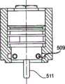
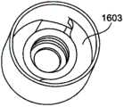
图1示出了一种涂覆剂装置,其可以是阀且被提供用于影响涂覆剂的排放。涂覆剂装置包括可插接的安装基座101,用于涂覆剂装置的可插接的安装。可插接的安装基座101例如连接到涂覆剂装置的壳体103。FIG. 1 shows a coating agent device, which may be a valve and is provided for influencing the discharge of coating agent. The coating agent device includes a
可插接的安装基座设有螺旋凹槽105,所述螺旋凹槽105包括用于接收固定鼻部的可选的固定凹槽107。而且,涂覆剂装置在排放端包括阀针109,所述阀针109至少部分被可插接的安装基座101环绕,且安装基座101的端面可设有用于密封环的凹槽111。The pluggable mounting base is provided with a
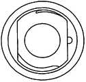
图2示出了相应的涂覆装置的壳体,所述壳体设有接收套筒201,所述接收套筒用于接收图1的涂覆剂装置的可插接的安装基座101。因此,在接收套筒201中,形成有凹槽203,所述凹槽203可包括弹簧圈205。弹簧圈205被提供用于接收图1所示的螺旋凹槽105。FIG. 2 shows the housing of a corresponding coating device, which housing is provided with a receiving
图3示出了弹簧圈,所述弹簧圈是弹性元件,且例如至少部分为圆弧形,而且可与弹簧圈205对应。弹簧圈在其内侧包括至少一个或两个非完整的固定鼻部301和具有组装和/或安装榫头303的转动固定结构,所述固定鼻部301接合在图1的固定凹槽107中。FIG. 3 shows a spring coil, which is an elastic element, and is, for example, at least partially arc-shaped, and may correspond to the
图4示出了图1的涂覆剂装置与图2的涂覆装置的连接。如图4中所示,弹簧圈205的弹性固定鼻部301接合在固定凹槽107中。FIG. 4 shows the connection of the coating agent device of FIG. 1 to the coating device of FIG. 2 . As shown in FIG. 4 , the
图1中所示的涂覆剂装置可具有一个或两个螺旋凹槽107。具有安装榫头303和一体形成的固定鼻部301的弹簧圈205插入图2的接收套筒中的凹槽203内,其中,安装榫头303在安装过程中接合在螺旋凹槽中。在这种情况下,可插接的安装基座101被引导到套筒201中,且例如转动65°,以实现转动固定的目的。为了拆卸涂覆剂装置,它被向回转动并拔出。从而,可使用直接拧紧元件。而且,可在弹簧圈205与壳体之间实现大的支承表面。而且,弹簧圈205可简单地更换。此外,涂覆装置的图2所示的壳体的构型是简单的。The coating agent device shown in FIG. 1 may have one or two
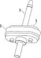
图5示出了一种涂覆剂装置,例如涂覆剂阀,其具有壳体501和可插接的安装基座503。在该可插接的安装基座503中,例如在阀基座中,在安装基座的一个横截面平面上横向嵌有两个保持销505和507。保持销505和507具有向外延伸的端部509,借此,形成了保持元件。而且,涂覆剂装置包括设置在排放端处的阀针511。在输入端设有控制输入口513,所述控制输入口用于例如借助于压缩空气致动阀针511。FIG. 5 shows a coating agent device, such as a coating agent valve, which has a
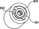
图6示出了涂覆装置、例如空气雾化器或颜色变换器的壳体,其具有用于接收图5的可插接的安装基座503的接收套筒601。接收套筒601包括轴向凹部603,保持元件509可在所述轴向凹部中被引导。而且,例如周向凹部605被提供用于转动固定目的。FIG. 6 shows a housing of a coating device, such as an air atomizer or a color changer, with a receiving
图7示出了处于安装状态的图5的涂覆剂装置。Fig. 7 shows the coating agent device of Fig. 5 in an installed state.
图8a和8b示出了具有轴向凹部603的接收套筒601的俯视图,所述轴向凹部603例如可由轴向凹槽形成。而且,在所述接收套筒中设有弹簧圈801,所述弹簧圈具有弯折臂,所述弯折臂设有保持凸头803。保持凸头803为了转动固定的目的而卡锁在轴向凹部603中,如图8b所示。为了安装图5的涂覆剂装置,其安装基座503插入接收套筒601中,且被转动例如90°,直到转动固定结构卡锁。当涂覆剂装置向回转动使得涂覆剂装置在转动90°之后可再次拔出时,它可以自动地解除卡锁。而且,在这种情况下,有利的是,通过卡锁转动固定结构,可视觉监测阀位置。Figures 8a and 8b show a top view of a receiving
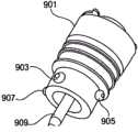
图9示出了涂覆剂装置,其具有壳体901和可插接的安装基座903,在所述安装基座903中,在不同的横截面上设有两个保持销905和907,所述保持销905和907例如被实施为标准销。涂覆剂装置还在排放端处包括阀针909。Figure 9 shows a coating agent device with a
保持销905和907具有作为保持元件向外延伸的端部。The retaining pins 905 and 907 have ends extending outward as retaining elements.
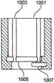
图10示出了涂覆装置的壳体,其具有接收套筒1001,四个轴向凹部1003、例如轴向凹槽设置在所述接收套筒1001中。而且,两个周向凹槽1005和1007被铣削出,且例如具有大约270°的角度的径向止挡。FIG. 10 shows the housing of the coating device, which has a receiving
图11示出了处于安装状态的图9的涂覆剂装置。为此,可插接的安装基座903被引导到套筒1001中,且例如转动90°直到止挡,从而转动固定结构被卡锁。为了拆卸涂覆剂装置,当涂覆剂装置向回转动90°使得涂覆剂装置可被拔出时,转动固定结构解除卡锁。在这种情况下,特别有利的是,转动固定止挡被确定,且阀位置的视觉检查可通过转动固定结构的卡锁实现。Figure 11 shows the coating agent device of Figure 9 in an installed state. To this end, the
图12示出了涂覆剂装置,其例如是涂覆剂阀,且具有壳体1201和可插接的安装基座1203,所述可插接的安装基座1203的壁在一个横截面平面上横向设有例如三个球销1205,所述球销1205可以被标准化。球销1205可以至少部分嵌在安装基座1203中,使得它们的凸出区段可形成用于转动固定目的的保持元件。Figure 12 shows a coating agent device, such as a coating agent valve, with a
图13示出了涂覆装置的壳体,其具有用于接收图12的安装基座1203的接收套筒1301。接收套筒1301设有多个、例如三个螺旋凹槽1305,所述螺旋凹槽1305的节距可分别为10%,其升程可为1mm。螺旋凹槽1305例如被铣削出。而且,球销1205也可被实施为销。此外,它们可被铣削为直接从阀壳体伸出的榫头。螺旋凹槽1305具有以下优点:它们可在简单的壳体构型中产生高的紧固力而可形成可靠连接。FIG. 13 shows the housing of the coating device with a receiving sleeve 1301 for receiving the mounting
图14示出了处于安装状态的图12的涂覆剂装置。为此,涂覆剂装置的安装基座1203被插入接收套筒1301中,并被例如转动60°,直到止挡。在这种情况下,转动固定通过针式密封件在摩擦锁定中的张力实施。为了拆卸涂覆剂装置,它向回转动且被拉出。Figure 14 shows the coating agent device of Figure 12 in an installed state. To this end, the mounting
图15示出了涂覆剂装置,例如阀,其具有阀壳体1501和可插接的安装基座1503,所述可插接的安装基座1503具有榫头区段1505,所述榫头区段1505可以以1.5mm的张紧节距、20°-例如180°铣削。Figure 15 shows a coating agent device, such as a valve, with a
图16示出了涂覆装置的壳体,其具有用于接收图15的安装基座1503的接收套筒1601。接收套筒1601设有例如延伸160°的保持凸缘1603。FIG. 16 shows the housing of the coating device with a receiving
图17a-17d示出了图15所示的安装基座1503在接收套筒1601中的连接。图17a示出了处于被插入但还未转动的状态的安装基座1503。图17b-17d示出了处于转动固定状态的连接。Figures 17a-17d illustrate the connection of the mounting
图18示出了涂覆剂装置,例如阀,其具有阀壳体1801和可插接的安装基座1803,所述可插接的安装基座1803部分设有螺纹1804,所述螺纹1804具有轴向平坦部分1805。平坦部分1805可以是被对称铣削的去除部,借此,安装基座根据“钥匙-锁孔”原理导入接收套筒中,且可在接收套筒中转动,以用于转动固定的目的。而且,安装基座1803设有在其导入接收套筒中的情况下用于定位的可选的定位销1806。Figure 18 shows a coating agent device, such as a valve, having a
图19示出了涂覆装置的壳体,其具有用于接收安装基座1803的接收套筒1901。接收套筒1901例如为细长形状,且包括用于接收安装基座的螺纹部分的侧向螺纹区段1903。而且,所述接收套筒可选地设有泄露孔1905。图19中示出的接收套筒1901具有用于接收螺纹1804的对称设置的螺纹凹部。然而,它们也可非对称地设置。FIG. 19 shows the housing of the coating device with a receiving
图19a、19b和19c示出了安装基座1803在接收套筒1901中的转动固定。图19b和19c示出了转动固定状态。19a, 19b and 19c illustrate the rotational fixation of the mounting
安装基座的螺纹1804可以是M14×1.5螺纹,所述螺纹例如可对称或非对称地在两侧被铣削掉一部分。相应地,接收套筒1901在两侧凹入。径向销1806可例如用于确定定位的目的,其中,在端面上,密封环可设置在凹槽1807中,以密封泄露。为了安装目的,安装基座1803被插入到接收套筒中,且例如转动近似90°-110°。在这种情况下,转动固定借助于针式密封件的摩擦锁定张紧作用实现。为了拆卸涂覆剂装置,所述涂覆剂装置向回转动并被拔出。The
图20a示出了涂覆剂装置,例如阀,其具有壳体2001和可插接的安装基座2003,所述安装基座2003具有非对称设置的轴向延伸的螺纹部分2005,所述螺纹部分2005由非对称的轴向铣削去除部2007分离开。而且,安装基座2003还包括泄露孔2009和用于密封环的凹槽2011。图中未示出可设置在安装基座2103的筒体中的阀针。Figure 20a shows a coating agent device, such as a valve, having a
图20b示出了相应的涂覆装置、例如雾化器或颜色变换器的壳体的型廓,该壳体具有非对称成型的接收套筒2002,所述接收套筒具有非对称设置的螺纹区段2004。FIG. 20b shows the profile of a housing of a corresponding application device, such as an atomizer or a color changer, which has an asymmetrically formed receiving
图23c-23e示出了处于安装状态的图20a的涂覆剂装置。图20c示出了插入状态,而图20d-20e清楚地示出了转动固定。Figures 23c-23e show the coating agent device of Figure 20a in an installed state. Figure 20c shows the inserted state, while Figures 20d-20e clearly show the rotational fixation.
螺纹2005可例如在两侧非对称地被铣削掉30°,其中,相应地,在接收套筒2002中可设有相同的螺纹且也在两侧凹入。安装基座2003在接收套筒2002中的确定定位可根据“钥匙-锁孔”原理借助于非对称表面实现。在这种情况下,转动固定通过针式密封件的摩擦锁定张紧作用实现。为了安装涂覆剂装置,它被例如转动近似75°,从而被转动固定。为了拆卸涂覆剂装置,它被向回转动并被拔出。在这种情况下,特别有利的是,定位可借助于楔形形状被使得可见,不再需要定位销。The
图21示出了涂覆剂装置2103的安装基座2101的截面。安装基座2101设有特殊的螺纹2105,所述螺纹的螺距可为1.5-3。螺纹的倾斜角度例如为30°,如图21所示。图21进一步示出了接收套筒2107的截面,所述接收套筒2107形成阀壳体。接收套筒包括设有相应的螺纹2109的壁。如图21进一步所示,螺纹2105、2109的倾斜角度可例如为30°。而且,螺纹沟槽和/或螺纹牙被圆角,这样,提高了对高应力的耐受性。螺纹2105、2109可进一步具有例如10,11,12或14mm的直径。螺纹2105或2109可为特殊的螺纹,例如具有圆角螺纹根和圆角螺纹顶的M11×3螺纹。FIG. 21 shows a cross section of the mounting
图1-21中示出的涂覆剂装置例如可以是自锁的和/或借助于形状锁定或摩擦锁定转动固定。而且,上述涂覆剂装置的各个特征可单独地或组合地使用,且可实现另外有利的实施例。The coating agent devices shown in FIGS. 1-21 can be self-locking and/or rotationally fixed by means of form-locking or friction-locking, for example. Furthermore, the individual features of the coating agent device described above can be used alone or in combination and further advantageous embodiments can be achieved.
图22示出了涂覆剂装置,例如涂覆剂阀,其具有驱动接口2201、设置在驱动接口的下游的壳体2203和阀针2205。该驱动接口2201具有大致卵形横截面,其中,向外弯曲的连接区域2207被提供,所述连接区域2207分别设有用于接收螺钉的孔2209。驱动接口2201还包括控制输入口2211,压缩空气可经由所述控制输入口2211被供给,以驱动涂覆剂装置的阀针2205。FIG. 22 shows a coating agent device, such as a coating agent valve, with a
图23示出了驱动接口2201的俯视图。图24示出了图22的涂覆剂装置的壳体2203的横截面。所述横截面为大致卵形,且呈驱动接口2201的横截面的形状。FIG. 23 shows a top view of
图25示出了图22的阀针2205,所述阀针2205设置在壳体2203中。阀针2205设置在活塞元件2501中,压缩空气可作用于所述活塞元件2501,这样,阀针2205可被驱动。活塞元件2501侧向包括环绕密封件2503,所述环绕密封件2503的横截面是类似于活塞元件2501的横截面的卵形,且呈壳体2203的横截面的形状。阀针2205与活塞元件一起设置在壳体2203的筒体中。FIG. 25 shows the
图26示出了多个涂覆剂装置的布置的俯视图,如图22所示。如图26所示,阀接口2201的细长结构使得涂覆剂装置可彼此邻近紧密设置,且可如图26所示地至少部分形状适配。这增大了涂覆剂装置在上述涂覆装置中的安装密度。FIG. 26 shows a top view of an arrangement of multiple coating agent devices, as shown in FIG. 22 . As shown in FIG. 26 , the elongated configuration of the
图27示出了图22的涂覆剂装置的图26所示的布置的侧视图。如图27所示,可例如为阀的涂覆剂装置可有利地由于驱动接口2201和壳体2203的横截面的细长形状而彼此紧邻地设置。FIG. 27 shows a side view of the arrangement shown in FIG. 26 of the coating agent device of FIG. 22 . As shown in FIG. 27 , the coating agent means, which may eg be valves, may advantageously be arranged next to each other due to the elongated shape of the cross-section of the
由于阀驱动装置的卵形结构,阀驱动装置可具有紧凑形状,其中,可增大可通到一个管道的能够彼此邻近设置的阀的数量。而且,与圆形活塞相比,由于使用卵形活塞或活塞部分而可期望得到增大的切换力。Owing to the oval shape of the valve drive, the valve drive can have a compact shape, wherein the number of valves which can lead to a line and which can be arranged next to each other can be increased. Also, an increased switching force can be expected due to the use of an oval piston or piston portion compared to a circular piston.
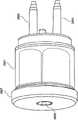
图28示出了涂覆剂装置,例如涂覆剂阀,其具有壳体2801和多个阀针2803和2805。涂覆剂装置包括驱动接口2807,所述驱动接口2807可具有用于驱动阀针2803的一个或多个控制输入口2809。这些阀针优选向外平行地设置,且可彼此单独地操作,使得阀针2803可例如用于用空气进行短暂吹扫,且阀针2805可用于用溶剂进行短暂冲洗。而且,阀针2803可被提供用于排放涂覆剂,阀针2805可被提供用于回送涂覆剂。驱动接口2807可例如如图26所示为卵形或为圆形或角形。FIG. 28 shows a coating agent device, such as a coating agent valve, having a
图29示出了图28的涂覆剂装置的前视图。如图29所示,每个阀针2803、2805均在与相应的针关联的相应的筒体或管道2901或2903中被引导。FIG. 29 shows a front view of the coating agent device of FIG. 28 . As shown in Figure 29, each
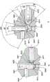
图30示出了图28的涂覆剂装置,所述涂覆剂装置连接到涂覆装置3001,例如雾化器或颜色变换器。涂覆剂装置3001包括两个阀座3003和3005,所述阀座分别被提供用于相应的阀针2803和/或2805。每个针2803或2805可在与其关联的筒体或管道3007或3009中移动,其中,辅助管道3011和3013与所述筒体或管道3007或3009垂直地设置。辅助管道3011和3013可例如被设置用于冲洗阀针2803和/或2805或者用于回送相应的涂覆剂。涂覆剂经由管道3007和3009被引导,从而会覆盖相应的针2803和/或2805。Figure 30 shows the coating agent device of Figure 28 connected to a coating device 3001, such as an atomizer or a color changer. The coating agent device 3001 comprises two valve seats 3003 and 3005, which are provided for
在上述双阀中,可实现至少两种独立的功能,这在较小的空间中可以实现。这种双阀例如在例如具有不同长度的针的所有可能的组合变型中可实施为功能阀、颜色变化器或雾化器,或被实施为具有两种功能的单阀组或被实施为具有多种功能的多阀组。这种阀可设置在一侧或相反地设置或沿一个圆设置,其中,致动动作可经由软管连接直接地实现或经由供给管孔间接地实现。阀还可与气动阀类似地串联设置。In the above-mentioned double valve, at least two independent functions can be realized, which can be realized in a small space. Such a double valve can be implemented, for example, in all possible combination variants, for example with needles of different lengths, as a functional valve, a color changer or an atomizer, or as a single valve group with two functions or as a Multi-valve group with multiple functions. Such valves can be arranged on one side or on the opposite side or along a circle, wherein the actuation action can be effected directly via a hose connection or indirectly via a supply tube bore. Valves can also be arranged in series similarly to pneumatic valves.
壳体2801和驱动接口2807可为圆形或卵形。而且,阀针2805和2803可设有卵形活塞元件2501,所述卵形活塞元件2501分别用密封件2503密封。
图31a-31d示出了上述类型的卵形活塞元件的视图。图32a-32c示出了卵形密封件的视图,所述卵形密封件可例如与卵形活塞元件相互作用。Figures 31a-31d show views of oval piston elements of the type described above. Figures 32a-32c show views of an oval seal which may, for example, interact with an oval piston element.
图33示出了具有阀针头3301和阀针轴3303的阀针,其可由塑料构成。阀针轴3303覆盖有护套3305,所述护套3305可由复合材料或陶瓷材料形成,使得护套3305比阀针轴3303更耐磨损。护套3305还可以由金属或DLC(类金刚石碳)形成。Figure 33 shows a valve needle with a valve needle head 3301 and a valve needle shaft 3303, which may consist of plastic. The needle shaft 3303 is covered with a sheath 3305 which may be formed from a composite or ceramic material such that the sheath 3305 is more wear resistant than the valve needle shaft 3303 . Sheath 3305 may also be formed of metal or DLC (diamond-like carbon).
阀针的背向阀针头3301的一端例如可以具有多个平坦面,例如可具有冲洗部分3307、密封部分3309和引导部分3311。冲洗部分3307用于改善对阀针的冲洗作用,例如对阀针的短暂的冲洗。冲洗部分3307例如以10°的倾斜角度细缩,或相对于阀针的纵向轴线以5°的角度细缩。在阀针的操作过程中与阀座相互作用且提供密封的密封部分3309设置在冲洗部分3307的紧邻下游。密封部分例如以30°的倾斜角度细缩,或相对于阀针的纵向轴线以15°的角度细缩。用于将阀针末端导入阀座中的引导部分3311设置在密封部分3309的下游。引导部分3311优选短于其他两个部分3307和3309,且以120°的倾斜角度细缩,和/或相对于上述纵向轴线以60°的角度细缩。护套3305和部分3307-3311均是可选的。The end of the valve needle facing away from the valve needle head 3301 may have, for example, a plurality of flat surfaces, such as a flushing portion 3307 , a sealing portion 3309 and a guiding portion 3311 . The flushing portion 3307 is used to improve flushing of the valve needle, for example, a brief flushing of the valve needle. The flushing portion 3307 tapers, for example, at an angle of inclination of 10°, or at an angle of 5° relative to the longitudinal axis of the valve needle. A sealing portion 3309 that interacts with the valve seat and provides a seal during operation of the valve needle is provided immediately downstream of the flushing portion 3307 . The sealing portion tapers, for example, at an inclination angle of 30°, or at an angle of 15° relative to the longitudinal axis of the valve needle. A guide portion 3311 for guiding the needle tip into the valve seat is provided downstream of the sealing portion 3309 . The guide portion 3311 is preferably shorter than the other two portions 3307 and 3309 and tapers at an angle of inclination of 120°, and/or at an angle of 60° relative to the aforementioned longitudinal axis. Sheath 3305 and sections 3307-3311 are optional.
图34a示出了涂覆剂装置的第一阀针3401,所述第一阀针3401设置在涂覆装置的筒体和/或管道3403中。筒体3403包括阀座3405,所述阀座3405借助于阀针3401的密封部分3407密封。密封部分3407例如与密封部分3307对应。阀针3401还包括引导部分3409和冲洗部分3411,所述引导部分3409可与引导部分3311对应,所述冲洗部分3411可与冲洗部分3307对应。如图34a所示,中间冲洗空间可通过使冲洗部分3411细缩而得到扩大。Fig. 34a shows a
涂覆剂装置还可具有第二针3413,所述第二针3413设置在与阀针3401垂直的管道3415中。第二阀针同样可具有冲洗部分3417、密封部分3419和引导部分3421,其中,部分3417、3419和3421可具有部分3307、3309和3311的特征。第二阀针3413可例如被操作,以冲洗第一阀针3401。涂覆剂装置还包括辅助管道3425,所述辅助管道3425通到涂覆剂管道3403中。The coating agent device may also have a
图34b示出了当移出阀座时的第一阀针3401的引导部分3409、密封部分3407和冲洗部分3411的倾斜角度。如图34b所示,阀座包括与密封部分3407对应的密封部分3425。Figure 34b shows the inclination angles of the
图34b还示出了当移出阀座时的第二阀针3413。阀座例如可具有密封部分3427,所述密封部分3427例如以90°的倾斜角度倾斜。该阀座也可具有另一细缩部分3429,所述另一细缩部分3429以例如90°的角度细缩,且被提供用于扩大阀座与第二阀针3413的冲洗部分3417之间的空隙。Figure 34b also shows the
图35示出了多次倾斜的涂覆剂阀3501,所述涂覆剂阀3501当处于闭合状态时位于涂覆剂装置3505、例如雾化器或颜色变换器的阀座3503中。阀针3501包括引导部分3507、密封部分3509和冲洗部分3511,它们可具有图33所示的部分的特征。如图35所示,优选仅密封部分3509以密封方式与阀座3503相互作用,其中,引导部分3507和冲洗部分3511均不与阀座接触。阀针3501设置在筒体和/或管道3513中,其中,由于提供了倾斜的冲洗部分3511,因此较大的空隙被提供用于冲洗针3501。为此,涂覆剂装置3505可具有辅助管道3515。Figure 35 shows a multi-tilt
图36示出了处于打开状态的图35的阀针。密封部分3509可相对于纵向轴线3601以密封角度3603细缩,所述密封角度3603例如可为15°。阀座3503优选包括密封部分3605,所述密封部分3605同样以相同的密封角度3603细缩。Figure 36 shows the valve needle of Figure 35 in an open state. The sealing
图37示出了具有引导部分3701、密封部分3703和冲洗部分3705的阀针末端。引导部分3701相对于纵向轴线3707以引导角度3709细缩,所述引导角度可为60°。密封部分3703相对于纵向轴线3707以密封角度3711细缩,所述密封角度可以为15°。冲洗部分3705相对于纵向轴线3707以冲洗角度3713细缩,所述冲洗角度可为5°。FIG. 37 shows a valve needle tip with a
阀针末端例如可由塑料形成,且可与硬质阀座相互作用,所述阀座例如由不锈钢形成。阀座中的密封结构可例如实施成不具有座套,其中,特别是在针座位于柔软材料与硬质材料之间的过渡部分中的情况下,与技术处理过程相关的可靠密封结构可得以实现。根据本发明,接合面得到相当大地扩大,这样,泄露危险可降低。最后,阀针的耐磨表面可在针的面向阀驱动装置的密封结构的区域中实现。The needle tip may be formed, for example, from plastic, and may interact with a hard valve seat, such as formed from stainless steel. The seal in the valve seat can be embodied, for example, without a seat sleeve, wherein, especially in the case of the needle seat in the transition between the soft material and the hard material, a reliable seal in relation to the technical process can be achieved. accomplish. According to the invention, the joint surfaces are enlarged considerably, so that the risk of leakage can be reduced. Finally, a wear-resistant surface of the valve needle can be realized in the region of the needle facing the sealing structure of the valve drive.
相应的涂覆剂装置的壳体中的阀座例如通过两个倾斜台阶构造,与阀针的三次倾斜末端不同。密封部分优选在两侧具有相同的角度。The valve seat in the housing of the respective coating agent device is configured, for example, by two inclined steps, as opposed to the three-times inclined end of the valve needle. The sealing portion preferably has the same angle on both sides.
上述涂覆剂装置可以是阀,在喷漆技术中,所述阀可用作针阀和/或座阀、功能阀、颜色变换器阀、雾化器阀或主针阀。涂覆装置可以是在喷漆技术中使用的任何装置、例如雾化器或颜色变换器,所述涂覆装置可与这种涂覆剂装置相互作用。The aforementioned coating agent device can be a valve which, in painting technology, can be used as needle valve and/or seat valve, function valve, color changer valve, atomizer valve or main needle valve. The application device can be any device used in painting technology, such as an atomizer or a color changer, which can interact with such a coating agent device.
Claims (39)
Priority Applications (2)
| Application Number | Priority Date | Filing Date | Title |
|---|---|---|---|
| CN201611052137.7ACN107084263A (en) | 2009-05-06 | 2010-05-05 | Coating agent device and coating unit |
| CN201611052136.2ACN107763029A (en) | 2009-05-06 | 2010-05-05 | Coating agent device and coating unit |
Applications Claiming Priority (3)
| Application Number | Priority Date | Filing Date | Title |
|---|---|---|---|
| DE102009020077ADE102009020077A1 (en) | 2009-05-06 | 2009-05-06 | Coating agent device and coating device |
| DE102009020077.0 | 2009-05-06 | ||
| PCT/EP2010/002760WO2010127847A2 (en) | 2009-05-06 | 2010-05-05 | Coating agent device and coating device |
Related Child Applications (2)
| Application Number | Title | Priority Date | Filing Date |
|---|---|---|---|
| CN201611052136.2ADivisionCN107763029A (en) | 2009-05-06 | 2010-05-05 | Coating agent device and coating unit |
| CN201611052137.7ADivisionCN107084263A (en) | 2009-05-06 | 2010-05-05 | Coating agent device and coating unit |
Publications (2)
| Publication Number | Publication Date |
|---|---|
| CN102803754Atrue CN102803754A (en) | 2012-11-28 |
| CN102803754B CN102803754B (en) | 2017-03-01 |
Family
ID=42338330
Family Applications (3)
| Application Number | Title | Priority Date | Filing Date |
|---|---|---|---|
| CN201611052136.2APendingCN107763029A (en) | 2009-05-06 | 2010-05-05 | Coating agent device and coating unit |
| CN201611052137.7APendingCN107084263A (en) | 2009-05-06 | 2010-05-05 | Coating agent device and coating unit |
| CN201080025153.1AActiveCN102803754B (en) | 2009-05-06 | 2010-05-05 | Coating agent device and coating device |
Family Applications Before (2)
| Application Number | Title | Priority Date | Filing Date |
|---|---|---|---|
| CN201611052136.2APendingCN107763029A (en) | 2009-05-06 | 2010-05-05 | Coating agent device and coating unit |
| CN201611052137.7APendingCN107084263A (en) | 2009-05-06 | 2010-05-05 | Coating agent device and coating unit |
Country Status (13)
| Country | Link |
|---|---|
| US (5) | US9528539B2 (en) |
| EP (3) | EP3133300B1 (en) |
| JP (3) | JP2012525961A (en) |
| KR (1) | KR101874332B1 (en) |
| CN (3) | CN107763029A (en) |
| DE (1) | DE102009020077A1 (en) |
| ES (3) | ES2925555T3 (en) |
| HU (3) | HUE031787T2 (en) |
| MX (3) | MX2011011778A (en) |
| PL (2) | PL3133301T3 (en) |
| PT (1) | PT3133301T (en) |
| RU (3) | RU2683826C2 (en) |
| WO (1) | WO2010127847A2 (en) |
Cited By (4)
| Publication number | Priority date | Publication date | Assignee | Title |
|---|---|---|---|---|
| CN108837976A (en)* | 2018-04-27 | 2018-11-20 | 温州大学激光与光电智能制造研究院 | Paint automatic detection device |
| CN110270476A (en)* | 2019-07-04 | 2019-09-24 | 华霆(合肥)动力技术有限公司 | A kind of spot gluing equipment |
| CN110325722A (en)* | 2017-11-23 | 2019-10-11 | 埃贝斯佩歇排气技术有限责任两合公司 | Butterfly valve |
| WO2022105387A1 (en)* | 2020-11-23 | 2022-05-27 | 石家庄禾柏生物技术股份有限公司 | Nozzle for kit |
Families Citing this family (11)
| Publication number | Priority date | Publication date | Assignee | Title |
|---|---|---|---|---|
| KR101302958B1 (en)* | 2013-07-09 | 2013-09-10 | 윤종복 | Fuel jet pump which has structural improvement of sub housing |
| KR200480920Y1 (en)* | 2014-12-19 | 2016-07-22 | 김성곤 | Tool for releasing injector, and injection tool unit |
| FR3034962B1 (en)* | 2015-04-14 | 2019-06-14 | Thierry CAI | DEVICE FOR ASSEMBLING A BATTERY ELEMENT WITH THE USE TIP OF AN ELECTRONIC CIGARETTE TO WHICH IT IS ASSOCIATED |
| CN110139690A (en)* | 2016-11-08 | 2019-08-16 | 医疗品牌研究有限公司 | Applicator device |
| WO2018109905A1 (en)* | 2016-12-15 | 2018-06-21 | 株式会社イワキ | Reciprocating pump |
| JP6606807B2 (en)* | 2017-03-08 | 2019-11-20 | Smc株式会社 | Shaft coupling structure and fluid pressure device |
| CN107806525A (en)* | 2017-11-29 | 2018-03-16 | 嘉孚朗机器人设备(苏州)有限公司 | AB glue circulates valve body |
| CN109786088B (en)* | 2019-04-01 | 2024-10-15 | 江苏神马电力股份有限公司 | Transformer bushing's conducting rod end assembly spare and transformer bushing |
| CN114833030B (en)* | 2022-03-29 | 2023-07-14 | 烽禾升医疗设备(昆山)有限公司 | Automatic glue filling mechanism |
| CN115041359B (en)* | 2022-06-02 | 2023-10-13 | 洛阳市锐创电气设备有限公司 | Ceramic on-off valve for numerical control sealing dispensing machine |
| DE102024101667A1 (en)* | 2024-01-22 | 2025-08-07 | Dürr Systems Ag | Application system component with a thread for connection to a thread of an application system device |
Citations (5)
| Publication number | Priority date | Publication date | Assignee | Title |
|---|---|---|---|---|
| US2296079A (en)* | 1939-01-23 | 1942-09-15 | Gen Mills Inc | Gluing head |
| US4953756A (en)* | 1987-06-03 | 1990-09-04 | Loctite Corporation | Modular dispensing system |
| EP0642842A2 (en)* | 1993-09-13 | 1995-03-15 | Illinois Tool Works Inc. | Nozzle assembly |
| DE19516697A1 (en)* | 1995-05-06 | 1996-11-07 | Ford Werke Ag | Device for applying pasty media |
| EP1157747A2 (en)* | 2000-05-24 | 2001-11-28 | Illinois Tool Works, Inc. | Removable inline nozzle filter |
Family Cites Families (126)
| Publication number | Priority date | Publication date | Assignee | Title |
|---|---|---|---|---|
| DE492394C (en) | 1925-12-16 | 1930-02-21 | Prea Helmbrecht & Knoellner G | Spray painting system |
| US3109672A (en) | 1960-02-15 | 1963-11-05 | United States Steel Corp | Threaded tubing joint |
| US3201048A (en)* | 1963-04-19 | 1965-08-17 | Gen Motors Corp | Multiple fluid spray gun with remotely operable selective valve control |
| US3323402A (en) | 1965-10-08 | 1967-06-06 | Standard Pressed Steel Co | Thread forms |
| US3690518A (en)* | 1970-11-13 | 1972-09-12 | Nordson Corp | Modular applicator system |
| GB1300352A (en) | 1971-04-20 | 1972-12-20 | Shell Int Research | Apparatus for spraying a material |
| US3922009A (en) | 1974-07-05 | 1975-11-25 | Byron Jackson Inc | Coupling |
| US4171012A (en) | 1975-11-25 | 1979-10-16 | Holmes Horace D | Locking thread construction |
| JPS5842040Y2 (en)* | 1976-08-25 | 1983-09-22 | トヨタ自動車株式会社 | spray gun |
| US4163523A (en)* | 1976-12-15 | 1979-08-07 | Vincent Raymond A | Multicolor paint dispensing system having a pressure responsive color change valve |
| JPS582444Y2 (en)* | 1976-12-27 | 1983-01-17 | 新日本製鐵株式会社 | Spray gun for marking |
| JPS5541824A (en) | 1978-09-19 | 1980-03-24 | Babcock Hitachi Kk | Detecting device for height of fluidized layer |
| US4432682A (en) | 1978-12-04 | 1984-02-21 | Microdot Inc. | Threaded fastener assembly |
| US4341497A (en) | 1980-04-02 | 1982-07-27 | Microdot Inc. | Prevailing torque bolt |
| JPS6051867B2 (en)* | 1980-08-04 | 1985-11-15 | 日本ランズバ−グ株式会社 | How to change paint color |
| US4594039A (en) | 1981-05-11 | 1986-06-10 | Microdot Inc. | Fastener |
| CS227613B1 (en)* | 1982-02-03 | 1984-04-16 | Vaclav Dohnal | Boyonet joint,especially for coupling a body with armature yoke |
| US4453647A (en)* | 1983-01-26 | 1984-06-12 | Neat Benjamin C | Plastic container having threaded closure |
| US4549754A (en) | 1983-06-20 | 1985-10-29 | Reed Tubular Products Company | Tool joint |
| SU1166838A1 (en) | 1983-11-03 | 1985-07-15 | Stukhlyak Petr D | Apparatus for applying the coatings |
| JPS616488A (en) | 1984-06-20 | 1986-01-13 | 日本鋼管株式会社 | Threaded joints for oil country pipes |
| IT1176371B (en) | 1984-06-29 | 1987-08-18 | Innocenti Santeustacchio Spa | JOINT FOR HEAD-TO-HEAD CONNECTION OF METAL TUBES, IN PARTICULAR FOR MARINE PALLING |
| DE3512967A1 (en)* | 1985-04-11 | 1986-10-16 | Hilti Ag, Schaan | Motor-driven hand spray unit for processing plastic compositions |
| US4896834A (en) | 1984-08-30 | 1990-01-30 | The Devilbiss Company | Rotary atomizer apparatus |
| JPS61236914A (en) | 1985-02-15 | 1986-10-22 | ジヨ−ジ シ−ブルツク ウイング | Screw fastener and combination of screw fastener |
| US4988127A (en) | 1985-04-24 | 1991-01-29 | Cartensen Kenneth J | Threaded tubing and casing joint |
| SU1466803A1 (en) | 1986-02-18 | 1989-03-23 | Всесоюзный Проектно-Технологический Институт По Электробытовым Машинам И Приборам | Hanger for articles |
| US4943178A (en) | 1986-05-08 | 1990-07-24 | Illinois Tool Works, Inc. | Mounting structure for rotating bodies |
| GB2190606B (en) | 1986-05-19 | 1990-02-14 | Graco Inc | A rotary spray atomizer |
| IT1199343B (en) | 1986-12-23 | 1988-12-30 | Dalmine Spa | PERFECTED JOINT FOR WELL COATING PIPES |
| JPS63167235A (en) | 1986-12-27 | 1988-07-11 | Saginomiya Seisakusho Inc | Car drive system load test equipment |
| US4810149A (en) | 1987-09-17 | 1989-03-07 | Lee Jae B | Screw-type fastening device |
| JPH0174134U (en) | 1987-11-05 | 1989-05-19 | ||
| DE3744587A1 (en) | 1987-12-31 | 1989-07-13 | Dittberner Gmbh Klebstoff Auft | METHOD FOR APPLYING GLUE TO ENDLESS THREADS AND CORRESPONDING DEVICE |
| JPH028666A (en) | 1988-06-24 | 1990-01-12 | Furukawa Electric Co Ltd:The | refrigerant distributor |
| US4846226A (en)* | 1988-08-11 | 1989-07-11 | Binks Manufacturing Company | Color changer |
| JPH0286666A (en) | 1988-09-22 | 1990-03-27 | Mitsubishi Heavy Ind Ltd | Magnetic powder for printing |
| JPH0543339Y2 (en)* | 1988-12-15 | 1993-11-01 | ||
| JPH0286666U (en)* | 1988-12-24 | 1990-07-09 | ||
| DE3912700C1 (en) | 1989-04-18 | 1990-10-11 | Ransburg-Gema Gmbh, 6056 Heusenstamm, De | Rotary spray coater - has atomiser ring with solvent channels, and includes annular air inlets |
| US5127784A (en)* | 1989-04-19 | 1992-07-07 | Halliburton Company | Fatigue-resistant buttress thread |
| MA21865A1 (en) | 1989-06-09 | 1990-12-31 | Galva Lorraine | METHOD, ENCLOSURE AND INSTALLATION FOR CONTINUOUS / INTERMITTENT COATING OF OBJECTS BY PASSING THESE OBJECTS THROUGH A LIQUID MASS OF A COATING PRODUCT. |
| DE3925931A1 (en)* | 1989-08-04 | 1991-02-07 | Devilbiss Gmbh | SPRAY GUN |
| EP0455371A3 (en) | 1990-04-24 | 1992-04-22 | Engineering Incorporated | Robotic carrier mechanism for aircraft maintenance |
| US5146950A (en)* | 1990-07-11 | 1992-09-15 | Ransburg Corporation | Modular plastic color changer |
| CN2086341U (en)* | 1990-10-20 | 1991-10-09 | 张誉燮 | Fast fixture device for screw bolt, nut |
| JP2704681B2 (en)* | 1991-04-30 | 1998-01-26 | トリニティ工業株式会社 | Color change cleaning method for multicolor coating equipment |
| JPH04127409U (en) | 1991-05-13 | 1992-11-19 | 株式会社京浜精機製作所 | coupling device |
| JPH057354U (en) | 1991-07-05 | 1993-02-02 | ランズバーグ・オートモーテイブ株式会社 | Spray gun for painting |
| JP3294613B2 (en) | 1992-03-03 | 2002-06-24 | ティーティーピー グループ ピーエルシー | Electrical marking device |
| US5462315A (en) | 1992-03-09 | 1995-10-31 | Marubeni Tubulars, Inc. | Stabilized center-shoulder-sealed tubular connection |
| CN2123647U (en)* | 1992-04-30 | 1992-12-02 | 叶中午 | Quick assemble-disassemble combined and adjustable nut |
| CA2097091C (en) | 1992-07-10 | 2000-10-31 | Sidney A. Taylor | High pressure water jet cleaner and coating applicator |
| FR2698564B1 (en) | 1992-12-01 | 1995-03-03 | Sames Sa | Device for spraying a coating product with a rotary spraying element and tool for mounting and dismounting such a rotary element. |
| GB9301369D0 (en)* | 1993-01-25 | 1993-03-17 | Lurmark Ltd | Bayonet fitting for spray nozzle holder |
| JP3256632B2 (en) | 1994-06-27 | 2002-02-12 | アネスト岩田株式会社 | 2-pack polyester automatic gun |
| JP2598767B2 (en) | 1994-12-27 | 1997-04-09 | エービービー・インダストリー株式会社 | Spray gun for painting |
| DE19516967A1 (en)* | 1995-05-12 | 1996-11-14 | Basf Ag | Process for the preparation of polymers of vinylic monomers with a narrow molecular weight distribution by controlled radical polymerization |
| DE19521755C1 (en) | 1995-06-14 | 1996-10-02 | Schunk Fritz Gmbh | System repeatedly connecting two components |
| JPH09112522A (en) | 1995-10-12 | 1997-05-02 | Pop Rivet Fastener Kk | Dump bolt |
| JPH09217668A (en) | 1996-02-09 | 1997-08-19 | Isuzu Ceramics Kenkyusho:Kk | Fuel injection nozzle for low viscous oil |
| JP3629814B2 (en)* | 1996-05-24 | 2005-03-16 | 株式会社スリーボンド | Material discharge device and seal body used therefor |
| JP3056080B2 (en) | 1996-07-31 | 2000-06-26 | 埼玉日本電気株式会社 | Mobile phone |
| US5730370A (en) | 1996-11-14 | 1998-03-24 | Bex Engineering Ltd. | Leak resistant nozzle ball |
| JP3038884U (en) | 1996-12-19 | 1997-06-30 | 台生企業股▲ふん▼有限公司 | Needle-shaped stationery with different width areas |
| JP3433056B2 (en) | 1997-07-10 | 2003-08-04 | Abb株式会社 | Rotary atomizing head type coating equipment |
| JP3977496B2 (en) | 1997-10-15 | 2007-09-19 | 株式会社スズキ螺子製作所 | Male thread, and screwed structure of male thread and female thread |
| CN2325579Y (en)* | 1998-01-16 | 1999-06-23 | 崔书军 | Quick fastened screw bolt and nut |
| US6220843B1 (en)* | 1998-03-13 | 2001-04-24 | Nordson Corporation | Segmented die for applying hot melt adhesives or other polymer melts |
| RU2157736C2 (en)* | 1998-04-17 | 2000-10-20 | Всероссийский научно-исследовательский и проектно-технологический институт по использованию техники и нефтепродуктов в сельском хозяйстве | Device for application of anticorrosive mastic |
| JP3056080U (en) | 1998-07-22 | 1999-02-02 | 太陽鉄工株式会社 | Cylinder with stroke adjustment mechanism |
| DE19914343A1 (en)* | 1999-03-30 | 2000-10-05 | Miroslaw Muche | Method for application of heated liquid or paste sealant to container closures uses nozzle head with sealant feed and return pipes for constant sealant flow, and throttle unit |
| DE19958569C1 (en) | 1999-12-04 | 2001-02-15 | Sata Farbspritztechnik | Paint spray gun with threaded body and ring, thread of which is trapezoid |
| ITTV20010008A1 (en) | 2001-01-17 | 2002-07-17 | Hip Srl High Ind Performance S | SPLMING HEAD PARTICULARLY FOR THERMOPLASTIC MATERIAL |
| JP2002225495A (en)* | 2001-01-19 | 2002-08-14 | Kan-Fu Yu | Simple applicator |
| FR2819876B1 (en)* | 2001-01-19 | 2003-02-28 | Eisenmann France Sarl | TINT CHANGER BLOCK MODULE FOR PAINT INSTALLATION |
| US6619563B2 (en)* | 2001-05-14 | 2003-09-16 | Efc Systems, Inc. | Manifold block for flow control in coating applications |
| EP1396287A1 (en) | 2001-06-08 | 2004-03-10 | Uegaki, Tateo | Painting device |
| JP4205380B2 (en) | 2001-08-09 | 2009-01-07 | Abb株式会社 | Cartridge type coating equipment |
| US20030234299A1 (en) | 2001-08-09 | 2003-12-25 | Toshio Hosoda | Cartridge type coater |
| US6669057B2 (en) | 2001-10-31 | 2003-12-30 | Nordson Corporation | High-speed liquid dispensing modules |
| JP2003211036A (en) | 2002-01-17 | 2003-07-29 | Asahi Sunac Corp | Painting equipment |
| ITRM20020234A1 (en) | 2002-04-30 | 2003-10-30 | Tenaris Connections Bv | THREADED JOINT FOR PIPES. |
| ITRM20020274A1 (en) | 2002-05-16 | 2003-11-17 | Tenaris Connections Bv | THREADED JOINT FOR PIPES. |
| US6682001B2 (en)* | 2002-06-19 | 2004-01-27 | Illinois Tool Works Inc. | Modular color changer |
| DE10238055B4 (en) | 2002-08-20 | 2004-10-28 | Ejot Gmbh & Co. Kg | Screw with self-locking thread |
| ITRM20020453A1 (en) | 2002-09-10 | 2004-03-11 | Sipa Spa | CONTAINER PAINTING PROCESS AND PLANT. |
| ITRM20030065A1 (en) | 2003-02-13 | 2004-08-14 | Tenaris Connections Bv | THREADED JOINT FOR PIPES. |
| US6854617B2 (en)* | 2003-03-21 | 2005-02-15 | Rieke Corporation | Blow-molded paint container |
| CN2612830Y (en)* | 2003-04-11 | 2004-04-21 | 马家贵 | Easy-mounting and easy-removing bolt and nut fastener |
| US7249696B2 (en)* | 2003-05-22 | 2007-07-31 | Industrias Penalver, S.L. | Pneumatic liquid-dispensing gun |
| ES2258248T3 (en)* | 2003-07-28 | 2006-08-16 | Durr Systems Gmbh | PROVISION OF COLOR CHANGE VALVES OF A COATING INSTALLATION. |
| FR2863681B1 (en) | 2003-12-11 | 2006-02-24 | Vallourec Mannesmann Oil & Gas | FATIGUE-RESISTANT THREADED TUBULAR JOINT |
| CN2672355Y (en) | 2004-01-08 | 2005-01-19 | 张永华 | Full screwthread locking nut |
| US7455329B2 (en) | 2004-01-29 | 2008-11-25 | Grant Prideco, L.P. | Fast make-up fatigue resistant rotary shouldered connection |
| ATE390207T1 (en) | 2004-02-06 | 2008-04-15 | Sames Technologies | SPRAY BELL FOR A ROTARY ATOMIZER WITH MAGNETIC MOUNTING |
| US7520410B2 (en)* | 2004-03-01 | 2009-04-21 | Masterchem Industries, Llc | Container sealing system |
| US7694855B2 (en) | 2004-04-23 | 2010-04-13 | Nordson Corporation | Dispenser having a pivoting actuator assembly |
| JP4520771B2 (en) | 2004-05-27 | 2010-08-11 | 株式会社スズキ螺子製作所 | Tapping screw to prevent loosening |
| DE102004032045A1 (en) | 2004-07-02 | 2006-01-26 | J. Wagner Ag | Rotary atomizer for atomizing liquid and powdered media, especially paints, lacquers and similar materials comprises a housing and a bell having regions made from plastic or aluminum |
| JP4600808B2 (en)* | 2004-07-16 | 2010-12-22 | Smc株式会社 | Paint selector valve |
| ATE482341T1 (en)* | 2004-11-03 | 2010-10-15 | Wabco Gmbh | THREAD FOR A SCREW CONNECTION |
| DE102005020623A1 (en) | 2004-12-21 | 2006-06-22 | Dürr Systems GmbH | Rotary atomizer for use with coating machine, has centering ring with two external threads, in which one abuts against internal thread of drive motor shaft when bell-shaped plate unscrews from another internal thread while operating plate |
| CN2835682Y (en)* | 2005-07-01 | 2006-11-08 | 陈慧愿 | Quick-to-mount joint |
| US7549682B2 (en) | 2005-09-19 | 2009-06-23 | Vetco Gray Inc. | Threaded pipe connector |
| US8864049B2 (en)* | 2005-10-21 | 2014-10-21 | Durr Systems Gmbh | Rotary atomizer with a spraying body |
| US7654472B2 (en) | 2005-10-21 | 2010-02-02 | Durr Systems, Inc. | Rotary atomizer with a spraying body |
| JP4885529B2 (en) | 2005-12-08 | 2012-02-29 | 住友重機械工業株式会社 | Radiation detection unit and radiation inspection apparatus |
| CN100462606C (en)* | 2006-03-22 | 2009-02-18 | 王罗平 | Air-valve joint of air-inflating device with automatic switchover selection connection mouth |
| US20070280803A1 (en) | 2006-06-02 | 2007-12-06 | Alan Pritchard | All-metal thread locking/prevailing torque threaded fastener |
| DE202006010422U1 (en)* | 2006-07-06 | 2006-08-31 | Evertz Hydrotechnik Gmbh & Co.Kg | pray device for cold and hot rolling equipment has several spray valves detachably fixed by quick release fasteners |
| RU59450U1 (en) | 2006-08-21 | 2006-12-27 | Андрей Николаевич Куземский | DEVICE FOR APPLICATION OF DYEING, ADHESIVE LIQUIDS AND SOLUTIONS (OPTIONS) |
| JP5059377B2 (en) | 2006-11-08 | 2012-10-24 | 株式会社ニレコ | Marking nozzle device |
| WO2008060935A2 (en)* | 2006-11-15 | 2008-05-22 | Nordson Corporation | Liquid dispensing apparatus |
| US8061564B2 (en)* | 2006-11-15 | 2011-11-22 | Nordson Corporation | Liquid dispensing apparatus including an attachment member |
| JP4874078B2 (en) | 2006-12-12 | 2012-02-08 | 株式会社ケイ・ジー・ケイ | Sealer discharge device |
| JP2008208983A (en) | 2007-02-23 | 2008-09-11 | World Lock:Kk | Slack preventing structure for screw with nut having inclined screw bottom portion |
| JP4941058B2 (en) | 2007-04-02 | 2012-05-30 | 住友金属工業株式会社 | Threaded joints for steel pipes |
| ES2525817T3 (en) | 2007-08-13 | 2014-12-30 | Research Engineering&Amp;Manufacturing, Inc. | Fixing element that forms a thread |
| US7959034B2 (en)* | 2007-08-17 | 2011-06-14 | The Dial Corporation | Liquid product pouring and measuring package with drain-back spout fitment and tight-sealing measuring cup assembly |
| US7731466B2 (en) | 2007-11-02 | 2010-06-08 | Gm Global Technology Operations, Inc. | Thread profile modification for controlled stiffness |
| CN201227179Y (en)* | 2008-07-15 | 2009-04-29 | 浙江沁园水处理科技股份有限公司 | Double-channel type Y shaped water tap |
| DE102008038760B4 (en) | 2008-08-12 | 2010-06-24 | Abb Ag | processing concept |
| PL2427277T3 (en) | 2009-05-06 | 2017-04-28 | Dürr Systems Ag | Coating system component comprising at least one holding part |
| DE102010013414A1 (en) | 2010-03-30 | 2011-10-06 | Dürr Systems GmbH | Coating system component for painting system to coat e.g. motor vehicle body, has holding part arranged on fastening base for detachable connection with coating system device, where holding part is external thread with special configuration |
| JP6131445B2 (en) | 2015-04-27 | 2017-05-24 | 有限会社ピエデック技術研究所 | Piezoelectric vibrator and piezoelectric unit |
- 2009
- 2009-05-06DEDE102009020077Apatent/DE102009020077A1/enactivePending
- 2010
- 2010-05-05ESES16002115Tpatent/ES2925555T3/enactiveActive
- 2010-05-05HUHUE10720270Apatent/HUE031787T2/enunknown
- 2010-05-05RURU2015115887Apatent/RU2683826C2/enactive
- 2010-05-05MXMX2011011778Apatent/MX2011011778A/enactiveIP Right Grant
- 2010-05-05MXMX2015014548Apatent/MX349883B/enunknown
- 2010-05-05RURU2011149479/12Apatent/RU2553033C2/enactive
- 2010-05-05MXMX2015014546Apatent/MX346938B/enunknown
- 2010-05-05JPJP2012508946Apatent/JP2012525961A/enactivePending
- 2010-05-05PLPL16002116Tpatent/PL3133301T3/enunknown
- 2010-05-05HUHUE16002116Apatent/HUE051532T2/enunknown
- 2010-05-05EPEP16002115.0Apatent/EP3133300B1/enactiveActive
- 2010-05-05ESES16002116Tpatent/ES2812886T3/enactiveActive
- 2010-05-05PLPL10720270Tpatent/PL2427663T3/enunknown
- 2010-05-05CNCN201611052136.2Apatent/CN107763029A/enactivePending
- 2010-05-05RURU2015115938Apatent/RU2678034C2/enactive
- 2010-05-05EPEP16002116.8Apatent/EP3133301B1/enactiveActive
- 2010-05-05HUHUE16002115Apatent/HUE059782T2/enunknown
- 2010-05-05ESES10720270.7Tpatent/ES2614941T3/enactiveActive
- 2010-05-05WOPCT/EP2010/002760patent/WO2010127847A2/enactiveApplication Filing
- 2010-05-05USUS13/319,241patent/US9528539B2/enactiveActive
- 2010-05-05CNCN201611052137.7Apatent/CN107084263A/enactivePending
- 2010-05-05KRKR1020117028916Apatent/KR101874332B1/enactiveActive
- 2010-05-05PTPT160021168Tpatent/PT3133301T/enunknown
- 2010-05-05EPEP10720270.7Apatent/EP2427663B1/enactiveActive
- 2010-05-05CNCN201080025153.1Apatent/CN102803754B/enactiveActive
- 2015
- 2015-08-07JPJP2015156717Apatent/JP6145138B2/enactiveActive
- 2015-08-07JPJP2015156716Apatent/JP6338556B2/enactiveActive
- 2016
- 2016-09-28USUS15/278,553patent/US10047781B2/enactiveActive
- 2016-11-15USUS15/351,583patent/US9839933B2/enactiveActive
- 2017
- 2017-11-10USUS15/808,987patent/US10605291B2/enactiveActive
- 2017-11-10USUS15/809,000patent/US10605292B2/enactiveActive
Patent Citations (5)
| Publication number | Priority date | Publication date | Assignee | Title |
|---|---|---|---|---|
| US2296079A (en)* | 1939-01-23 | 1942-09-15 | Gen Mills Inc | Gluing head |
| US4953756A (en)* | 1987-06-03 | 1990-09-04 | Loctite Corporation | Modular dispensing system |
| EP0642842A2 (en)* | 1993-09-13 | 1995-03-15 | Illinois Tool Works Inc. | Nozzle assembly |
| DE19516697A1 (en)* | 1995-05-06 | 1996-11-07 | Ford Werke Ag | Device for applying pasty media |
| EP1157747A2 (en)* | 2000-05-24 | 2001-11-28 | Illinois Tool Works, Inc. | Removable inline nozzle filter |
Cited By (7)
| Publication number | Priority date | Publication date | Assignee | Title |
|---|---|---|---|---|
| CN110325722A (en)* | 2017-11-23 | 2019-10-11 | 埃贝斯佩歇排气技术有限责任两合公司 | Butterfly valve |
| US11105275B2 (en) | 2017-11-23 | 2021-08-31 | Eberspächer Exhaust Technology GmbH & Co. KG | Regulating flap |
| CN110325722B (en)* | 2017-11-23 | 2022-04-19 | 普瑞姆有限公司 | Butterfly valve |
| CN108837976A (en)* | 2018-04-27 | 2018-11-20 | 温州大学激光与光电智能制造研究院 | Paint automatic detection device |
| CN108837976B (en)* | 2018-04-27 | 2020-03-24 | 温州大学激光与光电智能制造研究院 | Automatic detection device sprays paint |
| CN110270476A (en)* | 2019-07-04 | 2019-09-24 | 华霆(合肥)动力技术有限公司 | A kind of spot gluing equipment |
| WO2022105387A1 (en)* | 2020-11-23 | 2022-05-27 | 石家庄禾柏生物技术股份有限公司 | Nozzle for kit |
Also Published As
Similar Documents
| Publication | Publication Date | Title |
|---|---|---|
| CN102803754B (en) | Coating agent device and coating device | |
| JP6122025B2 (en) | Dispensing module, applicator head and nozzle holder used for dispensing fluids, especially hot melt adhesives | |
| US20090277378A1 (en) | Coating apparatus | |
| US20240238740A1 (en) | Mixer, air cap, and mix chamber assembly for a plural component sprayer | |
| US6279540B1 (en) | Connector | |
| JP6068537B2 (en) | Coating system component comprising at least one holding member | |
| US20240091797A1 (en) | Stationary mix chamber | |
| US6267302B1 (en) | Spray gun with rolling wall diaphragm and quick disconnect housing | |
| CN111438028A (en) | Device for discharging a flowable medium | |
| US11020761B2 (en) | Piston rod sleeve mounting for fluid sprayer pump | |
| JPH11173277A (en) | Plunger pump | |
| KR100448701B1 (en) | Air Valve | |
| KR20250002915A (en) | Plug valve assembly with improved operability |
Legal Events
| Date | Code | Title | Description |
|---|---|---|---|
| C06 | Publication | ||
| PB01 | Publication | ||
| C10 | Entry into substantive examination | ||
| SE01 | Entry into force of request for substantive examination | ||
| GR01 | Patent grant | ||
| GR01 | Patent grant | ||
| CP01 | Change in the name or title of a patent holder | Address after:Bithiam, Germany Patentee after:Durr Systems AG Address before:Bithiam, Germany Patentee before:DuRR SYSTEMS GmbH | |
| CP01 | Change in the name or title of a patent holder |